1
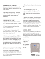
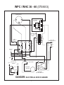
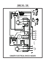
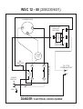
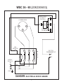
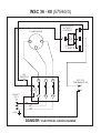
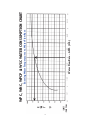
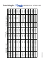
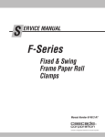
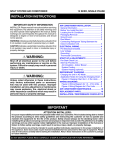
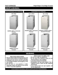
by
by
AITONS'
Water Cooled
Air Conditioners
AITONS'
by
by
AITONS'
AITONS'
WPC • WHC • WSC
Installation, Operation
And Maintenance Manual
WPC • WHC • WSC
ALL WIRING SHOULD COMPLY WITH LOCAL
AND NATIONAL CODES.
THE COMPRESSOR AND FAN MOTORS (If
applicable) ARE INTERNALLY PROTECTED.
INSTALLATION
by
AITONS'
WATER VALVE
The Water Regulating Valve is adjustable (by
means of stem on top of valve) to control
refrigerant system head pressure. Counter
clockwise rotation of the handle increases
head pressure and clockwise rotation
decreases the head pressure.
WHC Series
LOCATING THE UNIT
In locating the unit, consideration should be
given to space requirements, floor strength,
water supply, power supply, sewer for
condensate and condensate drain. In addition
to space required for the unit, consideration
should be given for service clearance and
maintenance.
It will be necessary to field adjust the valve
because of variance in water pressure, flow
rates and temperature encountered.
Fasten a service head pressure gauge to the
service fitting on the compressor discharge
line to determine the head pressure. The
optimum condition is 230 p.s.i.a.
WSC PRE-INSTALLATION
The water cooled system consists of a
condensing unit designed for installation with
refrigerant lines and matching evaporator coil.
Before beginning the installation, make certain
you have received the proper system
components for your requirements.
by
AITONS'
ELECTRICAL CONNECTIONS
All units are wired at the factory and require
connection of the power supply to the unit
control box. Power at the unit must be within
10% of rated voltage, both during normal
operation and starting periods.
WPC Series
2
OPERATION OF SYSTEM
6. Turn on the line voltage to the condensing
unit.
System is controlled by a room thermostat.
Place system switch on the thermostat to the
“cool” position.
7. Set the thermostat to 15°C. The
compressor contactor should close and the
compressor starts to work. The furnace
blower should start and run on the cooling
speed.
Place the fan switch to the “on” position for
continuous fan operation or the “auto” position
to cycle the blower on and off with the
compressor.
8. With the unit operating, close all the doors,
windows and openings to the house. Set the
thermostat to the desired setting, usually
22°C, allow the unit to condition the house.
Don’t be alarmed if the unit runs several hours
or even a full day to reduce the heat and
moisture in the house on the initial run. This
is normal for any air conditioning system.
CHECK OUT OF UNIT
1. Turn the thermostat Heat/Cool switch to
“off”. Turn the thermostat fan switch to “auto”.
2. Turn all power on except line voltage
(230v) to condensing unit.
SPECIAL NOTE
3. Turn fan switch at thermostat to “on”:
blower should run on cooling speed. Reset to
“auto”; blower should turn off.
In the event of a compressor motor failure or
burnout; normally cleaning the metering
device, installing a suction line filter drier will
be sufficient to remove contaminates resulting
from the failure.
4. Set the room thermostat above 30°C, turn
selector switch to cool. Move thermostat
below indicated room temperature; the blower
should run on a cooling speed and a click of
the compressor contactor should be heard in
the condensing unit. If the contactor cannot
be heard, check visually that the contacts are
closed.
After a few days
of operation,
the drier core
can be removed
from the suction
line filter.
5. Again, set room temperature above 30°C.
Turn selector switch to heat. Furnace should
start to heat. When plenum temperature
reaches fan on setting, the blower should run
at heating speed. turn thermostat down below
15°C, to shut off heat. After a few minutes the
blower should turn off.
by
AITONS'
WSC Series
3
GENERAL SERVICE GUIDE
PROBLEM
POSSIBLE
REMEDY
POSSIBLE
REMEDY
POSSIBLE
REMEDY
POSSIBLE
REMEDY
Fan and compressor will not start.
CAUSE
CAUSE
CAUSE
CAUSE
PROBLEM
POSSIBLE
REMEDY
POSSIBLE
REMEDY
POSSIBLE
REMEDY
POSSIBLE
REMEDY
Fan operates, but compressor will not start.
CAUSE
CAUSE
CAUSE
CAUSE
POSSIBLE CAUSE
REMEDY
PROBLEM
POSSIBLE
REMEDY
POSSIBLE
REMEDY
POSSIBLE
REMEDY
POSSIBLE
REMEDY
Incorrect thermostat setting.
Adjust thermostat.
Thermostat defective.
Replace.
Compressor overloads or thermostat open.
Check reasons for overload open: excessive heat.
High or low pressure control tripped.
Re-set and check water regulating valve and water supply.
If switch is defective, then replace.
Contactor faulty.
Replace.
Compressor motor hums but will not start.
CAUSE
CAUSE
CAUSE
CAUSE
PROBLEM
POSSIBLE
REMEDY
POSSIBLE
REMEDY
POSSIBLE
REMEDY
POSSIBLE
REMEDY
Power Off.
Check main circuit fuses and wiring.
(a) Faulty unit wiring (b) Loose wiring connections.
(a) Check wiring diagram (b) Tighten terminals and wiring connections.
24 volt supply faulty.
Check transformer.
Thermostat defective.
Replace.
Low or incorrect voltage.
Check with power company for required voltage.
Faulty capacitor.
Replace.
Faulty Hard Start Kit.
Replace.
Seized compressor.
Replace.
Fan motor starts but cuts off on internal protector.
CAUSE
CAUSE
CAUSE
CAUSE
Low voltage.
Check with power company.
Defective bearings.
Replace motor.
Internal fault.
Replace motor.
High amp draw.
Replace motor.
4
PROBLEM
POSSIBLE CAUSE
REMEDY
POSSIBLE CAUSE
REMEDY
POSSIBLE CAUSE
REMEDY
POSSIBLE CAUSE
REMEDY
PROBLEM
POSSIBLE CAUSE
REMEDY
POSSIBLE CAUSE
REMEDY
POSSIBLE CAUSE
REMEDY
High Suction Pressure.
Water supply inadequate.
Check water regulating valve setting or water supply.
Excessive load on unit.
High air flow, high inlet temperature as in initial start or pull down.
Defective compressor.
If head pressure is low or normal at this condition, compressor may be
defective.
Overcharge of refrigerant.
Usually associated with high discharge pressure. Remove excess gas.
High Discharge Pressure.
Water supply to condenser inadequate.
(a) Adjust or, if defective, replace water regulating valve.
(b) Water pressure low, or supply lines too small.
(c) Water temperature too high.
(d) Condenser surface fouled.
Recognized by low temperature water rise through condenser.
Overcharge of refrigerant.
Remove refrigerant, and balance to normal.
Non-condensibles in system.
Remove refrigerant and evacuate system.
5
WPC / WHC 12 - 60 (208/230/60/1)
COMPRESSOR
R
SOLID STATE
LOCKOUT
CONTROL
C
LOGIC
CIRCUIT
S
4
1
FAULT
LIGHT
3
2
CONTROL
208/230 - 24V
TRANS
COMP
CAP
HP
SWITCH
T2
COIL
SUPPLY
208/230 V
1O
L1
CONTACTOR
T1
24 V TO
THERMOSTAT
G
R
Y
L2
GND
OPTIONAL
MOTOR AND
FROM
WIRING
L1
CAPACITOR
4
2
FROM
MOTOR
RELAY
5
CAPACITOR
BLOWER
MOTOR
1
COIL
3
BLOWER
MOTOR
BLOWER
MOTOR RELAY
DANGER: ELECTRICAL SHOCK HAZARD
6
WPC / WHC 36 - 60 (208/230/60/3)
COMPRESSOR
T1
SOLID STATE
LOCKOUT
CONTROL
T3
LOGIC
CIRCUIT
T2
4
1
FAULT
LIGHT
3
2
CONTROL
208/230 - 24V
TRANS
HP
SWITCH
T2
T3
CONTACTOR
T1
COIL
SUPPLY
208/230 V
3O
L1
L2
24 V TO
THERMOSTAT
G
R
Y
L3
GND
OPTIONAL
MOTOR AND
FROM
WIRING
L1
CAPACITOR
4
2
FROM
MOTOR
RELAY
5
CAPACITOR
BLOWER
MOTOR
1
COIL
3
BLOWER
MOTOR
BLOWER
MOTOR RELAY
DANGER: ELECTRICAL SHOCK HAZARD
7
WPC / WHC 36 - 60 (575/60/3)
COMPRESSOR
T1
SOLID STATE
LOCKOUT
CONTROL
T3
LOGIC
CIRCUIT
T2
4
1
FAULT
LIGHT
3
2
CONTROL
575 - 24V
TRANS
HP
SWITCH
T2
T3
CONTACTOR
T1
COIL
SUPPLY
575 V
3O
L1
L2
24 V TO
THERMOSTAT
G
R
Y
L3
GND
OPTIONAL
MOTOR AND
FROM
WIRING
L1
CAPACITOR
4
2
FROM
MOTOR
RELAY
5
CAPACITOR
BLOWER
MOTOR
1
COIL
3
BLOWER
MOTOR
BLOWER
MOTOR RELAY
DANGER: ELECTRICAL SHOCK HAZARD
8
9
GND
L2
L3
T1
208-230/60/3
460/60/3
575/60/3
SUPPLY
T2
T2
T3
T3
COMPRESSOR
L1
T1
24 V TO
THERMOSTAT
COIL
FAULT
LIGHT
LOGIC
CIRCUIT
HP
SWITCH
2
3
1
R
L1
T1
G
Y1
L2
T2
BLOWER
MOTOR x2
Y2
COIL
C
HP
SWITCH
T2
L2
T2
T3
L3
FAULT
LIGHT
CONTROL
208-230 - 24V
TRANS
RED
YELLOW
T3
BLOWER
MOTOR
LOW SPEED
L1
BLACK
COIL
T1
T1
COMPRESSOR
2
SOLID STATE
LOCKOUT
CONTROL
CONTACTOR
4
CONTACTOR
LOGIC
CIRCUIT
SOLID STATE
LOCKOUT
CONTROL
3
1
4
RED
HIGH SPEED
BLOWER
MOTOR
YELLOW
BLACK
WHC 90 - 120
(208/230/60/3 460/60/3 575/60/3)
DANGER: ELECTRICAL SHOCK HAZARD
CONTACTOR
10
GND
L2
L3
T1
208-230/60/3
460/60/3
575/60/3
SUPPLY
T2
T2
T3
T3
COMPRESSOR
L1
T1
24 V TO
THERMOSTAT
COIL
FAULT
LIGHT
LOGIC
CIRCUIT
HP
SWITCH
2
R
3
1
L1
T1
G
Y1
L2
T2
BLOWER
MOTOR x2
COIL
Y2
C
HP
SWITCH
T2
L2
T2
T3
L3
FAULT
LIGHT
CONTROL
208-230 - 24V
TRANS
RED
YELLOW
T3
BLOWER
MOTOR
LOW SPEED
L1
BLACK
COIL
T1
T1
COMPRESSOR
2
SOLID STATE
LOCKOUT
CONTROL
CONTACTOR
4
LOGIC
CIRCUIT
SOLID STATE
LOCKOUT
CONTROL
3
1
4
RED
HIGH SPEED
BLOWER
MOTOR
YELLOW
BLACK
WPC 90 - 120
(208/230/60/3 460/60/3 575/60/3)
DANGER: ELECTRICAL SHOCK HAZARD
CONTACTOR
WSC 12 - 60 (208/230/60/1)
COMPRESSOR
SOLID STATE
LOCKOUT
CONTROL
C
S
2
4
LOGIC
CIRCUIT
R
1
FAULT
LIGHT
3
COMP
CAP
T1
T2
COIL
SUPPLY
208/230 V
1O
L1
CONTACTOR
HP
SWITCH
24 V TO
THERMOSTAT
C
L2
GND
DANGER: ELECTRICAL SHOCK HAZARD
11
Y
WSC 36 - 60 (208/230/60/3)
COMPRESSOR
2
T1
T3
T2
4
LOGIC
CIRCUIT
SOLID STATE
LOCKOUT
CONTROL
1
FAULT
LIGHT
3
T1
T2
T3
COIL
SUPPLY
208/230 V
3O
L1
L2
CONTACTOR
HP
SWITCH
24 V TO
THERMOSTAT
C
L3
GND
DANGER: ELECTRICAL SHOCK HAZARD
12
Y
WSC 36 - 60 (575/60/3)
COMPRESSOR
2
T1
T3
T2
4
LOGIC
CIRCUIT
SOLID STATE
LOCKOUT
CONTROL
1
FAULT
LIGHT
3
T1
T2
T3
COIL
SUPPLY
575 V
3O
L1
L2
CONTACTOR
HP
SWITCH
24 V TO
THERMOSTAT
C
L3
GND
DANGER: ELECTRICAL SHOCK HAZARD
13
Y
14
Water Flow Rate – G.P.M. (U.S.)
Entering Water Temperatures vs. Water Flow Rate
WPC, WHC, WPCP & WSC WATER CONSUMPTION CHART
15
FB0003
FM0002
FM0010/FM0004
FM0011/FM0005
WPC/WHC120
WPC/WHC120-5
REVISED 5/02
FM0009/FM0005
FB0004
FM0005
WPC/WHC90-5
FB0004
FM0004
FB0006/FB0004
FB0006/FB0004
FB0005/FB0004
FB0005/FB0004
FB0004
FM0004
FM0008/FM0004
FB0004
FB0003
FM0004
FM0002
FB0003
FB0003
FM0002
FM0002
FB0002
FM0001
WPC/WHC90-3
WPC/WHC48
WSC *
WPC/WHC60-1
WSC *
WPC/WHC60-3
WSC *
WPC/WHC60-5
WSC *
WPC/WHC44-3
WPC/WHC44-1
FB0002
FM0001
FB0002
FB0002
FM0001
WPC/WHC15
FB0002
BLOWER WHEEL
FM0001
FM0001
WPC/WHC12
WPC/WHC18
WSC *
WPC/WHC24
WSC *
WPC/WHC30
WSC *
WPC/WHC36-1
WSC *
WPC/WHC36-3
WSC *
MOTOR
MODEL
PARTS LISTING FOR
RC0021 (2)
RC0013 (2)
RC0020 (2)
RC0012 (2)
RC0021
RC0013
RC0009
RC0008
RC0011
RC0007
RC0010
RC0006
RC0005
RC0004
RC0002
8000-632
RC0001
COMPRESSOR
by
EO0002
EO0002
EO0002
EO0002
EO0002
EO0002
EO0000
EO0001
EO0002
EO0001
EO0002
EO0001
EO0001
EO0001
EO0001
EO0001
EO0001
CONTACTOR
COMFORT-AIRE
AITONS'
EC0015
EC0015
EC0015
EC0015
EC0015
EC0001
EC0001
EC0001
EC0001
EC0001
EC0001
EC0001
EC0001
EC0001
EC0011
EC0010
EC0010
EC0010
EC0007
EC0007
EC0007
EC0007
EC0005
MOTOR CAPACITOR COMP
WPC/WHC/WSC 12 THRU 120-5
REVISED 08/14/01
VW0002
VW0002
VW0002
VW0002
VW0002
VW0002
VW0002
VW0002
VW0001
VW0001
VW0001
VW0001
VW0001
VW0001
VW0001
VW0001
VW0001
WATER VALVE
Parts Listing for
WPC/WHC/WSC 12 THRU 120-5
www.comfort-aire.com
LIMITED WARRANTY
Water Cooled Equipment
AITONS’ EQUIPMENT INC. warrants for one year its products to be free from
defects in material and workmanship when installed and operated pursuant to
manufacturers instructions.
In addition, the compressor is warranted for an additional 4 years.
If, upon examination by AITONS’ EQUIPMENT INC., a part is deemed to be
defective under this warranty, we will repair or replace that part F.O.B.
Guelph, Ontario free of charge, exclusive of labour.
This warranty is to the exclusion of any statutory warranty expressed or
implied.
The PURCHASER FILLS IN AND RETAINS THIS WARRANTY (The Serial
Number of your unit is recorded on computer when shipped.)
MODEL
SERIAL number
DATE OF INSTALLATION
INSTALLER’S NAME
AITONS’ EQUIPMENT INC.
Guelph, Ontario
www.aitons.com
[email protected]
16