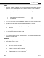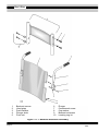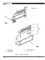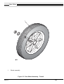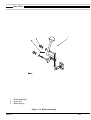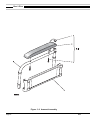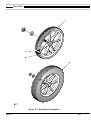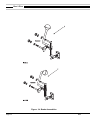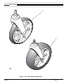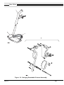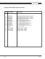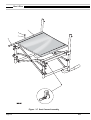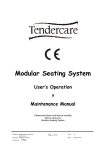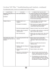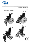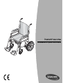
1
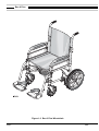
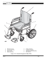
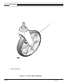
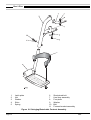
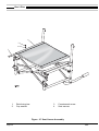
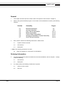
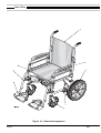
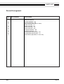
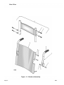
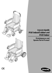
Invacare
R
Ben 9 Plus
Maintenance & Spare Parts Manual
Ben 9 Plus
Contents
Chapter 1
Page
Introduction
Introduction . . . . . . . . . . . . . . . . . . . . . . . . . . . . . . . . . . . . . . . . . . . . . . . . . . . .1.3
Policy . . . . . . . . . . . . . . . . . . . . . . . . . . . . . . . . . . . . . . . . . . . . . . . . . . . . . . . .1.5
Technical Details . . . . . . . . . . . . . . . . . . . . . . . . . . . . . . . . . . . . . . . . . . . . . . . .1.5
Types . . . . . . . . . . . . . . . . . . . . . . . . . . . . . . . . . . . . . . . . . . . . . . . . . . . . . . . .1.5
Chapter 2
Maintenance
Scope . . . . . . . . . . . . . . . . . . . . . . . . . . . . . . . . . . . . . . . . . . . . . . . . . . . . . . . .2.3
Inspection . . . . . . . . . . . . . . . . . . . . . . . . . . . . . . . . . . . . . . . . . . . . . . . . . . . . .2.3
Tools . . . . . . . . . . . . . . . . . . . . . . . . . . . . . . . . . . . . . . . . . . . . . . . . . . . . . . . . .2.4
Removing And Replacing Backrest Canvas . . . . . . . . . . . . . . . . . . . . . . . . . . . .2.7
Removing And Replacing An Armrest Assembly . . . . . . . . . . . . . . . . . . . . . . . . .2.9
Removing And Replacing Main Wheel Assemblies . . . . . . . . . . . . . . . . . . . . . .2.11
Removing And Replacing A Brake Assembly . . . . . . . . . . . . . . . . . . . . . . . . . .2.13
Removing And Replacing A Castor Wheel Assembly . . . . . . . . . . . . . . . . . . . .2.15
Removing And Replacing An Adjustable Footrest Assembly . . . . . . . . . . . . . . .2.17
Removing And Replacing Seat Canvas . . . . . . . . . . . . . . . . . . . . . . . . . . . . . .2.19
Chapter 3
Illustrated Parts List
Backrest Assembly . . . . . . . . . . . . . . . . . . . . . . . . . . . . . . . . . . . . . . . . . . . . . . .3.7
Armrest Assembly . . . . . . . . . . . . . . . . . . . . . . . . . . . . . . . . . . . . . . . . . . . . . . .3.9
Rear Wheel Assemblies . . . . . . . . . . . . . . . . . . . . . . . . . . . . . . . . . . . . . . . . . .3.11
Brake Assemblies . . . . . . . . . . . . . . . . . . . . . . . . . . . . . . . . . . . . . . . . . . . . . .3.13
Castor Wheel Assemblies . . . . . . . . . . . . . . . . . . . . . . . . . . . . . . . . . . . . . . . .3.15
Swinging Detachable Footrest Assembly . . . . . . . . . . . . . . . . . . . . . . . . . . . . .3.17
Seat Canvas Assembly . . . . . . . . . . . . . . . . . . . . . . . . . . . . . . . . . . . . . . . . . .3.19
Page 2
04/02
INTRODUCTION
Chapter 1
Introduction
04/02
Page 3
Ben 9 Plus
Figure 1.0 Ben 9 Plus Wheelchair
Page 4
04/02
INTRODUCTION
Introduction
1
This manual provides basic details to enable the BEN 9 Plus range of wheelchairs to be maintained. It is
not intended to be a comprehensive maintenance guide/policy, but is intended for use by competent
personnel to enable the chair to be adequately maintained.
2
The manual is split into the following chapters:
3
Chapter 2
Detailing assemblies that are maintainable and the relevant procedures.
Chapter 3
Detailing parts that are available to enable the maintenance in Chapter 2 to be complied
with.
The BEN 9 range of wheelchair is manufactured by:
INVACARE Ltd
South Road
Bridgend Industrial Estate
Bridgend
Mid-Glamorgan
CF31 3PY
4
For Customer Service enquires, repairs, servicing and spares, contact INVACARE Ltd at the address
below and quote all the details as indicated in paragraphs 6 and 7.
5
INVACARE Ltd
South Road
Bridgend Industrial Estate
Bridgend
Mid-Glamorgan
CF31 3PY
Tel No:
Fax No:
6
7
04/02
01656 647327
01656 649016
Quote the following details at all times:
6.1
Part Number
6.2
Description
6.3
Quantity required
For certain orders the following should also be quoted:
7.1
Serial or batch number
7.2
End user
Page 5
Ben 9 Plus
Figure 1.0 Ben 9 Plus Wheelchair
Page 6
04/02
INTRODUCTION
Policy
8
INVACARE Ltd. repair policy is as follows:
Repairs to ANY component other than those detailed in Chapter 2 are not covered. Repairs to ANY metal
work is not generally permitted without express permission of INVACARE Ltd. ALL fasteners i.e. bolts,
Nyloc nuts, and any fastener showing damage MUST be renewed.
Failure to comply with the above absolves INVACARE Ltd of liability.
! Note:
Certain components will require removal to carry out maintenance. With the exception of fasteners, these components should be refitted.
Technical Details
9
The following data applies to the Ben 9 range of wheelchairs.
9.1
Available seat sizes:
15 inches by 16 inches, 17 inches by 17 inches and 18 inches by 17 inches and 16 inches by
16 inches.
9.2
Seat to ground height:
19 inches.
9.3
Wheel types available:
12 1/2 inches transit with pneumatic or solid tyre. Located to frame.
9.4
Maximum user weight:
20 stones (127kgs)
9.5
Backrest type:
Folding backrest.
9.6
Chair finish:
Powder coat in red or black.
9.7
Transit weight of chair:
29lbs (13.2kgs).
Types
Options
10
04/02
The chair is available in various user defined optional types. For further details refer to INVACARE Ltd for
details and acceptable combinations.
Page 7
Ben 9 Plus
LEFT BLANK INTENTIONALLY
Page 8
04/02
MAINTENANCE
Chapter 2
Maintenance
04/02
Page 2.1
Ben 9 Plus
1
2
3
4
Backrest canvas
Armrest assembly
Rear wheels
Brake assembly
5
6
7
8
Castor assembly
Footplate assembly
Swinging bracket assembly
Seat canvas
Figure 2.0.1 General Arrangement of Ben 9 Plus
Page 2.2
04/02
MAINTENANCE
Scope
1
This chapter details the removal and/or replacement procedures required for the following assemblies
and/or items. It is not intended to be a strict policy of maintenance but should be used as a guide only.
2
The assemblies covered (refer to Fig 2.0.1) are as follows:
Section
Assembly
Page
2.1
Backrest
2.6
2.2
Armrest
2.8
2.3
Rear wheels (12 1/2 inches)
2.10
2.4
Brake assembly
2.14
2.5
Removing and replacing a castor assembly
2.16
2.6
Adjustable footrest
2.18
2.7
Seat canvas
2.20
3
For the tools required refer to the list of tools detailed in paragraph 12. Any special tooling and/or torque
requirements will be referred to within the relevant text.
4
General engineering practices and safe working practices must be adhered to at all times.
5
For further information on the assemblies contained within this chapter, contact Customer Services,
INVACARE Ltd., (refer to address in chapter 1) quoting the following details:
6
7
5.1
Part Number
5.2
Description
5.3
Quantity required
For certain orders the following should also be quoted:
6.1
Serial or batch number
6.2
End user
For any ordering or spares procurement, contact INVACARE Ltd., (refer to address in Chapter 1) quoting
the details in paragraphs 5 and 6.
Inspection
8
In general, a weekly visual check will meet all the inspection requirements.
9
Ensure that the following are checked:
04/02
9.1
Fabric is undamaged and has no signs of sagging.
9.2
The footrest is correctly fitted.
9.3
Both armrests are securely fitted in place.
9.4
Brake mechanism operates freely and when locked, the chair does not move.
9.5
Footplates are undamaged and are correctly fitted.
9.6
Tyres are in good order and the wheels are not damaged.
9.7
If stabilisers are fitted, they are firmly locked in place.
Page 2.3
Ben 9 Plus
1
2
3
4
Backrest canvas
Armrest assembly
Rear wheels
Brake assembly
5
6
7
8
Castor assembly
Footplate assembly
Swinging bracket assembly
Seat canvas
Figure 2.0.1 General Arrangement of Ben 9 Plus
Page 2.4
04/02
MAINTENANCE
10
Check the finish of the chair for any damage.
! Note:
Some finishes are unique to the chair. Check with INVACARE Ltd for details.
11
Check that all bungs and handgrips are fitted and undamaged.
12
Before reassembly of any components, the following examination should be carried out:
12.1
All brazed joints should be examined and any damaged component should be replaced.
12.2
All plated parts should be checked to ensure that surfaces are free from wear, damage or oxidation.
12.3
All Nyloc nuts should be replaced after removal.
Tools
13
The following list details the basic tools required to carry out the maintenance given in the following subchapters.
13.1
Pliers
13.2
Socket set (Metric and Imperial)
13.3
Spanners (Metric and Imperial)
13.4
Pozidriv screwdriver
13.5
Slotted screwdriver
13.6
Adjustable spanner
13.7
Torque wrench (20 to 40 lbf.ft rating)
13.8
Set of Allen keys (Metric and Imperial)
13.9
Protected jaw grips
13.10 Nylon mallet
13.11 Pop rivet gun
13.12 Nut insert application tool
13.13 Rule
! Note:
04/02
The above list is not exhaustive.
Page 2.5
Ben 9 Plus
1
2
3
4
Backrest canvas
Hand grips
Push handles
Plunger knob
5
6
7
8
Pivot bolt
Plunger
Countersunk screw
Cup washer
Figure 2.1 Folding Backrest Assembly
Page 2.6
04/02
MAINTENANCE
2.1 Removing And Replacing The Backrest Canvas
General
1
Check the backrest canvas (1) and push handles (3) for any defects, (refer to paragraphs 4 and 5). If any
defects are observed then refer to paragraphs 6 to 7 for maintenance details and to Chapter 3 for parts
information.
2
Ensure that the push handle locks securely into place and that the locking mechanism functions correctly.
Tools
3
Refer to the tool list at the beginning of this Chapter.
Inspection
4
5
Inspect on a weekly basis for the following:
4.1
No signs of sagging, stretching or excessive wear in the canvas (1).
4.2
No evidence of fraying, especially around the fastener points.
4.3
Pozidriv head screws (5) not missing..
4.4
Cup washers not missing.
Inspect the locking mechanism for the following:
5.1
Release levers are not deformed or damaged.
5.2
Locks safely when the push handle (3) is in the upright position.
5.3
Not excessively stiff to operate (action should be smooth and positive).
Removal of the backrest canvas
6
To remove or replace the backrest canvas (1) proceed as follows:
6.1
Unscrew and remove the six pozidriv head countersunk screws (7) and cup washers (8).
6.2
Unscrew and remove the two button head pivot bolts (5), Nyloc nuts and washers.
6.3
Hold the push handle (3), and slide the lower half of the backrest canvas (1) off.
6.4
Remove plunger (4) and plunger knob (6).
6.5
Hold the backrest canvas and slide the push handle out.
Replacing the backrest canvas
7
04/02
To replace the backrest canvas is the reverse of the removal, however ensure the following:
7.1
New Nyloc nuts are fitted.
7.2
The securing points are undamaged.
7.3
New washers are fitted as required.
7.4
That the backrest canvas is stretched evenly and is taut.
Page 2.7
Ben 9 Plus
1
2
3
4
5
Backrest canvas
Hand grips
Push handles
Plunger knob
Pivot bolt
6
7
8
9
10
Plunger
Countersunk screw
Cup washer
Backrest extension
Locating ring kit
Figure 2.1.1 Backrest Extension Assembly
Page 2.8
04/02
MAINTENANCE
2.1.1
Removing And Replacing A Backrest Extension
General
1
Check backrest extension for any defects (refer to paragraph 3). If any defects are observed then refer to
paragraphs 4 to 6 for maintenance details and to Spares Catalogue for parts information.
Tools
2
Refer to the tool list at the beginning of this Chapter.
Inspection
3
Check for the following:
3.1
Damage to backrest extension canvas.
3.2
Screws (7), washer (8) and locating ring (10) missing and/or damaged.
3.3
Backrest extension is correctly fitted.
Removing Backrest Extension
4
To remove backrest extension proceed as follows:
4.1
Lift the backrest extension upwards and then sidewards off the locating rings (10).
Replacing The Backrest Extension
5
Replacing the backrest extension is the reverse of the removal.
Fitting a Backrest Extension for the first time
6
04/02
Fitting a Backrest Extension for the first time, proceed as follows:
6.1
Remove taptite screw (7) and washer (8) from top of push handle.
6.2
Fit four locating rings (10) with taptite screws (7) to side of push handles (3).
6.3
Slide the backrest extension firmly onto the locating rings (10).
Page 2.9
Ben 9 Plus
Figure 2.2 (a)
1
2
3
Sealing plug
Armrest pad
Armrest frame
4
5
Pozidriv head screw
Armrest panel
Figure 2.2 Armrest Assembly
Page 2.10
04/02
MAINTENANCE
2.2 Removing And Replacing An Armrest Assembly
General
! Note: The armrest assembly comprises the following:
The armrest pad (2), panel (5) and frame (3).
1
Check the armrest pad (2) and frame (3) for any defects (refer to paragraph 4). If any defects are observed
then refer to paragraphs 5 to 7 for maintenance details and to Chapter 3 for parts information.
2
The armrest can be renewed as either:
2.1
A complete assembly.
2.2
Armpad kit (KIT 1).
Tools
3
Refer to the tool list at the beginning of this Chapter.
Inspection
4
Inspect on a weekly basis for the following:
4.1
Frame (3), panel (5) and finish are undamaged.
4.2
Armrest pad (2) is undamaged and securely fastened in place.
Repairing An Armrest Assembly
! Note: For ease of maintenance the armrest assembly can be replaced as a complete assembly. For removal
refer to Figure 2.2 (a).
5
To repair the armrest assembly remove it from the wheelchair by turning the release lever and proceed as
follows:
5.1
6
7
Support the frame (3) using a soft jawed vice.
Removing the armrest pad (2).
6.1
Unscrew and remove the two pozidriv screws (4).
6.2
Remove the armrest pad from the frame.
Removing a panel (5).
7.1
The armrest panel (5) of the armrest is a snap fit onto the armrest frame and can be removed by
holding the armrest frame (3) firmly whilst pushing the panel forwards.
Replacing Armrest Components
8
04/02
To replace any of the components of the armrest is the reverse of the removal; however ensure the
following:
8.1
The panel (5) is flush fitting to the frame (3).
8.2
Sealing plug (1) are undamaged when replaced.
Page 2.11
Ben 9 Plus
1
Wheel assembly
Figure 2.3 Rear Wheel Assembly - Transit
Page 2.12
04/02
MAINTENANCE
2.3 Removing And Replacing Rear Wheel Assemblies
General
1
The Ben 9 range of wheelchairs can be fitted with the following wheel types:
(a)
12 1/2 inch solid Transit style
(b)
12 1/2 inch pneumatic Transit style
2
Check the wheel assembly for any defects (refer to paragraph 5). If any defects are observed then refer
to paragraphs 6 to 11 for maintenance details and to Chapter 3 for parts.
3
The rear wheel assembly can be renewed as either:
3.1
A complete assembly.
3.2
Replacement tyre and inner tube (if pneumatic).
Tools
4
Refer to the tool list at the beginning of this Chapter.
4.1
A torque wrench of 25 lbf.ft rating is required.
Inspection
5
Inspect on a weekly basis for the following:
5.1
Damage to either wheel or tyre.
5.2
When the wheel assembly is allowed to free wheel that no binding, grating noise or unconcentric
rotation are present.
5.3
Wheel rim and spokes are undamaged.
Removing A Transit Wheel Assembly
6
04/02
To remove a transit wheel (1) (refer to Fig 2.3) proceed as follows:
6.1
Raise and support the chair so the damaged wheel is free of the ground.
6.2
Using a suitable size spanner grip the nut located behind the wheel hub.
6.3
Using the torque wrench, unscrew and remove the locknut.
6.4
Slide the wheel free from its location on the frame.
Page 2.13
Ben 9 Plus
1
1
2
3
Brake assembly
Nyloc Nut
Brake Spring
Figure 2.4 Brake Assembly
Page 2.14
04/02
MAINTENANCE
2.4 Removing And Replacing A Brake Assembly
General
!Note: The brake assembly is handed, ensure that if both assemblies are removed that the correct assembly
is fitted to the correct side.
1
Check the brake assembly for any defects (refer to paragraph 4). If any defects are observed then refer
to paragraphs 5 to 6 for maintenance details and to Chapter 3 for parts information.
2
It is not intended that any other part is maintainable.
Tools
3
Refer to the tool list at the beginning of this Chapter.
Inspection
4
Check the following daily:
4.1
Brake assembly fully locks and the chair is unable to move.
4.2
Brake action is positive and is not stiff.
Removing A Brake assembly
! Note: (a)
5
For ease of maintenance the brake assembly can be removed as a complete assembly.
(b)
Note the position of the brake assembly.
(b)
The following procedure applies to any brake assembly.
To remove the brake assembly proceed as follows:
5.1
Ensure that brake assembly is in the unlocked position.
5.2
Support the brake assembly and unscrew the nyloc nuts (2) fastening the brake assembly to the
chair frame.
5.3
Unclip and remove the brake spring (3).
5.4
Remove the brake assembly (1) from its location.
Replacing A Brake Assembly
6
04/02
To replace a brake assembly is the reverse of the removal.
Page 2.15
Ben 9 Plus
1
Castor assembly
Figure 2.5 Castor Wheel Assembly
Page 2.16
04/02
MAINTENANCE
2.5 Removing And Replacing A Castor Wheel Assembly
General
1
Check the castor wheel assembly for any defects (refer to paragraph 4). If any defects are observed then
refer to paragraphs 5 to 8 for maintenance details and to Chapter 3 for parts information.
2
It is not intended that any other part is maintainable.
Tools
3
Refer to the tool list at the beginning of this Chapter.
Inspection
4
Check the following:
4.1
Castor fork is undamaged.
4.2
Tyre is not cracked or excessively worn.
4.3
Castor wheel rotates freely when lifted clear of the ground and spun.
4.4
The tyre is firmly fitted and concentric within the rim.
Removing A Castor Wheel Assembly
5
To remove the castor wheel assembly proceed as follows:
5.1
Raise and support the front of the chair.
5.2
Using a torque wrench unscrew the castor wheel until the castor assembly releases from its
location.
5.3
Remove the castor wheel assembly.
5.4
Check that the castor wheel location is undamaged and clean.
Replacing A Castor Wheel Assembly
CAUTION: Apply Loctite 242 to the thread of the castor wheel shaft and ensure that the
castor wheel is tightened using the fork nut to a torque of 30 lbf.ft.
6
7
04/02
Replacing the castor wheel assembly is the reverse of the removal; ensure the following:
6.1
It is firmly located and secure.
6.2
Freely to rotate through 360 degrees.
6.3
Is undamaged.
Once correctly fitted, remove the support and allow the chair to sit on all four wheels. Check that it
functions correctly.
Page 2.17
Ben 9 Plus
1
2
3
4
5
Latch plate
Nut
Washer
Shim
Spring
6
7
8
9
10
11
Shouldered bolt
Heel loop assembly
Foot plate
Washer
Bolt
Footrest bracket assembly
Figure 2.6 Swinging/Detachable Footrest Assembly
Page 2.18
04/02
MAINTENANCE
2.6 Removing And Replacing An Adjustable Footrest Assembly
General
1
Check the adjustable footrest assembly for any defects (refer to paragraph 3). If any defects are observed
then refer to paragraphs 5 to 9 for maintenance details and to Chapter 3 for parts information.
Tools
2
Refer to the tool list at the beginning of this Chapter.
Inspection
3
4
Check the following:
3.1
Footplate (Fig 2.6 (8)) is undamaged, fitted securely to the Stem Tube assembly, swivels up and
down smoothly and is effectively supported in horizontal.
3.2
Heel Sling assembly (7) is undamaged and securely fastened to the Footplate (8).
3.3
Latching mechanism (1) functions correctly and the footrest assembly locks securely in place.
3.4
Stem Tube assembly is undamaged.
3.5
Locating holes and Lugs are free from damage.
Any defects to the above will require the assembly to be repaired.
Removing A Swing/Detachable Footrest Assembly
5
To remove the swing/detachable footrest assembly proceed as follows:
5.1
Operate the latching mechanism and allow the footrest assembly to rotate away from the frame.
5.2
Lift the swing/detachable footrest assembly free of the locating lugs.
Replacing A Swing/Detachable Footrest Assembly
6
04/02
Replacing any component previously mentioned is the reverse of the removal.
Page 2.19
Ben 9 Plus
1
2
Reinforcing bar
Cup washer
3
4
Countersunk screw
Seat canvas
Figure 2.7 Seat Canvas Assembly
Page 2.20
04/02
MAINTENANCE
2.7 Removing And Replacing Seat Canvas
General
1
Check the seat canvas (4) for any defects (refer to paragraph 3). If any defects are observed then refer to
paragraphs 5 to 6 for maintenance details and to Chapter 3 for parts information.
Tools
2
Refer to the tool list at the beginning of this Chapter.
Inspection
3
4
Check for the following:
3.1
Damage to seat canvas (4).
3.2
Sagging.
3.3
Reinforcing bar missing and/or damaged.
Generally replace and/or tighten any screws (3) or cup washers (2) that are missing/damaged.
Removing The Seat Canvas
5
To remove the seat canvas (4) proceed as follows:
5.1
Unscrew and remove the countersunk head screws (3) and cup washers (2).
Replacing The Seat Canvas
! Note: Check the order for the correct seat canvas size.
6
04/02
Replacing the seat canvas is the reverse of the removal, refer to Chapter 3 for parts information.
Page 2.21
Ben 9 Plus
LEFT BLANK INTENTIONALLY
Page 2.22
04/02
PARTS LIST
Chapter 3
Illustrated Parts List
04/02
Page 3.1
Ben 9 Plus
LEFT BLANK INTENTIONALLY
Page 3.2
04/02
PARTS LIST
General
1
This chapter has been split into sections which correspond to the sections in Chapter 2.
2
Refer to the general assembly Figure 3.0 for location of the assemblies covered by the following
sections:
Section
3.1
3.2
3.3
3.4
3.5
3.6
3.7
3
Assembly
Backrest Assembly
Armrest Assembly
Rear Wheel Assemblies
Brake Assemblies
Castor Wheel Assemblies
Swinging Detachable Footrest Assembly
Seat Canvas Assembly
Pages
6-7
8-9
10-11
12-13
14-15
16-17
18-19
Each section contains the following information in table format:
3.1
Fig/Item reference number
3.2
Part Number
3.3
Description
! Note: The following references are used:
NI
When an assembly or component is not illustrated.
Ordering Information
4
5
04/02
To order components or parts information from the relevant address, refer to Chapter 1. Always
quote the following:
4.1
Part Number
4.2
Description
For certain orders the following should also be quoted
5.1
Serial or batch number
5.2
End user
Page 3.3
Ben 9 Plus
Figure 3.0 General Arrangement
Page 3.4
04/02
PARTS LIST
General Arrangement
Item
1
2
NI
3
4
NI
5
NI
6
NI
7
NI
8
04/02
Part Number
Description
Backrest Assembly
Armrest Assembly - LH
Armrest Assembly - RH
Main Wheels (Dependant on order)
Brake Assembly - LH
Brake Assembly - RH
Castor Assembly - LH
Castor Assembly - RH
Footplate Assembly - RH
Footplate Assembly - LH
Swinging Bracket Assembly - RH
Swinging Bracket Assembly - LH
Seat Canvas (Dependant on chair size)
Page 3.5
Ben 9 Plus
Figure 3.1 Backrest Assembly
Page 3.6
04/02
PARTS LIST
Backrest Assembly
Item
NI
NI
1
NI
NI
NI
NI
NI
4
NI
NI
NI
9
NI
NI
NI
04/02
Part Number
Description
SKA2290KIT
SKA2347KIT
9000/41KIT
SKA2324KIT
SKA2290PKIT
SKA2347PKIT
SKA1331PKIT
SKA1734PKIT
9000/18BLKKIT
9000/18REDKIT
9000/16BLKKIT
9000/16 REDKIT
9503/50B/EVA
9514/50B/EVA
9003/50B/EVA
9018/50B/EVA
15" W/R Back Canvas Assembly - incl. items 2 and 3
16" W/R Back Canvas Assembly - incl. items 2 and 3
17" W/R Back Canvas Assembly - incl. items 2 and 3
18" W/R Back Canvas Assembly - incl. items 2 and 3
15" W/R Padded Back Canvas Assembly - incl. items 2 and 3
16" W/R Padded Back Canvas Assembly - incl. items 2 and 3
17" W/R Padded Back Canvas Assembly - incl. items 2 and 3
18" W/R Padded Back Canvas Assembly - incl. items 2 and 3
Push Handle Kit, Black - LH - incl. items 5 to 8
Push Handle Kit, Red - LH - incl. items 5 to 8
Push Handle Kit, Black - RH - incl. items 5 to 8
Push Handle Kit, Red - RH - incl. items 5 to 8
15” W x 9” High Backrest Extension Assembly
16” W x 9” High Backrest Extension Assembly
17” W x 9” High Backrest Extension Assembly
18” W x 9” High Backrest Extension Assembly
Page 3.7
Ben 9 Plus
Figure 3.2 Armrest Assembly
Page 3.8
04/02
PARTS LIST
Armrest Assembly
Item
Part Number
Description
NI
NI
NI
NI
NI
NI
NI
NI
9003/10B/B
9003/10R/B
9503/10B/B
9503/10R/B
9003/12B/B
9503/12B/B
9003/12R/B
9503/12R/B
Armrest Assembly
Armrest Assembly
Armrest Assembly
Armrest Assembly
Armrest Assembly
Armrest Assembly
Armrest Assembly
Armrest Assembly
NI
NI
12" BLKPADKIT
10" BLKPADKIT
12" Black Armpad Kit (9L) incl. items 1 to 3
10" Black Armpad Kit (9LJ) incl. items 1 to 3
4
NI
9003/10/02BLK
SKA2153BLK
Armrest panel Black (9L)
Armrest panel Black (9LJ)
04/02
-
RH BLK/BLK (9L) incl. items 1 to 5
RH RED/BLK (9L) incl. items 1 to 5
RH BLK/BLK (9LJ) incl. items 1 to 5
RH RED/BLK (9LJ) incl. items 1 to 5
LH BLK/BLK (9L) incl. items 1 to 5
LH BLK/BLK (9LJ) incl. items 1 to 5
LH RED/BLK (9L) incl. items 1 to 5
LH RED/BLK (9LJ) incl. items 1 to 5
Page 3.9
Ben 9 Plus
Figure 3.3 Rear Wheel Assemblies
Page 3.10
04/02
PARTS LIST
Rear Wheel Assemblies
Item
1
2
3
4
NI
04/02
Part Number
Description
1315/02PNUBLK
M11005
M12004
1315/02WPBLK
M19003
315mm Wheel + Pneumatic Tyre
Inner Tube
Tyre
315mmSolid Black Wheel Assembly
Pump 15”
Page 3.11
Ben 9 Plus
Figure 3.4 Brake Assemblies
Page 3.12
04/02
PARTS LIST
Brake Assemblies
Item
Part Number
Description
1
NI
NI
NI
TSD4930BLK
TSD4930RED
TSD4929BLK
TSD4929RED
Brake Assembly
Brake Assembly
Brake Assembly
Brake Assembly
2
NI
NI
NI
9000/20BLKEXT
9000/20REDEXT
9000/25BLKEXT
9000/25REDEXT
Extended
Extended
Extended
Extended
04/02
-
LH Black
LH Red
RH Black
LH Red
Brake Assembly
Brake Assembly
Brake Assembly
Brake Assembly
-
RH Black
RH Red
LH Black
LH Red
Page 3.13
Ben 9 Plus
Figure 3.5 castor Wheel Assemblies
Page 3.14
04/02
PARTS LIST
Castor Wheel Assemblies
Item
Part Number
Description
1
2
1190/00BLK
1190/00WPBLK
190mm Narrow Profile Castor
190mm Wide Profile Castor
04/02
Page 3.15
Ben 9 Plus
Figure 3.6 Swinging Detachable Footrest Assembly
Page 3.16
04/02
PARTS LIST
Swinging Detachable Footrest Assembly
Item
Part Number
Description
1
NI
NI
NI
2
NI
NI
NI
NI
NI
NI
NI
3
9000/27BLK
9000/27RED
9000/33BLK
9000/33RED
9000/42BR
9000/42PLBLK
9000/46BR
9000/46PLBLK
8100/23BR
8100/23PLBLK
8100/25BR
8100/25PLBLK
8300/21
Swinging Bracket Assembly, Black - RH (9L/9LJ)
Swinging Bracket Assembly, Red- RH (9L/9LJ)
Swinging Bracket Assembly, Black - LH (9L/9LJ)
Swinging Bracket Assembly, Red - LH (9L/9LJ)
8.5" Footplate Assembly - RH (9L)
8.5" Plastic Footplate Assembly - RH (9L)
8.5" Footplate Assembly - LH (9L)
8.5" Plastic Footplate Assembly - LH (9L)
7.5" Footplate Assembly - RH (9LJ)
7.5" Plastic Footplate Assembly - RH (9LJ)
7.5" Footplate Assembly - LH (9LJ)
7.5" Plastic Footplate Assembly - LH (9LJ)
Heel Loop Assembly
4
NI
NI
NI
TSD11087BLK
TSD11087RED
TSD11350BLK
TSD11350RED
Elevating
Elevating
Elevating
Elevating
04/02
Legrest
Legrest
Legrest
Legrest
-
RH
RH
RH
RH
Black
Red
Black
Red
Page 3.17
Ben 9 Plus
Figure 3.7 Seat Canvas Assembly
Page 3.18
04/02
PARTS LIST
Seat canvas Assembly
Item
Part Number
Description
1
NI
NI
NI
NI
NI
NI
9000/38EVA
9000/38PEVA
9018/38EVA
9018/38PEVA
9500/10EVA
9500/11PEVA
TSD8072KIT
17x17
17x17
18x17
18x17
15x16
15x16
16x16
NI
5
TSD8072PKIT
ARMLOCKKIT
16x16 Seat Canvas Assembly Padded (9LJ) incl. items 2 to 4
Armrest Lock Kit Assembly
NI
NI
NI
NI
CUSH215x16EVA
CUSH216x16EVA
CUSH217x17EVA
CUSH218x17EVA
15”
16”
17”
17”
NI
6003196
Wheelchair Lap Strap
04/02
x
x
x
x
Seat
Seat
Seat
Seat
Seat
Seat
Seat
16”
16”
17”
18”
Canvas Assembly
Canvas Assembly
Canvas Assembly
Canvas Assembly
Canvas Assembly
Canvas Assembly
Canvas Assembly
Seat
Seat
Seat
Seat
Cushion
Cushion
Cushion
Cushion
-
2”
2”
2”
2”
(9L) incl. items 2 to 4
Padded (9L) incl. items 2 to 4
(9L) incl. items 2 to 4
Padded (9L) incl. items 2 to 4
(9LJ) incl. items 2 to 4
Padded (9LJ) incl. items 2 to 4
(9LJ) incl. items 2 to 4
High
High
High
High
Page 3.19
INVACARE INTERNATIONAL
Deutschland, Österreich, Switzerland: Dehmer Straße 66, D-32549 Bad Oeynhausen.
France: Les Roches, F-37230 Fondettes.
United Kingdom: South Road, Industrial Estate, Bridgend - UK - CF31 3PY.
España: c/ Areny, s/n, Polígon Industrial de Celrà, E-17460 Celrà (Girona).
Portugal: Rua Senhora de Campanhã, 105 P-4369-001 Porto.
Belgium: Autobaan 14, B-8210 Loppem, Brügge.
Denmark: Sdr. Ringvej 39, DK-2605 Brøndby.
Norge: Grensesvingen 9, Etterstad, N-0603 Oslo 6.
Nederland: Celsiusstraat 46, NL-6716 BZ Ede.
Part No. 1420235 GB 0402
Sweden: Fagerstagatan 9, S-163 91 Spånga.