1
BKE
SERVICE
&
PARTS
MANUAL
•
-,~1"<i::1
•• " -f: .
'>
•
•
SERVICE & PARTS MANUAL
The Repair Procedures covered in this manual apply to all units starting with the serial number:
3670H326017
The erial number is locale I within the en 10 llre on the front of the seat post frame.
Copyright 1993 CYBEX Division ofLUMEX, Inc.
Ronkonkoma, New York
All rights resen'e
•
Disclaimer:
CYBEX makes no representations or warranties regarding the contents of this manual. We reselVe the right to revise this document at any time
to make changes 10 the product described within ~ without notice or obligation to notify arry person of such revisions or changes.(a12)
•
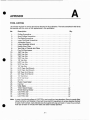
TABLE OF CONTENTS
SECTION 1: INSTALLATION
Specifications and Requirements
Installation
Important Safety Instructions
Initial Power-lip
1-1
1-1
1-3
1-3
SECTION 2: PREVENTATIVE MAINTENANCE
Introduction
Maintenance Procedures
Periodic Lu brication
2-1
2-1
2-2
SECTION 3: SYSTEM OVERVIEW
•
Operational Assemblies
Operational Modes
Drive Train Subsystem
Speed Sensing Subsystem
Speed Control Subsystem
Torque Subsystem
The Display Module
3-1
3-2
3-4
3-4
3-5
3-6
3-6
Electl'ical Subsystem
3-7
1nt marional Consideration. .
3-11
SECTION 4: SYSTEM CHECKOUT
Power Up Diagnostics
Diagnosis and Repair
Field Service Diagnostics
Diagnostic Test Description
Calibration
Display Module Test Points
Checking the Power Supply
•
4-1
4-3
4-6
4-6
4-10
4-13
4-13
e
SECTION 7: EXPLODED VIEW DRAWING AND PARTS LIST
Pan Ordering InfOlmation
7-1
APPENDIX
Tool Listing
Torque Specification
e·
A-I
A-2
•
e
iii
, - - - - - - - - - - - - - - - - - - - - - - - - - - - - - - -
•
SECTION
SPECIFICATIONS AND REQUIREMENTS
INSTALLATION
Physical:
Installation Area Requirements
Overall Dimensions:
22.5" wide x 55" long
•
1
INSTALLATION
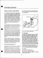
Before unpacking and installing The BIKE, its
location should be determined. The selected site
should meet the following requirements;
x 62.75" high
Ceiling Height Minimum Requirement:
7' (2.1m)
•
The mounting surface should be level, dry,
even and clean.
Note: Extremely tall individuals may require a
higher ceiling.
•
If carpeting is used, a high density type is
recommended.
Recommended Minimum Installation Area:
3' (O.9m) wide x 5' (1.5m) long
•
The installation area should be free of dust.
•
The unit should not be operated in highvibration environments.
The BIKE's Display Module is equiped with a
POLAR'M Heart Rate Monitor receiver. To reduce
the possibility of signal interference between
heart rate monitor users, no other transmitters
should be within a four foot radius of the Display
Module.
•
All cabling must be routed out of traffic areas
and passageways.
•
Maximum Weight of The BIKE and Rider:
530 pounds (241 kg)
Do not allow foreign objects or liquids to enter the internal portion of the equipment.
•
The area should be well lit while the equipment is in use.
Static Floor Loading:
79 Ibs.l sq. ft. (3780 Pa)
When a satisfactory location has been decided
upon. The BIKE can be unpacked and installed.
Remove the pendUlum restraint strap located
along the left side of The BIKE. Grasp the pendulum restraint strap and pull downward.
Electrical:
Input Voltage:
90 to 264 Volts AC
CAUTION: The pendulum restraint strap must
be removed before operating
The BIKE.
Input Frequency:
50/60 Hertz
Power Requlrem.ent:
65 Watts, maximum
Position the cycle in the desired location. Rotate
the right front (eccentric) caster so that The BIKE
is stable.
Power Entry Fuse:
250 VAC, 1 Amp, TYPE 2AG
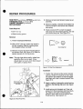
Make certain that the ONIOFF switch, situated
on the Power Module which is located at the right
front of the unit frame, is in the 0 (off) position.
Connect the AC power cord to the appropriate
connector of the Power Module (see Figure 1.1).
Input Circuit Current Requirement:
15 Amp line, minimum
•
Number of Daisy-Chained Units per
15 Amp Line:
5, maximum
1-1
•
INSTALLATION
IMPORTANT SAFETY INSTRUCTIONS
INITIAL POWER-UP
When using The BIKE, basic precautions should
always be followed, including:
After properly installing and grounding The BIKE,
it is ready to be turned on.
Read the entire Owner's Manual before
using The BIKE.
CAUTION: Ensure that the pendulum restraint
strap has been removed. DO NOT
pedal The'BIKE during the PowerUp procedure. Wait until the CYBEX
logo appears in the LED Display
before pedaling.
DANGER: To reduce the risk of electric shock:
•
Always unplug The BIKE from the electrical
outlet before cleaning.
To power the unit, turn the ON/OFF switch which
is located on the Power Module to its 1 (on) position. Three events occur:
WARNING: To reduce the risk of burns, fire,
electric shock or injury:
•
•
Use the The BIKE as described in the Owner's Manual. Do not use attachments not
recommended by CYBEX.
•
Never operate this unit if it has a damaged
power cord or plug, if it is not operating properly, or if a liquid has entered it.
•
Keep the power cord out of traffic areas and
away from heated surfaces.
•
Never operate this unit with the air vents
blocked. Keep the air vents free of lint, hair
and the like. Do not drape towels over the
Display Module.
•
Never drop or insert any object into any
opening.
•
Do not use outdoors.
•
To disconnect, set the ON/OFF switch to the
o (off) position. then remove the plug from
the outlet.
•
Obtain medical clearance before beginning
any exercise program, and never over-exert.
1. A system diagnostic is performed to verify that
all devices are functioning properly.
If the diagnostics are unsuccessful, a big "X"
appears in the LED Display and an error code
appears in the Message I Data Display. Refer
to Section 4: System Checkout.
2. A torque baseline calibration procedure is executed at the conclusion of a successful diagnostic check.
If the diagnostic test is unsuccessful, the
torque baseline procedure is not initiated. Refer to Section 4: System Checkout.
3. The Initial State is entered.
Initial State
While in its Initial State. The BIKE is sitting idle
waiting for the user to select an exercise mode.
The Initial State is characterized by the CYBEX
logo scrolling on the LED Display and the message "SELECT MANUAL, PROFILE OR RACE" in the
Message / Data Display.
•
~
1-3
•
SECTION
marks may require a mild abrasive. Under no circumstances should a solvent be used on any
plastic parts. Permanent damage to the plastic
will result.
INTRODUCTION
The BIKE has been designed to require an absolute minimum of periodic maintenance. Common
non-abrasive household cleansers can be used
to clean external parts. All of the bearings are
sealed and lubricated for life. There a e no user
adjustments required.
Cleaning the Display Module
Apply an approved cleanser to a soft cloth and
wipe the surface clean. Do not spray cleaner directly onto Display Module.
All BIKEs are calibrated at the factory so field
calibration should not be required under most
circumstances. The calibration procedure should
only be needed when the BIKE's accuracy must
be verified. Refer to Section 4: System Checkout
for the calibration procedure.
•
2
PREVENTIVE MAINTENANCE
Note: Avoid spraying liquids into vent openings.
CAUTION: DO NOT use any abrasive or mildabrasive cleansers on the Display
Module.
MAINTENANCE PROCEDURES
EVERY THREE MONTHS
DAIL Y MAINTENANCE
1. Remove the left side enclosure as described
in Section 5: Repair Procedure, Enclosure
Removal.
The following cleansers applied to a clean, soft
cloth may be used for cleaning.
•
isopropyl alcohol
•
glass cleaner
•
general
•
ammonia'
purpos~
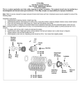
2. Inspect the chain for a "dry" condition, little or
no lubricant present
a. If chain is dry. lubricate the chain using a
light household oil, such as 3 in 1. Apply
oil sparingly since any excess will get dispersed about the interior.
liquid cleanser
• Diluted according to manufacturer's recommendarions.
3. Check the surface of the flywheel on which
the resistance belt rides. If there is an accumulation of dirt or deposits. they can be removed as follows:
Do Not Use the following cleansers for cleaning
the display module or any plastic parts.
•
•
abrasive cleanser
•
mild abrasive cleanser
•
ethyl alcohol
•
methyl alcohol
•
acetone
b. Turn power off (0) then on (1). This will
relieve the tension on the belt. When the
motor stops running, turn power off (0).
C. Slide the resistance belt off the flywheel.
CAUTION: Do not bend, crease or twist the belt.
The BIKE's exterior should be cleaned once a
day to preserve its appearance. Wipe down the
frame using a soft cloth dampened with an approved cleanser. The plastic enclosure, hand
grips and seat can be cleaned in the same manner. Stains and scuff marks may be removed
with a more aggressive cleanser. Stubborn scuff
d. Carefully apply 240 grit or finer sandpaper to the flywheel circumference while
slowly turning the left pedal.
2-1
•
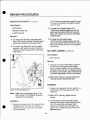
PREVENTIVE MAINTENANCE
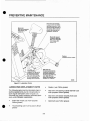
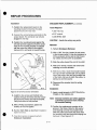
Idler lever arm bearings:
Located in both the left and
right idler lever arms. Lubricate the outside diameter of
the bearing. Refer to the exploded view drawing, item
numbers13, 14 and 73.
Detent pin:
Refer to the exploded
view drawing, item
number 34.
Chain Idler mount:
Located on right side.
Refer to the exploded
view drawing, item
number 126.
Casters:
Located at all four corners.
•
Idler lever arm
Tension bracket pivots:
Located at the junction of
the tension bracket and
the left and right idler lever
arms. Refer to the exploded view drawing, item
numbers 13. 14 and 15.
00030
Figure 2.1 Lubrication Points.
•
LUBRICATING REPLACEMENT PARTS
•
Casters (use Teflon grease)
The following parts must be lubricated when installing replacements, but do not generally require regular lubrication (refer to figure 2.1).
Lubricate only under conditions described previously under Periodic Lubrication.
•
Idler lever arm bearing outside diameter (use
mulli-purpose Lithium grease)
•
Idler lever arm tension bracket pivots (use
mulli-purpose Lithium grease)
•
Chain idler mount (use multi-purpose
Lithium grease)
•
Detent pin (use Teflon grease)
•
Thrust bushing (use multi-purpose Lithium
grease)
2-3
•
SECTION
3
SYSTEM OVERVIEW
OPERATIONAL ASSEMBLIES
mines the amount of resistance or torque at the
pedals.
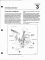
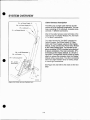
The BIKE's basic operational assemblies include
the crank, flywheel, resistance belt, belt tensioning mechanism, pendulum, power supply and
Display Module, as shown in Figure 3.1. When
The BIKE is pedaled, the crank turns the castiron flywheel, via a chain drive. A fabric belt is
wrapped around the flywheel and when tensioned, provides braking action on tile flywlleel.
This in turn, produces resistance to the pedaling
operation, or torque. A D.C. Gearmotor, controlled by the Display Module, adjusts the tensioning mechanism by moving the position of a
cam which presses on the belt. This action deter-
For ease in diagnostics and repair, The BIKE's
basic operational assemblies are grouped by.
function into subsystems: they include, drive train
(flywheel, freewheel and crank), speed sensing
(Hall effect board and magnets), speed control
(belt tensioning mechanism and D.C. Gearmotor), torque (Pendulum and optical encoder),
the Display Module, and the electrical subsystem
(power supply, cable harness and power entry
module).
\
For subsystem diagnostics. refer to Section 4:
System Checkout.
Display Mcdu!e
•
Cam
Flywheel &
Resistance
Belt
Hall Effect Board
Crank
Pendulum
Belt Tensioning
Mechanism
•
00112
Figure 3.1. Basic Operational Assemblies.
3-1
•
SYSTEM OVERVIEW
The LED display forms two concentric laps. The
outside lap represents the rider and the inside
lap represents the pacer. Each lap is 1/10 of a
mile or 1/10 kilometer, with the starVfinish line
located at the bottom center of the LED window.
Immediately upon selection of the Race mode,
one LED in each lane will appear at the start line.
As the race begins, these LEDs travel through
the laps, reflecting the contestants' current positions, based upon their individual distances traveled.
the LED display with a level 8 work load. Each
LED represents 25 Watts. At level 8, he maximum workload will be 225 Watts (nine LEDs in
height) and the minimum will be 50 Watts (two
LEDs in height).
After all profile mode parameters are entered, the
chosen profile, with proper effort level scaling, is
shown on the LED display. During the exercise
session, the system adjusts the resistance from
stage to stage, based on the profile and its effort
level. The setting of the resistance starts when
the rider begins pedaling above 30 RPM. The
current stage in the profile is indicated by that
column of LEDs blinking.
The rider's speed will depend on the gear selected (as a constant resistance setting) and the
pedaling' speed. The gear level determines the
torque setting maintained by the resistance belt.
The pacer's speed is preselected by the rider.
Submax Test
•
The Submax Aerobic Test is a measure of the
rider's response to sub-maximal work. It receives heart rate information at various work
rates and then predicts the rider's maximum ability to consume oxygen (max V02) as well as
maximum work capacity, maximum MET level
and maximum calories per hour.
The software in the Submax Test provides the
appropriate work load (at constant power), based
upon the rider's heart rate response to the exercise and then establishes the relationship between work load and heart rate.
Figure 3.4 Typical Race Mode Display
The rider's heart rate is measured externally and
entered via the keypad.
Race Mode
The Race mode is an exercise session where the
rider races against a pacer. The distance of the
competition and the pacer speed are selected by
the rider. The system will maintain a constant resistance (unlike Manual or Profile mode) and display the racers' positions throug~lout the entire
session.
•
Anaerobic Test
The Anaerobic Test is a measure of the rider's
peak power and endurance. This test has the
rider exercise at a constant resistance for 30 seconds. The BIKE records the rider's total power
production at every five second interval as well
as the total power production for the full 30 second period.
The race starts after all the parameters are entered and the rider presses the START key. The
Vacuum Fluorescent Display (VFD) shows the
remaining distance for both the rider and the
pacer along with the distance that the rider leads
or trails the pacer (in units of hundredths of a
mile/km).
Upon entering the Anaerobic Test, the rider's
body weight is entered via the keypad. This body
weight determines the resistance setting (in constant resistance mode) that will be used during
the exercise.
3-3
•
SYSTEM OVERVIEW
ing tension on the belt, as shown in Figure 3.5.
The D.C. Gearmotor moves the tension bracket
via a threaded rod.
SPEED CONTROL SUBSYSTEM
The Tension Bracket Assembly is adjusted by a
D.C. Gearmotor coupled to a threaded control
rod by a flexible coupling. The coupling compensates for any misalignments between the motor
shaft and control rod. When the motor turns, it
rotates the threaded control rod. A translating
plastic nut, called the rod pivot, travels up and
down the control rod, depending on the direction
of motor rotation. Tension arms attached to the
rod pivot are connected to the ends of the cam
idler arms. This action pushes or pulls on the
idler arms to pivot the cam and adjust belt
tension.
•
On initial startup, the motor drives the tension
bracket assembly down toward the minimum belt
tension position. At the end of travel, the rod
pivot encounters a compression spring. As the
rod pivot continues dri ing, the spring compresses a a pain wher the
tor stalls. The
Display Module de'ects this co di'ion through a
rise in motor current. A preset current threstlold
is reached and the motor shuts off and then reverses, driving the control rod in the other direction. It continues to run in this up direction for a
short period of time and then shuts down. The
tensioning mechanism and the belt tension are
now at a low resistance position: the starting
position.
00113
Figure 3.5 Belt Tensioning Mechanism.
D.C. Gearmotor
The rotary motion needed to spin the control rod
is provided by a permanent magnet D.C. Gearmotor. The 12V Gearmotor receives its power
from the CPU Board in the Display Module. The
CPU Board sends power pulses of varying
lengths, depending on the amount of resistance
change required. The direction of rotation and
the length of the power pulses are determined by
the CPU Board after assessing the pendulum
angle, the speed of the flywheel, and the mode
of operation. Gearmotor direction is reversed by
changing the polarity of the motor supply voltage.
When The BIKE is pedaled in its Initial State
(With the CYBEX logo display), it increases belt
tension until a small amount of torque is measured. This is referred to as the minimum resistance position. All subsequent tension positions
are based on this reference location.
Belt Tensioning Mechanism
•
TIle Gearmotor connects to the frame via a
bracket isolated by rubber shock mounts. These
shock mounts, along with the flexible coupling,
keep motor vibration and noise to a minimum.
The purpose of the belt tensioni g mechanism is
to tighten the ric ion belt arou d the flyWheel in
order to develop braking torque 0 resis ance.
The tighter the belt wraps around he flywheel
the more torque is produced. This belt tensioning
is produced by a mechanical linkage and an eccentric cam idler. During operation the tension
bracket assembly is pushed or pulled causing the
cam to pivot into the belt, increasing or decreas-
Termination
22 AWG stranded insulated wire.
Red wire to pin 1, Black wire to pin 2
Red wire positive, Black wire negative = Clockwise
rotation facing shaft end.
.
3-5
•
SYSTEM OVERVIEW
LED Display Board
Speaker
The 16 x 30 LED array on the Display Board is a
major part of the Display Module. The Display
Board is passive and is completely controlled by
the CPU Board. The 40-pin connector, J 1, sends
all power (+5V) and control signals to the Display
Board.
The CPU Board contains a piezoelectric audio
transducer which produces tones. This lowpower device is used primarily to produce a short
tone each time a valid keypad input is received,
giving the user feedback.
Keypad and Overlay
ELECTRICAL SUB-SYSTEM
The entire front of the Display Module is covered
by a coated graphics overlay assembly. This
overlay contains filters for the LED and VFD display areas. In addition. the keypad assembly is
integrated into this overlay. User input to the Display Module is via this keypad.
•
Power Supply
The BIKE utilizes an industry standard 40 Watt,
universal input, triple output switching power supply. This automatically operates over a universal
range of input AC line power and produces the
DC voltages required by The BIKE. No jumpers
or switches are needed to select input line voltage.
The keypad is a flat, non-tactile membrane
switch assembly. The graphics layer on the overlay indicates the active key areas. Approximately
12 ounces of force are needed to activate a key.
The CPU Board's audio transducer is used to
indicate when a keystroke has been detected,
since there is no tactile feedback (motion under
an active key area is only a few thousandths of
an inch).
The power supply is UL, CSA, and VDE approved for compliance with safety and electromagnetic emission standards.
Specifications
Type:
40 Watt universal input, triple
The keypad assembly also contains a separate
ESD shield layer. This electrically conductive
layer is used to ground any high-voltage electrostatic discharge (ESD) pulses, produced when a
statically charged person hits the keypad. This
prevents most of the high-voltage discharge
from reaching the CPU board.
output, open frame switching
power supply.
Input:
AC Voltage:
Frequency:
EMI:
The outer layer of the overlay contains a
hardcoat finish to protect it against minor scratching and cleaning chemicais. Only use cleaning
agents recommended by CYBEX to clean the
overlay and do not use anything abrasive to wipe
it (see Section 2: Preventative Maintenance for
cleaning instructions).
•
90-264 VAC
47-63 Hz
Meets or Exceeds FCC
CLASS B
Leakage Current: 600 lUi @ 132 VAC Maximum
Input Fuse:
2 AMP. 250 Volt
3-7
•
SYSTEM OVERVIEW
P4 -to Power Supply, Jl
Cable Harness Description
"\
\
P2 -to Power Supply, J2
The BIKE uses a single cable harness to interconnect all of its electrical components. This harness, consisting of 18 individual, insulated wires,
connects 11 different connectors.
\
\
\
P3 - to Ground
\
P1 -to Display Module .
Most of the cable harness wires terminate at the
connector for the Display Module (P1), the heart
of The BIKE's electronics.
The cable harness for The BIKE connects the
Optical Encoder, Hall Effect Board, DC Gearmotor and Power Supply outputs to the Display
Module, It also connects the Power Entry Module
to the Power Supply input. The harness is one
piece consisting of 300V insulated wire attached
to eleven connectors. The main connector, (P1),
terminating at the Display Module, is a 25 pin D
connector. It incorporates thumb screws to easily
attach or remove the connector from the Display
Module without using tools. The other connectors
either have high insertion force or locking ramps
to insure tight connections.
•
See Figure 3.6 and refer to the chart on the next
page.
I
/
~P
-
'- P9
Pl0
i
00025C
Figure 3.6 Cable Harness Replacement.
•
3-9
•
SYSTEM OVERVIEW
NEMA 5-15P
•
00120
Figure 3.7 Power Distribution.
Power
INTERNATIONAL
CONSIDERATIONS
The power supply used on The BIKE is an industry standard 40 Watt, triple output, universal input, switching power supply. The 90/264 VAC,
47/63 Hz universal input eliminates the need fo~
an external 115/220 VAC switch. Refer to the
Power Supply subtopic for a complete specification and description of the power supply unit.
From its inception, The BIKE was designed to be
an international product. That is why the only differences between U.S. domestic and international versions of The BIKE are the languages
used. Great pains were taken by CYBEX to ensure international compatibility, as in the power
supply selection.
Electrical Wiring Considerations
The BIKE's power input cord was chosen with
forethought for international use. As a result, a
universally standard female input, used commonly for computers, computer printers and peripherals, was selected. The male adapter
supplied is standard for U.S. power sockets.
However, other male adapter styles should be
readily available in the country of interest.
The BIKE uses the following conventions for internal AC wiring:
AC HOT
AC NEUTRAL
CHASSIS GROUND
•
Black wire.
White wire.
GreenlYellow stripe
wire.
Both the HOT and NEUTRAL lines are switched
by the Power Entry Module.
3-11
•
SYSTEM OVERVIEW
SOFnwARECONSIDERAnONS
There are a total of eight different language versions (seven languages) of the Display Module.
The only physical difference is the EPROM (software versions) and the Keypad/Overlay (with legends unique to each language).
English for all versions of the program.
COLOR
36708699
White
----------------Black
36705699-1
White
DEFAULT
MEASUREMENT
SYSTEM
English 8ystem
3670S699-EJM
----------------36708699-1 ElM
Black
Metric System
French
36705699-F
White
-----1-----------3670S699-1F
Black
Metric System
Ger a
3670S699-D
White
-----1-----------3670S699-1D
Black
Metric System
3670S699-1
White
-----1-----------3670S699-11
Black
Metric System
English I Metric
•
Note: The Field Service Diagnostics appear in
DISPLAY MODULE
PART NUMBER
LANGUAGE
English I Non Metric
The software program in all versions is logically
identically. The only difference in each program
is the language of the user prompts and the default system of measurement.
Italian
Japanese (Kalakana)
Spanish
3670S699-J
White
-----1-----------36708699-1 J
Black
3670S699-E
White
----------------3670S699-1E
Black
Swedish
....
3670S699-8
White
3670S699-1 S
Black
----------- ------
•
3-13
Metric System
Metric System
Metric System
•
SECTION
4
SYSTEM CHECKOUT
Timer Tests - Bit 1,2,3
(Error Word Value = 2, 4, 8)
POWER UP DIAGNOSTICS
The Power Up tests for the The BIKE's CPU
Board are broken into two parts. A failure in the
first part, the Module Check, indicates that the
CPU Board has a fault and the Display Module
should be changed. A failure in the second part,
the Peripherals Check, means that there can be
a problem with the CPU Board, the system cable
harness, an internal Display Module connection
or one of the peripherals. In this case, the Field
Service Diagnostics should be run to isolate the
problem.
•
There are three internal timers which are set up
to count down and generate interrupts at specified time intervals. These provide all timing operations for the CPU Board.
For this test, the three counters are initialized
and start counting down. As each timer counts
down to zero, it causes an interrupt and the appropriate bit is turned off in the error word, indicating correct operation. These bits are:
When The BIKE is first turned on, the Power Up
tests are run. These tests return their results to
the main executive program as an Error Word.
This Error Word value is originally set to all 1 's
(hexadecimal value = FF). As each test runs successfully, the corresponding bit is turned off in
the Error Word (set to 0). If all Power Up tests
run successfully, the Error Word becomes zero.
If not, the main executive program sees a nonzero value in the Error Word and a large X appears on the LED display while the Error Word
value is written to the VFD. The Error Word is
displayed as a hexadecimal value (1 - FF). To
clear the error condition and resume BIKE operation for troubleshooting. press the Stop key.
Bit 1 = Timer 0 Test (Error Word Value = 02)
Bit 2
=Timer 1 Test (Error Word Value = 04)
Bit 3
= Timer 2 Test (Error Word Value = 08)
PerIpherals Check Tests
A failure in any of the following tests indicates a
fault in either the CPU Board, internal Display
Module cable connections, the peripheral itself or
the system cable harness:
Motor Stall Test - Bit 4
(Error Word Value
= to)
Module Check Tests
For this test, the motor is turned off and the
MOTOR STALL bit is read back. It should be
high indicating the motor is not in the stalled condition. If this bit is low, an error is indicated. This
error would normally be caused by a faulty CPU
Board.
A failure in any of the following tests indicates a
faulty CPU Board and requires replacing the Display Module:
RAM Test - Bit 0
(Error Word Value
= 01)
Keyboard Interface Test - Bit 5
(Error Word Value = 20)
The 32K SRAM is tested with a simplified walking
1 's and O's pattern. This bit pattern is written to
the RAM and then read back. If the wrong value
is read back, an error is generated. This is the
first code executed upon power up.
For this test, the CPU checks the READ KEYPAD port for data. There should be no keystroke
pending. If there is keypad data, it is an error.
This can indicate either a faulty CPU Board, a
faulty keypad or a faulty keypad ribbon
connector.
ROM Test - Bit 7
(Error Word Value=80)
••
The 64K program EPROM is tested by calculating its basic checksum. If this error is reported
(Error Word = 80), replace the Display Module.
4-1
•
SYSTEM CHECKOUT
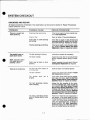
DIAGNOSIS AND REPAIR
All repair procedures mentioned in the chart below can be found in Section 5: Repair Procedures
unless otherwise noted.
•
PROBLEM
POSSIBLE CAUSE
REPAIR PROCEDURE
There is a rough feel
while pedaling.
Pedal bearings are binding.
If the feel is rough on only one pedal, perform Pedal Replacement.
Ctlain is "dry."
Refer to Section 2: Preventive Maintenance.
Chain idler or crank bearings
are binding.
If the feel is rough in both forward and
backward pedaling, inspect the chain idler
and crank bearings. Replace as needed.
Flywheel bearings are binding.
If the feel is rough in only forward pedaling, perform Aywheel Bearing and Spacer
Replacement. Repair or replace as needed.
The idler bushing is sticking.
Lubricate or replace as necessary.
The chain is loose.
Inspect the chain idler for a faulty tension
spring. Replace tension spring if necessary.
Tooth may be bent on drive
sprocket.
Inspect sprocket for bent tooth. Perform
CranklSprocket Replacement as required.
The belt may have slipped off
of he fIYlf.' eel.
Slide belt back into flywheel groove.
The bel is broken.
Inspect the friction belt. Perform Friction
Belt Replacement as required.
The pedals jump on
each down stroke.
Note: See also "There
is a rough feel while
pedaling." above.
There is no resistance.
The tension
stripped.
•
pivot
rod
is
If the motor turns freely but the mechanism does not move, perform Rod Pivot,
Spring, Threaded Rod and Thrust Bushing Replacement. Repair or replace as needed.
The belt tensioning mechanism is binding.
Loosen the flex Goupling at the motor.
Turn the threaded rod, if the rod will not
turn; perform Rod Pivot, Spring, Threaded
Rod and Thrust Bushing Replacement If the
threaded rod itself is free but the rest of
the mechanism binds, perform Pendulum
Hub Bearing and Idler Lever Arm Bushing Replacement. Repair or replace as needed.
The motor, Hall Effect Sensor
board or Display Module have
failed.
Perform the Field Service Diagnostics in
this section. If the motor does not move
during the test, check for the presence of
+ and -12V at the motor connector while
using the diagnostics test. If voltage is
present perform D.C. Molor Replacement.
Otherwise replace the Hall effect Sensor
board or Display Module as required.
4-3
•
SYSTEM CHECKOUT
PROBLEM
POSSIBLE CAUSE
REPAIR PROCEDURE
The displays (LED and
vacuum fluorescent)
are not operating
properly.
Either the Display Module or individual elements have failed.
Perform Field Service Diagnostics to verify an LED or VF failure. Replace the Display Module if necessary. Perform Display
Module Replacement.
The unit does not reo
spond to keypad com·
mands.
Either the Display Module or
keypad have failed.
The display does not
register the correct
A Hall E·fect Magnet· as falle
of.
RPM.
A Hall Ef ect Sensor board is
faulty.
•
The System Cable Harness
has failed.
•
Perform Field Service Diagnostics if pos- .
sible to verify which key is failing. Verify
that Display Module is Rev. C or better.
Replace the Display Module if necessary.
Perform Display Module Replacement.
Inspect the flywheel for the presence of
two magnets. Perform Hall Effect Magnet
Replacement.
Periorm the Field Service Diagnostics in
this section. If, while rotating, the display
does not toggle between 1 and 0 as each
magnet passes by the sensor board, perform Hall Effect Sensor Replacement. If the
display toggles between 1 and 0 for only
one 0 the magnets, replace the faulty
magnet. Perform Hall Effect Magnet Re·
placement.
Check System Cable Harness for loose
connections, shorts to the frame and continuity between the Hall Effect board connector and the Display Module.
The Display Module has failed.
Replace the display Module. Perform Dis·
play Module Replacement.
Testing does not start.
A Hall Erect Sensor board is
faul y.
Perform the Field Service Diagnostics in
this section. If, while rotating, the display
does not toggle between 1 and 0 as each
magnet passes by the sensor board, perform Hall Effect Sensor Replacement. If the
display toggles between 1 and 0 for only
one of the magnets, replace the faulty
magnet. Perform Hall Effect Magnet Re·
placement.
Heart rate monitor receiver has been determined to be source of
heart rate monitoring
problems. (Refer to
The BIKElThe SEMI
Owner's Manual for
troubleshooting the
heart rate monitor
transmitter.)
T e conneclio between t e
heart ra e monitor receiver and
• e Display Module CPU board
has come loose.
Perform Display Module Replacement, check
receiver connection, reinstall Display
Module.
Receiver is inoperable.
Perform Display Module Replacement
4-5
•
SYSTEM CHECKOUT
Checking the Belt Tensioning Mechanism
Tach Test
The tach test verification operation shows the
function of the Hall Effect Board and the magnets
on the flywheel. When the tach test is selected,
the VFD shows the following:
The tension bracket assembly's action should be
a smooth, continuous motion throughout its
range of travel. If it is not, check that the D.C.
Gearmotor is working properly (see D.C. Gearmotor below). Check that the control rod is freely
rotating without binding. Check for proper adjustment of the flexible coupling by grasping the rod
and gently pushing fore and aft (parallel to the
control rod). No play should exist in this area.
Check for adequate lubrication on the thrust
bearing and washers. If binding or roughness is
detected, inspect the threads in the rod pivot. Replace the rod pivot it moiion is not smooth and
continuous while rotating slowly by hand.
••
prOfiles~ ~
I
STOP TO EXIT
TACH TEST
I
During the test, rotating the flywheel slowly
causes the TACH VALUE to toggle between 1
(no magnet near the Hall Effect Board) and 0
(magnet close to the Hall Effect Board) as each
of the two magnets on the flywheel passes the
Hall Effect Board. No change in the TACH
VALUE while the flywheel is rotating indicates a
faulty Hall Effect Board, faulty or missing magnets or poor alignment of the board and magnets. Should the TACH VALUE fail to change as
one of the two magnets passes by the Hall Effect
Board, the magnet may be faulty or missing.
The bracket arms should not contact any other
parts. Eliminate any interference with adjacent
parts by gently bending the appropriate part. Axial play between the tension bracket weldment
and the rod pivot can be checked by grasping
the bracket and gently pushing fore and aft (parallel to the control rod). The relative motion between the bracket and the rod pivot should not
exceed 3/32". If it does, replace the tension
bracket weldment.
Note: The TACH VALUE automatically reverts
from 0 back to 1, even if a magnet remains
close to the Hall Effect Board.
Checking the D.C. Gearmotor
•
wm~CtJ
TACH VALUE:: 1
Encoder Test
The motor should run smoothly while cycling up
and down. If binding or roughness occurs, disconnect the flexible eouolina from the Gearmotor
output shaft. Run the Motor Test again vJhile
squeezing the motor shat be Neen your fingers.
The motor should run freely and not stall easily.
Check that the motor runs in both directions. If it
does not run at all, or in one direction only, unplug the motor leads and attach a DVM with the
negative lead at pin 2. Run the Motor Test. A
reading of +12 volts (CW) or -12 volts (CCW)
should be obtained. If voltage readings are correct. replace the motor. If voltage readings are
not correct, check the Display Module and the
System Cable Harness.
The encoder test verifies the encoder operation
by displaying a value corresponding to the pendulum angle. This test is also used to check the
pendulum's operation. When the encoder test is
selected, the VFD is similar to the following:
PrOfiles£
(
~
~ ~
Gj
ENCODER VALUE:: 0
PRESS 0 TO CLEAR
STOP TO EXIT
(WaKIIIIt)
4-7
W
~
(~)
~
I
- - - - - - - - - - - - - - - - - - - -
•
SYSTEM CHECKOUT
LED Test
Profilest!:1
The LED test is used to check the function of the
LED display. When the LED test is selected, the
VFD shows the following:
prOll!eS~ ~
I
W
)
~=---==---==----=~
EO,kRa,o)
~
(Dist'Ca)
W
~
LS!\ Q
During the test, every pixel of each of the two
rows of 40 display elements is lit. They remain lit
until Stop is pressed to exit the test.
~ ~ ,Ran:"",
LED TEST
PRESS STOP TO EXIT TEST
~
If one or more pixel does not respond, replace
the Display Module. Refer to Display Module
Replacement in Section 5: Repair Procedures.
~
Beep Test
•
•
Each column of LEOs light and stay on, one at a
time, from left to right, until the entire screen is lit.
Then each column turns off, one at a time, until
the display is blank. The process is repeated until
Stop is pressed to exit the test.
The beep test is used to check the function of the
sound module. When the beep test is selected,
the VFD shows the following:
prOII!eS~ ~
If one or more column of LEOs does not respond, replace the Display Module. Refer to Display Module Replacement in Section 5: Repair
Procedures.
W
~
Lr!l Gj
PRESS ENTER TO BEEP - PRESS STOP TO EXIT
7 BEEP TEST
VF (Vacuum Fluorescent) Display Test
During the test, press Enter to generate a beep
tone. Press Stop to exit the test.
The VF test is used to check the function of the
vacuum fluorescent display VFD. When the VF
test is selected, the VFD resembles the following:
If no "beep" is heard, replace the Display Module.
Refer to Display Module Replacement in
Section 5: Repair Procedures.
4-9
•
SYSTEM CHECKOUT
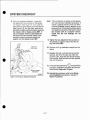
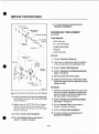
8. If the unit requires calibration, loosen the
two adjustment lock-screws on the pendulum suppor . See figure 4.3. If the LED Display shows lit LEDs above the horizontal line
(see Figure 4.2), turn the Allen screw in the
pendulum weight counterclockwise (lowering
the weight) until the display shows SET. If
the LED Display shows lit LEDs below the
horizontal line. turn the Allen screw in the
pendulum weight clockwise (raising the
weight) until the display shows SET.
Adjustment
9. Tighten the two adjustment lock-screws on
the pendulum support. Ensure that the display still shows SET.
10. Remove the 2 kg calibration weight from the
spring.
11. Reattach. the belt: route the belt around the
flywheel, but off to the side and under the
eccentric cam. Hook the free end of the belt
to the spring. Slide the belt onto the flywheel
and into the groove.
•
0
,.
IIV
I
~.
~
12. Press [STOP] followed by
and [ENTER]
to end the calibration procedure and exit the
Field Service Diagnostic Program.
Pendulum Weight
Allen Screw
13. Reinstall the enclosure; refer to the Enclosure Installation procedure in Section 5:
Repair Procedures.
00026C
Figure 4.3 Pendulum Adjustment Screws.
•
Note: There should be no tension on the pendulum hub during the calibration procedure. If
weight is applied and the unit is not "SET, "
the most probable cause is tension on the
pendulum hub. Check that the friction belt is
not caught on any part of the frame. Check
the encoder belt for excessive tension.
Check that the hub bearings are not
binding.
4-11
•
SYSTEM CHECKOUT
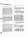
DISPLAY MODULE TEST POINTS
CHECKING THE POWER SUPPLY
If a problem with the Display Module is suspected, several test points are provided on the
CPU Board to aid in troubleshooting. To access
these test points. remove the Display Module
from the tube. but do not disconnect the
25-pin D connector from the cable harness.
Before testing the power supply, check the
Power Entry Module fuse and replace if necessary. Check that AC power is available at the
Power Entry Module.
CAUTION: Always remove AC power from
The BIKE before attempting to service the Power Supply. The Power
Supply contains dangerously high
voltages.
Supporting the Display Module face-down on the
handlebars, part of the CPU Board is accessible
through the opening for the mounting bracket.
Several test points are available with silkscreened legends, as shown in Figure 4.4.
1. Refer to the Power Supply Replacement
procedure in Section 5: Repair Procedures
to remove the power supply.
These test points are as follows:
•
Legend
Location
Description
5V
12V
GND
TACH
C34
C39
C34
R20
CURSENS
R12
+5V power supply
+ 12V power supply
Ground
Tachometer pulses
from Hall Effect Board
Motor current sense
voltage (1.0 Volt/Amp)
Pull the assembly out of the tube and rest it
on the handlebar mount. Visually check the
supply for obvious component failures.
3.
Remove the 6 pin output connector.
4. Turn on the power switch.
5. Check for proper AC voltage at connector J 1
on the power supply board.
Notes: The + 12V supply can rise to over 13 Volts
when the motor is not on.
The tachometer pulses at R20 are unlatched, directly from the Hall Effect Board.
This point should normally be a logic high
unless a flywheel magnet is near the Hall
Effect sensor.
The motor current sense produces a voltage equivalent to 1.0 vol amp. When the
motor is under slight loading (at low, decreasing belt resistance), the current can
be under 100 mA (0. 1V). When the motor
stalls, the current can be 2.0 amps (2.0V) or
higher.
•
2.
6. Check for proper output voltages at J2 on
the power supply board.
Note: Output voltages may not be within regulation limits when tested under this no-load
condition.
Common - pins 4 & 5
+5 volts - pins 2 & 3
+ 12 volts - pin 1
-12 volts - pin 6
4-13
7. If no power is available at J2, check voltage
across the power supply fuse. If voltage is
present, the fuse has blown and the power
supply must be replaced.
•
SECTION
5
REPAIR PROCEDURES
ENCLOSURE REMOVAL AND INSTALLATION
(White: Right pIn 367PE194. Left pin 367PE 195
Black: Right pIn 367PE194-1. Left pIn 367PE195-1)
WARNING: When performing any of the following procedures with the enclosure removed. exercise
extreme caution when working with moving parts.
Tools Required
5. Position the right side crank so that it is parallel with the slot in the enclosure .
• Phillips screwdriver
CAUTION
6. Remove the four 9/16" Pan-L screws securing the right side enclosure. Remove the
right side enclosure. See Figure 5.2.
Always remove the left enclosure first.
Removal
Installation
1. Turn the power to the unit to the 0 (off) position and remove the power cord from the
wall outlet.
1. Position the right side crank so that the slot
in the enclosure passes over it.
2. Position the left side crank so that it is parallel with the slot in the enclosure.
•
2. Lift the right side enclosure into position.
Loosely reinstall the four 9/16" Pan-L
screws used to secure the right side enclosure. Push the enclosure. ensuring that the
gasket seals against the main tube. Snug
tighten front enclosure screws. Snug tighten
other screws. See Figure 5.2.
3. Remove the six 9/16" Pan-L screws securing the left side enclosure. Lift the left side
enclosure off. See Figure 5.1.
Note: Do not over-tighten the Pan-L screws.
Doing so could damage the fasteners.
Pan-L scrows (6 places)
11-:
:
Pan-L screws (4 places)
I
I
j
f
Rotate crank so that it is
parallel 10 the slot in
Enclosure.
0OOO2C
Figure 5.1 Left Side Enclosure.
•
4. Squeeze the front and rear of the bottom
bellows ring together and remove bellows
from right side enclosure. If there are any
Ty-Wraps securing the bellows to the frame,
they will need to be cut before attempting to
remove the bellows.
0000lC
Rgure 5.2 Right Side Enclosure.
5-1
•
REPAIR PROCEDURES
If the threads are distorted, replace the part.
If they are not distorted, reinstall the pedal
onto the crank.
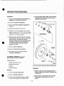
PEDAL REPLACEMENT (pin GT000200)
Tools Needed
• 5/8" Wrench
2. To install the left pedal, apply LOCT1TE® 242 to pedal threads, face the unit
and thread the pedal CCW into the crank.
With a 5/8" wrench, turn the nut CCW tightening securely.
• Solvent & Clean rag
• LOCTITE® 242
Removal
3. To install the right pedal, apply
1. To remove the left pedal, face pedal and
with a 5/8" wrench, remove it from the crank
by turning the pedal nut clockwise (CW).
LOCTITE® 242 to pedal threads, face the
unit and thread the pedal CW into the crank.
With a 5/8" wrench, turn the nut CW tightening securely.
2. To remove the right pedal, face the pedal
and with a 5/8" wrench, remove it from the
crank by turning the pedal nut counterclockwise (CCW).
SEAT REPLACEMENT
(pIn 3670M135)
Tools Needed
•
• 3/16" Hex key
Removal
1. Grasp the top ring of the bellows, squeeze
the front and rear together while pulling
down to free the bellows from the bottom of
the seat. If there are any Ty-Wraps securing
the bellows to the frame, they will need to be
cut before attempting to remove the bellows.
2. With a 3/16" Hex key, remove the four flat
head cap screws securing the seat.
Installation
1. Holding the replacement seat in position, reinstall the four flat head cap screws. See
Figure 5.5.
Figure 5.4 Pedal Replacement.
Note: Pedal nuts are stamped with an "L" for
LEFT and an "R" for RIGHT. Be sure to
reinstall them accordingly.
2. With a 3/16" Hex key, tighten the four
screws.
3. Lift the bellows to the seat bottom plate.
Align the three tabs to their holes in the bottom of the seat plate and press firmly
upward until the tabs click into place. Replace any Ty-Wraps that were removed in
Removal step 1.
Installation
•
1. Clean the threaded part of the pedal and the
threaded part of the crank with solvent. Inspect both parts to make sure the threads
are not distorted.
5-3
•
REPAIR PROCEDURES
FRICTION BELT ATTACHMENT CABLE
REPLACEMENT (pin 367JC212)
3. With a 7/64" Hex key, tighten the two
screws. Do not allow the cable lugs to turn
and kink the cable or to interfere with the
optical encoder drive belt.
Tools Required
4. Using the broad side of the flat blade screw-
• 7/64" Hex key
driver, gently bend cable end fittings
approximately tangent to surface of hub. See
Figure 5.9.
• Medium flat blade screw driver
Removal
5. If no other service is required perform
1. Perform Enclosure Removal.
Enclosure Installation.
2. Locate the Belt Attachment Cable screws
located at the top rear of the pendulum hub.
See Figure 5.9.
.0
Pendulum Hub
Assembly
Socket Head
Cap Screws
Clo~ed End
Of Ret.lner
Should Face Forward.
Cable End
Fitting
00004C
Figure 5. 10 Chain Replacement.
Cable Attaching Delail
CHAIN REPLACEMENT
000I1C
(pin 367GS260)
Figure 5.9 Belt Attachment Cable.
Tools Required
3. Slide the friction belt off of the flywheel and
• Phillips screwdriver
• Needle-nose pliers
remove the attachment spring from the
cable.
Removal
4. With a 7/64" Hex key. remove the two
screws securing the cable.
1. Perform Enclosure Removal.
Note: Note the routing of the chain before
removing it.
Installation
•
1. Install the replacement cable and the two
screws (install the screws only finger tight) .
2. Locate the master link of the chain.
3. Using needle-nose pliers, remove the mas-
2. Reattach the friction belt spring to the cable
and slide the belt into its groove.
ter link retainer. Remove the master link and
the chain.
5-7
•
REPAIR PROCEDURES
ROD PIVOT (pin 3670M545), SPRING (pin BS071367),
THREADED ROD (pin 3670M241) and
THRUST BUSHING (pin 367PE185)
REPLACEMENT.
4. Remove rod pivot and tension bracket as an
assembly.
5. Remove coupling. Unscrew the threaded rod
from the rod pivot and remove the compression spring.
Tools Required
6. Rotate rod pivot 90 0 to orient the tapped
hole away from the bracket opening. The rod
pivot should drop free. See Figure 5.13.
• 5/64" Hex key
• Wheel bearing grease
Removal
1. Perform Enclosure Removal.
2. With a 5/64" Hex key, loosen rear screw in
the flex coupling. Slide the coupling down
the threaded tension rod shaft.
•
Clip in Along Flat
3. Remove the grip rings from the pivot pins of
the tension arms. See Figure 5.12. Slide the
tension bracket off of the pivot pins.
Note: The grip rings deform easily, refrain from
spreading them too far apart. If they
should open too much, pinch them closed
with a plier or replace them.
Rotate 90 0
00116
Figure 5.13 Rod Pivot Alignment.
Installation
1. Position the rod pivot at the tension bracket
opening. Rotate the rod pivot so that it slips
into position and rotate it so that the tapped
hole aligns with hole in tension bracket. See
Figure 5.13.
Remove grip rings
from pivot pins (one
each side).
2. Apply a coating of automotive wheel bearing
grease to the bushing (flat) end. See Figure
5.14.
•
3. Install spring onto threaded rod. Clean old
grease from thrust washers and thrust bushing. Apply a new coat of wheel bearing
grease to both sides of thrust washers and
thrust bushing. See Figure 5.14.
Figure 5.12 Rod Pivot Pins.
5-9
•
REPAIR PROCEDURES
ENCODER REPLACEMENT (pin 3670K030)
Installation
1. Position the replacement board on the
mounting bracket and press into place
(board mounts one way only).
Tools Required
• .050" Hex key
• 5/16" wrench
2. Connect the wiring harness connector to the
sensor board. The connector can only be
plugged in one way.
• LOCTITE® 242
CAUTION Handle the wiring very gently.
3. Position the mounting bracket against the
left side flywheel support so that the screw
holes in the mounting bracket are aligned
with the screw key holes in the support
frame and the connector is toward the top.
Up
Removal
1. Perform Enclosure Removal.
2. With a .050" Hex key, loosen the set screw
in the encoder pulley. It may be necessary to
lift the pendulum to the rear so that the pulley rotates and the screw is accessible.
t\f
~
•
3. Slide the pulley toward the end of the shaft.
DO
own
Replacement Board
Orientation
4. With 5/16" wrench, loosen and remove the
retaining nut on the encoder.
.j / /
5. With the nut free, move the encoder toward
the hub until the encoder belt can be pulled
free of the pulley, then pull the encoder free
of the frame. Be sure to catch the pulley, retaining nut and flat washer.
6. Disconnect the encoder from the wiring
harness.
00117
Installation
Figure 5.16 Hall Effect Sensor Orientation.
1. Apply a small amount of LOCTITE® 242 to
threads on the retaining nut.
4. Install the two screws and toothed lockwashers through the frame (into the narrow
end of the key holes) and into the bracket.
Verify that wires are not pinched.
Note: Exercise extreme care when applying
LOCTITE to prevent it from entering
the encoder bearing.
5. With a Phillips screwdriver, tighten the
screws, do not over tighten.
•
6. Run the Tach Test as described in Section 4:
System Checkout.
7. If no other service is required perform
Enclosure Installation.
5-11
2. Position the replacement encoder at the
groove in the frame. Slide the flat washer
and retaining nut onto the encoder shaft.
Slide the pulley (set screw side away from
the encoder) onto the shaft while looping the
belt over it. See Figure 5.17.
•
REPAIR PROCEDURES
7. It no other service Is required perform
Enclosure Installation.
Hex Jam Nut
, ..
\
Flat Washer
Idler Lever Arm
(right side)
/
ENCODER BELT REPLACEMENT
(pin GB000367)
Pendulum Hub Axle
._0
ToolS Required
Encoder Belt
• 3/16" Hex key
Bearing
H"bs",re,~
• 2 - 9/16" Wrenches
• Plastic faced mallet
• Drift pin
• LOCTITE® 242
Removal
Pendulum Hub
Weldment
1. Perform Enclosure Removal.
Bearing
•
,-
2. Take a pen or pencil and mark the position
of the encoder belt on the pendulum hub.
Idler
Le or Arm
(left side)
With Cam
3. Perform Friction Belt Removal.
Idler Arm
Bushing
4. Perform Pendulum Hub Bearing Removal
(steps 3 through 5).
5. Utt the encoder belt off the pulley.
6. Using the 3/16" hex key, remove the socket
screw and washer from the pendulum hub to
release the belt.
\
Flat Washer - - l
Hex Jam Nut --.J
Installation
00013C
1. Install the replacement belt in the same position as the original. Replace the screw and
washer making sure the belt is aligned with
the mark made in removal step 2.
Rgure 5. 18 Pendulum Hub & {dler Lever Arm Bearing.
3. Loop the encoder belt over the encoder pulley. Position the axle in the frame and install
two flat washers.
2. Perform Pendulum Hub Bearing Installation (steps 1 through 5).
4. Apply a drop of LOCTITE® 242 on the pendulum hub axle threads and replace and
securely tighten the hex jam nuts with a pair
of 9/16" wrenches.
•
3. Run the Encoder Test as described in
Section 4: System Checkout.
4. Perform Friction Belt Installation.
5. If no other service is required perform
Enclosure Installation.
5. Perform Friction Belt Installation.
6. Run the Encoder Test as described in
Section 4: System Checkout.
5-13
•
REPAIR PROCEDURES
Installation
4. Using a plastic faced mallet, tap the bearing
cartridge out of the flywheel from the side
opposite the freewheel.
1. Perform Flywheel Bearing and Spacer Installation on replacement flywheel.
2. Perform Freewheel Installation.
Flat Washer
Short Flywheel Spacer (right)
3. Perform Hall Effect Magnet Installation if
required.
4. Install the flywheel into the frame.
5. Reinstall the two flat washers onto the axle.
Apply one drop of LOCTITE® 242 to the axle
threads. Reinstall the two hex nuts and. with
a pair of 3/4" wrenches, tighten.
Flywheel Bearing
Cartridge Assembly
6. Reposition the Hall Effect Sensor mounting
•
bracket against the frame with the connector
toward the top. Install the two screws
through the frame and into the bracket. With
a Phillips screwdriver, gently tighten the
mounting bracket screws. Do not over
tighten the screws.
7. Perform Chain Installation.
Hall Effect
~"""."
8. Perform Friction Belt Installation.
9. If no other service is required perform
Hex Nut
Long
Flywheel
Spacer (left)
Enclosure Installation.
FLYWHEEL BEARING (pin 3670K040)
and SPACER REPLACEMENT
Tools Required
Hall Effect~
Magnet
• Large adjustable wrench
00015B
• Plastic faced mallet
• Drift pin
Rgure 5.20 Flywheel Bearing & Spacer Replacement.
• LOCTITE® 242
Installation
Removal
•
1. Align the key in the new cartridge with the
keyway in flywheel and tap the cartridge fully
into flywheel.
1. Perform Enclosure Removal.
2. Perform Flywheel Removal.
2. Apply a drop of LOCTITE® 242 to threads
on cartridge. reassemble hex nut and
tighten.
3. Using a large adjustable wrench, remove
hex nut from flywheel. See Figure 5.20.
---------- -- ------------
5-15
------ -----
--
e
REPAIR PROCEDURES
CHAIN IDLER SPROCKET
REPLACEMENT (pin 3670M365)
2. Perform Pedal Removal.
3. Perform Chain Removal.
Tools Required
4. With an adjustable (or 1 114") wrench, remove
the lock nut located on the left crank leg by
turning the nut clockwise (CW). Slide nut off
the crank. See Figure 5.22.
• 9/16" Wrench
• LOCTITE® 242
Removal
5. Use the adjustable (or 11/4") wrench to remove the left bearing assembly by turning it
clockwise (CW). Pass the bearing assembly
over the left crank leg and remove.
1. Perform Enclosure Removal.
2. With a 9/16" wrench, remove the screw securing the chain idler sprocket.
See Figure 5.21.
6. Slide the loosened crank assembly out of the
crank housing.
Installation
7. Inspect and clean the bearing cups. If they
show wear and need to be replaced, tap
them out of the crank housing by using a flat
blade screwdriver and hammer.
1. Install idler sprocket screw through replace-
e
ment sprocket; apply LOCTITE® 242 to
screw threads and thread screw, with
sprocket. into lever arm.
2. With a 9/16" wrench, tighten the screw.
Check chain alignment.
3. Perform Enclosure Installation.
CRANK/SPROCKET (pIn 3670K045),
CRANK BEARING KIT (pIn 3670K360) and
BEARING CUP (pin FB030016) REPLACEMENT
Tools Requires
• Adjustable wrench or 1 1/4" wrench
• Flat blade screwdriver
• LOCTITE® 290
Bearing
Assembly Lock Nut
• Wheel bearing grease
Removal
00022C
1. Perform Enclosure Removal.
Figure 5.22 Crank with Sprocket and Crank Bearing.
e·
5-17
•
REPAIR PROCEDURES
2. Tilt the module forward and rest the mounting tabs in the main tube. While pressing
down on the Display Module to hold it
against the top of the tube, reinstall the four
Pan-L screws. Do not over tighten.
I
I
Power Output_
I,
Cable
r-
I . \
Power Supply...,
"
\
I
\
I
\
\
,
I
\
I \
Display
Module
Connector
\
\
Ground Lead - ,
3. Reinstall the power cord.
I
AC Power
Cable
I
\
-t--t--~7
7
TV-Wrap
/
rllifrtf rI ,----~
4. Refer to Section 4: System Checkout to perform Power Up Diagnostics and Field
Service Diagnostics.
,I.:
:;
If
I
L
,.
V
t
POWER SUPPLY REPLACEMENT
I ... , · ·
L- Hex Nuts
(pin EP470367)
:
'
Power Supply :
'
Cover,
:
i
L-0OO2OC
•
Figure 5.24 Power Supply Removal.
Tools Required
Installation
1. Position the replacement power supply in the
power supply cover. The P2 six pin connector should be oriented toward the top. Refer
to Figure 5.24. Secure the power supply to
the cover with four pan head screws.
• 5/16" Nut Driver
• Phillips Screwdriver
2. Position the power supply at the main tube
and connect the two plugs from the wiring
harness to the power supply board.
Connect as follows:
P2 of harness to J2 of power supply board.
P4 of harness to J1 of power supply board.
CAUTION: Always remove AC power from
The BIKE before attempting to service the Power Supply. The Power
Supply contains dangerously high
voltages.
3. Slide the power supply into the main tube.
The tabs along the bottom edge will hook
into the catches in the main tube. Slide the
top portion of the power supply cover over
the two studs.
Removal
1. Perform Display Module Removal.
2. With a 5/16" nut driver, remove the two hex
nuts securing the top of the power supply.
Remove the lockwasher and flat washer
from each stud. Remove tile ground lead
(P3). See Figure 5.24.
•
4. Install the ground lead (P3 of harness) onto
the left stud and fasten with a flat washer,
lockwasher and hex nut. Install a flat washer,
lockwasher and hex nut onto the second
stud. Witl' a 5/16" nut driver, tighten both
hex nuts.
3. Note the orientation of the power supply
board within the power supply cover. Remove the four pan head screws securing the
power supply to the cover. Remove power
supply from cover.
5. Perform Display Module Installation.
6. Refer to Section 4: System Checkout to perform Power Up Diagnostics and Field
service Diagnostics.
5-19
-------- -
-- --
---- ------ ---
•
REPAIR PROCEDURES
Installation
3. Perform Display Module Removal and
Power Supply Removal.
1. Reach inside the power entry module access
hole in the side of the base tube and retrieve
P9, P10 and P11.
4. Cut the Ty-Wraps that hold the harness to
the bike frame. There are two around the
crank housing and three on the left flywheel
support bracket.
2. Attach the connectors to the power entry
module as follows:
P9 of harness to L1 of module
P10 of harness to N1 of module
P11 of harness to GND of module
5. Perform Power Entry Module Removal.
6. Unscrew the ground lug near the front tube.
3. Position the power entry module as shown in
Figure 5.26 and snap back into place. Be
sure not to pinch the wires.
7. Disconnect the D.C. gear motor, pendulum
encoder and Hall Effect board.
8. Lift the power supply from the main tube and
disconnect the two connectors (P2 and P4)
from the main board.
4. Plug the power cord into the power entry
module and power outlet. Set the power
switch to the 1 (on) position. Ride The BIKE
to make sure it works properly.
•
9. The old harness is now free and the new
harness can be installed.
Note: The old harness will be used as a snake
to install the new harness.
CABLE HARNESS REPLACEMENT
(pIn 3670S377)
Note: When replacing the cable harness, the
power entry module (pin E5000367) must
also be replaced as it must be destructively removed to replace the cable
harness
Installation
Tools Required
1. Ty-Wrap the new harness, just behind the
25-pin D-eonnector, to the part of the old
harness hanging out of the 3-inch access
hole in the 4 x 6 tube.
2. From the top of the 4 x 6 tube, pull out the
old harness until the D connector of the new
harness hangs out of the tube about 12
inches. Cut the Ty-Wrap and discard the old
harness.
• Utility blade
• Hammer
• Flat blade screwdriver
• Ty-Wraps
3. Reach inside the power entry module access
hole. in the side of the base tube. and retrieve plugs P9, P10 and P11.
Removal
1. Turn the power to the unit to the 0 (off) position and remove the power cord from the
power outlet and the power module.
The new harness is now installed. Reconnect and install all components and
connectors removed in steps 1 through 7.
Refer to Figure 5.27.
2. Perform Enclosure Removal.
•
5-21
•
SECTION
WARRANTY AND SERVICE POLICY
THE CYBEX SERVICE POLICY
CYBEX Customer Service. When appropriate,
Customer Service will provide a special re-usable
crate for the shipment of certain major components. These crates are shipped and invoiced, then
credited in full on return.
This statement of Service Policy is not a warranty
and in no way alters the terms, conditions or
requirements of the warranty. The Service Policy
represents only our current procedures for handling service requirements during and after the
warranty period. Although we do not have sales
and service representatives in every location, we
can and will provide excellent warranty and continued maintenance service. Please call CYBEX
Customer Service if you have any questions.
3. Repair Polley
A Return Authorization Number is required on any
return for repair or credit. For non-warranty repairs, a written purchase order is required to cover
material, labor and shipping costs. Repairs paid for
by customers are warranted for 90 days from date
of repair. Subsequent parts failure unrelated to the
repair are not warranted and therefore chargeable.
1. Shipping Cost Policy
•
If a service requirement arises during the first year
of use for any CYBEX product which requires the
return for repair or replacement of that product or
any of its components, parts or accessories, it is the
current policy of CYBEX to pay directly or reimburse our customer for all shipping costs
connected with the repair or replacement in excess
of five dollars ($5.00). The only requirements for
obtaining' this extra service are that a Return
Authorization Number be obtained from the
CYBEX Customer Service Department and that
any return shipments are made only by the method
or carrier instructed by Customer Service.
4. Response Time Polley
It is the policy of CYBEX to respond to customer requests for technical service by dispatching service
personnel and/or by shipping necessary components, parts or accessories normally within two
business days in major metro areas and four days
in rural areas from date of request.
5. Standard Service Rates
For service rates for out-of-warranty repairs. consult the Services Price List.
Minimum Service charge is the minimum one-hour
charge plus appropriate zone charge.
This policy does not include total cost of air freight
shipments requested by the customer. These will
be paid or reimbursed on a pro-rated basis (difference between motor and air freight cost is the
responsibility of the customer). This also does not
include shipment outside of North America.
Standard Warranties
Every CYBEX product is warranted against defects
in materials and workmanship. Warranty periods
vary among products.
2. Return and Replacement Policy
If a need for service arises during the first year of
use of any CYBEX product which requires the replacement of a defective component, part or
accessory, it is the current policy of CYBEX to expedite service by immediately shipping - and
invoicing for the appropriate replacement. This invoice is then credited in full on receipt of the
authorized return by CYBEX. Invoicing and return
for credit may be waived in some cases when cost
of handling exceeds value of item.
•
6
It is the policy of CYBEX to provide (with no
charges for parts, labor or transportation) appropriate warranty repair or replacement of any defective
component, part or accessory within ten business
days from the date a problem is reported.
6. Standard Business Hours:
Inside Telephone Technical Support is available
from Monday- Friday 8 a.m. -6 p.m. Eastern Time
Zone toll-free at 1-800-892-2732.
To obtain credit, any returned component, part or
accessory must be packed carefully to avoid damage in transit and must be clearly marked with
Return Authorization Number obtained from
On-Site Technical Service is available from Monday through Friday 8 a.m. - 5 p.m. in your
respective time zone.
6-1
•
WARRANTY AND SERVICE POLICY
This warranty gives the purchaser specific legal
rights, and the purchaser may also have other
rights depending on state law..
warranty Disclaimers and Additional
Information
There are no additional warranties, either expressed or implied, arising out of the sale of this
product other than those contained herein except
an implied warranty of fitness for the purpose intended for a period of two years or as noted below.
This warranty extends only to the repair or replacement of the product and does not afford additional
coverage with respect to any incidental or consequential damages arising from the use or non-use
of this product. CYBEX is not responsible for any
lost data or interrupted system operation.
•
The warranties contained herein are expressly in
lieu of any other warranties, including implied warranty of merchant ability and/or fitness for purpose.
During this warranty period (one year), the product
will be either repaired or replaced (at POLAR's option) without charge in the country where it was
originally purchased.
For repair or replacement of your POLARTM HRM,
in the USA, there is a $7.50 US charge for handling
through POLAR.
Systems that are used in mobile environments, or
that are relocated by other than CYBEX carriers
and technicians, require special warranty and service coverage which is available at extra cost
depending on individual circumstances. Warranty
is voided if system is moved from place of original
installation without approval of the CYBEX Customer Service Department.
SERVICE
To insure proper service of your POLARTM HRM
please fill out and mail the enclosed warranty registration card within 14 days after purchase.
• Carefully pack the POLARTM HRM transmitter and wrist receiver in a shipping carton so
it will not be damaged.
Some states do not allo ti,e exclusion or limitation
of incidental or consequential damages and/or limitation on how long an implied warranty lasts, so the
above limitations or exclusions may not apply to
you.
• Enclose proof of purchase (or photocopy).
Please include a statement explaining why
the unit is being returned for repair.
This warranty gives you specific legal rights and
you may also have other rights which may vary
from state to state.
• Mail postage prepaid to:
POLAR WARRANTY:
• Remember to include a check or money ~
order for the $7.50 handling, return postage
and insurance charge (this is not a repair
charge).
POLAR CIC, Inc.
gg Seaview Boulevard
Port Washington, NY 11050
Transmitter, Belt and Watch
POLAR warrants to the original consumer/purchaser that the transmitter and the watch will be
free from defects in material or workmanship for
one year from date of purchase. Warranty does not
cover damages due to misuse, abuse, or accidents, negligence of \t,e precautions; improper
maintenance or commercial use; cracked or broken cases. Warranty is voided if repairs are made
by persons no a thorized by POLAR.
•
TECHNICAL DATA
• Estimated average battery life: 2500 hours of
use when handled according to the care and
maintenance instruction.
• Battery Type: CR 2025
Battery Replacement:
Transmitter: replace transmitter
Wrist receiver: only by those persons authorized by POLAR, or at a qualified watch store.
To assure proper registration of your POLARTr.!
HRM, in USA, please mail warranty registration
card within 14 days after purchase using the enclosed warranty card.
• Water resistant 20m.
6-3
•
SECTION
EXPLODED VIEW DRAWING AND PARTS LIST
PART ORDERING INFORMATION
We realize that whenever a replacement part is ordered, receiving the correct part in a timely fashion
is extremely important.
As a result, the following information will greatly enhance our service to you. Please have this
information ready when calling:
1. The unit SERIAL NUMBER.
2. The unit NAME.
3. The PART DESCRIPTION and the PART
NUMBER.
•
Identify the part needing replacement in the
exploded view drawing on the following
pages. Using the item number on the drawing, locate the item number on the Parts Ust
to obtain the part description and part number.
4. The FACILITY NAME, ADDRESS and
CONTACT NAME.
(Your CUSTOMER NUMBER is helpful, but
not necessary.)
In addition to the replacement parts listed on the
following pages, POLART:-l Heart Rate Monitor
transmitters can be purchased. Their part numbers
are as follows: .
Description
•
CYBEX
Part No.
Transmitter and belt
3670HRTB
Belt only
3670HRB
POLARTM Favor
(Transmitter, belt & watch)
3670HRF
To order parts, or for assistance, contact CYBEX
Customer Service at 1-800-892-2732, in New
York State call 516-585-9000.
7-1
7
•
A
APPENDIX
TOOL LISTING
List of tools required for service procedures featured in this publication. The tools contained in this list do
not coincide with the order of their appearance in this publication.
•
•
Qty.
No.
Description
1.
2.
3.
4.
5.
6.
7.
8.
9.
10.
11.
12.
13.
14.
15.
16.
17.
18.
19.
20.
21.
22.
23.
24.
25.
26.
27.
28.
29.
30.
31.
32.
Phillips Screwdriver
'. . . . . . . . . . . . .. 1
Small Phillips Screwdriver. . . . . . . . . . . . . . . . . . . . . . . . . . . . . . . . . . . . . .. 1
Flat Blade Screwdriver
1
Large Flat Blade Screwdriver
. . . . . . . . . . . . . . . . . . . . . . . . . . . . . . .. 1
Adjustable Wrench
'
'1
Large Adjustable Wrench
1
Needle Nose Pliers
. . . . . . . . . . . . . . . . . . . . . . . . .. 1
Vise Grip or ChanneHock Pliers
1
Fine Grit Sand paper. . . . . . . . . . . . . . . . . . . . . . . . . . . . . . . . . . . . . . . . . .. 1
.050" Hex Key
1
5/64" Hex Key . . . . . . . . . . . . . . . . . . . . . . . . . . . . . . . . . . . . . . . . . . . . . . .. 1
7/64" Hex Key . . . . . . . . . . . . . . . . . . . . . . . . . . . . . . . . . . . . . . . . . . . . . . .. 1
3/32" Hex Key
1
1/8" Hex Key
1
5/32" Hex Key . . . . . . . . . . . . . . . . . . . . . . . . . . . . . . . . . . . . . . . . . . . . . . .. 1
3/16" Hex Key . . . . . . . . . . . . . . . . . . . . . . . . . . . . . . . . . . . . . . . . . . . . . . .. 1
1/4" Hex Key
1
5/16" Open End Wrench . . . . . . . . . . . . . . . . . . . . . . . . . . . . . . . . . . . . . . .. 1
9/16" Open End Wrench
2
5/8" Open End Wrench .. . . . . . . . . . . . . . . . . . . . . . . . . . . . . . . . . . . . . . .. 1
3/4" Open End Wrench
2
1/4" Nut Driver
' . . . . . . . . . . . . . . . . . . . . . . . . . . . . . . . . . . . . . .. 1
5/16" Nut Drj er
1
Drift Pin
1
Plastic Faced Mallet
:.................. 1
Hammer
1
Utility Blade . . . . . . . . . . . . . . . . . . . . . . . . . . . . . . . . . . . . . . . . . . . . . . . . .. 1
'
air
Teflon Based Grease
Wheel Bearing Grease
air
LOCTITE® 222
air
LOCTITE® 242
air
LOCTITE® 490
air
Note: In case of accidental spillage of LOCTlTE®, soak up with an inert absorbent. Store in a partly filled,
closed container until disposal. Check with local and EPA regulations for proper disposal method.
In case of skin contact, wash affected area thoroughly with soap and water. In case of eye contact,
flush eye at least 15 minutes with water and obtain medical attention.
A-1
•
INDEX
Beep Test, 4-9
Bellows, replacement, 5-5
checking, 4-8
replacement, 5-11
Encoder Test, 4-7, 5-13. 5-22
Belt. See Friction Beft
Belt Tensioning Mechanism, 3-1, 3-5
checking, 4-7
Field Service Diagnostics, 4-6
Cable Harness, 3-1, '3-9
replacement, 5-21
Flywheel, 3-1,3-4,5-5,5-13
cleaning instructions, 2-1
replacement, 5-14
Calibration, 4-10
Flywheel Bearing, replacement, 5-15
Caster
eccentric, 1-1
lubrication, 2-3
Freewheel, 3-1, 3-4
replacement, 5-16
Flex Coupling, 5-8
Chain, replacement, 5-7
Chain Idler Mount, lubrication, 2-3
Chain Idler Sprocket, replacement, 5-17
•
Crank, 3-1, 3-4
housing, 5-18
replacement,5-17
Fuse, replacement, 5-20
Grounding, 1-2
Customer Service, 7-1
D.c.
Motor, 3-1, 3-5
checking, 4-7
replacement, 5-8
Hall Effect Boa;d, 3-1,3-4
Hall Effect Magnet, 3-4
replacement, 5-14
Hall Effect Sensor Board. 5-10
Daisy-Chain, 1-2,3-8
Handlebar, replacement, 5-2
Detent Pin
lubrication, 2-3
replacement, 5-5
Hand Grip, replacement, 5-2
Diagnostics
field service, 4-6
power up, 4-1
Display Module, 3-1
replacement, 5-18
Enclosure
removal, 5-1
replacement, 5-1
•
Friction Belt, 4-3
attachment cable, 5-7
replacement. 5-5
Encoder
belt, 5-13
Heart Rate Monitor, 1-1,3-6,4-3
part numbers, 7-1
Idler Lever Arm
bearing lubrication, 2-3
bushing replacement, 5-12
tension bracket pivot lubrication, 2-3
Initial State, 1-3
Keypad,3-7
Keypad Test, 4-8
~-----------------------------------------------------------
:RIPTlON
E
ENT. CYCLE FRAME ('NHITE)
ENT. CYCLE FRAME (BlACK)
NT. HAI'DlEBAA (WHITE)
IDMENT. HAI'DlEBAA (BlACK)
DMENT. SEAT P05T
:KET. MOTOR MOUNTlNG
OMENT. PENDULUM BlOCK
OMENT. PENDULUM DRUM
:J<. FOAM (PENDULUM)
OMENT.CAM
~ PEf'DULUM HUB
I-FflJCTION TAPE. 1.25 WIDE
WASHER
:ER. HUB
)MENT. IDLER LEVER ARM (l)
)MENT. IDLER LEVER ARM (R)
)MENT. TENSION BRACKET
MEEL
ER. FLYWHEEL (LONG)
ER. FLYWHEEL (SHORT)
PIVOT
ADEDROD
INING RING
AY MODULES (WHITE)
1ESTICISTANDARD
MAN
'!ISH
USHMETRIC
KH
IAN
_
3670ClOO
367OCIOO·1
367OCl25
367OC12S-1
3670PI37
3670CII0
3670C215
3670C202
3670MI14
3670C265
3670M220
YDOOOO36
HS347603
3670P221
3670C238
3670C240
3670C225
3670M201
3670P507
3670P506
3670MS45
3670M24I
BR030367
36705399
36705399-D
3670S399-E
36705399-ElM
3670S399-F
3670S399-1
NESE
3670S399~
DISH
3670S399·S
'Y MODULE5 (BlACK)
.~ClSTANDARD
~ISH
USHMETRIC
ICH
AN
NESE
)ISH
;SY. HAlL EFFECT
DER.
128 UNE
ESS
'RJCTION
10LDED
,SEAT POST RETENTION
IAf'DLEBAA
TINT
;, COMPRESSION.
NOB. 1.375 DIA
SEAT POST SCAlE
~
POWER 5UPPlY
'SURE ASSY. RIGHT SIDE (WHITE)
OSURE ASSY. RIGHT SIDE (BlACK)
'SURE ASSY, LEFT SIDE (WHITE)
OSURE ASSY. LEFT SIDE (BlACK)
~ CONCENTRIC
~ECCENmiC
fBUSHING
BELLOWS A ITACHMENT
\IS
:T. MOUNTING (MOLDED)
T,R.YWHEEL
:ET. 60 TEETH
-uT718-24
•
PART No.
~ PEDAl WISTRAP
,5UPPlY. 90 - 265 VAC
LOGO
ENTRY MODUlE
36705399-1
3670S399-ID
36705399-IE
36705399-1 ElM
36705399-1 F
36705399-11
3670S399-1)
36705399-IS
36705310
ECOOO367
36705377
36705601
.. 3'670M-i 35
367JCI40
367PPl29
, 3670PISI
85070205
-PP460200
367CM145
3670 190
367PEI94
367PE194-1
367PEI95
367PEI95-1
367WC188
367WC189
367PEI85
367PEI86
367PRI87
367PPl97
EV420003
3610M260
3610P264
GTOOO200
EP470367
367CM299
85070367
ESOOO367
I
64
@
•
so
•
~670K360
, - - - - - - ---
•
----@
•
•
No.
6S
66
67
69
70
71
72
73
74
7S
76
77
78
79
80
82
84
8S
86
87
88
89
90
91
92
94
95
96
•
97
100
101
102
105
106
108
III
112
114
115
116
118
124
125
126
127
128
131
132
133
134
140
144
14S
146
147
148
149
ISO
•
IS9
162
171
172
178
DESCRIPTION
PART No.
BUSHNG, SNAP. I.S DtA
BUSHING, SNAP, 3.0 DtA
De MOTOR
FASTENER, TlNNERMAN, 8-32 J-TYPE
TIMING BELT. ENCODER
PUlLEY. TIMING BELT (ENCODER)
CHAIN. DRIVE. 98 UNK
IDLER ARM BUSHING
SPRING, COMPRESSION
CABlE. BELT ATIACHMENT
GEAAGRIP R.EX.IBLE COUPLING
NVT. 112-20 UNF-3B SELF LOC HEX.
FLAT WASHER, 112
HEX JAM NVT. 3/8-24
WASHER. .383 ID x 1.2S OD x .03
HEX. HD CAP SCREW, 112-20 x I
SOCKET HD CAP SCREW, 6-32 x 3/8
SOCKET LO HD CAP SCREW. 10-24 x 3/8
SOC HD CAP SCREW. 10-32 x 3/4
LO HD SOC CAP SCREW. 10-24 x 1/4
FL HD SOCKET SCREW, S/16-18 )( 3/4
FUSE. 1 AMP @ 250V
HEX NVT, 6-32 KEPS
SCREW. THREAD FORMING. #6 x 112
SCREW, HEX. SlOT. 8-32 x 112
PAN-L SCREW. 8-32 x 9/16 (GRAY)
PAN-L SCREW. 8-32 x 9/16 (WHITE)
PAN-L SCREW. 1/4-20 x S/8 (GRAY)
PAN-L SCREW. 114 - 20 X 3/4 (WHIT£)
PAN-L SCREW. 1/4 - 20 X 3/4 (BlACK)
SOCKET HD CAP SCREW, 4-40 x 1/4
ENCODER WASHER
SHOCK MOUNT, MOTOR MOUNTING BRACKET
RADIAL BALL BEARING (PENDULUM)
EXTERNAL GRIP RING
LOCKWASHER, #6 EXTERNAL TOOTH
PH PAN HD SCREW, 8-32 x 5/16
FLAT WASHER, #10
LOCK WASHER. #10
#6 x 1/4 PH PAN HD SCREW WIlWASHER
PUSH MNT CABLE TIE ANCHOR, 1/4
CABlE TIES S/8 - 3/4 DlA
lABEL UL WARNING
WELDMENT. CHNN IDLER ARM
TORSION SPRlNG
CHAIN IDLER MOUNT
FLAT WASHER, 1 OD x .15 ID x .04S
SPROCKET. IDLER
FLAT HD SOCKET SCREW, 114-20 x I
HEX HD CAP SCREW. 3/8- 16)( 1/4
SHOULDER SCREW, # 10-32 x 3/1 6
WASHER
lABEL "THE BIKE'
lABEL 'THE BIKE'
SOCKET LOW HD SCREW # 10-24 x 3/8
OJSHION. SEAT POST
RUBBER BUMPER
HEX HEAD SCREW, 1/4-20 x I
SCREW CAP WASHER
SCREW CAP (WHIT£)
SCREW CAP (BlACK)
SHIM. HANDlE BAR
FLAT WASHER
RETAINER
KEY
NVT
VOLTAGE RATING lABEL
FLY\AJHEEL BEARING ASSEMBlY
B1KE1SEMI CRANK REPlACEMENT KIT
WHITE TOUCH-UP PAINT
BlACK TOUCH-UP PAINT
8.410007
EL410008
367EM250
HF08000S
GBOOO367
GPOOO367
367GS260
3670PIS2
BS071367
367JC212
FC I00367
HN7944OOCO
HS760IOI
HN714400
HS347602
H081217
HCS32810
HCS728 I I
HCS72815
HC583408
HC6610lS
m900IO
HNS34300
H\o\I062S 12
HMS41712
HM541813
HMS41813-1
HMS41813
HM6218t4
HM6218IS-;:
HCS22808
HS307603
PP260367
~
AlO4OOO4
BRD300S3
HS068300
HMS42609
HS107607
HS108300
HMS32S08
PC 149628
EWOOOOl3
367CM297
3670060
BS072367
3670P364
HS067602
3670M365
HM620914
HOOlllO
HD303306
HS107601
367CM295
367CM29S-1
HCS728 I 1
367OMI43
PRD60367
HC621217
HSO 1000 I
PP080007
PP08000S
3670MI30
HS087601
3670MSI7
3670MSII
3670PSI2
367CM293
3670KlOI
3670K360
KT090008
KT050002
<