1
ZENITH
SERIES
INSTRUCTIONS FOR USE
SERVICE MANUAL
To avoid personal injury or damage to bed,
please read all sections pertaining to
the bed model before use.
ETL/UL/CSA APPROVED
UL 60601-1
IEC 60601-2-38
CSA 22.2 601.1
GF Health Products, Inc. - www.grahamfield.com
Zenith Series Service Manual 999-0831-190C DEC. 2013
This service manual covers the following Zenith APS Models:
76” & 80” Full Electric with Pedal Lock Caster System & Grid Decks = APS98174;
76” & 80” Full Electric with Pedal Lock Caster System, Grid Decks, and Underbed Light = APS981741;
76” & 80” Full Electric with Pedal Lock Caster System, Grid Decks, Underbed Light,
and Onboard Battery Backup System = APS981742;
Basic American Medical Products
336 Trowbridge Drive
Fond du Lac, WI 54937
For Zenith 9000 Bed Service Parts
please contact our Customer Service Department
at 1-800-365-2338
GF Health Products, Inc.
2935 Northeast Parkway
Atlanta, GA 30360
www.grahamfield.com
To order a Zenith 9000 Bed
please contact a Graham Field Sales Representative
at 1-800-554-9215
IMPORTANT NOTICE
GF Health Products, Inc. is not responsible for typographical errors.
All illustrations, specifications, packaging, and warranties contained in this Service Manual
are based on the latest product information available at the time of printing.
The most current product information can be found online at www.grahamfield.com.
Please check all parts for shipping damage and test before using.
In case of damage, DO NOT USE.
ZENITH SERIES
TABLE OF CONTENTS
IMPORTANT INFORMATION REGARDING YOUR BED
Safety & Warnings . . . . . . . . . . . . . . . . . . . . . . . . . . . . . . . . 4 - 5
Entrapment/Compliance . . . . . . . . . . . . . . . . . . . . . . . . . . . . . . . 5
Recommended Maintenance . . . . . . . . . . . . . . . . . . . . . . . . . . .6
Warning Labels and Environmental Specifications . . . . . . . . . . 7
SECTION A - BED SET-UP . . . . . . . . . . . . . . . . . . . . . . . . . . . . . . . . . . 8
Unpacking Your Bed . . . . . . . . . . . . . . . . . . . . . . . . . . . . . . . . . .9
Headboard and Footboard Installation . . . . . . . . . . . . . . . . . . .10
Standard Mattress Retainer Installation . . . . . . . . . . . . . . . . . .11
Standard Wallsaver Installation . . . . . . . . . . . . . . . . . . . . . . . . .12
Optional Trendelenberg Wallsaver Brackets . . . . . . . . . . . . . . .13
Plugging in Your Staff/Nurse Control . . . . . . . . . . . . . . . . . . . . .14
Pendant/Hand Controller Operation . . . . . . . . . . . . . . . . . . . . .15
Staff/Nurse Control Operation . . . . . . . . . . . . . . . . . . . . . . . . . .16
Bed Operations - Chair Position . . . . . . . . . . . . . . . . . . . . . . . .17
Bed Operations - Trendelenberg/Reverse Trendelenberg . . . .18
SECTION B - ASSIST DEVICES . . . . . . . . . . . . . . . . . . . . . . . . . . . . . 19
Optional Pivoting Assist Bar Installation . . . . . . . . . . . . . . . . . . 20
Optional Half Rail Installation . . . . . . . . . . . . . . . . . . . . . . . . . . 21
Optional Trapeze Support Installation . . . . . . . . . . . . . . . . . . . 22
SECTION C - MECHANICAL/ELECTRICAL INFORMATION . . . . . . . 23
SECTION D - SERVICE/REPLACEMENT PARTS . . . . . . . . . . . . . . . . 29
SECTION E - TROUBLESHOOTING . . . . . . . . . . . . . . . . . . . . . . . . . . 38
WARRANTY INFORMATION . . . . . . . . . . . . . . . . . . . . . . . . . . . . . . . . .43
LABEL SYMBOL DEFINITIONS
!
!
Consult
Accompanying
Documents
Safe
Working
Load
GF Health Products, Inc. - www.grahamfield.com
Double
Insulated
Protected
Grounded
Device
Type B
Equipment &
Applied Parts
3
Zenith Series Service Manual 999-0831-190C DEC. 2013
ZENITH SERIES
IMPORTANT SAFETY AND WARNING INFORMATION
!
This product is a variable height, adjustable mattress
platform, which will provide comfort and convenience
for residents/patients and caregivers in long term
care settings.
!
The MAXIMUM SAFE WORKING LOAD for the
APS 9000 Bed with weight evenly distributed, including
bedding, resident/patient, support surface, and all
accessories, is 600 lbs.
!
NEVER operate the bed if a Power Cord or Plug is
damaged or not working properly. Contact qualified
Service Personnel for examination and repair. Always
unplug the Power Cord when performing any maintenance on the bed.
!
Beds manufactured by Basic American Medical Products
are designed for use within an institutional healthcare
environment (i.e. assisted living, skilled nursing, transitional care, rehabilitational care, etc.).
!
DO NOT use the assist devices as push handles for moving
the bed. Assist devices can be deformed or broken if
excessive side pressure is exerted. Assist devices are not
meant for patients considered as high risks for entrapment
(i.e. patients with pre-existing conditions such as
confusion, restlessness, lack of muscle control, altered
mental status, either organic or medicinal, or a combination thereof). Additional safety measures should be
considered for such high-risk patients.
!
NEVER permit more than one (1) person on/in the bed
at any time.
!
Body weight should be evenly distributed over the
sleeping surface of the bed. DO NOT allow the patient
to lay, sit, or lean in such a way that their entire body
weight is placed only on the raised head or foot sections
of the bed. This especially applies when repositioning
or transferring a patient in or out of the bed. Increased
risk may occur when the patient’s size and/or weight are
inappropriate for the bed’s dimensions or weight capacity.
!
DO NOT open assemblies such as the Actuators, Hand
Control, or Control Box. If unauthorized personnel
perform work on these components, the manufacturer’s
warranty becomes void.
!
DO NOT use unauthorized parts, accessories, or
adaptors other than those specified/authorized by
GF Health Products, Inc.
!
When operating the HI/LO, Knee, or Back Functions
of the bed, ALWAYS ensure that the confined individual
is positioned properly within the confines of the bed.
DO NOT let any extremities protrude over the side or
between the bed rails when performing these functions.
!
Risk of entanglement or injury may occur if the mattress
used with mattress retainers does not fill the entire width
between stops or which compresses to less than 1.50
inches under user’s weight.
!
DO NOT lower the bed when objects are beneath it.
Failure to inspect under the bed can result in damage
to property or personal injury.
!
!
The bed’s Pendant Cord MUST BE ROUTED AND
SECURED PROPERLY to ensure it does not become
entangled and eventually severed during use. Also
make sure all electrical cords DO NOT get tangled
around the bed, side rails, or legs during transport or
normal operation of the bed.
Mattress must be properly sized to fit the mattress support
platform and must remain centered on the support platform
relative to State and Federal guidelines. Recommended
minimum dimensions of mattress is 35 inches wide and
6 inches deep. Length should match the mattress support
platform. Use of an improperly fitted mattress could
result in injury or death.
!
IMPORTANT: Powered air mattress surfaces may pose
a risk of entrapment. Prior to use, ensure the therapeutic
benefits outweigh the risk of entrapment.
!
The bed is intended for use, storage, and transport within
a temperature range of -40˚C to +60˚C. It has a waterresistance rating of IPX6 and IS NOT to be powerwashed or submersed.
!
When using nasal-type or masked-type administering
equipment, all oxygen or air tubing MUST BE ROUTED
AND SECURED PROPERLY to ensure that the tubing
does not become entangled and eventually severed
during the normal operation of the bed.
!
Keep all moving parts free of obstructions (i.e. blankets/
sheets, heating blankets/pads, wiring, etc.).
GF Health Products, Inc. - www.grahamfield.com
4
Zenith Series Service Manual 999-0831-190C DEC. 2013
ZENITH SERIES
IMPORTANT SAFETY AND WARNING INFORMATION
!
!
The head/back and knee/foot decks can be lifted freely
by hand for easy cleaning access when patients are not
in the bed. If you lift the head/back or knee/foot deck
for any reason, please take great care when lowering
back down to the prone position - make sure that all
body parts are clear of the space between the deck and
the bed prior to slowly lowering any deck manually. To
avoid injury, DO NOT LET DECKS FALL FREELY
FROM ANY ANGLE.
Notice for California Customers California Proposition 65 WARNING: This product
contains a chemical known to the State of California to
cause cancer and reproductive or developmental harm.
!
Proper routing and tie-off of electrical cabling, especially
the power cord, is essential for proper operation and to
ensure safety from electrical shock. In the event you are
replacing any electrical cabling on your bed, you must
make sure the cables are free from any pinch points,
obstructions, or stretched so tight that they may come
loose or become damaged. In addition, cables should
be tied off in such a way to secure them and keep them
free from tangling on any part of the bed during normal
operation. Refer to your service manual’s electrical
section for proper cable routing.
ENTRAPMENT & COMPLIANCE INFORMATION
On April 10, 2006, the FDA (U.S. Food and Drug Administration) released long-awaited guidelines for reducing the risk
of bed entrapment: “Hospital Bed System Dimensional and
Assessment Guidance to Reduce Entrapment”. The new Guidance
identifies potential entrapment areas and those body parts most
at risk for entrapment; provides design criteria for manufacturers
of new hospital/convalescent beds; recommends particular test
methods to assess the conformance of existing hospital/convalescent bed systems; and answers frequently-asked questions
about entrapment issues.
The new Guidance was a result of a long-standing collaboration
between the FDA and the Hospital Bed Safety Workgroup
(HBSW), formed in 1999. GF Health Products, Inc’s LongTerm Care Bed division: Basic American Medical Products, is
an HBSW charter member. As a result of our commitment to
product safety, all our current long-term care beds have been
strictly tested and conform to the new FDA Guidance.
The guidelines set forth by the FDA Guidance layout specific
dimensional limitations on potentially injury-threatening gaps
and spaces that can occur between bed system components,
such as rails, when not properly installed. GF Health Products,
Inc. and Basic American Medical Products have conformed
to these guidelines from a manufacturing aspect. However,
entrapment issues can often arise when a healthcare provider/
facility has not correctly assembled the components on a bed.
It is essential that the provider/facility fully understand their
GF Health Products, Inc. - www.grahamfield.com
responsibility in complying to the guidelines set forth by the
FDA in order to avoid injury. To that end, we have provided
the FDA’s web address at right as a resource for understanding
and following these guidelines for the safety of patients/residents.
It is also essential to have the correct bed components/accessories that correspond with the needs of the patient/resident
and the particular bed you have purchased. Matching the correct
bed component that correlates with the regulatory guidelines can
be a daunting task. Our sales team at GF Health Products, Inc.
and our friendly Customer Service Representatives at Basic
American Medical Products can help you sift through the wide
array of compliance and bed options. We will help you determine
which bed/bed part is best for the patient’s/resident’s particular
needs and help you with any compliance issues.
The Zenith APS 9000 bed and accessories listed in this
manual are in full compliance with FDA guidelines
for reducing the risk of bed entrapment: “Hospital
Bed System Dimensional and Assessment Guidance
to Reduce Entrapment”.
Details can be found at www.fda.gov.
5
Zenith Series Service Manual 999-0831-190C DEC. 2013
ZENITH SERIES
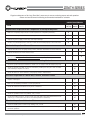
Regular maintenance of the Long Term Bed is necessary to ensure continuing proper and safe operation.
Please read and observe the following recommended maintenance schedule.
RECOMMENDED
INSPECTION PERIODS
Inspect
Every
on Receipt 3 Months
ITEM
Every
6 Months
Maintenance Inspection of All Components at Receipt of Shipment
Make sure all parts/components are included (Please see “Unpacking The Bed”).
X
Check all bed components for obvious damage.
X
Inspect the power supply cord for any cuts and/or damage.
X
Check to see all actuator/motor cords are routed and connected properly to the control box.
X
Mechanical Inspection of Assemblies
Inspect all welds on the sleeping surface, frame, and base assemblies for stress fractures.
X
Inspect all fasteners for wear and looseness.
X
IMPORTANT: Lubricate all pivot points, actuator/motor clevis pins, and control arm clevis
pins as needed. White Lithium Grease is recommended.
X
Mechanical Inspection of Casters & Pedal Locking Mechanism
Check the pedal locking mechanism to make sure it engages and disengages properly.
X
Check the bottom foot pads on the foot end casters, making sure they are clean of debris
and undamaged. Replace if needed.
X
Check all casters to ensure that they roll properly and are unobstructed.
X
Electrical Inspection of Control Box, Pendant, and Staff Control
Check the external power cord that plugs into the control box for any chafing, cuts, or wear.
Replace if damaged.
X
Make sure all attaching hardware is securely tightened.
X
Check all electrical connections for any wear or fractures.
X
Check the external backup battery (if you have one). Replace if needed.
X
Check the pendant cord for any chafing, cuts, or wear.
X
Check all pendant functions - check to make sure each button and associated function work
properly (i.e. head section rises when the Head Up button is activated).
X
Electrical Inspection of Actuators/Motors
Check the actuator/motor cords for any chafing, cuts, or wear.
X
Check the range of movement on all motors to ensure they do not bind in the Full Up or
Full Down positions.
X
GF Health Products, Inc. - www.grahamfield.com
6
Zenith Series Service Manual 999-0831-190C DEC. 2013
ZENITH SERIES
The following warning labels have been placed on the bed to help protect you and the bed from damage.
Please do not remove any labels from the bed.
WARNING!
CAUTION
DO NOT LOWER BED WHEN OBJECTS ARE
BENEATH BED. FAILURE TO INSPECT UNDER
BED CAN RESULT IN DAMAGE TO PROPERTY
OR PERSONAL INJURY.
ATTENTION:
S’assurer de ne pas faire descendre le lit
lorsque des objets se trouvent sous le lit. Ne
pas inspecter le dessous du lit pourrait entrainer
des dommages materiels et des risques de
blessures.
THIS BED IS SUITABLE FOR USE ONLY WITH
OXYGEN ADMINISTERING EQUIPMENT OF
THE NASAL OR MASK TYPE OR A TENT
COVERING ONLY THE UPPER HALF (HEAD
END) OF THE BED. OXYGEN TENT CANOPIES
SHOULD NOT EXTEND BELOW BED SPRING
LEVEL. LOCK HAND CONTROL AT FOOT OF
BED WHEN USING OXYGEN ADMINISTERING
EQUIPMENT.
ATTENTION:
WARNING!
DO NOT LOWER BED WHEN
OBJECTS ARE BENEATH BED.
FAILURE TO INSPECT UNDER
BED CAN RESULT IN DAMAGE
TO PROPERTY OR PERSONAL
INJURY.
CE LIT PEUT ETRE UTILISE UNIQUEMENT
AVEC UN EQUIPMENT DESTINE A
L’ADMINISTRATION D’OXYGENE DE TYPE
NASAL OU MASQUE OU AVEC UNE TENTE
RECOUVRANT SEULEMENT LA MOTTIE
AVENT (TETE) DU LIT. LES COTES DE LAS
TENTE OXYGENE NE DOIVENT PAS SE
PROLONGER PLUS DAS QUE LA SOMMIER
DU LIT.
ENVIRONMENTAL SPECIFICATIONS AND STORAGE
AND RFI INFORMATION
Operating Conditions
Operation of the bed is based on the following conditions: Ambient Temperature of +10˚C to +40˚C; Relative Humidity of 30%
to 75% (Non-condensing); Atmospheric Pressure of 700hPa to 1060hPa; and a Splash Protection of IEC 60529.
Storage
Storage of the bed is based on the following conditions: Ambient Temperature of -10˚C to 70˚C; Relative Humidity of 10% to
100%; and an Atmospheric Pressure of 500hPa to 1060hPa.
Radio Frequency Interference (RFI)
RFI influences most electronic equipment. Caution should be exercised with regard to the use of portable communications
equipment in the area around such equipment. If RFI causes erratic behavior, shut the bed off immediately. Leave it off while
the transmission is in progress.
GF Health Products, Inc. - www.grahamfield.com
7
Zenith Series Service Manual 999-0831-190C DEC. 2013
ZENITH SERIES
SECTION A
ZENITH APS 9000
Bed Set-up Instructions
GF Health Products, Inc. - www.grahamfield.com
8
Zenith Series Service Manual 999-0831-190C DEC. 2013
ZENITH SERIES
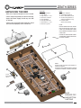
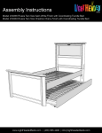
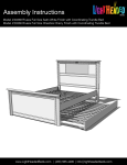
UNPACKING THE BED
• Make sure all parts/components are included.
• Check all bed components for obvious damage.
• Inspect the Power Supply Cord for any cuts and/
or damage.
• Check to see all actuator/motor cables are routed
and connected properly to the control box.
DISCARD
1. Middle Foam Block
2. Large Block
3. Large Cable Tie - CUT
4. Notched 2 x 4 Board
5. Foam Wrapping
6. End Caps with Foam
7. Small Cable Tie - CUT
8. Notched Leg Foam
KEEP
9. Wireform Wallsaver
10. Two Mattress Retainers
11. Service Manual/Documents
12. Trendelenberg Brackets &
Attaching Hardware in bag
13. Pendant Holster
(attached to pendant)
NOTE:
END OF POWER CABLE IS COILED
FOR SHIPPING AND TIED, WITH
CABLE TIE, TO GRID WIRE ALONG
WITH PENDANT, PENDANT CABLE
& HOLSTER.
2
9
PLEASE CUT AND DISCARD CABLE
TIE AROUND CABLES WHEN YOU
UN-PACK THE BED.
4
3
6
1
7
5
10
6
10
NOTE:
Underbed Light is optional and available on
APS981741 Models.
Underbed Light and Mounted Battery optional
combination is available on APS981742 Models.
13
8
Cut and
discard
cable tie.
12
11
8
GF Health Products, Inc. - www.grahamfield.com
ALSO
DISCARD TOP
AND BOTTOM
CARTONS
9
Zenith Series Service Manual 999-0831-190C DEC. 2013
ZENITH SERIES
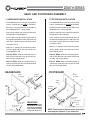
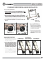
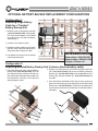
HEAD- AND FOOTBOARD ASSEMBLY
1. HEADBOARD INSTALLATION
2. FOOTBOARD INSTALLATION
• The headboard comes with four pre-installed
inserts - consider this the inside of the board.
• The footboard comes with four pre-installed
inserts - consider this the outside of the board.
• Position 2 mounting tubes on the outside of
the headboard with “L” facing inward.
• Position 2 mounting tubes on the inside of the
footboard with “L” facing outward.
• Align the top hole of the mounting tubes with
the top holes in the headboard.
• Align the top hole of the mounting tubes with
the top holes in the footboard.
• Insert a 40mm hex drive bolt through each of
the top holes and bottom holes and screw into
each insert. Tighten with the Hex Allen wrench
included in the kit.
• Insert a 40mm hex drive bolt through each of
the top holes and bottom holes and screw into
each insert. Tighten with the Hex Allen wrench
included in the kit.
• Slide the “L” portions of the Mounting tubes
into the hollow ends of the main frame rails,
at the head deck end.
• Slide the “L” portions of the Mounting tubes
into the hollow ends of the main frame rails,
at the foot deck end.
• FOR 80” BEDS: Slide the mounting tubes in
until the first tube hole lines up with the first
rail hole. See sample below.
• FOR 80” BEDS: Slide the mounting tubes in
until the first tube hole lines up with the second
rail hole. See sample below.
• FOR 76” BEDS: Slide the mounting tubes in
until the first tube hole lines up with the second
rail hole. See sample below.
• FOR 76” BEDS: Slide the mounting tubes in
until the first tube hole lines up with the third
rail hole. See sample below.
HEADBOARD
FOOTBOARD
Inserts
on inside
CENTER
OF BED
Inserts
on outside
40mm
Bolts
40mm
Bolts
CENTER
OF BED
76” hole position
(3rd hole in)
76” hole position
(2nd hole in)
80” hole position
(1st hole in)
1st hole
IMPORTANT:
76” OR 80”HEADBOARD &
FOOTBOARD POSITIONS
MUST MATCH RETAINER
& WALLSAVER POSITIONS.
PLEASE SEE PAGES 11-12.
GF Health Products, Inc. - www.grahamfield.com
80” hole position
(2nd hole in)
1st hole
NOTE: The first hole at the foot end is reserved for
attaching the Optional 4” pan extension.
10
Zenith Series Service Manual 999-0831-190C DEC. 2013
ZENITH SERIES
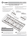
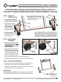
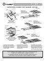
STANDARD MATTRESS RETAINER INSTALLATION
(Using 2 Retainers 999-0844-124)
1. Determine if you need to position your bed in an 80” or 76”
configuration (80” outside holes; 76” inside holes - see
Closeups A & B).
4. On the head end, carefully squeeze the Mattress Retainer ends
inward, toward the center of the retainer, and insert the ends
into the proper holes (see Closeups A & B).
2. On the foot end, carefully squeeze the Mattress Retainer
ends inward, toward the center of the retainer, and insert
the ends into the proper holes (see Closeups A & B).
5. Lay the Mattress Retainer down so that the elbows rest on the
decks and the long cross rod is on the foot end side as shown.
3. Lay the Mattress Retainer down so that the
elbows rest on the decks and the long cross
rod is on the foot end side as shown.
CLOSEUP A:
INSERT HEAD END
MATTRESS RETAINER
CLOSEUP B:
INSERT FOOT END
MATTRESS RETAINER
Ou
Ins tside
ide
h
ho oles
les
f
for or 80
76 ” B
” B ed
ed s
s
IMPORTANT
MAKE SURE ALL THREE ADJUSTABLE PARTS
ARE PROPERLY POSITIONED FOR 76” OR 80”
CONFIGURATIONS (SEE PAGES 10 AND 12)
!
Be sure to use a mattress that is properly sized to fit
the sleep deck, which will remain centered on the deck
relative to State and Federal Guidelines. Use of an improperly fitted mattress could result in injury or death.
GF Health Products, Inc. - www.grahamfield.com
!
Use a properly sized mattress in order to minimize
the gap between the side of the mattress and assist
devices. This gap must be small enough to prevent
resident/patient from getting his/her head or neck
caught in this location.
11
Zenith Series Service Manual 999-0831-190C DEC. 2013
ZENITH SERIES
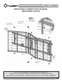
STANDARD WIREFORM WALLSAVER INSTALLATION
WALLSAVER ASSEMBLY
1. Position the Wireform Wallsaver (Part 999-0844-180) with bent
end facing upward and tab ends facing inward as shown at right.
2. Determine the position desired (See bottom of page).
HEAD END
3. Gently squeeze the tab ends of the wallsaver inward toward the
center of the wallsaver and, holding the tabs parallel with the slots
in the caster bases (See DETAIL A), slide the tabs into the slots
while letting the wallsaver gently expand outward.
Start with tab held
6WDUWZLWKWDEKHOG
horizontally
KRUL]RQWDOO\
WALLSAVER POSITIONS
1. The APS 9000 wallsaver features
3 positions for easy reconfiguration
- 76”, 80”, and Trapeze.
2. For 76” beds, position the wallsaver
ends in the caster base slots closest
to the FOOT end of the bed. For 80”
beds, position the wallsaver ends
in the MIDDLE slots on the bases.
GF Health Products, Inc. - www.grahamfield.com
76” Bed Wallsaver
Position w/o Trapeze
'(7$,/%
999-0844-180
%HQGIDFHVXSZDUG
Bend
faces upward
WALLSAVER REMOVAL
1. To remove or move the Wireform
Wallsaver to a new position, raise
the wallsaver off the floor until
the end tabs are horizontal.
2. Squeeze the ends toward the
center of the wallsaver until the
end tabs slide out of the caster
base slots.
76” Bed Wallsaver
Position w/Trapeze or
80” Bed w/o Trapeze
80” Bed Wallsaver
Position w/Trapeze
HEAD END
3. If you have an optional Trapeze unit
on a 76” bed, position the wallsaver
ends in the MIDDLE slots on the
caster bases. For 80” beds position
wallsaver in slots closest to HEAD.
Finish
with
(QGZLWK
Wallsaver
:DOOVDYHU
resting
on
UHVWLQJRQ
floor
IORRU
Wallsaver
:LUHIRUP:DOOVDYHU
Wireform
FOOT END
'(7$,/$
4. Turn the wallsaver downward until it rests on the floor (See
Detail B).
12
Zenith Series Service Manual 999-0831-190C DEC. 2013
ZENITH SERIES
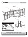
OPTIONAL WALLSAVER ADAPTOR BRACKET INSTALLATION TO
USE WITH TRENDELENBERG/REVERSE TRENDELENBERG FEATURE
3
STEP 1. BRACKET
INSTALLATION
1. Remove the tall Lock Nut (#1)
from the head end of both the
right and left-hand caster bases.
2
1
3
2. Position the two saddle
adaptor brackets (#2
- 999-0831-002) so
that the ends with
slots face away from
the bases as shown.
2
NOTE: MOUNTING OF THE ADAPTOR
BRACKETS IS ONLY NECESSARY IF YOU
PLAN ON USING THE TRENDELENBERG/
REVERSE TRENDELENBERG FEATURE.
1
'(7$,/$
STEP 2. WALLSAVER
ASSEMBLY
1. Position the Wireform Wallsaver
(Part 999-0844-180) with bent
end facing upward and tab ends
facing inward as shown at right.
2. Gently squeeze the tab ends of
the wallsaver inward toward the
center of the wallsaver and, hold
-ing the tabs parallel with the
slots in the caster bases (See
DETAIL A), slide the tabs into the
slots while letting the wallsaver gently expand outward.
6WDUWZLWK
WDEKHOG
KRUL]RQWDOO\
Finish
with
(QGZLWK
Wallsaver
:DOOVDYHU
resting
on
UHVWLQJRQ
floor
IORRU
'(7$,/%
3. Lower the brackets
onto the caster bases,
aligning holes in brackets
with caster stems.
4. Secure brackets to caster bases
using short Nylon Lock Nuts (#3
- 100-6744-002) included in your
adaptor bracket bag/kit.
3. Turn the wallsaver downward until it rests on the floor (See Detail B).
STEP 3. WALLSAVER REMOVAL
1. To remove or move the Wireform Wallsaver to a new position, raise
the wallsaver off the floor until the end tabs are horizontal.
2. Squeeze the ends toward the center of the wallsaver until the
end tabs slide out of the caster base slots.
IMPORTANT:
WALLSAVER END NEAREST THE WALL MUST FACE UPWARD
AS SHOWN FOR WALLSAVER TO SEAT PROPERLY IN SLOTS.
Wireform Wallsaver
:LUHIRUP:DOOVDYHU
999-0844-180
Bend faces upward
%HQGIDFHVXSZDUG
GF Health Products, Inc. - www.grahamfield.com
13
Zenith Series Service Manual 999-0831-190C DEC. 2013
ZENITH SERIES
PLUGGING IN THE FOOTBOARD NURSE/STAFF CONTROL
STEP 1 - ATTACHING THE FOOTBOARD
The APS 9000 bed features a Nurse/Staff Controller in the footboard, however the board is ordered separately with your
bed because of the variety of board styles available. If ordered at the same time as the bed, the Staff Control Assembly
and Shroud Cover will be pre-installed to the Footboard at the manufacturing factory.
STEP 2 - CONNECTING YOUR CABLES
Please refer to DETAIL A shown below.
a. If the Staff Control Assembly is not installed at the
factory you will need to first attach it to the footboard.
b. With the cutout side of the footboard facing outward
as shown, insert the staff control cable through the
large round hole.
c. With the text right-side-up, insert the Staff Control
Assembly into the cutout slot on the footboard and
attach to the board using the two outside small holes
and two screws from your staff control hardware kit.
d. Attach the Shroud Cover over the cable on the
inside of the board using the four remaining screws
from your kit.
e. Insert the T-Cable end (extending out the foot end
with phone jack) into the round plug, making sure
the phone jack is seated correctly inside the female
plug (arrow to arrow - See DETAIL B).
6WDII&RQWURO
Staff Control
$VVHPEO\
Assembly
3KLOOLSV6FUHZV
Phillips
Screws
DWWDFK6KURXG
attach
Shroud
6WDII&RQWURO
& $VVHPEO\IURP
Staff Control
Assembly
from
LQVLGHRIERDUG
inside of board
)227
(1'
Shroud
6KURXG
&DEOH&RYHU
(Cable
Cover)
&DEOH7LH
Cable Tie
6WDII&RQWURO
Staff Control
$VVHPEO\
Assembly
FDEOHWR
cable to
PRXQWLQJWXEH
mounting tube
)RRW%RDUG
Foot
Board
ZLWKFXWRXW
with
cutout
f. Screw on the round lock cap onto
the Staff Control’s female plug to
secure (See DETAIL B).
Loop
Male Staff Control Cable
/RRS0DOH6WDII&RQURO&DEOH
and
cable tie through mounting
DQGFDEOHWLHWKURXJKPRXQWLQJ
tube
hole with Female Staff
WXEHKROHZLWK)HPDOH6WDII
&RQWURO&DEOH
Control
Cable.
g. IMPORTANT:
Make sure to tie
off the staff control
cable to the footboard mounting
tube with a cable
tie as shown.
DETAIL A:
CLOSEUP OF STAFF
CONTROL CABLE CONNECTION
GF Health Products, Inc. - www.grahamfield.com
SEE PAGE 10 OF THIS
MANUAL FOR PROPER
ASSEMBLY OF ELBOW
MOUNTING BRACKETS
(TUBES) & FOOTBOARD
$OLJQ
$UURZV
)HPDOHHQGRI6WDII&RQWURO
Female
end of Staff Control
$VVHPEO\&DEOHSOXJVLQWR7&DEOH
Assembly
Cable - plugs into T-Cable
/RFNLQJ(QG&DSRQ'RXEOH7&DEOH
Locking
End Cap on Double T-Cable
(QGRI'RXEOH7&DEOHDWIRRWHQG*UH\
End
of Double T-Cable at foot end - Grey
7UXQVRQHLWKHUVLGHRI6HDW3DQ
(“T”
runs on either side of Seat Pan
IRUDWWDFKLQJ\RXU+DQG&RQWUROOHU
for attaching your Hand Controller.
DETAIL B:
MAKE SURE LOCK
END CAPS ARE
SCREWED ON
SECURELY.
14
Zenith Series Service Manual 999-0831-190C DEC. 2013
ZENITH SERIES
APS PENDANT/HAND CONTROLLER OPERATION
BED MODELS APS98174, APS981741 & APS981742
1
2
3
4
5
6
7
8
9
BACKLIT PENDANT
HEAD DECK ANGLE UP BUTTON
HEAD DECK ANGLE DOWN BUTTON
HI/LO UP BUTTON (RAISE ENTIRE BED)
HI/LO DOWN BUTTON (LOWER ENTIRE BED)
KNEE & FOOT DECK ANGLE UP BUTTON
KNEE & FOOT DECK ANGLE DOWN BUTTON
SET TO CHAIR POSITION BUTTON
UNDO CHAIR POSITION BUTTON
OPTIONAL UNDERBED LIGHT BUTTON
OPERATION:
1. To angle the Head Deck upward, PRESS 1.
2. To angle the Head Deck downward, PRESS 2.
3. To raise the Bed Up horizontally, PRESS 3.
4. To lower the Bed Down horizontally, PRESS 4.
5. To angle the Knee/Foot Decks upward, PRESS 5.
6. To angle the Knee/Foot Decks downward, PRESS 6.
7. To put the Bed in the Chair position, PRESS 7.
8. To release the Bed from the Chair position, PRESS 8.
9. To turn the underbed light on or off PRESS THE LIGHT.
BULB ICON near the bottom of the hand controller.
Backlit
Pendant
includes
removable
attachment
hook.
9
Under Bed
Light Button
BACKLIT PENDANT
Linak Model #HB8545V3203-61
BAMP Part # 999-0806-301
Backlit and includes
Underbed Light Button
A Pendant
holster also
comes
standard
with the
APS bed.
NOTE:
THE APS 9000 PENDANT CAN BE PLUGGED INTO THE T-CABLE PLUGS ON EITHER SIDE OF THE BED FOR
EASY ACCESS. THE OPPOSITE SIDE OF THE T-CABLE SHOULD ALWAYS HAVE THE PROVIDED CAP ATTACHED
FOR SAFETY.
THE TWO VERTICAL ENDS OF THE DOUBLE T-CABLE RUN TOWARD THE FOOT END OF THE BED, WITH ONE
VERTICAL END PLUGGING DIRECTLY INTO THE CONTROL BOX (OR UNDERBED LIGHT BOX IF YOUR BED HAS
THAT FEATURE) AND THE OTHER LONGER END RUNS ALONG THE TIE ROD AND EXTENDS OUT THE FOOT END
AND PLUGS INTO YOUR STAFF/NURSE CONTROL CABLE.
THE HAND CONTROLLER DOES NOT FEATURE ANY TRENDELENBERG OR REVERSE TRENDELENBERG BUTTONS.
CONTROLS FOR THIS FEATURE ARE ONLY INCLUDED ON THE STAFF/NURSE CONTROLLER FOR OPTIMUM
SAFETY FOR THE PATIENT.
GF Health Products, Inc. - www.grahamfield.com
15
Zenith Series Service Manual 999-0831-190C DEC. 2013
ZENITH SERIES
BED OPERATIONS - NURSE/STAFF CONTROL PANEL
Press “Underbed Light” button (#14) to turn underbed light on or off.
“Safe Mode” (#15) LED light will glow green automatically once power cord is plugged in.
Green light will blink intermittently for approximately 10 minutes. After 10 minutes of nonactivity HI/LO Lock icons on the nurse/staff control panel will show orange (locked).
1
2
3
4
5
6
7
8
9
10
11
12
13
14
15
ALL LOCKED BUTTON
HEAD DECK UP BUTTON
HEAD DECK DOWN BUTTON
KNEE & FOOT DECK UP BUTTON
KNEE & FOOT DECK DOWN BUTTON
CHAIR POSITION BUTTON
UNDO CHAIR POSITION BUTTON
KEY LOCK/UNLOCK BUTTON
HI/LO (T/TR) LOCKED BUTTON
HI/LO UP BUTTON
HI/LO DOWN BUTTON
TRENDELENBERG
REVERSE TRENDELENBERG
UNDERBED LIGHT BUTTON
SAFE MODE RELEASE BUTTON
LOCK OUT SINGLE FUNCTIONS
To individually lock out the “Head”, “Knee”, “Chair”,
and “HI/LO” functions, press the appropriate top
icon (#2, 3, 4, 10, or 12) button and the “Key” button
at the same time. An orange LED lock symbol will
appear under the related icon.
LOCK SYMBOLS
LOCK SYMBOL
LOCK SYMBOLS
Press “Head”, “Knee”, or “Chair” and “Key” at the same time to unlock individual
lock out functions.
Press “HI/LO Locked” to lock out “HI/LO”, “Trendelenberg”,
and “Reverse Trendelenberg” functions.
Press “HI/LO Locked” and “Key” at the same time
to unlock all HI/LO lock out functions.
LOCK SYMBOLS
LOCK SYMBOL
To “Unlock” any of the individual functions, press the
top icon (#2, 3, 4, 10, or 12) and the “Key” Button
(#8) simultaneously. LED lights will not show up.
LOCK OUT HI/LO FUNCTIONS
To lockout the functions for raising and lowering
the entire bed and tilting the bed for Trendelenberg
positions, press the “HI/LO Locked” (#9) button.
Orange LED lock symbols will appear under the
HI/LO and Trendelenberg icons.
LOCK SYMBOLS
LOCK SYMBOLS
Press “All Locked” and “Key” at
the same time to unlock all functions.
To “Unlock” all HI/LO functions, press the “HI/LO
Locked” button (#9) and the “Key” button (#8)
simultaneously. Orange LED lights will not show up.
LOCK OUT EVERYTHING
To lock out all functions, press the “All Locked”
button (#1). Orange LED lock symbols will appear
under the “Head”, “Knee”, “Chair”, “HI/LO”, and
“Trendelenberg/Reverse Trendelenberg” icons.
To “Unlock” all functions, press the “All Locked”
button (#1) and the “Key” button (#8) simultaneously.
Orange LED lights will not show up.
SAFE MODE:
Green light will show automatically when bed is
plugged in and will blink intermittently during 10
minute “sleep mode”. After 10 minutes of lapsed
time since the last function was used, the LED light
shows green and HI/LO Lock icons will show orange.
The LED will be lit green when Safe Mode automatically engages
when plugging in the bed. Press “Safe Mode” and “Key” to disable
the Safe Mode feature.
GF Health Products, Inc. - www.grahamfield.com
To manually disable the function, hold the “Safe
Mode” button (#15) and “Key” button (#8) at the
same time. Green LED light will go out.
16
Zenith Series Service Manual 999-0831-190C DEC. 2013
ZENITH SERIES
BED OPERATIONS - CHAIR POSITION
3
2
1
1. Make sure the Chair position on the staff
control panel is not locked out (orange
lock icon). To unlock, press the Key icon #1
and Chair icon #2 (or “All Locked” button
#3) at the same time.
4
HEAD
END
2. To move the bed to the Chair position
(foot & knee decks angled up, head deck
angled up, and head of bed tilted upward),
press on the chair icon button (#2).
To release the chair feature and return
the bed back into a horizontal position,
press the flat bar icon (#4).
FOOT
END
The Chair feature
can also be operated
using the Pendant.
(See page 15.)
Up and Down
Buttons for
Chair Position
GF Health Products, Inc. - www.grahamfield.com
17
Zenith Series Service Manual 999-0831-190C DEC. 2013
ZENITH SERIES
BED OPERATIONS - TRENDELENBERG/REVERSE TRENDELENBERG
1
1. Make sure the HI/LO function on the staff
control panel is not locked out (orange
lock icon). To unlock, press the Key icon #1
and HI/LO Locked button #2 at the same
time.
2
3
2. To move the bed to the Trendelenberg
position (foot end up), press on button #3.
4
3. To move the APS bed into the Reverse
Trendelenberg position (head end up),
press on button #4.
)227
(1'
75(1'(/(1%(5*
+($'
(1'
NOTE: THE TRENDELENBERG AND REVERSE
TRENDELENBERG FEATURE CAN ONLY BE
ACCESSED USING THE STAFF CONTROL. IT
CANNOT BE ACCESSED USING THE HAND
CONTROLLER/PENDANT.
+($'
(1'
5(9(56(75(1'(/(1%(5*
)227
(1'
GF Health Products, Inc. - www.grahamfield.com
18
Zenith Series Service Manual 999-0831-190C DEC. 2013
ZENITH SERIES
SECTION B
ASSIST DEVICES
Model APS98174, APS981741,
and APS981742
GF Health Products, Inc. - www.grahamfield.com
19
Zenith Series Service Manual 999-0831-190C DEC. 2013
ZENITH SERIES
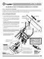
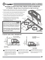
OPTIONAL PIVOT ASSIST BAR INSTALLATION & OPERATION
KIT ZA85400 - (Sample shows bar positioned on left side of bed)
1. At the head end of the bed, position the Pivoting Assist Bar (#2)
bracket over the Head Deck (#1) frame and align the two holes
in the Assist Bar bracket with the two holes in the frame rail on
either side of the head deck.
Position the Assist Bar
Bracket ON TOP of the
Deck Frame, aligning
holes in the bracket with
holes in the frame.
2. From the outside, insert the Clevis Pins (#3) through the
holes in the pivot bracket and deck frame.
+($'
(1'
3. From the inside, insert a Hair Pin Clip (#4) through
each of the small holes in the clevis pins.
1
D
3
D
3
PLEASE ORDER KIT # ZA85400. KIT INCLUDES ONE PIVOTING
ASSIST BAR ASSEMBLY AND TWO LANYARD ASSEMBLIES
WITH CLEVIS PINS AND HAIR PIN CLIPS. (A STATIONARY ASSIST
BAR IS ALSO AVAILABLE AS AN OPTION - KIT # ZA85000).
E
4
E
4
THE ASSIST BAR CAN BE POSITIONED ON EITHER THE RIGHT
SIDE OR LEFT SIDE OF THE HEAD DECK. IT IS NOT OFFERED
FOR THE FOOT END OF THE BED.
1. To release the pivoting assist bar from its
vertical lock position, hold onto the top of
the bar with one hand and slightly pull out
the black knob on the outside of the pivot
assembly with the other hand to release
the locking mechanism. For ease of patient
access, it is recommended that you pivot
the rail toward the headboard until it stops
and rests in place.
PIVOTING ASSIST BAR OPERATION
+($'
(1'
5HFRPPHQG
3LYRW7RZDUG
+HDGERDUG
2. To set the assist bar back to its upright
locked position, grab the top of the assist
bar with one hand and pivot the assembly
upward until the black knob mechanism
snaps into place, locking the assist bar
vertically.
%ODFN.QREWR
/RFNRU5HOHDVH
+($''(&.
6/((3685)$&(
+($'
'(&.
(1'
!
2
FOR OPTIMUM SAFETY, MAKE SURE
FINGERS ARE CLEAR OF THE SIDES
OR UNDERNEATH THE PIVOTING
ASSEMBLY WHEN POSITIONING THE
ASSIST BAR UP OR DOWN.
GF Health Products, Inc. - www.grahamfield.com
!
PLEASE MAKE SURE THE PIVOTING
ASSIST BAR IS ALWAYS IN THE FULL,
VERTICAL, LOCKED POSITION WHENEVER RESIDENT/PATIENT IS LEFT
UNATTENDED.
!
+($'
'(&.
(1'
POWERED AIR MATTRESS SURFACES
MAY POSE A RISK OF ENTRAPMENT.
PRIOR TO USE, ENSURE THE THERAPEUTIC BENEFITS OUTWEIGH THE
RISK OF ENTRAPMENT.
20
Zenith Series Service Manual 999-0831-190C DEC. 2013
ZENITH SERIES
OPTIONAL PLASTIC HALF RAIL INSTALLATION & OPERATION
KIT ZA84200 - (Sample shows rail positioned on right side of bed)
RH Plastic Half Rail
Assembly (#2)
1. Position the Plastic Half Rail (#2) as shown, with the taller, straight edge
toward the head end of the bed and arms angled toward center of the bed.
2. From the outside, insert the two welded pins (with grooves) on the
rail arms into the two large holes in the side of the head deck.
3. From the inside, insert the metal hair pin clip end of the Lanyard
Assembly (#3) onto the exposed grooves at the end of the pins.
4. Position the other terminal end of the Lanyard
Assemblies (#3) over the small hole on the inside
of the deck frame. Secure with a small
threaded Phillips Screw (#4).
PLEASE ORDER PLASTIC RAIL KIT #ZA84200,
WHICH INCLUDES A RIGHT-HAND AND LEFTHAND HALF RAIL, FOUR LANYARD ASSEMBLIES,
AND 2 PHILLIPS SCREWS (OR 2 OPTIONAL HEX
HEAD SCREWS). ORDER BAG # 999-0842-905
FOR JUST THE REPLACEMENT HARDWARE.
Head Deck (#1)
TO
W
AR
OF D C
BE EN
D T
ER
Small
Hole
Lanyard
Assembly (#3)
Straight
Edge toward
Head End
Phillips
Screw (#4)
Lanyard
Assembly (#3)
THE PLASTIC RAIL CAN BE POSITIONED ON
EITHER THE HEAD OR FOOT DECKS FOR 80”
BEDS. THEY SHOULD ONLY BE PUT ON THE
HEAD END FOR 76” BEDS.
HEAD END
PLASTIC HALF RAIL OPERATION
SLEEP
SURFACE
!
TO AVOID PINCHING FINGERS, HOLD
THE HALF RAIL FROM THE TOP WITH
ONE HAND AND CAREFULLY DEPRESS
THE BLACK RELEASE LEVER WITH
THE OTHER. MAKE SURE THERE ARE
NO OBJECTS IN THE WAY THAT MAY
HINDER THE FULL MOVEMENT OF
THE RAIL.
GF Health Products, Inc. - www.grahamfield.com
SLEEP
SURFACE
!
FOR OPTIMUM SAFETY, PLEASE
MAKE SURE RAIL IS ALWAYS IN
ITS “FULL UP LOCKED” POSITION
WHEN LEAVING THE RESIDENT/
PATIENT UNATTENDED TO AVOID
POSSIBLE INJURY.
!
POWERED AIR MATTRESS SURFACES
MAY POSE A RISK OF ENTRAPMENT.
PRIOR TO USE, ENSURE THE THERAPEUTIC BENEFITS OUTWEIGH THE
RISK OF ENTRAPMENT.
21
Zenith Series Service Manual 999-0831-190C DEC. 2013
ZENITH SERIES
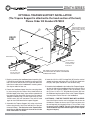
OPTIONAL TRAPEZE SUPPORT INSTALLATION
(The Trapeze Support is attached to the head section of the bed.)
Please Order Kit Number ZA79000
Trapeze Support vertical
support tube. (TMI Bar
Sleeve would be inserted
inside the tube.)
+($'
(1'
0DLQ)UDPH
Use first holes in
Trapeze Support
to mount to main
frame tubes.
Use third hole
from the end of the
main frame tubes.
1. Begin by removing the headboard panel assembly (#2),
if previously assembled to the bed, by pulling out the
two Clevis Pins and two Hair Pin Clips that attach the
main frame tubes to the headboard’s mounting tubes.
Set all pins aside for later use.
2. Detach the headboard panel from the mounting tubes
by unscrewing the four 40mm Allen Head Bolts that
hold the board to the tubes (these will be replaced with
the longer Phillips Head Pan Screws from the trapeze
adaptor hardware bag). Do not remove the (4) four
1/4-20 inserts (#3) from the board. They will be used
again to mount the board to the trapeze support.
3. Assemble the Trapeze Support (#1) to the main frame
tubes using the two Clevis Pins and Hair Pin Clips you
removed in Step 1. The first holes in the Trapeze tubes
must line up with the third hole from the end in the
main frame tubes as shown.
GF Health Products, Inc. - www.grahamfield.com
USE SAME CLEVIS PINS AND HAIR PIN CLIPS
THAT
WERE USED TO CONNECT HEADBOARD
TO MOUNTING TUBES.
4. Insert the 1/4-20 x 2.50” Carriage Bolt (#5) into the vertical
support as shown and fasten with a 1/4-20 Hex Head Lock
Nut (#6). Both parts should be in the hardware bag.
5. Assemble the headboard to the inside of the Trapeze Support
so that the side of the headboard with the inserts is facing
away from the Trapeze Support. From the outside, insert
the (4) four 1/4-20 x 1.75” long Machine Screws (#4) from
the hardware bag through the holes in the Trapeze Support,
screwing them into the inserts in the headboard.
6. OPTIONAL - FOR TMI TRAPEZE BAR WITH SLEEVE:
Insert the Sleeve into the vertical support with the slot on
the bottom. Rotate the sleeve until it falls into place over
the carriage bolt you inserted in Step 4. This will lock it into
the proper position. (NOTE: The top of the Sleeve should
sit flush with the top of the vertical support on the Trapeze
Support Adaptor.)
22
Zenith Series Service Manual 999-0831-190C DEC. 2013
ZENITH SERIES
SECTION C
Mechanical & Electrical
Information
GF Health Products, Inc. - www.grahamfield.com
23
Zenith Series Service Manual 999-0831-190C DEC. 2013
ZENITH SERIES
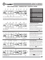
APS 9000 MECHANICS
APS 9000 ELECTRICAL
NOTE: All dimensions are in a range of +/- .25 inches
• Overall Bed Length (with brds & wallsaver) . . 82”/86”
• Overall Bed Width (with boards) . . . . . . . . . . . 36.00”
• Maximum Height* . . . . . . . . . . . . . . . . . . . . . . 30.00”
• Minimum Height* . . . . . . . . . . . . . . . . . . . . . . . 7.00”
• Maximum Head/Back Deck Angle . . . . . . . . . . . . 70°
• Maximum Knee/Foot Deck Angle . . . . . . . . . . . . 30°
• Maximum Safe Working Load . . . . . . . . . . . 600 lbs.
WITH WEIGHT EVENLY DISTRIBUTED
- includes bedding, resident, support surface,
and all accessories.
• Power/Frequency . . . . . . . . . . . . 120 Volt/ 50/60 Hz
• Output Rating . . . . . . . . . . . . . . . . . . . . 12/33V IPX4
• Overall Movement Draw . . . . . . . . . . . . . 4.50 Amps
• Classification . . . . . . . . . . . . . . . . . . . Class I, Type B
• Electrical Cord . . . . . . . . . . . . #18 AWG 3 Conductor
Type SJT
• Mode of Operations
• Battery Backup Option 1
• Mass of bed (without assist devices or boards) = 204 lbs.
* Bed height calculated from floor surface to top of
sleep deck.
. . . . . . . . .10% Max. Duty Cycle
2 minutes on/18 minutes off
. . . . 120V External Battery
Pack and Charger
Pack & Charger purchased separately as an accessory.
• Battery Backup Option 2
. . . . 120V Mounted Battery
Pack is mounted to the bed frame - no charger needed.
TYPICAL APS 9000 BED IDENTIFICATION LABELS
with Grounded Electrical Cable
MODEL NO
GF HEALTH
PRODUCTS, INC.
808-0000-000000
MFG. DATE
4/01/13
ATLANTA, GA 30360
VOLT HZ AMP TYPE
110-120 50/60 4.5
AC
DUTY CYCLE - 2 min Continuous/18 min
MODE OF OPERATION - Intermittent
!
= 600 lbs
SAFE WORKING LOAD
APS98174
MODEL NO. 808-0000-000000
IPX6
ZENITH 808 SERIES
PATENT PENDING
ZENITH APS 9000
SERIAL NO
000000000000
SERIAL ZZ9
MFG DATE 4/01/13
Bed labels are an important part of
identifying the bed’s make and model
when ordering replacement parts. The
Serial Number is essential if you are
claiming parts or service under warranty.
These helpful labels can be located on
the main frame rails, immediately below
the sleep decks on either side of the bed.
Please have this IMPORTANT information ready when calling our customer
service or technical support staff at
800-365-2338; it will allow us to better
assist you and quickly answer your
questions and concerns.
000000000000
ZZ98174
GF Health Products, Inc. - www.grahamfield.com
24
Zenith Series Service Manual 999-0831-190C DEC. 2013
ZENITH SERIES
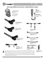
APS 9000 SERIES ELECTRICAL COMPONENTS (LINAK)
MODEL
APS9817406
PENDANT:
Part # 999-0806-301
Quantity = 1
Control/Junction Box
Part # 999-0831-300
Quantity = 1
Power Cable plugs
into side port (part
listed at bottom)
Bed also includes
Pendant Holster
Part # 999-0791-000
Quantity = 1
Head Motor/Actuator
Part # 999-0822-052
Quantity = 1
Foot Motor/Actuator
Part # 999-0822-053
Quantity = 1
Double “T” Cable
Part # 999-0806-200
Quantity = 1
Motor Cable (Hd & HI/LO)
Part # 999-0806-203
Quantity = 3
HI/LO Motor/Actuator
Part # 999-0831-051
Quantity = 2
Motor Cable (Ft.)
Part # 999-0806-202
Quantity = 1
Battery Backup Cable
Part # 999-0831-200
Quantity = 1
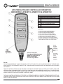
OPTIONAL UNDERBED LIGHT
STANDARD:
3 Prong Power Cable
Part # 999-0775-208
Quantity = 1
!
(APS981741 or -2 Models Only)
Underbed Light Adaptor Cable
Part # 999-0806-212
Quantity = 1
DO NOT use unauthorized parts, accessories, or adaptors other than those specified/authorized by
GF Health Products, Inc. DO NOT open assemblies such as the Actuators, Hand Control, or Control
Box. If unauthorized personnel perform work on these components, the manufacturer’s warranty
becomes void. NEVER operate the bed if a Power Cord or Plug is damaged or not working properly.
Contact qualified Service Personnel for examination and repair. Always unplug the Power Cord when
performing any maintenance on the bed.
GF Health Products, Inc. - www.grahamfield.com
Underbed Light
Part # 999-0806-220
Quantity = 1
25
Zenith Series Service Manual 999-0831-190C DEC. 2013
ZENITH SERIES
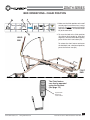
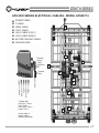
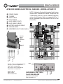
APS 9000 SERIES ELECTRICAL CABLING - MODEL APS98174
u
v
w
x
y
z
{
|
POWER CABLE
T-CABLE
HEAD CABLE
FOOT CABLE
HI/LO CABLE (FOOT)
HI/LO CABLE (HEAD)
BATTERY BACKUP CABLE
GROUND WIRE
Portable
Battery
Cable
Extension
u
|
v
y
{
T-Cable
HI/LO (Ft)
Foot
HI/LO (Hd)
Head
T-Cable (HB)
HI/LO (Ft) - Port 4
Foot - Port 3
HI/LO (Hd) - Port 2
Head - Port 1
x
z
w
Power Cable
Ground
Wire
u
u
v
{
Power Cable &
Battery Cable Side of Control Box
GF Health Products, Inc. - www.grahamfield.com
26
Zenith Series Service Manual 999-0831-190C DEC. 2013
ZENITH SERIES
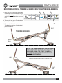
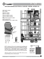
APS 9000 SERIES ELECTRICAL CABLING - MODEL APS981741
u
v
w
x
y
z
{
|
}
POWER CABLE
T-CABLE
HEAD CABLE
FOOT CABLE
HI/LO CABLE (FOOT)
HI/LO CABLE (HEAD)
BATTERY BACKUP CABLE
GROUND WIRE
UNDERBED LIGHT CABLE (UBL)
NOTE: Cabling for Beds with Underbed Light feature
is identical to Standard APS beds, except that the
T-Cable plugs into Port 2 in the Underbed Light Box
and an extra Adaptor Cable is plugged into Port 1
on the Underbed Light Box and the HB Port in the
Control Box.
u
v
v
|
x
z
w
Portable
Battery
Cable
Extension
y
{
v
Ground
Wire
Power Cable
}
v {
UBL-Cable
HI/LO (Ft)
Foot
HI/LO (Hd)
Head
UNDERBED LIGHT (UBL)
Part # 999-0806-220
Adaptor
Cable
Power Cable &
Battery Cable Side of Control Box
Light
T-Cable
T-Cable - Port 2 in Underbed Light Box
HI/LO (Ft) - Port 4 in Control Box
Foot - Port 3 in Control Box
HI/LO (Hd) - Port 2 in Control Box
Head - Port 1 in Control Box
}
(please also order adaptor
cable 999-0806-212)
GF Health Products, Inc. - www.grahamfield.com
27
Zenith Series Service Manual 999-0831-190C DEC. 2013
ZENITH SERIES
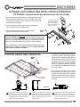
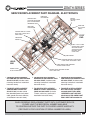
APS 9000 SERIES ELECTRICAL CABLING - MODEL APS981742
u
u POWER CABLE
v T-CABLE
w HEAD CABLE
x FOOT CABLE
y HI/LO CABLE (FOOT)
z HI/LO CABLE (HEAD)
{ BATTERY BACKUP CABLE
| GROUND WIRE
} UNDERBED LIGHT CABLE (UBL)
x
|zy
w
{
v
}
{
Mounted
Battery
Cable
v
Ground
Wire
UBL-Cable
HI/LO (Ft)
Foot
HI/LO (Hd)
Head
Power Cable
{
Underbed Light (UBL)
NOTE: Cabling for Beds with Underbed Light and Mounted
Battery Backup features are identical to Standard APS beds,
except that the T-Cable plugs into Port 2 in the Underbed
Light Box and an extra Adaptor Cable is plugged into Port 1
on the Underbed Light Box and the HB Port in the Control Box.
A Battery Cable runs from the Control Box directly to an
external Battery Pack at the foot end.
GF Health Products, Inc. - www.grahamfield.com
Attached
Battery
Cable
MOUNTED
BATTERY
OPTION
999-0831-003
28
Zenith Series Service Manual 999-0831-190C DEC. 2013
ZENITH SERIES
SECTION D
SERVICE/REPLACEMENT
PARTS
GF Health Products, Inc. - www.grahamfield.com
29
Zenith Series Service Manual 999-0831-190C DEC. 2013
ZENITH SERIES
SERVICE/REPLACEMENT PART RECORD (Page 1)
DECKING
Part Number
Description
QTY
999-0844-920SP
Head/Back Deck & Hardware Pack
1 Deck
999-0844-930SP
OR - Foot Deck & Hardware Pack
1 Deck
999-0844-940SP
OR - Knee Deck & Hardware Pack
1 Deck
Deck Hardware Pack - INCLUDES . . .
1 Pkg
Separate
Hardware Pack
999-0844-990
4
Clevis Pins
5
5/16” Retaining Rings (Deck Brackets)
2
12mm Retaining Ring (Cntrl Arms to Decks)
1
Installation Instruction Sheet
Order Date
Price
Order Date
Price
Order Date
Price
Order Date
Price
MOTORS (ACTUATORS)
Part Number
Description
QTY
999-0831-051SP
HI/LO Motor (Cable attached) & Hardware Pack
1 Motor
999-0822-052SP
OR - Head Motor (Cable attached) & Hardware Pack
1 Motor
999-0822-053SP
OR - Foot Motor (Cable attached) & Hardware Pack
1 Motor
Motor Hardware Pack- INCLUDES . . .
1 Pkg
Separate
Hardware Pack
999-0844-991
2
12mm Retaining Rings
2
Hair Pin Clips
2
Snap Rings
8
Standard Cable Ties
1
Installation Instruction Sheet
CONTROL BOX & POWER CABLES
Part Number
Description
QTY
999-0831-300
Linak Control Box
1 Box
999-0775-208
Detachable 3-Prong Power Cable
1 Cable
999-0775-206
Optional 2-Prong Power Cable (no ground)
1 Cable
PENDANT/HAND CONTROLLER
Part Number
Description
QTY
999-0806-301
Backlit Pendant/Hand Controller
1 Pendant
999-0791-000
Pendant Holster
1 Holster
OPTIONAL UNDERBED LIGHT & ADAPTOR CABLE
999-0806-220
Underbed Light
1 Unit
999-0806-212
Underbed Light Adaptor Cable
1 Cable
GF Health Products, Inc. - www.grahamfield.com
30
Zenith Series Service Manual 999-0831-190C DEC. 2013
ZENITH SERIES
SERVICE/REPLACEMENT PART RECORD (Page 2)
DOUBLE T-CABLE
Part Number
Description
QTY
999-0806-200SP
Grey Double “T” Control Cable
1 Pack
Double “T” Cable Hardware Pack - INCLUDES . . .
1 Pkg
Separate
Hardware Pack
999-0844-993
1
Split Stem Cable Retainer (Bumper)
2
Push Cable Ties
6
Standard Cable Ties
1
Installation Instruction Sheet
Order Date
Price
BATTERY BACKUP CABLE & BATTERY BACKUP PACK (NOT-STANDARD)
Part Number
Description
QTY
999-0831-003
Battery Pack (Portable or Mounted)
1 Pack
999-0831-200
Battery Backup Cable (Needed for Portable Battery Pack)
1 Cable
Order Date
Price
Order Date
Price
Order Date
Price
STAFF CONTROL
Part Number
Description
QTY
999-0877-901
Switch Pad with Bezel & Cables
1 Unit
ZL877000
Staff Control Service Pack - INCLUDES . . .
1 Pkg
PLEASE SEE
PAGE 14
FOR
INSTALLATION
INSTRUCTIONS
1
Switch Pad with Bezel & Cables
1
Shroud (Cable Cover)
6
#6 Phillips Head Truss Screws
3
4” Nylon Cable Tie
1
Installation Instruction Sheet
CAPS & PLUGS
Part Number
Description
QTY
NOTE: CAPS & PLUGS CAN ONLY BE PURCHASED IN SETS OF 12
100-4200-004PK
1.25” x 1.25” Square Caps Pack
12/pkg
100-4700-015PK
1.00” x 1.00” Square Caps Pack (arm ends)
12/pkg
100-4700-017PK
1.00” x 2.00” Rectangular Caps Pack
12/pkg
100-4700-021PK
.75” x 1.50” Rectangular Caps Pack
12/pkg
100-4700-018PK
1.25” x 2.00” Rectangular Caps Pack
12/pkg
100-4715-011PK
1.50” Round End Caps Pack (cover arm bearings)
12/pkg
999-0775-001PK
Half Moon End Caps Pack (caster bases)
12/pkg
100-4762-002PK
5/8” Round Plugs Pack (both sides of foot deck)
12/pkg
100-4738-005PK
3/8” Round Plugs (on main frame rails - foot end)
12/pkg
FOR GENERAL CAP/PLUG DIAGRAMS PLEASE SEE PAGES 36 & 37
GF Health Products, Inc. - www.grahamfield.com
31
Zenith Series Service Manual 999-0831-190C DEC. 2013
ZENITH SERIES
SERVICE/REPLACEMENT PART DIAGRAM - ELECTRONICS
FOOT-END
HI/LO MOTOR
END OF
BATTERY CABLE
(BLACK)
CONTROL BOX ATTACHED TO MOTOR
(MAY HAVE OPTIONAL
UNDERBED LIGHT)
FOOT-END
OF T-CABLE
(GREY)
HEAD-END
HI/LO MOTOR
LONGER SIDE OF T-CABLE
WITH PUSH CABLE TIE IN
SMALL HOLE
FOOT
END
FOOT/KNEE
MOTOR
LONG “T” OF T-CABLE
AND BATTERY CABLE
SECURED TO ROD
AND MAIN FRAME
BRACKET WITH
CABLE TIES
FOOT MOTOR
HEAD
END
POWER CABLE
PLUG AT HEAD END
SHORTER SIDE OF T-CABLE WITH
PUSH CABLE TIE IN SMALL HOLE
CABLE PROTECTION GROMMET
IN SEAT PAN KEY HOLE
POWER CABLE SECURED TO ROD
WITH CABLE TIES
1. TO ORDER A REPLACEMENT
HI/LO MOTOR USE SERVICE PACK
999-0831-051SP (Includes motor,
mounting hardware & installation
instruction sheet).
2. TO ORDER A REPLACEMENT
HEAD MOTOR USE SERVICE PACK
999-0822-052SP (Includes motor,
mounting hardware & installation
instruction sheet).
3. TO ORDER A REPLACEMENT
FOOT MOTOR USE SERVICE PACK
999-0822-053SP (Includes motor,
mounting hardware & installation
instruction sheet).
4. TO ORDER A REPLACEMENT
CONTROL BOX PLEASE USE
999-0831-300 (Includes control
box, detachable power cord, control
cable, ground wire screw, cable ties,
& installation instruction sheet).
5. TO ORDER A REPLACEMENT
DOUBLE T-CABLE USE SERVICE
PACK 999-0806-200SP (Includes
T-Cable, cable ties, grommets &
installation instruction sheet).
6. TO ORDER A REPLACEMENT
BATTERY CABLE USE PART
999-0844-200SP. FOR A NEW
UNDERBED LIGHT USE PART
999-0806-220. FOR A NEW LIGHT
BOX CABLE USE 999-0806-212.
WHEN ORDERING REPLACEMENT PARTS WITH CUSTOMER SERVICE,
PLEASE HAVE THE BED SERIAL NUMBER AVAILABLE
TO CONFIRM WHETHER THE PART IS COVERED UNDER WARRANTY.
(SEE PAGE 24 FOR LOCATION OF SERIAL NUMBER ID LABEL.)
GF Health Products, Inc. - www.grahamfield.com
32
Zenith Series Service Manual 999-0831-190C DEC. 2013
ZENITH SERIES
OPTIONAL BATTERY BACKUP REPLACEMENT CONFIGURATIONS
Configuration 1:
Replacing Single Battery
Cable for a “Portable”
Battery Backup Unit
1. Replacing the existing battery backup
cable (Part 999-0831-200) is fairly simple.
First, if the external battery unit is hooked
up, unplug it from the foot-end battery
cable plug (#1).
2. Carefully cut all cable ties (#2).
3. Unplug the existing cable from the Control
Box (#3). Plug in the new cable and run
along same path as previous cable.
4. Use cable ties to re-secure to tie rod and
mounting brackets (#2).
ITEMS SOLD SEPARATELY
Battery Pack = 999-0831-003
Battery Cable = 999-0831-200
Charger = Please call
Configuration 2:
Replacing Mounted Battery Backup Unit (includes attached battery cable)
2. Using a 3/8” socket wrench, remove the two Nylon Lock Nuts
(#6 - Part 100-6725-003) that secure the Battery Mounting
Bracket (#5 - Part 999-0831-001G) to the welded Main Frame
Bracket (#4). Remove the bolts (#7 - Part 100-5225-009) and
set aside.
1. If the APS bed came with a mounted Battery
Backup Pack (Part 999-0831-003) you must
first unplug the power cord from the wall unit,
then unplug the attached battery cable from
the Control Box. Carefully cut all cable ties
along the battery cable.
3. Once the Bracket and Battery Pack (#9) are free, remove the
pack from the bracket by unscrewing the four Phillips Head
Screws (#8 - Part 100-5414-001). Place the new battery pack
on the bracket and reverse the process to reattach bracket
and cable.
GF Health Products, Inc. - www.grahamfield.com
33
Zenith Series Service Manual 999-0831-190C DEC. 2013
ZENITH SERIES
SECTION E
FRAMING SERVICE PARTS
For All Zenith APS 9000 Bed Models
GF Health Products, Inc. - www.grahamfield.com
34
Zenith Series Service Manual 999-0831-190C DEC. 2013
ZENITH SERIES
SERVICE/REPLACEMENT PART DIAGRAM - DECKING
999-0844-920G
Deck Bracket
Retaining
Ring
HEAD DECK
TO MAIN FRAME
SEAT PAN BRACKETS
Seat
Pan
Bracket
(or
second
Deck
Bracket)
Re-use
Existing
Bearing
Seat Pan
Re-use
Existing
Clevis Pin
DETAIL OF DECK
ATTACHMENT
(Similar for all decks)
Re-use Short
Clevis Pins
Retaining
Ring
999-0844-940G
KNEE DECK
TO MAIN FRAME
SEAT PAN BRACKETS
Re-use
Existing
Ratchets
Re-use Long
Clevis Pins
Retaining
Ring
Main Frame
Bracket
999-0844-930G
FOOT DECK
TO KNEE DECK
MOUNTING BRACKETS
DETAIL OF EDEMA
RATCHET RE-ATTACHMENT
(Use existing ratchets
and hardware)
1. TO ORDER A REPLACEMENT
HEAD DECK USE SERVICE PACK
999-0844-920SP (includes deck,
mounting hardware & installation
instruction sheet).
2. TO ORDER A REPLACEMENT
KNEE DECK USE SERVICE PACK
999-0844-940SP (includes deck,
mounting hardware & installation
instruction sheet).
3. TO ORDER A REPLACEMENT
FOOT DECK USE SERVICE PACK
999-0844-930SP (includes all deck,
mounting hardware & installation
instruction sheet). Re-use existing
edema ratchets & ratchet hardware.
WHEN ORDERING REPLACEMENT PARTS WITH CUSTOMER SERVICE,
PLEASE HAVE THE BED SERIAL NUMBER AVAILABLE
TO CONFIRM WHETHER THE PART IS COVERED UNDER WARRANTY.
(SEE PAGE 24 FOR LOCATION OF SERIAL NUMBER ID LABEL.)
GF Health Products, Inc. - www.grahamfield.com
35
Zenith Series Service Manual 999-0831-190C DEC. 2013
ZENITH SERIES
SERVICE/REPLACEMENT PART DIAGRAM MAIN FRAME CAPPING
DETAIL A
SCALE 1 : 5
2X 100-4738-005
Round Plug (Cap)
6X 100-4700-017
Rectangular Cap
2X 100-4700-018
Rectangular Cap
HEAD
END
Seat Pan
FOOT
END
Main Frame Rail
- Foot End
CAPS OR PLUGS ARE NOT COVERED UNDER WARRANTY
(PACKS OF 12 CAN BE ORDERED IN THE EVENT YOU DAMAGE OR LOSE
ANY CAPS/PLUGS ON THE BED - SEE BOTTOM OF PAGE 31 FOR ORDER NUMBERS)
GF Health Products, Inc. - www.grahamfield.com
36
Zenith Series Service Manual 999-0831-190C DEC. 2013
ZENITH SERIES
SERVICE/REPLACEMENT PART DIAGRAM CAPPING ON HEAD, KNEE, AND FOOT DECKS
4x 100-4762-002
5/8” Round Plugs (Caps)
Sides of Foot Deck Only
12x 100-4200-004
Square Caps in
ends of all Decks
CAPPING ON ARMS & LEGS
2X 100-4700-018
End Caps
2X 100-4700-018
Rectangular End Caps
4X 100-4715-011
Round End Caps
2X 100-4700-021
Rectangular End Caps
CAPS OR PLUGS ARE NOT COVERED UNDER WARRANTY
(PACKS OF 12 CAN BE ORDERED IN THE EVENT YOU DAMAGE OR LOSE
ANY CAPS/PLUGS ON THE BED - SEE BOTTOM OF PAGE 31 FOR ORDER NUMBERS)
GF Health Products, Inc. - www.grahamfield.com
37
Zenith Series Service Manual 999-0831-190C DEC. 2013
ZENITH SERIES
SECTION E
TROUBLESHOOTING
All Zenith APS 9000 Models
GF Health Products, Inc. - www.grahamfield.com
38
Zenith Series Service Manual 999-0831-190C DEC. 2013
ZENITH SERIES
TROUBLESHOOTING - NOTHING WORKS - NO POWER
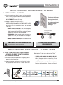
1. NOTHING WORKS - NO POWER
a. Check to make sure there is power coming from the
outlet. Unplug the power cable from the outlet and test
the outlet by plugging in a lamp or similar portable device.
OUTLET WORKS = move to Step b.
b. Replug the power cord into the outlet NOTHING WORKS - UNPLUG THE POWER CORD
and check the power cord from the head end to the control
box, making sure it is not pinched, frayed, or damaged
in any way.
- POWER CORD IS PINCHED = With cord unplugged,
try to move the bed part slightly to release the pinched
cord. If you can release the cord, re-plug the power
cord into the wall outlet and test the bed.
Test Outlet for Power.
Unplug Power Cord
and check entire cord
to make sure it is not
pinched, frayed, or
damaged.
3-Prong Power Cable
999-0775-208
- BED WORKS = Make sure the cord is not frayed or
exposed. If it is OK, you should not have to replace.
- POWER CORD IS DAMAGED = Cut cable ties and
immediately replace Power Cord.
!
ALWAYS UNPLUG THE POWER CORD BEFORE DOING
ANY ELECTRICAL WORK ON THE BED.
IF 3-PRONG POWER CORD IS DAMAGED,
REPLACE IMMEDIATELY!
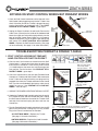
TROUBLESHOOTING STAFF CONTROL - BLINKING LIGHTS
1. STAFF CONTROL LIGHTS ARE BLINKING
- NOTHING ON STAFF CONTROL WORKS
BUT PENDANT WORKS
a. This could mean the staff control is not getting enough
power from the Control Box.
b. Unplug the power cord from the wall outlet. Unplug
the staff control cable from the T-Cable at the foot
end of the bed.
GF Health Products, Inc. - www.grahamfield.com
c. If you have a spare staff control assembly, plug the
cable into the T-Cable at the foot end and test.
- WORKS AND LIGHTS NO LONGER BLINK =
Replace the Staff Control Assembly in the footboard. (See page 42 for dis-assembly. Please
see page 31 for order number.)
- DOESN’T WORK & LIGHTS STILL BLINKING =
Replace the Control Box. (Please see Page 30
for order number).
39
Zenith Series Service Manual 999-0831-190C DEC. 2013
ZENITH SERIES
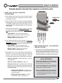
NOTHING ON STAFF CONTROL WORKS BUT PENDANT WORKS
1. Check the Staff Control connections at the foot end. Is the
Staff Control Cable plugged securely into the T-Cable? Also
check if the other end of the T-Cable is plugged securely
into the Control Box (or Underbed Light). If the STAFF
CONTROL STILL DOESN’T WORK = go to step b.
2. Unplug the Power Cord from the wall outlet. Remove the
Cable Cover (Shroud) on the inside of the footboard and
locate the single terminal end that plugs directly into the
back of the Staff Control Panel. Make sure it is properly
seated into the panel. Plug in the power cord and test the
staff control. If the STAFF CONTROL STILL DOESN’T
WORK = Replace the Staff Control Assembly. (See page
42 for dis-assembly. See page 31 for order information.)
6WDII&RQWURO
$VVHPEO\
6WDII&RQWURO
%HYHO
6FUHZV
)RRW%RDUG
ZLWKFXWRXW
6WDII&RQWURO
%HYHO6FUHZV
6KURXG6FUHZV
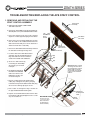
TROUBLESHOOTING PENDANT & DOUBLE T-CABLE
1. STAFF CONTROL WORKS BUT PENDANT/
HAND CONTROLLER FUNCTION DOESN’T
a. Check to see if the functions are locked out on the Staff
Control panel - if orange lock icons show on panel then
that function is locked out. Press the Key and Function
(i.e. Head) button at the same time until the orange lock
icon goes out. Test the function. If the PENDANT STILL
DOESN’T WORK = go to step b.
b. Check the connections at the seat pan (Pendant/Hand
Controller to T-Cable) and Staff Control Cable connection
to the T-Cable at the foot end making sure plugs are fully
engaged. Also check the T-Cable connection at the Control
Box. If you have an Underbed Light feature, make sure all
cables are secure. If the PENDANT STILL DOESN’T
WORK = move to step c.
If orange lock icon lit, press key symbol and function to unlock.
B
Make sure plugs
are fully seated
(O-ring does
not show).
Make sure plugs at foot
end are fully seated
and cap locked on. B
Unplug Staff Control
Cable from T-Cable
at foot end.
D
C
Unplug
Power
Plug
before
working
on bed
electronics.
c. UNPLUG THE POWER CORD FROM THE WALL OUTLET.
d. Unplug the Pendant/Hand Controller plug from the end of
the T-Cable on either side of the beds Seat Pan. Unplug
the Staff Control Cable from the end of the T-Cable at the
foot end of the bed and unplug the other end from the
Control Box.
e. Plug the Pendant/Hand Controller plug directly into the HB
port on the Control Box, making sure it is fully seated.
Plug in the Power Cord and test the Pendant.
A
E
Plug Pendant Cable directly into HB port on Control Box
(or into port 2 in Underbed Light Box) and test.
E
- ALL BUTTONS WORK = Replace the T-Cable
(See page 31 for order information.)
- NOTHING WORKS = Replace the Hand Controller.
(See page 30 for order information.)
GF Health Products, Inc. - www.grahamfield.com
40
Zenith Series Service Manual 999-0831-190C DEC. 2013
ZENITH SERIES
TROUBLESHOOTING MOTOR CABLES & CONTROL BOX
1. HEAD, FOOT, OR HI/LO FUNCTION
NOT WORKING
a. Check plugs to make sure they are firmly seated in all ports
on the Control Box and are plugged into the correct ports
(See diagram at right).
POWER PLUG
b. Check all cables to make sure they are not frayed, pinched,
or damaged in any way. If any cable is damaged, UNPLUG
THE BED’S POWER CORD FROM THE WALL OUTLET
and REPLACE THE CABLE AND/OR THE ELECTRONIC
COMPONENT.
4
3
2
1
FOOT HI/LO
FOOT
HEAD HI/LO
HEAD
HB
c. HEAD DECK NOT RAISING - Unplug the power cord. Switch
the head and foot plugs (Ports 1 and 3). Re-plug the power
cord and press the FOOT button to test.
BATTERY
- DOESN’T WORK = Replace the Head Motor.
(See page 30 for order information.)
d. FOOT AND KNEE DECKS NOT RAISING - Unplug the
power cord. Switch the foot and head plugs (Ports 3 and 1).
Re-plug the power cord and press the HEAD button to test.
- FOOT WORKS = Control Box foot port bad.
Replace box (See page 30 for order information.)
- DOESN’T WORK = Replace the Foot Motor.
(See page 30 for order information.)
e. BED DOES NOT GO UP AND DOWN IN HORIZONTAL
POSITION - If you press the Up or Down HI/LO button and
you hear a click or buzz but nothing happens = Check the
HI/LO Motors by touching them & pushing the HI/LO buttons.
- YOU FEEL NOTHING = possible bad motor - go to the
third step below.
- YOU FEEL SLIGHT VIBRATION = Motor OK.
- Unplug the Power Cord = Switch the two HI/LO plugs
(ports 4 and 2) in the Control Box. Re-plug the power cord
and press the same HI/LO button, then touch the same
non-vibrating motor.
i. MOTOR NOW VIBRATES = Bad port in the
Control Box - Replace box. (See page 30 for
order information.)
ii. MOTOR DOES NOT VIBRATE = Replace
the bad HI/LO Motor. (See page 30.)
GF Health Products, Inc. - www.grahamfield.com
T-CABLE
- HEAD WORKS = Control Box head port bad.
Replace box (See page 30 for order information.)
2. BED LOOKS UNLEVEL - HI/LO MOTORS
ARE NOT IN SYNC
a. Press the HI/LO “DOWN” button repeatedly on either
the Staff Control or Pendant/Hand Controller until
the bed goes completely down and rests in its full
horizontal position. The two HI/LO motor shafts
should be completely retracted inside the motors.
QUICK REFERENCE
- HI/LO & FOOT WORKS, BUT HEAD DOES NOT:
Switch Head & Foot Motor Cable at the Control Box
and test (See Step C in left column).
- HI/LO & HEAD WORKS, BUT FOOT DOES NOT:
Switch Foot & Head Motor Cable at the Control Box
and test (See Step D in left column).
- HEAD & FOOT WORKS, BUT HI/LO DOES NOT:
a. Switch Head and Foot HI/LO Motor Cables at the
Control Box and test (See Step E in left column).
b. Test to see if HI/LO Motors need to be re-aligned
(See Step F above).
41
Zenith Series Service Manual 999-0831-190C DEC. 2013
ZENITH SERIES
TROUBLESHOOTING/REPLACING THE APS STAFF CONTROL
1. REMOVING AND REPLACING THE
STAFF CONTROL ASSEMBLY
6WDII&RQWURO
$VVHPEO\
a. UNPLUG THE POWER CORD FROM
THE WALL OUTLET.
b. Unscrew the four Phillips Screws (#1) that attach the
Shroud (cable cover) to the footboard and set aside.
c. At the foot end of the bed, unscrew the retaining
cap on the T-Cable (#3) and unplug the two cables.
6WDII&RQWURO
%HYHO
6FUHZV
)RRW%RDUG
ZLWKFXWRXW
d. Unscrew the two remaining Phillips Screws (#2)
from the inside of the footboard that attach the
Staff Control Assembly bevel to the board. Set
aside screws for later re-assembly.
6WDII&RQWURO
%HYHO6FUHZV
e. Remove the OLD Staff Control Assembly and feed
the old cable out through the large hole.
6KURXG6FUHZV
f. Feed the cable of the NEW Staff Control
Assembly from the outside through the
large hole and insert the bevel into the
cutout on the outside of the footboard.
g. Secure the Staff Control by
re-inserting the two Phillips
Screws (#2) you removed
in Step D.
,03257$175XQD&DEOH
7LHWKURXJKWKHHQGKROHLQ
WKHPRXQWLQJWXEHORRSWKH
H[FHVVFDEOHUXQWKHWLH
DURXQGFDEOHDQGSXOOWLJKW
WRVHFXUH&XWRIIH[FHVV
FDEOHWLH
h. Re-position the Shroud on
the inside of the footboard
and secure with the four
Phillips Screws (#1) you
removed in Step B.
i. Plug the T-Cable (#5) into the Staff Control
Cable (#4), making sure the phone jack plug
is seated correctly into the Staff Control cable plug.
Screw on the retaining cap (#3) to secure.
j. Run a Cable Tie through the large end hole on
the right-hand footboard mounting tube.
k. Loop the excess Staff Control Cable. Run the cable
tie around the cable and pull tight to secure. Cut off
any excess Cable Tie.
GF Health Products, Inc. - www.grahamfield.com
)HPDOHHQG
RI6WDII&RQWURO
&DEOH
End
of Double T-Cable
(QGRI'RXEOH7&DEOH
DWIRRWHQG*UH\
at
foot end - Grey
7UXQVRQHLWKHU
(“T”
runs on either
VLGHRI6HDW3DQ
side
of Seat Pan
IRUDWWDFKLQJ\RXU
for
attaching the
+DQG&RQWUROOHU
Hand Controller.)
/RFNLQJ
(QG&DS
42
Zenith Series Service Manual 999-0831-190C DEC. 2013
ZENITH SERIES
LONG TERM CARE BEDS LIMITED WARRANTY
Products manufactured by Basic American Medical Products are warranted to the original purchaser
to be free of defects in material and workmanship for the warranty period listed below commencing from
the date of shipment.
Zenith9000
APS*
Zenith9000*
Zenith7000*
Zenith5000*
Matrix II
Liberty
Eze-Lok
Flex
Bariatric
Frame
15 years
15 years
15 years
15 years
15 years
15 years
15 years
Motors and
Control Box
5 years
5 years
3 years
3 years
n/a
n/a
2 years
Non-specified
electronics
3 years
3 years
3 years
3 years
n/a
n/a
2 years
Bed mounted
accessories
and unspecified
components
2 years
2 years
2 years
2 years
2 years
2 years
2 years
Headboards and
Footboards
1 year
1 year
1 year
1 year
1 year
1 year
1 year
February 2013
* includes all 230V and Slide-Wide bed models
■ This warranty does not apply to damage resulting from abuse, accident, negligence, misuse,
unsuitable environmental conditions, improper cleaning, or caused by unauthorized alteration,
repair, maintenance, assembly, or installation.
■ The beds should be used only for their intended purpose and maintained according to the
service manual provided with the bed.
■ Basic American’s liability shall not exceed the original purchase price.
■ Any repair work or replacement shall not exceed the warranty duration.
■ Basic American Medical Products will, at its option, repair or replace defective product or
parts, provided that the replacement or return has been previously authorized by Basic
American or one of its divisions under the terms of this warranty.
If you have questions regarding a bed’s warranty, please contact
Basic American Medical Products at 1-800-365-2338.
GF Health Products, Inc. - www.grahamfield.com
43
Zenith Series Service Manual 999-0831-190C DEC. 2013
336 Trowbridge Dr. • Fond du Lac, WI 54937
Customer Service: 1.800.365.2338 • Fax: 920.929.8213
www.grahamfield.com
© 2013 GF Health Products, Inc.
All Rights Reserved
Basic American Medical Products and Zenith
are registered trademarks of GF Health Products, Inc.