1
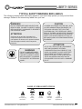
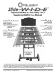
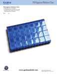
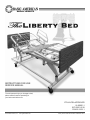
INSTRUCTIONS FOR USE
SERVICE MANUAL
To avoid personal injury or damage to bed,
please read all sections pertaining to
your bed model before use.
ETL/UL/CSA APPROVED
UL 60601-1
IEC 60601-2-38
CSA 22.2 601.1
GF Health Products, Inc. - www.grahamfield.com
Liberty Service Manual 999-0822-190D DEC 2012
This service manual covers the following Liberty Models:
LIberty
76” & 80” Full Electric with Standard Caster System & Grid Decks = LBT7174;
76” & 80” Full Electric with Locking Caster System & Grid Decks = LBTL7174.
Basic American Medical Products
336 Trowbridge Drive
Fond du Lac, WI 54937
For Liberty Bed Service Parts
please contact our Customer Service Department
at 1-800-365-2338
GF Health Products, Inc.
2935A Northwest Parkway
Atlanta, GA 30360
www.grahamfield.com
To order a Liberty Bed
please contact a Graham Field Sales Representative
at 1-800-554-9215
IMPORTANT NOTICE
GF Health Products, Inc. is not responsible for typographical errors.
All illustrations, specifications, packaging, and warranties contained in this Service Manual
are based on the latest product information available at the time of printing.
The most current product information can be found online at www.grahamfield.com.
Please check all parts for shipping damage and test before using.
In case of damage, DO NOT USE.
LIBERTY SERIES
TABLE OF CONTENTS
Safety & Warnings . . . . . . . . . . . . . . . . . . . . . . . . . . . . . 4
Warning Labels . . . . . . . . . . . . . . . . . . . . . . . . . . . . . . . . 5
Recommended Maintenance . . . . . . . . . . . . . . . . . . . . . .6
Liberty Warranty . . . . . . . . . . . . . . . . . . . . . . . . . . . . . . . .6
Entrapment/Compliance . . . . . . . . . . . . . . . . . . . . . . . . . 7
Unpacking Your Bed . . . . . . . . . . . . . . . . . . . . . . . . . . . . .8
Liberty ID/Serial Labels . . . . . . . . . . . . . . . . . . . . . . . . . . .9
Liberty Headboard and Footboard Installation . . . . . . . .10
Standard Mattress Retainer Installation . . . . . . . . . . . . .11
Standard Wallsaver Installation . . . . . . . . . . . . . . . . . . .12
Pendant/Hand Controller Operation . . . . . . . . . . . . . . . .13
Liberty Bed Positions and Deck Elevations . . . . . . . . . .14
One-Step Locking Mechanism Operation . . . . . . . . . . . .15
SECTION A - Liberty with LINAK Electronics . . . . . . 16
- Mechanical & Electronic Specifications
- LINAK Electrical Components
- LINAK Service Part Record
- Bed Diagram with LINAK Electronics
SECTION B - Liberty with ILCON Electronics . . . . . . 22
- Mechanical & Electronic Specifications
- ILCON Electrical Components
- ILCON Service Part Record
- Bed Diagram with ILCON Electronics
SECTION C - Assist Devices/Accessories . . . . . . . . 28
- Fixed and Pivoting Assist Bar Installation
- Foot-end Mounting Bracket and Cross Tubes
- Metal Half Rail Installation
- Trapeze Support Installation
- Foot-end Extension Pan (4.00”)
- One Step Locking Mechanism
SECTION D - Electronic Troubleshooting . . . . . . . . . 38
SECTION E - Framing Service Parts . . . . . . . . . . . . 42
GF Health Products, Inc. - www.grahamfield.com
3
Liberty Service Manual 999-0822-190D DEC 2012
LIBERTY SERIES
IMPORTANT SAFETY AND WARNING INFORMATION
!
This product is a variable height, adjustable mattress
platform, which will provide comfort and convenience
for residents/patients and caregivers in long term
care settings.
!
The MAXIMUM SAFE WORKING LOAD for the
Liberty Bed with weight evenly distributed, including
bedding, resident/patient, support surface, and all
accessories, is 450 lbs.
!
NEVER operate the bed if a Power Cord or Plug is
damaged or not working properly. Contact qualified
Service Personnel for examination and repair. Always
unplug the Power Cord when performing any maintenance on the bed.
!
DO NOT open assemblies such as the Actuators, Hand
Control, or Control Box. If unauthorized personnel
perform work on these components, the manufacturer’s
warranty becomes void.
!
DO NOT use unauthorized parts, accessories, or
adaptors other than those specified/authorized by
GF Health Products, Inc.
!
When operating the High/Low, Knee, or Back Functions
of the bed, ALWAYS ensure that the confined individual
is positioned properly within the confines of the bed.
DO NOT let any extremities protrude over the side or
between the bed rails when performing these functions.
!
DO NOT lower the bed when objects are beneath it.
Failure to inspect under the bed can result in damage
to property or personal injury.
!
The bed’s Pendant Cord MUST BE ROUTED AND
SECURED PROPERLY to ensure it does not become
entangled and eventually severed during use. Also
make sure all electrical cords DO NOT get tangled
around the bed, side rails, or legs during transport or
normal operation of the bed.
!
When using nasal-type or masked-type administering
equipment, all oxygen or air tubing MUST BE ROUTED
AND SECURED PROPERLY to ensure that the tubing
does not become entangled and eventually severed
during the normal operation of the bed.
GF Health Products, Inc. - www.grahamfield.com
!
The bed should ALWAYS be left in its lowest position
when unattended to reduce the risk of injury while getting
in or out of the bed.
!
Keep all moving parts free of obstructions (i.e. blankets/
sheets, heating blankets/pads, wiring, etc.).
!
!
DO NOT use the assist devices as push handles for moving
the bed. Assist devices can be deformed or broken if
excessive side pressure is exerted. Assist devices are not
meant for patients considered as high risks for entrapment
(i.e. patients with pre-existing conditions such as
confusion, restlessness, lack of muscle control, altered
mental status, either organic or medicinal, or a combination thereof). Additional safety measures should be
considered for such high-risk patients.
NEVER permit more than one (1) person on/in the bed
at any time.
!
Body weight should be evenly distributed over the
sleeping surface of the bed. DO NOT allow the patient
to lay, sit, or lean in such a way that their entire body
weight is placed only on the raised head or foot sections
of the bed. This especially applies when repositioning
or transferring a patient in or out of the bed. Increased
risk may occur when the patient’s size and/or weight are
inappropriate for the bed’s dimensions or weight capacity.
!
The bed is intended for use, storage, and transport within
a temperature range of -40˚C to +60˚C. It has a waterresistance rating of IPX4 and IS NOT to be powerwashed or submersed.
Operating Conditions
Operation of the bed is based on the following conditions:
Ambient Temperature of +10˚C to +40˚C; Relative Humidity
of 30% to 75% (Non-condensing); Atmospheric Pressure of
700hPa to 1060hPa; and a Splash Protection of IEC 60529.
Storage
Storage of the bed is based on the following conditions:
Ambient Temperature of -10˚C to 70˚C; Relative Humidity
of 10% to 100%; and an Atmospheric Pressure of 500hPa
to 1060hPa.
Radio Frequency Interference (RFI)
RFI influences most electronic equipment. Caution should be
exercised with regard to the use of portable communications
equipment in the area around such equipment. If RFI causes
erratic behavior, shut the bed off immediately. Leave it off
while the transmission is in progress.
4
Liberty Service Manual 999-0822-190D DEC 2012
LIBERTY SERIES
TYPICAL SAFETY/WARNING BED LABELS
The following warning labels have been placed on your bed to help protect you and your bed from
damage. Please do not remove any labels from your bed.
WARNING!
DO NOT LOWER BED WHEN OBJECTS ARE
BENEATH BED. FAILURE TO INSPECT UNDER
BED CAN RESULT IN DAMAGE TO PROPERTY
OR PERSONAL INJURY.
ATTENTION:
S’assurer de ne pas faire descendre le lit
lorsque des objets se trouvent sous le lit. Ne
pas inspecter le dessous du lit pourrait entrainer
des dommages materiels et des risques de
blessures.
CAUTION
THIS BED IS SUITABLE FOR USE ONLY WITH
OXYGEN ADMINISTERING EQUIPMENT OF
THE NASAL OR MASK TYPE OR A TENT
COVERING ONLY THE UPPER HALF (HEAD
END) OF THE BED. OXYGEN TENT CANOPIES
SHOULD NOT EXTEND BELOW BED SPRING
LEVEL. LOCK HAND CONTROL AT FOOT OF
BED WHEN USING OXYGEN ADMINISTERING
EQUIPMENT.
ATTENTION:
WARNING!
DO NOT LOWER BED WHEN
OBJECTS ARE BENEATH BED.
FAILURE TO INSPECT UNDER
BED CAN RESULT IN DAMAGE
TO PROPERTY OR PERSONAL
INJURY.
CE LIT PEUT ETRE UTILISE UNIQUEMENT
AVEC UN EQUIPMENT DESTINE A
L’ADMINISTRATION D’OXYGENE DE TYPE
NASAL OU MASQUE OU AVEC UNE TENTE
RECOUVRANT SEULEMENT LA MOTTIE
AVENT (TETE) DU LIT. LES COTES DE LAS
TENTE OXYGENE NE DOIVENT PAS SE
PROLONGER PLUS DAS QUE LA SOMMIER
DU LIT.
lABel SyMBOl deFInItIOnS
!
!
Consult
Accompanying
Documents
Safe
Working
Load
GF Health Products, Inc. - www.grahamfield.com
Double
Insulated
Protected
Grounded
Device
Type B
Equipment &
Applied Parts
5
Liberty Service Manual 999-0822-190D DEC 2012
LIBERTY SERIES
RECOMMENDED MAINTENANCE AND INSPECTION
} Electrical Inspection of Control Box
} Maintenance Inspection of All
Components (Receipt of shipment)
(every 3 months)
¨ Make sure all parts/components are included
¨ Check the external power cord that plugs into the control
¨ Check all bed components for obvious damage.
¨ Make sure all attaching hardware is securely tightened.
¨ Inspect the Power Supply Cord for any cuts and/or damage.
¨ Check all electrical connections for any wear or fractures.
¨ Check to see all actuator/motor cords are routed and
¨ Check your external or mounted battery (see page 27)
box for any chafing, cuts, or wear.
(Please see “Unpacking Your Bed” - Page 15).
Replace if needed.
connected properly to the control box.
} Electrical Inspection of Pendant
} Mechanical Inspection of Assemblies
(every 6 months)
and Staff Control (every 3 months)
¨ Inspect all welds on the sleeping surface, frame, and base
¨ Check the pendant cord for any chafing, cuts, or wear.
assemblies for stress fractures.
¨ Check all pendant functions . . .
¨ Inspect all fasteners for wear and looseness.
P
Head raises and lowers properly
¨ IMPORTANT: Lubricate all pivot points, actuator/motor
P
Foot raises and lowers properly
clevis pins, and control arm clevis pins as needed. White
Lithium Grease is recommended.
P
Entire bed raises and lowers properly
P
Bed moves to Chair position properly
P
Bed moves to Trendelenberg and
Reverse Trendelenberg positions properly.
} Mechanical Inspection of Casters
& Pedal Locking Mechanism
(every 3 months)
¨ Check to make sure each button and associated function
¨ Check the pedal locking mechanism to make sure it engages
work properly (i.e. the head section raises when the Head
Up button is activated).
and disengages properly.
¨ Check the bottom foot pads on the foot end casters, making
sure they are clean of debris and undamaged. Replace if needed.
¨ Check all casters to ensure that they roll properly and
are unobstructed.
} Electrical Inspection of Actuators/Motors
(every 3 months)
¨ Check the actuator/motor cords for any chafing, cuts, or wear.
¨ Check the range of movement on all motors to ensure they
do not bind in the Full Up and Full Down positions.
WARRANTY
- 10 Years on Frame
- 2 Years on Motors and Control Box
- 1 Year on Other Electronics
The warranties contained herein contain all the representation and warranties with respect to the subject matter
of this document, and supersede all prior negotiations, agreements and understanding with respect thereto.
The recipient of this document hereby acknowledges and represents that it has not relied on any representation,
assertion, guarantee, warranty, collateral contract or other assurance, except those set out in this document.
GF Health Products, Inc. - www.grahamfield.com
6
Liberty Service Manual 999-0822-190D DEC 2012
LIBERTY SERIES
ENTRAPMENT & COMPLIANCE INFORMATION
On March 10, 2006, the FDA (U.S. Food and Drug Administration) released long-awaited guidelines for reducing the risk
of bed entrapment: “Hospital Bed System Dimensional and
Assessment Guidance to Reduce Entrapment”. The new Guidance
identifies potential entrapment areas and those body parts most
at risk for entrapment; provides design criteria for manufacturers
of new hospital/convalescent beds; recommends particular test
methods to assess the conformance of existing hospital/convalescent bed systems; and answers frequently-asked questions
about entrapment issues.
It is also essential to have the correct bed components/accessories that correspond with the needs of your patient/resident
and the particular bed you have purchased. Matching the correct
bed component that correlates with the regulatory guidelines can
be a daunting task. Our sales team at GF Health Products, Inc.
and our friendly Customer Service Representatives at Basic
American Medical Products can help you sift through the wide
array of compliance and bed options. We will help you determine
which bed/bed part is best for your patient’s/resident’s particular
needs and help you with your compliance issues.
The new Guidance was a result of a long-standing collaboration
between the FDA and the Hospital Bed Safety Workgroup
(HBSW), formed in 1999. GF Health Products, Inc’s LongTerm Care Bed division: Basic American Medical Products, is
an HBSW charter member. As a result of our commitment to
product safety, all our current long-term care beds have been
strictly tested and conform to the new FdA Guidance.
the APS 9000 bed and accessories listed in this
manual are in full compliance with FdA guidelines
for reducing the risk of bed entrapment: “Hospital
Bed System Dimensional and Assessment Guidance
to Reduce Entrapment”.
The guidelines set forth by the FDA Guidance layout specific
dimensional limitations on potentially injury-threatening gaps
and spaces that can occur between bed system components,
such as rails, when not properly installed. GF Health Products,
Inc. and Basic American Medical Products have conformed
to these guidelines from a manufacturing aspect. However,
entrapment issues can often arise when a healthcare provider/
facility has not correctly assembled the components on a bed.
It is essential that the provider/facility fully understand their
responsibility in complying to the guidelines set forth by the
FDA in order to avoid injury. To that end, we have provided
the FDA’s web address at right as a resource for understanding
and following these guidelines for the safety of patients/residents.
GF Health Products, Inc. - www.grahamfield.com
details can be found at www.fda.gov.
7
Liberty Service Manual 999-0822-190D DEC 2012
LIBERTY SERIES
UNPACKING YOUR BED
• Make sure all parts/components are included.
• Check all bed components for obvious damage.
• Inspect the Power Supply Cord for any cuts and/
or damage.
• Check to see all actuator/motor cables are routed
and connected properly to the control box.
DISCARD
1. Cardboard Block
2. Notched Leg Foam
3. Large Blocks
4. Large Cable Tie - CUT
KEEP
5. Pendant Holster, Pendant
& Power Cord - Coiled for
shipping and cable tied to
Grid Wire on Head Deck.
6. One Mattress Retainer
7. One Wireform Wallsaver
8. Panel Mounting Brackets
& Hardware for attaching
Headboard & Footboard
9. Service Manual/Documents
ALSO
DISCARD TOP
AND BOTTOM
CARTONS
GF Health Products, Inc. - www.grahamfield.com
8
Liberty Service Manual 999-0822-190D DEC 2012
LIBERTY SERIES
TYPICAL LIBERTY BED IDENTIFICATION LABELS
with Linak Electronics - LBT7174 or LBTL7174
(Models Manufactured Prior to Sept. 2011- Serial Numbers < to 12020004096)
ETL GF HEALTH
Logo PRODUCTS, INC.
MODEL NO
701-0000-000000
MFG. DATE
08/31/11
ATLANTA, GA 30360
VOLT
120
DUTY CYCLE - 2 min Continuous/18 min
MODE OF OPERATION - Intermittent
!
= 450 lbs
SAFE WORKING LOAD
LBT7174
IPX4
LIBERTY 701 SERIES
PATENT PENDING
LIBERTY 7174
MODEL NO. 701-0000-000000
HZ AMP TYPE
50/60
4
AC
SERIAL NO
000000000000
SERIAL LBT7
MFG DATE 08/31/11
000000000000
Bed labels are an important part of
identifying your bed’s make and model
when ordering replacement parts. The
Serial Number is essential if you are
claiming parts or service under warranty.
These helpful labels can be located on
the main frame rails, immediately below
the sleep decks on either side of the bed.
Please have this IMPORTANT information ready when calling our customer
service or technical support staff at
800-365-2338; it will allow us to better
assist you and quickly answer your
questions and concerns.
LBT7174
TYPICAL LIBERTY BED IDENTIFICATION LABELS
with Ilcon Electronics - LBT7174 or LBTL7174
(Models Manufactured After Sept. 2011- Serial Numbers =/> to 12020004096)
ETL GF HEALTH
INC.
Logo PRODUCTS,
ATLANTA, GA 30360
= 450 lbs
SAFE WORKING LOAD
LBT7174
MODEL NO. 701-0000-000000
701-0000-000000
MFG. DATE
09/01/11
VOLT
120
DUTY CYCLE - 2 min Continuous/18 min
MODE OF OPERATION - Intermittent
!
MODEL NO
IPX4
LIBERTY 701 SERIES
PATENT PENDING
LIBERTY 7174
HZ AMP TYPE
50/60
2
AC
SERIAL NO
000000000000
SERIAL LBT7
MFG DATE 09/01/11
000000000000
Bed labels are an important part of
identifying your bed’s make and model
when ordering replacement parts. The
Serial Number is essential if you are
claiming parts or service under warranty.
These helpful labels can be located on
the main frame rails, immediately below
the sleep decks on either side of the bed.
Please have this IMPORTANT information ready when calling our customer
service or technical support staff at
800-365-2338; it will allow us to better
assist you and quickly answer your
questions and concerns.
LBT777174
GF Health Products, Inc. - www.grahamfield.com
9
Liberty Service Manual 999-0822-190D DEC 2012
LIBERTY SERIES
HEAD- AND FOOTBOARD (PANEL) ASSEMBLY
1. Assemble four inserts (#4) into the outside of both the headboard and footboard if not already
pre-assembled.
2. Assemble a right-hand and a left-hand Board Mounting Bracket (#2 & #3) to the insides of both
the headboard and footboard using four 1/4-20 x 20mm Hex Drive JCB-B Bolts (#5) for each
board. The bolts will go through the four pre-drilled holes on each board into the inserts.
3. Slide the headboard and footboard (with mounting brackets) into the main frame rails.
a) For a 76” bed, align the holes in the brackets with the second holes from the end in the sides
of the main frame rails (See Detail A).
b) For an 80” bed, align the holes in the brackets with the first holes from the end in the sides of
the main frame rails (See Detail A).
4. From the outside of the main frame rails, insert a 5/16 x 1.50” Clevis Pin (#6) through the holes
in the frame rails and brackets on both sides of the bed.
5. Secure the clevis pins by inserting a 1-9/16 Hair Pin Clip
(#7) through each of the holes in the ends of the four pins.
HEADBOARDMOUNTING
FOR 80” BED
FOOTBOARD
FOOTBOARDMOUNTING
FOR 80” BED
HEADBOARD
DETAIL B
MOUNTING
FOR 76” BED
NOTE: To order a new Panel Mounting Kit, please use part # 999-0822-000. Kit includes a right-hand and left-hand
Mounting Bracket, 8 Hex Drive Bolts, 4 Clevis Pins, 4 Hair Pin Clips, and 1 Hex Allen Wrench. Both Panels (Headboard and Footboard) are sold separately.
GF Health Products, Inc. - www.grahamfield.com
10
Liberty Service Manual 999-0822-190D DEC 2012
LIBERTY SERIES
STANDARD FULL-WIDTH MATTRESS RETAINER INSTALLATION
The Liberty Bed’s mattress retainer was designed to span the width of the sleeping surface.
One retainer is shipped with your bed and is typically placed at the foot end, although it will
fit on either end. It is easily attached to the decks by inserting it into the pre-drilled holes for
76” or 80” positions (see insert below).
To order an additional mattress retainer,
please use part # 999-0822-001.
!
Be sure to use a mattress that is properly sized to fit
the sleep deck, which will remain centered on the
deck relative to State and Federal Guidelines. Use
of an improperly fitted mattress could result in injury
or death.
GF Health Products, Inc. - www.grahamfield.com
!
Use a properly sized mattress in order to minimize
the gap between the side of the mattress and assist
devices. This gap must be small enough to prevent
resident/patient from getting his/her head or neck
caught in this location.
11
Liberty Service Manual 999-0822-190D DEC 2012
LIBERTY SERIES
QUICK-INSTALL, VERSATILE HEAD-END WALLSAVER
The Liberty Bed is shipped with a durable wireform wallsaver for the head-end of the bed. No hardware is necessary
for attaching this multi-positional standard accessory.
Simply bend-in the tabbed ends into the slots in the carriage rails and lock down into place. There is even a position if
you choose to install an optional trapeze support at the head end of the bed. (See page 30 for Trapeze Support
installation in the Accessories section of this manual.)
To order additional wireform wallsavers, please use part # 999-0822-180.
WALLSAVER ATTACHING POSITION
FINAL WALLSAVER RESTING POSITION
FLAT TAB LOCKS INTO
THE CARRIAGE RAIL BY
TURNING IT IN SIDE HOLE
UNTIL THE WALLSAVER
RESTS ON CROSSBRACE
FLAT TAB IS INSERTED
SO THAT IT IS PARALLEL
WITH THE SLOT IN THE
CASTER CARRIAGE RAIL
QTY
PART NUMBER
DESCRIPTION
1
999-0822-180
STANDARD WIREFORM WALLSAVER
76” AND 80”
(Also has position for Trapeze Accessory)
GF Health Products, Inc. - www.grahamfield.com
Wallsaver hole for 80” Bed with Trapeze
Wallsaver hole for 76” Bed with Trapeze
Wallsaver hole for 80” Bed without Trapeze
Wallsaver hole for 76” Bed without Trapeze
12
Liberty Service Manual 999-0822-190D DEC 2012
LIBERTY SERIES
STANDARD PENDANT/HAND CONTROLLER OPERATION
Each of the Liberty Beds are equipped with a pendant-type hand control - standard.
Every control function (head/back, knee, and foot) has two easily recognizable
switches for up and down movement. The pendant can be easily dis-connected to
deactivate the patient control functions.
To operate, simply push the appropriate button to activate the desired function (see
diagram at right).
2
1
1
2
3
4
5
6
NON-BACKLIT PENDANT
HEAD DECK ANGLE UP BUTTON
HEAD DECK ANGLE DOWN BUTTON
HI/LO UP BUTTON (RAISE ENTIRE BED)
HI/LO DOWN BUTTON (LOWER ENTIRE BED)
KNEE & FOOT DECK ANGLE UP BUTTON
KNEE & FOOT DECK ANGLE DOWN BUTTON
OPERATION:
1. To angle the Head Deck upward, PRESS 1
2. To angle the Head Deck downward, PRESS 2
3. To raise the Bed Up horizontally, PRESS 3
4. To lower the Bed Down horizontally, PRESS 4
5. To angle the Knee/Foot Decks upward, PRESS 5
6. To angle the Knee/Foot Decks downward, PRESS 6
3
4
5
6
Male End Connector
of Pendant Cable
NON-BACKLIT PENDANT
Model #HB00
Part # 999-0808-305
Pendant Holster
999-0791-000
NOTE:
The easiest method for deactivating the Pendant function is to simply unplug the power cord from
the wall socket or other power supply when the patient is left alone in the bed. When you need to
use the Pendant function to raise or lower the bed or decks, replug the power cord into the power
outlet.
GF Health Products, Inc. - www.grahamfield.com
13
Liberty Service Manual 999-0822-190D DEC 2012
LIBERTY SERIES
LIBERTY BED HI/LO & DECK POSITIONS
The Liberty bed has a variety of positions that serve to help the patient be more comfortable
and gives the practitioner/caregiver easy access during procedures and transfers.
The correct placement of the bed is essential for the patient’s safety.
FOOT
END
The bed should always be set to its lowest position when the resident/patient
is left unattended. The head/back and foot/knee functions allow the
resident/patient to comfortably raise their head or legs. In the event of a power
outage, it is preferred that the knee and head/back sections be lowered
using an emergency battery pack.
HEAD
END
QUICK REFERENCE
Bed Height - floor to sleep deck top
MAXIMUM (High Position) = 24.50”
MINIMUM (Low Position) = 9.95”
Head Deck to Sleep Surface
MAXIMUM (Head Angle) = 70°
Knee Deck to Sleep Surface
MAXIMUM (Knee Angle) = 30°
Knee Deck to Foot Deck
MAXIMUM (Knee/Foot Angle) = 45°
GF Health Products, Inc. - www.grahamfield.com
14
Liberty Service Manual 999-0822-190D DEC 2012
LIBERTY SERIES
LIBERTY BED ONE-STEP LOCKING MECHANISM
OPERATION INSTRUCTIONS
Locked Position
on Your Liberty Bed
To lock the foot end of the Liberty bed,
step on the red pedal until the lock
engages. The green release lever will
show through the slot in the top of the
locking mechanism. To fully lock the
bed, make sure the caster keepers at
the head of the bed are both in their
down positions.
Unlocked Position
on Your Liberty Bed
To unlock the foot end of the Liberty
bed, step on the green release pedal
until the lock disengages. The green
release lever will disappear through
the slot in the top of the pedal locking
mechanism and the red pedal will raise.
To fully unlock the bed, make sure the
caster keepers at the head of the bed
are both in their up positions.
GF Health Products, Inc. - www.grahamfield.com
15
Liberty Service Manual 999-0822-190D DEC 2012
LIBERTY SERIES
SECTION A
Liberty Beds
with Linak Electronics
Models Manufactured Prior to 09/01/2011
(All Beds with Serial Numbers prior to SN12020004096)
GF Health Products, Inc. - www.grahamfield.com
16
Liberty Service Manual 999-0822-190D DEC 2012
LIBERTY SERIES
LIBERTY BED MECHANICS
(All Models)
NOTE: All dimensions are in a range of +/- .25 inches
• Overall Bed Length (with brds & wallsaver) . . 83”/86”
• Overall Bed Width (with boards) . . . . . . . . . . . 36.00”
• High Height* . . . . . . . . . . . . . . . . . . . . . . . . . . 24.50”
• Low Height* . . . . . . . . . . . . . . . . . . . . . . . . . . . 9.95”
• Maximum Head/Back Deck Angle . . . . . . . . . . . . 70°
• Maximum Knee/Foot Deck Angle . . . . . . . . . . . . 30°
• Maximum Safe Working Load . . . . . . . . . . . 450 lbs.
WITH WEIGHT EVENLY DISTRIBUTED
- includes bedding, resident, support surface,
and all accessories.
• Mass of bed (without assist devices or boards) = 182 lbs.
* Bed height calculated from floor surface to top of
sleep deck.
LIBERTY LINAK ELECTRONICS
Prior to 09/01/2011 Mfg Date
(All Beds with Serial Numbers prior to SN12020004096)
• Power/Frequency . . . . . . . . . . . . 120 Volt - 50/60 Hz
• Output Rating . . . . . . . . . . . . . . . . . . . . 12/33V IPX4
• Overall Movement Draw . . . . . . . . . . . . . 4.00 Amps
• Classification . . . . . . . . . . . . . . . . . . . Class I, Type B
• Electrical Cord . . . . . . . . . . . . #18 AWG 3 Conductor
Type SJT
• Mode of Operation . . . . . . . . . .10% Max. Duty Cycle
2 minutes on/18 minutes off
GF Health Products, Inc. - www.grahamfield.com
17
Liberty Service Manual 999-0822-190D DEC 2012
LIBERTY SERIES
LIBERTY ELECTRICAL LINAK COMPONENTS (Prior to 09/01/2011)
Control/Junction Box
Part # 999-0779-300
Quantity = 1
Power Cable plugs
into side port (part
listed at bottom)
VENDOR MODEL
HB00
PENDANT:
Part # 999-0808-305
Quantity = 1
Bed also includes
Pendant Holster
Part # 999-0791-000
Quantity = 1
Head Motor/Actuator
Part # 999-0822-052
Quantity = 1
Knee/Foot Motor/Actuator
Part # 999-0822-053
Quantity = 1
25.50”Motor Cable (Hd.)
Part # 999-0808-204
Quantity = 1
20.00” Motor Cable (Ft.)
Part # 999-0822-204
Quantity = 1
Hi/Lo Motor/Actuator
Part # 999-0778-051
Quantity = 1
8.00” Motor Cable (Hi/Lo)
Part # 999-0778-204
Quantity = 1
STANDARD:
3 Prong Power Cable
Part # 999-0775-208
Quantity = 1
!
DO NOT use unauthorized parts, accessories, or adaptors other than those specified/authorized by GF Health Products, Inc.
DO NOT open assemblies such as the Actuators, Hand Control, or Control Box. If unauthorized personnel perform work on
these components, the manufacturer’s warranty becomes void. NEVER operate the bed if a Power Cord or Plug is damaged or
not working properly. Contact qualified Service Personnel for examination and repair. Always unplug the Power Cord when
performing any maintenance on the bed.
GF Health Products, Inc. - www.grahamfield.com
18
Liberty Service Manual 999-0822-190D DEC 2012
LIBERTY SERIES
SERVICE/REPLACEMENT PART RECORD - WITH LINAK ELECTRONICS
DECKING
Part Number
Description
QTY
999-0822-920SP
Head/Back Deck & Hardware Pack
1 Deck
999-0822-930SP
OR - Foot Deck & Hardware Pack
1 Deck
999-0822-940SP
OR - Knee Deck & Hardware Pack
1 Deck
Deck Hardware Pack - INCLUDES . . .
1 Pkg
4
Short Machine Screws
4
Self-Wrenching Nuts
1
Clevis Pin
1
Circle Cotter
1
Installation Instruction Sheet
Order Date
Price
Order Date
Price
Order Date
Price
Order Date
Price
MOTORS (ACTUATORS)
Part Number
Description
QTY
999-0778-051SP
Hi/Lo Motor (Cable not included) & Hardware Pack
1 Motor
999-0822-052SP
OR - Head Motor (Cable not included) & Hardware Pack
1 Motor
999-0822-053SP
OR - Foot Motor (Cable not included) & Hardware Pack
1 Motor
Motor Hardware Pack - INCLUDES . . .
1 Pkg
2
12mm Retaining Rings
2
Hair Pin Clips
2
Snap Rings
8
Standard Cable Ties
1
Installation Instruction Sheet
999-0808-204
Head Motor Cable
1 Cable
999-0822-204
Foot Motor Cable
1 Cable
999-0778-204
Hi/Lo Motor Cable
1 Cable
CONTROL BOX & POWER CABLES
Part Number
Description
QTY
999-0779-300
Linak Control Box and Clip
1 Box
999-0775-208
Standard 3 Prong Power Cable
1 Cable
PENDANT/HAND CONTROLLER
Part Number
Description
QTY
999-0808-305
Non-Backlit Pendant (Std. Model)
1 Pendant
999-0791-000
Pendant Holster (Std. for all pendants)
1 Holster
GF Health Products, Inc. - www.grahamfield.com
19
Liberty Service Manual 999-0822-190D DEC 2012
LIBERTY SERIES
SERVICE/REPLACEMENT PART RECORD - WITH LINAK ELECTRONICS
MISCELLANEOUS SERVICE BED PARTS
Part Number
Description
QTY
999-0822-012
Spanner Plates
1 Plate
999-0822-031
Pivot Channels
1 Unit
999-0822-036
Leveler Rods
1 Rod
100-8050-008
1/2” E-Style Retaining Rings (for Leveler Rods)
1 Ring
999-0822-001
Mattress Retainer
1 Unit
999-0822-180
Wireform Wallsaver
1 Unit
999-0822-083
18GA Ground Wire
1 Wire
100-5710-019
#10-24 x .375” HWHTC Ground Screws TYP23
1 Screw
100-1100-018
Standard Cable Ties
1 Tie
100-1100-060
Wing-Tip Cable Ties
1 Tie
Order Date
Price
Order Date
Price
Order Date
Price
CASTER CARRIAGE
Part Number
Description
QTY
999-0822-905G
Caster Carriage Weldment
1 Unit
100-6330-062
3” Twin Locking Caster with 7/16-14 Stems (LBT7174)
1 Caster
100-6330-061
3” Twin Non-Locking Caster with 7/16-14 Stems (LBTL7174)
1 Caster
999-0832-980G
One-Step Locking Mechanism (LBTL7174)
1 Unit
100-6744-001
7/16-14 Nylon Lock Nuts (secure caster stems to frame)
1 Nut
CAPS & PLUGS
Part Number
Description
QTY
NOTE: CAPS & PLUGS CAN ONLY BE PURCHASED IN SETS OF 12
100-4700-015PK
1.00” x 1.00” Square Caps Pack
12/pkg
100-4700-017PK
1.00” x 2.00” Rectangular Caps Pack
12/pkg
999-0822-041PK
Black Tube Pivot Caps
12/pkg
FOR GENERAL CAP DIAGRAMS PLEASE SEE PAGES 44 & 45
GF Health Products, Inc. - www.grahamfield.com
20
Liberty Service Manual 999-0822-190D DEC 2012
LIBERTY SERIES
SERVICE/REPLACEMENT PART DIAGRAM - STANDARD BED
WITH LINAK ELECTRONICS
HEAD BOARD
POWER CABLE
SECURED TO FRAME
WITH CABLE TIES
HEAD
MOTOR
HEAD
END
CONTROL BOX ATTACHED TO
HI/LO MOTOR
FOOT/KNEE
MOTOR
SPECIAL
BOARD/PANEL
MOUNTING
BRACKETS
WIREFORM
WALLSAVER
FOOTBOARD
PENDANT CABLE PLUGGED
DIRECTLY INTO CONTROL
BOX AND CABLE TIED TO
EITHER SIDE OF SEAT PAN
FOOT
END
MATTRESS
RETAINER
“STANDARD” CASTER CARRIAGE
WITH FOUR LOCKING CASTERS
1. TO ORDER A REPLACEMENT
HI/LO MOTOR USE SERVICE PACK
999-0778-051SP (Includes motor,
mounting hardware & installation
instruction sheet.)
2. TO ORDER A REPLACEMENT
HEAD MOTOR USE SERVICE PACK
999-0822-052SP (Includes motor,
mounting hardware & installation
instruction sheet.)
3. TO ORDER A REPLACEMENT
FOOT MOTOR USE SERVICE PACK
999-0822-053SP (Includes motor,
mounting hardware & installation
instruction sheet.)
4. TO ORDER A REPLACEMENT
CONTROL BOX PLEASE USE
999-0779-300 (Includes Control
Box and mounting clip. For new
Power Cord use 999-0775-208.)
5. TO ORDER A REPLACEMENT
MATTRESS RETAINER PLEASE
USE 999-0822-001
6. FOR NEW WALLSAVER PLEASE
USE 999-0822-180
FOR ALL OTHER SERVICE PARTS PLEASE REFER TO PAGES 19 - 20
WHEN ORDERING REPLACEMENT PARTS WITH CUSTOMER SERVICE,
PLEASE HAVE YOUR BED’S SERIAL NUMBER AVAILABLE
TO CONFIRM WHETHER THE PART IS COVERED UNDER WARRANTY.
(SEE PAGE 9 FOR LOCATION OF SERIAL NUMBER ID LABEL.)
GF Health Products, Inc. - www.grahamfield.com
21
Liberty Service Manual 999-0822-190D DEC 2012
LIBERTY SERIES
SECTION B
Liberty Beds
with Ilcon Electronics
Models Manufactured After 09/01/2011
(All Beds with Serial Numbers equal to or after SN12020004096)
GF Health Products, Inc. - www.grahamfield.com
22
Liberty Service Manual 999-0822-190D DEC 2012
LIBERTY SERIES
LIBERTY BED MECHANICS
(All Models)
NOTE: All dimensions are in a range of +/- .25 inches
• Overall Bed Length (with brds & wallsaver) . . 83”/86”
• Overall Bed Width (with boards) . . . . . . . . . . . 36.00”
• High Height* . . . . . . . . . . . . . . . . . . . . . . . . . . 24.50”
• Low Height* . . . . . . . . . . . . . . . . . . . . . . . . . . . 9.95”
• Maximum Head/Back Deck Angle . . . . . . . . . . . . 70°
• Maximum Knee/Foot Deck Angle . . . . . . . . . . . . 30°
• Maximum Safe Working Load . . . . . . . . . . . 450 lbs.
WITH WEIGHT EVENLY DISTRIBUTED
- includes bedding, resident, support surface,
and all accessories.
• Mass of bed (without assist devices or boards) = 182 lbs.
* Bed height calculated from floor surface to top of
sleep deck.
LIBERTY ILCON ELECTRONICS
After 09/01/2011 Mfg Date
(All Beds with Serial Numbers equal to or after SN12020004096)
• Power/Frequency . . . . . . . . . . . . 120 Volt - 50/60 Hz
• Output Rating . . . . . . . . . . . . . . . . . . . . . . . 24V IPX4
• Overall Movement Draw . . . . . . . . . . . . . 2.00 Amps
• Classification . . . . . . . . . . . . . . . . . . . Class I, Type B
• Electrical Cord . . . . . . . . . . . . #18 AWG 3 Conductor
Type SJT
• Mode of Operation . . . . . . . . . .10% Max. Duty Cycle
2 minutes on/18 minutes off
GF Health Products, Inc. - www.grahamfield.com
23
Liberty Service Manual 999-0822-190D DEC 2012
LIBERTY SERIES
LIBERTY ELECTRICAL ILCON COMPONENTS (After 09/01/2011)
Control/Junction Box
Part # 999-0848-300
Quantity = 1
VENDOR MODEL
HB00
PENDANT:
Part # 999-0808-305
Quantity = 1
Power Cable is
not detachable
(hard-wired into
the side of the
Control Box)
Bed also includes
Pendant Holster
Part # 999-0791-000
Quantity = 1
Head Motor/Actuator
Part # 999-0844-052
Quantity = 1
Knee/Foot Motor/Actuator
Part # 999-0844-053
Quantity = 1
Adaptor Cable
for connecting
Pendant Cable
to Control Box
Part # 999-0848-200
Quantity = 1
NOTE:
MOTOR CABLES AND
POWER CORD ARE
NOT DETACHABLE
(SEPARATE ITEMS).
CABLES ARE HARD
WIRED DIRECTLY
INTO MOTORS AND
CONTROL BOX.
Hi/Lo Motor/Actuator
Part # 999-0848-051
Quantity = 1
!
DO NOT use unauthorized parts, accessories, or adaptors other than those specified/authorized by GF Health Products, Inc.
DO NOT open assemblies such as the Actuators, Hand Control, or Control Box. If unauthorized personnel perform work on
these components, the manufacturer’s warranty becomes void. NEVER operate the bed if a Power Cord or Plug is damaged or
not working properly. Contact qualified Service Personnel for examination and repair. Always unplug the Power Cord when
performing any maintenance on the bed.
GF Health Products, Inc. - www.grahamfield.com
24
Liberty Service Manual 999-0822-190D DEC 2012
LIBERTY SERIES
SERVICE/REPLACEMENT PART RECORD - WITH ILCON ELECTRONICS
DECKING
Part Number
Description
QTY
999-0844-920SP
Head/Back Deck & Hardware Pack
1 Deck
999-0844-930SP
OR - Foot Deck & Hardware Pack
1 Deck
999-0844-940SP
OR - Knee Deck & Hardware Pack
1 Deck
Deck Hardware Pack - INCLUDES . . .
1 Pkg
4
Clevis Pins
5
5/16” Retaining Rings (Deck Brackets)
2
12mm Retaining Ring (Cntrl Arms to Decks)
1
Installation Instruction Sheet
Order Date
Price
Order Date
Price
Order Date
Price
Order Date
Price
MOTORS (ACTUATORS)
Part Number
Description
QTY
999-0848-051SP
Hi/Lo Motor (Cable hard-wired) & Hardware Pack
1 Motor
999-0844-052SP
OR - Head Motor (Cable hard-wired) & Hardware Pack
1 Motor
999-0844-053SP
OR - Foot Motor (Cable hard-wired) & Hardware Pack
1 Motor
Motor Hardware Pack - INCLUDES . . .
1 Pkg
2
12mm Retaining Rings
2
Hair Pin Clips
2
Snap Rings
8
Standard Cable Ties
1
Installation Instruction Sheet
CONTROL BOX & POWER CABLES
Part Number
Description
QTY
999-0848-300
Linak Control Box and Clip
1 Box
No Detachable Power Cord Available (Cord hard-wired to CB)
PENDANT/HAND CONTROLLER
Part Number
Description
QTY
999-0808-305
Non-Backlit Pendant (Std. Model)
1 Pendant
999-0848-200
Pendant Adaptor Cable
1 Cable
999-0791-000
Pendant Holster (Std. for all pendants)
1 Holster
GF Health Products, Inc. - www.grahamfield.com
25
Liberty Service Manual 999-0822-190D DEC 2012
LIBERTY SERIES
SERVICE/REPLACEMENT PART RECORD - WITH LINAK ELECTRONICS
MISCELLANEOUS SERVICE BED PARTS
Part Number
Description
QTY
999-0822-012
Spanner Plates
1 Plate
999-0822-031
Pivot Channels
1 Unit
999-0822-036
Leveler Rods
1 Rod
100-8050-008
1/2” E-Style Retaining Rings (for Leveler Rods)
1 Ring
999-0822-001
Mattress Retainer
1 Unit
999-0822-180
Wireform Wallsaver
1 Unit
999-0822-083
18GA Ground Wire
1 Wire
100-5710-019
#10-24 x .375” HWHTC Ground Screws TYP23
1 Screw
100-1100-018
Standard Cable Ties
1 Tie
100-1100-060
Wing-Tip Cable Ties
1 Tie
Order Date
Price
Order Date
Price
Order Date
Price
CASTER CARRIAGE
Part Number
Description
QTY
999-0822-905G
Caster Carriage Weldment
1 Unit
100-6330-062
3” Twin Locking Caster with 7/16-14 Stems (LBT7174)
1 Caster
100-6330-061
3” Twin Non-Locking Caster with 7/16-14 Stems (LBTL7174)
1 Caster
999-0832-980G
One-Step Locking Mechanism (LBTL7174)
1 Unit
100-6744-001
7/16-14 Nylon Lock Nuts (secure caster stems to frame)
1 Nut
CAPS & PLUGS
Part Number
Description
QTY
NOTE: CAPS & PLUGS CAN ONLY BE PURCHASED IN SETS OF 12
100-4700-015PK
1.00” x 1.00” Square Caps Pack
12/pkg
100-4700-017PK
1.00” x 2.00” Rectangular Caps Pack
12/pkg
999-0822-041PK
Black Tube Pivot Caps
12/pkg
FOR GENERAL CAP DIAGRAMS PLEASE SEE PAGES 44 & 45
GF Health Products, Inc. - www.grahamfield.com
26
Liberty Service Manual 999-0822-190D DEC 2012
LIBERTY SERIES
SERVICE/REPLACEMENT PART DIAGRAM - STANDARD BED
WITH LINAK ELECTRONICS
HEAD BOARD
POWER CABLE
SECURED TO FRAME
WITH CABLE TIES
HEAD-END
HI/LO MOTOR
HEAD
END
CONTROL BOX ATTACHED TO
HI/LO MOTOR
FOOT/KNEE
MOTOR
SPECIAL
BOARD/PANEL
MOUNTING
BRACKETS
WIREFORM
WALLSAVER
FOOTBOARD
PENDANT CABLE PLUGGED
DIRECTLY INTO CONTROL
BOX AND CABLE TIED TO
EITHER SIDE OF SEAT PAN.
FOOT
END
MATTRESS
RETAINER
“STANDARD” CASTER CARRIAGE
WITH FOUR LOCKING CASTERS
1. TO ORDER A REPLACEMENT
HI/LO MOTOR USE SERVICE PACK
999-0848-051SP (Includes motor,
mounting hardware & installation
instruction sheet.)
2. TO ORDER A REPLACEMENT
HEAD MOTOR USE SERVICE PACK
999-0844-052SP (Includes motor,
mounting hardware & installation
instruction sheet.)
3. TO ORDER A REPLACEMENT
FOOT MOTOR USE SERVICE PACK
999-0844-053SP (Includes motor,
mounting hardware & installation
instruction sheet.)
4. TO ORDER A REPLACEMENT
CONTROL BOX PLEASE USE
999-0848-300 (Includes Control
Box and mounting clip.)
5. TO ORDER A REPLACEMENT
MATTRESS RETAINER PLEASE
USE 999-0822-001
6. FOR NEW WALLSAVER PLEASE
USE 999-0822-180
FOR ALL OTHER SERVICE PARTS PLEASE REFER TO PAGES 25 - 26.
WHEN ORDERING REPLACEMENT PARTS WITH CUSTOMER SERVICE,
PLEASE HAVE YOUR BED’S SERIAL NUMBER AVAILABLE
TO CONFIRM WHETHER THE PART IS COVERED UNDER WARRANTY.
(SEE PAGE 9 FOR LOCATION OF SERIAL NUMBER ID LABEL.)
GF Health Products, Inc. - www.grahamfield.com
27
Liberty Service Manual 999-0822-190D DEC 2012
LIBERTY SERIES
SECTION C
Liberty Bed
Accessories
All Models
GF Health Products, Inc. - www.grahamfield.com
28
Liberty Service Manual 999-0822-190D DEC 2012
LIBERTY SERIES
OPTIONAL “FIXED” ASSIST BAR INSTALLATION - HEAD END
KIT ZA80300 (Includes One Assist Bar and Hardware Bag)
INSTALLATION
1. With the Assist Bar (#1) bracket facing inward toward
the bed as shown, align the two large holes on the
bracket with the two holes in the head deck’s welded
mounting bracket.
2. For the Quick Release (Option 1), insert the two Clevis
Pins of the two Lanyard Assemblies (#2a) from the
outside through the Assist Bar bracket and mounting
bracket holes.
Insert the Hair Pins on the opposite end of the Lanyard
Assemblies (#2b) into the small holes at the ends of the
clevis pins.
3. For the Fixed Bar (Option 2 - bottom of page), insert the
two cap screws (#3) from the outside through the Assist
Bar bracket and mounting bracket holes. Secure screws
by attaching two Thin Nylon Lock Nuts (#4) and tighten
using two 13/16 wrenches.
ASSIST BAR
999-0803-902G
SHOWN AT HEAD-END
ON RIGHT SIDE OF BED
2a
2a
(Hardware Bag = 999-0803-905
includes both quick release and
fixed hardware options)
2b
QUICK RELEASE
OPTION 1
HEAD END
!
2b
FIXED ATTACHMENT
OPTION 2
HEAD END
WARNING: When assessing the Risk of Entrapment, you
need to consider your bed, mattress, headboard and footboard,
assist devices (i.e. rails and assist bars) and other accessories
as an entire system. All bed systems are evaluated for full
compliance to the FDA/CDRH “Hospital Bed System
Dimensional and Assessment Guidance to Reduce Entrapment” guidelines.
It is extremely important to review the resident/patient’s
physical and mental conditions and initiate an appropriate
individual care plan to address any entrapment risks. Please
see page 7 for further information.
GF Health Products, Inc. - www.grahamfield.com
29
Liberty Service Manual 999-0822-190D DEC 2012
LIBERTY SERIES
FOOT-END MOUNTING BRACKET AND CROSS TUBE
INSTALLATION FOR OPTIONAL FOOT-END ASSIST DEVICES
KIT ZA82900 (Includes Two Cross Tubes, Two Mounting Brackets,
and Hardware Bag 999-0829-905)
INSTALLATION
1. Locate the two Cross Deck Tubes (#3) in your kit. Align
the outside oblong holes with the appropriate holes in the
foot deck - fourth and seventh holes from the foot end of
the foot deck.
2. From the top, insert a 5/16-18 x 1.75” Button Head Machine
Screw (#5) from your kit through each of the holes in both
the deck and the deck tubes.
3. From the bottom, secure the screws to the tubes using
four 5/16-18 Thin Nylon Lock Nuts (#6). Hand tighten at
this time.
4. Locate the two long “U-shaped” Rail Mounting Brackets
(#4) in your kit. The brackets should be oriented so that
the top hole closest to the edge of the bracket is furthest
away from the foot end of the bed. With the open end
facing downward as shown, align the top holes with the
inside oblong holes on the underside of the cross tubes.
5. From the top, insert a 5/16-18 x 1.75” Button Head Machine
Screw (#5) from your kit through each of the holes in both
the deck and the deck tubes.
6. From the bottom, secure the screws to the tubes using
four 5/16-18 Thin Nylon Lock Nuts (#6).
7. Tighten all hardware using a 1/2” crescent/socket wrench
and 3/16” allen wrench.
GF Health Products, Inc. - www.grahamfield.com
30
Liberty Service Manual 999-0822-190D DEC 2012
LIBERTY SERIES
OPTIONAL “FIXED” ASSIST BAR INSTALLATION - FOOT END
KIT ZA80350 (Includes One Assist Bar and Hardware Bag)
INSTALLATION
1. With the Assist Bar (#1) bracket facing inward toward
the bed as shown, align the two large holes on the
bar’s bracket with the two holes in the pre-assembled
mounting bracket on the Foot Deck (see page 30).
2. For the Quick Release (Option 1), insert the two Clevis
Pins of the two Lanyard Assemblies (#2a) from the
outside through the Assist Bar bracket and mounting
bracket holes. Insert the Hair Pins on the opposite end
of the Lanyard Assemblies (#2b) into the small holes
at the ends of the clevis pins.
IMPORTANT:
THE MOUNTING BRACKET AND TWO CROSS
BRACES MUST BE ASSEMBLED ONTO THE FOOT
DECK PRIOR TO INSTALLING ANY ASSIST DEVICE
TO THE FOOT END OF THE BED. PLEASE ORDER
THE SEPARATE KIT IN ADDITION TO THE ASSIST
BAR KIT (SEE PAGE 30 FOR INSTALLATION).
3. For the Fixed Bar (Option 2 - bottom of page), insert
the two cap screws (#3) from the outside through the
Assist Bar bracket and mounting bracket holes. Secure
screws by attaching two Thin Nylon Lock Nuts (#4)
and tighten using two 13/16 wrenches.
ASSIST BAR
999-0803-902G
SHOWN AT HEAD-END
ON RIGHT SIDE OF BED
(Hardware Bag = 999-0803-905
includes both quick release and
fixed hardware options)
MOUNTING BRACKETS AND
CROSS TUBES SOLD
SEPARATELY.
!
Foot Deck
Mounting Bracket
with Cross Braces (See foot bracket/brace
assembly & installation
instructions)
WARNING: When assessing the Risk of Entrapment, you
need to consider your bed, mattress, headboard and footboard,
assist devices (i.e. rails and assist bars) and other accessories
as an entire system. All bed systems are evaluated for full
compliance to the FDA/CDRH “Hospital Bed System
Dimensional and Assessment Guidance to Reduce Entrapment” guidelines.
It is extremely important to review the resident/patient’s
physical and mental conditions and initiate an appropriate
individual care plan to address any entrapment risks. Please
see page 7 for further information.
GF Health Products, Inc. - www.grahamfield.com
QUICK
RELEASE
OPTION 1
FOOT END
FIXED
OPTION 2
HEAD END
31
Liberty Service Manual 999-0822-190D DEC 2012
LIBERTY SERIES
OPTIONAL “PIVOTING” ASSIST BAR INSTALLATION - HEAD END ONLY
KIT ZA85500 (Includes One Pivoting Assist Bar and Hardware)
INSTALLATION
1. On the head end, align the two holes in the Pivoting Assist
Bar (#2) bracket with the two holes in the mounting bracket
on the underside of the Head Deck (#1).
2. From the outside, insert the two 4.00” Clevis Pins (#3)
through the holes in the Pivoting Assist Bar bracket and
Head Deck mounting bracket.
3. From the inside, insert a
2.375” Hair Pin Clip through
the small holes at the ends
of each of the Clevis Pins
to secure.
HEAD
END
OPERATION
1. To release the Pivoting Assist Bar from
its vertical lock position, hold onto the top
of the bar with one hand and slightly pull
out the black knob on the outside of the
assembly with the other hand to release
the locking mechanism. For your safety,
make sure your fingers are not near the
pivot assembly when pivoting the rail. For
ease of patient access, it is recommended
that you pivot the rail toward the headboard until it stops and rests in place.
2. To set the assist bar back to its upright
locked position, grab the top of the assist
bar with one hand and pivot the assembly
upward until the black knob mechanism
snaps into place, locking the assist bar
vertically.
!
FOR YOUR SAFETY, MAKE SURE YOUR FINGERS
ARE CLEAR OF THE SIDES OR UNDERNEATH THE
PIVOTING ASSEMBLY WHEN PIVOTING THE
ASSIST BAR UP OR DOWN.
GF Health Products, Inc. - www.grahamfield.com
!
PLEASE MAKE SURE THE PIVOT ASSIST BAR
IS ALWAYS IN THE FULL, VERTICAL, LOCKED
POSITION WHEN RESIDENT/PATIENT IS LEFT
UNATTENDED.
32
Liberty Service Manual 999-0822-190D DEC 2012
THIS PAGE REVISED 2/6/2013 (RAIL KIT NUMBER CORRECTED)
LIBERTY SERIES
OPTIONAL HALF RAIL INSTALLATION - HEAD END
76" & 80” = ZA82800 (Includes Rails and Hardware Bag)
IMPORTANT:
Lubricate all pivot joints as
needed. The manufacturer
recommends Aerosol White
Lithium Grease.
Hardware Bag is
Common for Both
Kits = 999-0785-905
INSTALLATION
1. All Half Rails (LH & RH)
mount to the bed in a
similar fashion. Left or right designations are based
on the patient’s orientation as he/she lies in the bed.
2. Insert the two Clevis Pins (#3a), with Circle Cotter
and Lanyard Cable, into the two Half Rail arms.
3. Attach the Half Rail to the Head Deck’s welded mounting bracket by aligning the arms (with Clevis Pins)
to the holes in the bracket.
4. For Quick Release (Option 1), insert the Clevis Pin
ends of the Lanyard assembly (#3a) from the outside
through the holes in the pivot arms and mounting
bracket. From the inside, secure with the Hair Pin
Clips on the other side of the Lanyard Assembly (#3b).
5. For Fixed Position (Option 2), insert the 5/8-11 x 4.50”
Cap Screws (#4) from the outside through the holes
in the rail and bracket. From the inside, secure the
screws with 5/8-11 Nylon Lock Nuts (#5)
!
WARNING: When assessing the Risk of Entrapment, you need to consider your bed, mattress, headboard and footboard, assist
devices (i.e. rails and assist bars) and other accessories as an entire system. All bed systems are evaluated for full compliance
to the FDA/CDRH “Hospital Bed System Dimensional and Assessment Guidance to Reduce Entrapment” guidelines.
It is extremely important to review the resident/patient’s physical and mental conditions and initiate an appropriate individual
care plan to address any entrapment risks. Please see page 7 for further information.
GF Health Products, Inc. - www.grahamfield.com
33
Liberty Service Manual 999-0822-190D DEC 2012
LIBERTY SERIES
OPTIONAL HALF RAIL INSTALLATION - FOOT END
KIT ZA82900 - Includes Two Rails, Two Cross Tubes,
Two Mounting Brackets, and Hardware (Hdwr Bag 999-0820-905)
IMPORTANT:
Lubricate all pivot joints as
needed. The manufacturer
recommends Aerosol White
Lithium Grease.
INSTALLATION
1. All Half Rails (LH & RH) mount
to the bed in a similar fashion.
Left or right designations are
based on the patient’s
orientation as he/she
lies in the bed.
2. To mount the half rails to the foot-end
of the bed, you will also need to attach
two rail brackets (#4) and two cross tubes (#5)
to the foot deck. Please see installation instructions on
page 30 of this service manual.
3. Align the holes in the rail’s pivoting arms with the holes
in the mounting brackets as shown.
4. For Quick Release (Option 1), insert the Clevis Pin ends
of the Lanyard assembly (#3a) from the outside through
the holes in the pivot arms and mounting bracket. From
the inside, secure with the Hair Pin Clips on the other
side of the Lanyard Assembly (#3b).
5. For Fixed Position (Option 2), insert the 5/8-11 x 4.50”
Cap Screws (#6) from the outside through the holes in
the rail and bracket. From the inside, secure the screws
with 5/8-11 Nylon Lock Nuts (#7)
!
WARNING: When assessing the Risk of Entrapment, you need to consider your bed, mattress, headboard and footboard, assist
devices (i.e. rails and assist bars) and other accessories as an entire system. All bed systems are evaluated for full compliance
to the FDA/CDRH “Hospital Bed System Dimensional and Assessment Guidance to Reduce Entrapment” guidelines.
It is extremely important to review the resident/patient’s physical and mental conditions and initiate an appropriate individual
care plan to address any entrapment risks. Please see page 7 for further information.
GF Health Products, Inc. - www.grahamfield.com
34
Liberty Service Manual 999-0822-190D DEC 2012
LIBERTY SERIES
OPTIONAL TRAPEZE SUPPORT INSTALLATION
(The Trapeze Support is attached to the head section of the bed.)
Please Order Kit Number ZA83000 - Includes Hdwr. Bag 999-0830-905
1. Remove the headboard panel assembly, if previously
assembled to the bed, by pulling out the Clevis Pins
(#6) and Hair Pin Clips (#7) that attach the main frame
rails to the headboard’s mounting brackets. Set hardware aside.
2. Detach the headboard panel from the mounting tubes
by removing the four 1/4-20 JCB Bolts (#5) from the
brackets using the 4mm Hex Allen Wrench included in
your kit. Remove the four 1/4-20 Inserts (#4) from the
board by inserting the opposite end of the allen wrench
into the hole and lightly tap with a hammer. Reinstall
the inserts into the four holes on the wood grain side
of the board.
inserts. Tighten all JCB bolts with the hex allen wrench.
DO NOT OVERTIGHTEN.
5. Assemble the Trapeze Support (with headboard attached)
to the main frame rails by inserting the support’s tubes
into the rails. The vertical stop at the ends of the support
tubes will help keep the trapeze support level.
6. The Liberty Bed features two positions for the Trapeze
Support depending on the length of bed you have (please
see Detail A below).
7. Secure the Trapeze Support to the rails using the Clevis
Pins (#6) and Hair Pin Clips (#7) you removed in step 1.
3. Position the headboard so that the wood grain finish is
facing inward (toward the head deck). Align the holes in
the board with the bracket holes in the Trapeze Support
(#2) as shown.
4. From the back, insert the four JCB Bolts
(#5) you removed in step 2 through the
Trapeze Support brackets into the headboard. They will thread into the 1/4-20
GF Health Products, Inc. - www.grahamfield.com
35
Liberty Service Manual 999-0822-190D DEC 2012
LIBERTY SERIES
OPTIONAL 4” LIBERTY EXTENSION PAN INSTALLATION
Please Order Kit Number ZA83000 - Includes Hdwr. Bag 999-0833-995
1. The Liberty Extension Pan kit includes two footboard
mounting brackets that are used to extend the footboard
to accomodate the pan. If you already have a Liberty
bed and have purchased the 4.00” Extension Kit, begin
by first removing your existing footboard assembly from
the bed.
2. Remove the two hair pin clips (one on each side) from
the clevis pins that are holding the brackets into the
main frame tubes. Detach the existing brackets from the
footboard by removing the four 1/4-20 x 20mm bolts from
the inside of the brackets. Retain the bolts for the next
step. Discard the old brackets if you do not need them
for future use.
5. Now you can attach your extension pan to your foot deck.
Lay your pan on top of the foot deck so that the three bent
sides face upward and the side without any bends is oriented toward the head end as shown.
6. Position the two oval holes at the end of the pan so that
they align with the last holes in the foot deck (nearest the
curved ends).
7. Insert a Washer (#9) onto each of the two Phillips Pan Head
Machine Screws (#10). From the top, insert the screws
(with washers) through the holes. From the bottom, screw
on two Flange Lock Nuts (#11) to secure. Tighten the nuts
with a 7/8” open wrench or socket wrench.
3. Attach both the left-hand bracket (#3) and right-hand
bracket (#4) to the inside of the footboard, reusing the
four bolts (#5) you removed in step 2.
4. Slide the new footboard assembly into the main
frame tubes so that the second holes in the
brackets align with the first holes in the tubes.
You will use four clevis
pins (#6) and four hair
pin clips (#7) to secure
the brackets to the tubes
(either reuse the two
sets you removed in
step 1 and two more
from your kit, or all
four from your kit).
Second hole
used for mounting
First hole used
for mounting
GF Health Products, Inc. - www.grahamfield.com
36
Liberty Service Manual 999-0822-190D DEC 2012
LIBERTY SERIES
ONE-STEP LOCKING MECHANISM INSTALLATION - MODEL LBTL7174
Please Order Kit Number LBTL83200 (Includes Pedal Lock, Caster Keepers, 4 Non-Locking Caster & Hdwr.)
View of Pedal Lock Attached
to the Foot End of Liberty Bed.
1. Position the Locking Pedal Assembly (#2) so that the
mounting bracket is on top and the red pedal is facing
outward, away from the carriage weldment.
View of Caster Keeper
Assembly attached to
the Head End of Liberty
Bed. Caster Keepers
come pre-assembled
in kit.
2. Align the holes in the bracket with the pre-drilled holes
in the cross brace.
3. From the outside, insert a 5/16-18 x 2.50” Hex Head Bolt
(#3) through both holes in the bracket and cross brace.
4. From the inside, secure the bolt to the assembly using
a 5/16-18 Thin Nylon Lock Nut (#4). Tighten with two
1/2” wrenches. (If you already have a lock mechanism
system on your Liberty bed and are attaching a second
Pedal Lock you are done and can skip steps 5 - 8.)
5. Remove the two locking casters at the foot end of the
carriage and replace with two non-locking casters (#9)
from your kit. Use the same Locking Nuts to secure.
6. Remove the two locking casters at the head end of the
carriage. Discard the nuts and locking casters. From the
bottom, insert the stems from the last two non-locking
casters from your kit into the carriage weldment holes.
GF Health Products, Inc. - www.grahamfield.com
7. Position the pre-assembled Caster Keepers (bent arm
outward and toward the foot end) onto the exposed ends
of each of the caster stems. The brackets should rest
securely on the carriage cross brace. Secure the brackets
to the carriage using two (2) new 7/16-14 Thin Nylon Lock
Nuts from your kit.
NOTE: A Second Locking Mechanism can be attached
to the opposite side - Order part # 999-0832-980G.
37
Liberty Service Manual 999-0822-190D DEC 2012
LIBERTY SERIES
SECTION D
TROUBLESHOOTING
All Liberty Models
GF Health Products, Inc. - www.grahamfield.com
38
Liberty Service Manual 999-0822-190D DEC 2012
LIBERTY SERIES
LIBERTY QUICK REFERENCE ELECTRONIC TROUBLESHOOTING
The Liberty beds use a 3-motor system with either
LINAK electronics (prior to 9/1/2010) or ILCON electronics (after 9/1/2010).
Staff Control is not offered on the Liberty Bed.
NO POWER
1. Check Outlet.
2. Unplug Power Cord and Check the following . . .
a. Check Power Cord for Damage or Pinching.
b. Check Short Black Control Box Cable for Damage or Pinching.
c. If any Cables Damaged - Replace Immediately.
PENDANT NOT WORKING
1. Check All Pendant and Cable Connections and retest.
2. Unplug Power Cord.
3. LINAK Electronics: Unplug the Pendant from Control Box. Use
a new Pendant you know is working from another bed. Plug in
the power cord and test:
a. If Pendant works - Replace old pendant.
b. If Pendant Does Not Work - Replace Control Box.
4. ILCON Electronics: Unplug the Pendant from the Adaptor Cable.
Use a new adaptor cable you know works from another bed. Plug
in the power cord and test:
a. If Pendant works - Replace Adaptor Cable.
b. If Pendant Does Not Work - Unplug the Pendant from Control Box.
Use a new Pendant you know is working from another bed. Plug in
the power cord and test:
i. If Pendant works - Replace old pendant.
ii. If Pendant Does Not Work - Replace Control Box.
GF Health Products, Inc. - www.grahamfield.com
39
Liberty Service Manual 999-0822-190D DEC 2012
LIBERTY SERIES
LINAK ELECTRONIC TROUBLESHOOTING
HEAD OR FOOT MOTOR MALFUNCTIONING
(DECK DOES NOT GO UP AND/OR DOWN)
1. Check All Motor Cable Connections.
2. Check Motor Condition - Cracked Housing, Scratches, Bent Shaft, etc.
3. Hi/Lo & Foot Works, But Head Does Not
a. Unplug Power Cord
b. Remove Cord Guard at Control Box
c. Switch Head & Foot Motor Cables at the Control Box
d. Replug Power Cord and Test
4. Hi/Lo & Head Works, But Foot Does Not
a. Unplug Power Cord
b. Remove Cord Guard at Control Box
c. Switch Foot & Head Motor Cables at the Control Box
d. Replug Power Cord and Test
5. Motor Grinding Loudly - Replace Motor
Head Motor
999-0822-052
Foot Motor
999-0822-053
HI/LO MOTOR MALFUNCTIONING
(ENTIRE BED DOES NOT GO UP AND/OR DOWN)
1. Check All Motor Cable Connections.
2. Check Motor Condition - Cracked Housing, Scratches,
Bent Shaft, etc.
3. Head & Foot Motor Works, But Hi/Lo Does Not
a. Unplug Power Cord
b. Remove Cord Guard at Control Box
c. Unplug Hi/Lo Cable at the Control Box, and plug into empty port.
d. Replug Power Cord and Test
4. If Hi/Lo Works - Replace Control Box
5. If Hi/Lo Doesn’t Work or has a Grinding Noise - Replace the
Hi/Lo Motor.
CONTROL BOX MALFUNCTIONING
1. Check All Motor Cables and Power Cord Connections.
2. Hi/Lo Motor Works, But Head or Foot Does Not
(See Head & Foot Motor Troubleshooting above).
If determined that port is bad, replace Control Box.
3. Head & Foot Motor Works, But Hi/Lo Does Not
(See Hi/Lo Motor Troubleshooting above).
If determined that port is bad, replace Control Box.
Hi/Lo Motor
999-0778-051
Control Box
999-0779-300
Pendant Cable Port HB
This Port Not Used
Foot Motor Cable Port 3
Hi/Lo Motor Cable Port 2
GF Health Products, Inc. - www.grahamfield.com
Head Motor Cable Port 1
40
Liberty Service Manual 999-0822-190D DEC 2012
LIBERTY SERIES
ILCON ELECTRONIC TROUBLESHOOTING
HEAD OR FOOT MOTOR MALFUNCTIONING
(DECK DOES NOT GO UP AND/OR DOWN)
1. Check All Motor Cable Connections.
2. Check Motor Condition - Cracked Housing, Scratches, Bent Shaft, etc.
3. Hi/Lo & Foot Works, But Head Does Not
a. Unplug Power Cord
b. Remove Cord Guard at Control Box
c. Switch Head & Foot Motor Cables at the Control Box
d. Replug Power Cord and Test
4. Hi/Lo & Head Works, But Foot Does Not
a. Unplug Power Cord
b. Remove Cord Guard at Control Box
c. Switch Foot & Head Motor Cables at the Control Box
d. Replug Power Cord and Test
5. Motor Grinding Loudly - Replace Motor
Head Motor
999-0844-052
Foot Motor
999-0844-053
HI/LO MOTOR MALFUNCTIONING
(ENTIRE BED DOES NOT GO UP AND/OR DOWN)
1. Check All Motor Cable Connections.
2. Check Motor Condition - Cracked Housing, Scratches, Bent Shaft, etc.
3. Head & Foot Motor Works, But Hi/Lo Does Not
a. Unplug Power Cord
b. Remove Cord Guard at Control Box
c. Unplug Hi/Lo Cable at the Control Box, and plug into empty port.
d. Replug Power Cord and Test
4. If Hi/Lo Works - Replace Control Box
5. If Hi/Lo Doesn’t Work or has a Grinding Noise - Replace the
Hi/Lo Motor.
CONTROL BOX MALFUNCTIONING
1. Check All Motor Cables and Power Cord Connections.
2. Hi/Lo Motor Works, But Head or Foot Does Not
(See Head & Foot Motor Troubleshooting above).
If determined that port is bad, replace Control Box.
3. Head & Foot Motor Works, But Hi/Lo Does Not
(See Hi/Lo Motor Troubleshooting above).
If determined that port is bad, replace Control Box.
Hi/Lo Motor
999-0848-051
Control Box
999-0848-300
This Port Not Used
Foot Motor Cable Port
Head Motor Cable Port
Hi/Lo Motor Cable Port
Control Cable Port
(999-0848-200 connects to Pendant Cable)
GF Health Products, Inc. - www.grahamfield.com
41
Liberty Service Manual 999-0822-190D DEC 2012
LIBERTY SERIES
SECTION E
FRAMING SERVICE PARTS
All Liberty Models
GF Health Products, Inc. - www.grahamfield.com
42
Liberty Service Manual 999-0822-190D DEC 2012
LIBERTY SERIES
8
SERVICE/REPLACEMENT
PART DIAGRAM - DECKING
8
7
Bottom
Pivot
Channel
HEAD/BACK DECK
999-0822-920G
7
Top
Pivot
Channel
KNEE DECK
999-0822-940G
MAIN FRAME
SEAT PAN
(Not a Service Part)
FOOT DECK
999-0822-930G
Foot Deck
Leveler Rod
Mounting Bracket
1
Main Frame Seat Pan
2
Head Deck Flange
3
Knee Deck Flange
4
Foot Deck Flange
5
5/16-18 Machine Screws
6
Self-Wrenching Nuts
7
Clevis Pins
8
Circle Cotters
9
“E-Style” Retaining Rings
10 Leveler Rods
Insert “E-Style”
Retaining Ring
onto the end of
Leveler Rod after
rod has been
inserted into
frame
From the outside, insert
the Leveler Rod through
holes in main frame rail
& foot deck mounting
bracket on both right &
left sides of bed
1. TO ORDER A
REPLACEMENT
HD. DECK USE
SERVICE PACK
999-0822-920SP
(includes deck,
hardware
& installation
instructions)
2. TO ORDER A
REPLACEMENT
KN. DECK USE
SERVICE PACK
999-0822-940SP
(includes deck,
hardware
& installation
instructions.)
3. TO ORDER A
REPLACEMENT
FT. DECK USE
SERVICE PACK
999-0822-930SP
(includes deck,
hardware
& installation
instructions.)
4. MISC. PARTS
a) Leveler Rod
999-0822-036
b) Retaining Ring
100-8031-001
c) Mach. Screw
100-5431-002
d) Self Nut
999-0032-010
e) Clevis Pin
999-0808-455
f) Circle Cotter
100-7518-001
WHEN ORDERING REPLACEMENT PARTS WITH CUSTOMER SERVICE,
PLEASE HAVE YOUR BED’S SERIAL NUMBER AVAILABLE TO CONFIRM
WHETHER THE PART IS COVERED UNDER WARRANTY. (SEE PAGE 9
FOR LOCATION OF SERIAL NUMBER ID LABEL.)
GF Health Products, Inc. - www.grahamfield.com
43
Liberty Service Manual 999-0822-190D DEC 2012
LIBERTY SERIES
SERVICE/REPLACEMENT PART DIAGRAM MAIN FRAME CAPPING & WING-STYLE CABLE TIES
1.00” Square
Tube End Cap
100-4700-015
1.00 x 2.00”
Rectangular
Tube End Cap
100-4700-017
HEAD END
(Right side of Bed)
1.00” Square
Tube End Cap
100-4700-015
1.00” Square
Tube End Cap
100-4700-015
1.00” Square
Tube End Cap
100-4700-015
Wing-Style Cable Ties
for Power Cord
100-4700-060
1.00” Square
Tube End Cap
100-4700-015
Main Frame
(Not a Service Part)
FOOT END
(Right side of Bed)
1.00 x 2.00”
Rectangular
Tube End Cap
100-4700-017
1.00” Square
Tube End Cap
100-4700-015
CAPS OR PLUGS ARE NOT COVERED UNDER WARRANTY
(PACKS OF 12 CAN BE ORDERED IN THE EVENT YOU DAMAGE OR LOSE
ANY CAPS/PLUGS ON YOUR BED - SEE BOTTOM OF PAGE 26 FOR ORDER NUMBERS)
GF Health Products, Inc. - www.grahamfield.com
44
Liberty Service Manual 999-0822-190D DEC 2012
LIBERTY SERIES
SERVICE/REPLACEMENT PART DIAGRAM CAPPING AND CASTER PARTS ON STANDARD CASTER CARRIAGE
BED MODEL LBT7174
YLHZHGIURPWRS
7/16-14
Nylon Lock Nut
100-6744-001
1.00 x 2.00”
Rectangular
Tube End Cap
100-4700-017
+($'(1'
7/16-14
Nylon Lock Nut
100-6744-001
1.00 x 2.00”
Rectangular
Tube End Cap
100-4700-017
3.00” Twin
Locking Caster
7/16-14 Stem
100-6330-062
7/16-14
Nylon Lock Nut
100-6744-001
"
3.00” Twin
Locking Caster
7/16-14 Stem
100-6330-062 7/16-14
Nylon Lock Nut
100-6744-001
1.00 x 2.00”
Rectangular
,7(0
Tube End
Cap 47<
100-4700-017
)227(1'
3.00” Twin
Locking Caster
7/16-14 Stem
100-6330-062
3$57180%(5
*
3.00” Twin
Locking Caster
7/16-14 Stem
100-6330-062
'(6&5,37,21
:(/'0(17&$55,$*
/2&.1871</2
(1'&$3;
&$67(5,1&+7:,1/2&.,1 CAPS OR PLUGS ARE NOT COVERED UNDER WARRANTY
(PACKS OF 12 CAN BE ORDERED IN THE EVENT YOU DAMAGE OR LOSE
ANY CAPS/PLUGS ON YOUR BED - SEE BOTTOM OF PAGE 26 FOR ORDER NUMBERS)
GF Health Products, Inc. - www.grahamfield.com
45
Liberty Service Manual 999-0822-190D DEC 2012
LIBERTY SERIES
NOTES:
_________________________________________________________________________________
_________________________________________________________________________________
_________________________________________________________________________________
_________________________________________________________________________________
_________________________________________________________________________________
_________________________________________________________________________________
_________________________________________________________________________________
_________________________________________________________________________________
_________________________________________________________________________________
_________________________________________________________________________________
_________________________________________________________________________________
_________________________________________________________________________________
_________________________________________________________________________________
_________________________________________________________________________________
_________________________________________________________________________________
_________________________________________________________________________________
_________________________________________________________________________________
_________________________________________________________________________________
_________________________________________________________________________________
_________________________________________________________________________________
_________________________________________________________________________________
_________________________________________________________________________________
_________________________________________________________________________________
_________________________________________________________________________________
_________________________________________________________________________________
_________________________________________________________________________________
_________________________________________________________________________________
_________________________________________________________________________________
_________________________________________________________________________________
_________________________________________________________________________________
_________________________________________________________________________________
GF Health Products, Inc. - www.grahamfield.com
46
Liberty Service Manual 999-0822-190D DEC 2012
LIBERTY SERIES
NOTES:
_________________________________________________________________________________
_________________________________________________________________________________
_________________________________________________________________________________
_________________________________________________________________________________
_________________________________________________________________________________
_________________________________________________________________________________
_________________________________________________________________________________
_________________________________________________________________________________
_________________________________________________________________________________
_________________________________________________________________________________
_________________________________________________________________________________
_________________________________________________________________________________
_________________________________________________________________________________
_________________________________________________________________________________
_________________________________________________________________________________
_________________________________________________________________________________
_________________________________________________________________________________
_________________________________________________________________________________
_________________________________________________________________________________
_________________________________________________________________________________
_________________________________________________________________________________
_________________________________________________________________________________
_________________________________________________________________________________
_________________________________________________________________________________
_________________________________________________________________________________
_________________________________________________________________________________
_________________________________________________________________________________
_________________________________________________________________________________
_________________________________________________________________________________
_________________________________________________________________________________
_________________________________________________________________________________
GF Health Products, Inc. - www.grahamfield.com
47
Liberty Service Manual 999-0822-190D DEC 2012
336 Trowbridge Dr. • Fond du Lac, WI 54937
Customer Service: 1.800.365.2338 • Fax: 920.929.8213
www.grahamfield.com
© 2012 GF Health Products, Inc.
All Rights Reserved
Basic American Medical Products and Zenith
are registered trademarks of GF Health Products, Inc.
GF121699RevA12