1
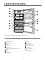
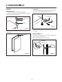
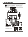
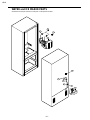
REFRIGERATOR
SERVICE MANUAL
CAUTION
BEFORE SERVICING THE PRODUCT,
READ THE SAFETY PRECAUTIONS IN THIS MANUAL.
MODELS:
LBC20514TT
CONTENTS
Safety Precautions………………………………………………................................ 2
1- Specifications…………………………………………………................................ 3
2- Parts Identifications …………………………………………................................ 4
3- Disassembly……………………………………………………............................... 5
Door……………………………………………………………................................... 5
Door Switch……………………………………………………...................................5
Fan and Fan Motor……………………………………………..................................6
Defrost Control Assembly ……………………………………..................................6
Lamp……………………………………………………………..................................6
Refrigerator Control Box……………………………………….................................6
Multi Duct……………………………………………………….................................. 6
4- Ajustment…………………………………………………….................................... 7
Compressor…………………………………………………….................................. 7
PTC-Starter…………………………………………………….................................. 7
OLP (Overload Protector)…………………………………….................................. 8
To Remove the Cover PTC………………………………….................................. 8
5- Circuit Diagram……………………………………………..................................... 9
6- Troubleshooting……………………………………...................................……….10
Compressor and Electric Components…………………....................................…10
PTC and OLP …………………………………………....................................…….11
Other Electrical Components………………………….....................................……12
Service Diagnosis Chart……………………………....................................………13
Refrigeration Cycle…….………………………………....................................……14
7- Operation Principle and Repair Method of Ice Maker….................................16
8- Description of Function and Circuit of MICOM……….............................……19
11- Refrigerator Exploded View …....................................................................... 38
SAFETY PRECAUTIONS
Pleasereadthefollowinginstructionsbeforeservicingyour
refrigerator.
1.Checktherefrigeratorforcurrentleakage.
2.Topreventelectricshock,unplugbeforeservicing.
3.Alwayschecklinevoltageandamperage.
4.Usestandardelectricalcomponents.
5.Don'ttouchmetalproductsinthefreezerwithwet
hands.Thismaycausefrostbite.
6.Preventwaterfromspilingontoelectricelementsorthe
machineparts.
7.Beforetiltingtherefrigerator,removeallmaterialsfrom
onorintherefrigerator .
8.Whenservicingtheevaporato,rwearglovestoprevent
injuriesfromthesharpevaporatorfins.
9.Serviceontherefrigeratorshouldbeperformedbya
qualifiedtechnician.Sealedsystemrepairmustbe
performedbyaCFCcertifiedtechnician.
-2-
1. SPECIFICATIONS
Models
Color
Capacity
Dimensions (in)
Refrigerant
Climate Class
Control Type
Rating
Case Material
Specification
Door Material
Reversible Door
Lamp (F)
Lamp ( R )
Basket (F)
Basket ( R )
Shelf (F)
Shelf ( R )
Cover, TV
Drawer
Vegetable
Tray Meat
Multi Flow
LBC20514TT
Titanium
20cuft
29.8 (W) x 32.2 (D) x 67.9 (H)
R134A (4.2oz)
Temperate(N)
F-control
115/60
EMBO(Normal)
VCM
Yes
1 (40W/Blue)
2 (40W/Blue)
1 (plastic)
2 (1/3)
2 (2/3)
1 full
1 Wire
4 fix
Humidity Control
Wire (lower)
Yes
Yes
Yes
-3-
2. PARTS IDENTIFICATIONS
PARTSANDFEATURES
A
B
I
C
J
D
K
E
L
F
M
G
H
N
Use this section to become more familiar with the parts and features.
NOTE:This guide covers several different models.The refrigerator you have purchased may have some
or all of the items listed below.The locations of the features shown below may not match your model.
A Digital Sensor Control
I Dairy Bin
B Refrigerator Light
J Design-A-Door
C Shelves
K Wire Freezer Shelf
D Snack Pan
L Refrigerator Door Rack
E Optibin Crisper
Keeps fruits and vegetable fresh and crisp
M Freezer Light
N Freezer Door Rack
F Ice Tray*
*on some models
G Ice Bin
H Wire Durabase
-4-
3. DISASSEMBLY
3-1 DOOR
Refrigerator Door
1. Remove the hinge cover by pulling it upwards.
2. Loosen the hexagonal bolts attaching the upper hinge to
the body and lift the freezer door.
Freezer Door
1. Loosen the hexagonal bolts attaching the lower hinge to
the body to remove the refrigerator door only.
LOWER HINGE
HINGE COVER
BOLT
BOLT
HINGE
Figure 3
Figure 1
3. Pull out the door gasket to remove from the door foam
assembly.
2. Pull out the door gasket to remove from the door foam
assembly.
3-2 DOOR SWITCH
GASKET
1. To remove the door switch, pry it out with a slotted-type
driver, as shown in (Figure 4).
2. Disconnect the lead wire from the switch.
LEAD WIRE
DOOR SWITCH
Figure 4
Figure 2
-5-
3-3 FAN AND FAN MOTOR
1. Remove the freezer shelf. (If your refrigerator has an
icemaker, remove the icemaker first)
2. Remove the grille by pulling it out and by loosening a
screw.
3. Remove the Fan Motor assembly by loosening 2 screws
and disassemble the shroud.
4. Pull out the fan and separate the Fan Motor and Bracket.
5. Pull out the fan and separate the Fan Motor and Bracket.
3-5-1 Refrigerator Compartment Lamp
1. Unplug the power cord from the outlet.
2. Remove refrigerator shelves.
3. Release the hooks on both ends of the lamp shield and
pull the shield downward to remove it.
4. Turn the lamp counterclockwise.
5. Assemble in reverse order of disassembly. Replacement
bulb must be the same specification as the original
(Max. 60 W-2EA).
FAN MOTOR
BRACKET
MOTOR
Figure 9
FAN
3-5-2 Freezer Compartment Lamp
Figure 11
GRILLE
3-6 CONTROL BOX-REFRIGERATOR
3-4 DEFROST CONTROL ASSEMBLY
Defrost Control assembly consists of Defrost Sensor and
FUSE–M.
The Defrost Sensor works to defrost automatically. It is
attached to the metal side of the Evaporator and senses its
Temperature.
Fuse-M is a safety device for preventing over-heating of
the Heater when defrosting.
At 72°C, it turns the Defrost Heater off.
1. Pull out the grille assembly. (Figure 6)
2. Separate the connector with the Defrost Control
assembly and replace the Defrost Control assembly
after cutting the Tie Wrap. (Figure 7)
GRILLE ASSEMBLY
1. Unplug refrigerator or disconnect power.
2. Reach behind light shield to remove bulb.
3. Replace bulb with a 60-watt appliance bulb.
4. Plug in refrigerator or reconnect power.
DEFROST-CONTROL
ASSEMBLY
1. First, remove all shelves in the refrigerator, than remove
the Refrigerator control Box by loosening 2 screws.
CONTROL BOX
COVER LAMP
Figure 10
2. Remove the Refrigerator Control Box by pulling it
downward.
3. Disconnect the lead wire on the right position and
separate the lamp sockets.
3-7 MULTI DUCT
Figure 6
Figure 7
3-5 LAMP
1. Remove an upper and
lower Cap by using a flat
screwdriver, and loosen 3
screws. (Figure 11)
2. Disconnect the lead wire
on the bottom position.
Figure 11
Figure 8
-6-
4. ADJUSTMENT
4-1 COMPRESSOR
4-1-1 Role
4-2-3 PTC-Applied Circuit Diagram
Starting Method for the Motor
The compressor intakes low temperature and low pressure
gas from the evaporator of the refrigerator and compresses
this gas to high-temperature and high-pressure gas. It then
delivers the gas to the condenser.
OVERLOAD PROTECTOR
N
4-1-2 Composition
The compressor includes overload protection. The PTC
starter and OLP (overload protector) are attached to the
outside of the compressor. Since the compressor is
manufactured to tolerances of 1 micron and is hermetically
sealed in a dust and moisture-free environment, use
extreme caution when repairing it.
4-1-3 Note for Usage
(1) Be careful not to allow over-voltage and over-current.
(2) If compressor is dropped or handled carelessly, poor
operation and noise may result.
(3) Use proper electric components appropriate to the
Particular Compressor in your product.
(4) Keep Compressor dry.
If the Compressor gets wet (in the rain or a damp
environment) and rust forms in the pin of the Hermetic
Terminal, poor operation and contact may result.
(5) When replacing the Compressor, be careful that dust,
humidity, and soldering flux don’t contaminate the inside
of the compressor. Dust, humidity, and solder flux
contaminate the cylinder and may cause noise,
improper operation or even cause it to lock up.
4-2 PTC-STARTER
4-2-1 Composition of PTC-Starter
(1) PTC (Positive Temperature Coefficient) is a no-contact
semiconductor starting device which uses ceramic
material consisting of BaTiO3.
(2) The higher the temperature is, the higher the resistance
value. These features are used as a starting device for
the Motor.
4-2-2 Role of PTC-Starter
(1) The PTC is attached to the Sealed Compressor and is
used for starting the Motor.
(2) The compressor is a single-phase induction motor.
Durign the starting operation, the PTC allows current
flow to both the start winding and main winding.
C
2
PTC
5
S
L1
3
6
PTC STARTER
Resistance Starter Capacitor Running
COMPRESSOR
MOTOR
M
M
S
SEALED
TERMINAL
Figure 12
4-2-4 Motor Restarting and PTC Cooling
(1) It requires approximately 5 minutes for the pressure to
equalize before the compressor can restart.
(2) The PTC device generates heat during operation.
Therefore, it must be allowed to cool before the
compressor can restart.
4-2-5 Relation of PTC-Starter and OLP
(1) If the compressor attempts to restart before the PTC
device is cooled, the PTC device will allow current to
flow only to the main winding.
(2) The OLP will open because of the over current
condition. This same process will continue (3 to 5
times) when the compressor attempts to restart until
the PTC device has cooled. The correct OLP must be
properly attached to prevent damage to the
compressor.
Parts may appear physically identical but could have
different electrical ratings. Replace parts by part
number and model number. Using an incorrect part
could result in damage to the product, fire, injury, or
possibly death.
4-2-6 Note for Using the PTC-Starter
(1) Be careful not to allow over-voltage and over-current.
(2) Do not drop or handle carelessly.
(3) Keep away from any liquid.
If liquid such as oil or water enters the PTC,
PTC materials may fail due to breakdown of their
insulating capabilities.
(4) If the exterior of the PTC is damaged, the resistance
value may be altered. This can cause damage to the
compressor and result in a no-start or hard-to-start
condition.
(5) Always use the PTC designed for the compressor and
make sure it is properly attached to the compressor.
Parts may appear physically identical but could have
different electrical ratings. Replace parts by part
number and model number. Using an incorrect part
could result in damage to the product, fire, injury, or
possibly death.
-7-
4-3 OLP (OVERLOAD PROTECTOR)
4-4 TO REMOVE THE COVER PTC
4-3-1 Definition of OLP
(1) OLP (OVERLOAD PROTECTOR) is attached to the
Compressor and protects the Motor by opening the
circuit to the Motor if the temperature rises and
activating the bimetal spring in the OLP.
(2) When high current flows to the Compressor motor, the
Bimetal works by heating the heater inside the OLP,
and the OLP protects the Motor by cutting off the
current flowing to the Compressor Motor.
4-3-2 Role of the OLP
(1) The OLP is attached to the Sealed Compressor used
for the Refrigerator. It prevents the Motor Coil from
being started in the Compressor.
(2) For normal operation of the OLP, do not turn the Adjust
Screw of the OLP in any way.
1) Remove the Cover Back M/C.
(2) Remove the screw on Cover PTC.
(OVERLOAD PROTECTOR cross section)
12345678
330 FBYY
Electrical
characteristics
part number
-S1 BOX98
Customer part
number
Lot code/
date code
Physical
termination
part number
Part
No.
Name
Base, phenolic
(UL 94 V-0 rated)
Movable arm support, plated steel
Stationary contact support,
plated steel
Heater support, plated steel
Heater, resistance alloy
Disc, thermostatic alloy
Movable arm, spring temper
copper alloy
Contact, movable, silver on copper
Contact, stationary, silver on copper
Slug, plated steel
Cover, polyester
(UL 94 V-0 rated)
Pin connector, plated copper alloy
(To engage 2.33/2.66 mm dia. pin)
Quick-connect terminal, brass,
conforms to UL 310, MEMA
DC-2, DIN 46344
Figure 13
1
(3) Remove two Housings on upper part of Cover PTC.
(4) Take out the cover PTC from upper to lower position
like ( 1 ).
2
(5) Turn 45¡ in the direction of (2)and take it out.
(6) Assembly in reverse order of disassembly.
-8-
5. CIRCUIT DIAGRAM
PWB(PCB) ASSEMBLY,DISPLAY
BO
BL
/WH
SB PR BK PK WH YL
STEPPING
MOTOR
F-FAN
PERCEPTION S/W
1 2 3 4 5 6 7 8 9
WH
/RD
R-DOOR
CON101
C D
WH
/RD
PR GY WH BL BK YL RD
BO
BL
/WH
SB
PR BK PK WH
1 2 3 4 5 6 7 8 9 10 11 12 13
1 2
CON4
YL GY GY
3 4 5 6 7 8 9 10 11 12
CON5
PWB(PCB) ASSEMBLY, MAIN
CON6
L1
11 10 9 8 7 6 5 4 3 2 1
BL
YL
BL
BK
SB BN
POWER
SUPPLY
CORD
1
2
3
4
5
6
7
8
PK
PK
BO
BO
A
F-DOOR
B
PERCEPTION S/W
DEF-SENSOR
WH
R-SENSOR
WH
BL
F-SENSOR
BL
7 6 5 4 3 2 1
RD
SB
BN
CON1
CON2
SB
YL
BN
BL
BL
BK
BN
RD
SB
N
Cs
4
S
5
GN
/YL
1 RD
CON6
2 BL
1 BK
CON1
2 BK
1 WH
CON2
1 WH
CON3
1 WH
2 WH
1 WH
CON4
CON5
M
3
BL
PWB (PCB) ASSEMBLY, ICE MAKER
6
(GN)
PTC STARTER
BL
BL
com
com
nc
nc
com
DOOR S/W-R
com
BO
PR
R-LAMPS
2
RD
C D
A B
F-LAMP
M
RD
C-FAN
I/MAKER
W/VALVE
V
OLP
PK
nc
FUSE-M
(72 C)
(98 C)
BK FUSE-M
CAPACITOR PART
Cr
POWER
S/W
M
ICE MAKER
MOTOR
HEATER,
SHEATH
ICE SENSOR
GN/YL
(GN)
nc
BK
BK
ICE MAKER PART
HEATER,SHEATH
GN/YL
(GN)
DOOR S/W-F
L
BL
BL
COMP' EARTH
PART
COMP' ACCESSORIES
* ALTERNATIVE COMP' ACCESSORIES
* P.T.C START OPTION
MC,MQ COMP'
Cr
BL
OLP
*PLUG TYPE, ICE MAKER PART, CAPACITOR PART,
P.T.C START OPTION, COMP' EARTH PART AND COMP'
ACCESSORIES ON CIRCUIT DIAGRAM ARE SUBJECT
TO CHANGE IN DIFFERENT LOCALITIES AND MODEL TYPE.
BK
N
EG COMP'
3
2
L
4
5
4
6
3
6
2
5
PTC
COMBO KIT(PTC+OLP)
BK:BLACK
YL:YELLOW
WH:WHITE
PK:PINK
BN:BROWN
GN:GREEN
BO:BRIGHT ORANGE
PR:PURPLE
-9-
MEZ48108403
SB:SKY BLUE
GY:GREY
RD:RED
BL:BLUE
6. TROUBLESHOOTING
6-1 COMPRESSOR AND ELECTRIC COMPONENTS
1
Power Source.
YES
Remove PTC-Starter
from compressor and
measure voltage
between Terminal C of
compressor and
terminal 5 or 6 of PTC.
(Rated voltage
±10%)?
No voltage.
OLP disconnected?
2
YES
Replace OLP.
NO
5
Check connection
condition.
Reconnect.
Applied voltage isn't
in acceptable range.
(115V ±10%)
2
Check
Check resistance
resistance
of
of motor
motor
compressor.
compressor.
.
Advise customer that
power supply needs to be
checked by an electrician.
5
The range of resistance is between 1~50 ? (ok)
Check the resistance
between M-C, S-C and
Replace
M-S in motor compressor. Open or short compressor
3
Check
resistance of
PTC-Starter.
Check resistance of
two terminals in
PTC-Starter.
Refer to Page 12.
4
Check OLP.
Check resistance of two
terminals in OLP.
Refer to Page 12.
5
Check
starting state.
Check the power supply
under load.
(Compressor attempting
to re-start after being off
for 5 minutes).
Supply
voltage rating
with ±10%.
YES
3
Did
compressor
start?
4
YES
NO
NO
- 10 -
3
5
Compressor
is OK
Replace the
compressor
1
6-2 PTC AND OLP
Separate PTC-Starter
from Compressor and
measure resistance
between No. 5 and 6
of PTC-Starter with a
Tester.
(Figure 19)
Observation value is
115V/60Hz : 6.8 ? ±30%
The resistance value
is 0 ? (short) or
8(open).
Separate OLP from
compressor and check
resistance value between
two terminals of OLP whit a
tester.
(Figure 20)
Shows continuity
Open
Check another
electric component.
Replace OLP.
5
6
Normal operation of
compressor is impossible
or poor.
?
Figure 19
- 11 -
Figure 20
Replace PTCStarter.
6-3 OTHER ELECTRICAL COMPONENTS
Not cooling at all
Compressor
doesn't run.
Check for open short or
incorrect resistance readings
in the following components
Cause
a. Starting devices
Short, open, or broken.
b. OLP
Poor contact
or shorted.
c. Compressor coil
Coil open or shorted.
d.Wiring harness
Poor contact
or shorted.
Replace
indicated component.
Poor cooling performance
Compressor runs
poorly.
Check starting
voltage.
Low voltage.
Advise customer that
the power supply
needs to be checked
by an electrician.
Fan motor
doesn't run.
Check voltage at
starting devices.
Poor or broken or
open contact.
Check current flowing
in sub-coil of
Compressor.
Shorted.
Check rating of OLP.
Lack of capacity.
Check wiring circuit.
Wire is open or
shorted.
Replace
indicated component.
Coil is shorted
or open.
Check Fan Motor.
Heavy frost buildup on
evaporator
Replace
indicated component.
Check current flow in
the following
components:
Sensor
Fuse-M
Check current flow in
the defrost heater.
- 12 -
Open.
Replace
indicated component.
Open.
Replace
defrost heater.
6-4 SERVICE DIAGNOSIS CHART
COMPLAINT
POINTS TO BE CHECKED
REMEDY
No Cooling.
• Is the power cord unplugged from the outlet?
• Check if the power switch is set to OFF.
• Check if the fuse of the power switch is shorted.
• Measure the voltage of the power outlet.
• Plug into the outlet.
• Set the switch to ON.
• Replace the fuse.
• If the voltage is low, correct the wiring.
Cools poorly.
• Check if the unit is placed too close to the wall.
• Check if the unit is placed too close to the stove,
gas cooker, or in direct sunlight.
• Is the ambient temperature too high or
the room door closed?
• Check if food put in the refrigerator is hot.
• Did you open the door of the unit too often
or check if the door is sealed properly?
• Check if the Control is set to Warm position.
• Place the unit about 4 inches (10 cm) from the wall.
• Place the unit away from these heat sources.
• Is food placed in the cooling air outlet?
• Check if the control is set to colder position.
• Is the ambient temperature below 41°F(5° C)?
• Place foods in the high-temperature section.
(front part)
• Set the control to Recommended position.
• Set the control to Warm position.
Condensartion or ice
forms inside
the unit.
• Is liquid food sealed?
• Check if food put in the refrigerator is hot.
• Did you open the door of the unit too
often or check if the door is sealed properly?
• Seal liquid foods with wrap.
• Put in foods after they have cooled down.
• Don't open the door too often and close
it firmly.
Condensartion forms
in the Exterior Case.
• Check if the ambient temperature and humidity
of the surrounding air are high.
• Is there a gap in the door gasket?
• Wipe moisture with a dry cloth. It will disappear
in low temperature and humidity.
• Fill up the gap.
There is abnormal
noise.
• Is the unit positioned in a firm and even place?
• Adjust the Leveling Screw, and position the
refrigerator in a firm place.
• Remove the objects.
Foods in the
Refrigerator
are frozen.
Door does not
close well.
• Are any unnecessary objects placed
in the back side of the unit?
• Check if the Tray Drip is not firmly fixed.
• Check if the cover of the compressor enclosure
in the front lower side is taken out.
• Check if the door gasket is dirty with
an item like juice.
• Is the refrigerator level?
• Put in foods after they have cooled down.
• Don't open the door too often and close
it firmly.
• Set the control to Recommended position.
• Fix the Tray Drip firmly in the original position.
• Place the cover in its original position.
• Clean the door gasket.
• Is there too much food in the refrigerator?
Ice and foods
smell unpleasant.
• Lower the ambient temperature.
• Check if the inside of the unit is dirty.
• Are foods with a strong odor unwrapped?
• The unit smells of plastic.
• Position in the firm place and level the
Leveling Screw.
• Make sure food stored in shelves does not prevent
the door from closing.
• Clean the inside of the unit.
• Wrap foods that have a strong odor.
• New products smell of plastic, but this
will go away after 1-2 weeks.
Other possible problems:
Check if frost forms in
the freezer.
Not
defrosting
Check Components
of the defrosting
circuit.
Check the
refrigeration system.
The system
is faulty.
Perform sealed
system repair.
Check the
Thermistor.
The operation of
the Thermistor is
incorrect.
- 13 -
Replace the
Thermistor.
6-5 REFRIGERATION CYCLE
* Troubleshooting Chart
CAUSE
STATE OF
THE UNIT
STATE OF THE
EVAPORATOR
TEMPERATURE
OF THE
COMPRESSOR
REMARKS
A little higher than
ambient
temperature.
- Refrigerant level is low due to a
leak.
¥
- Normal cooling is possible by
restoring
the normal amount of
¥
refrigerant
and repairing the leak.
¥
Equal to ambient
temperature.
- No discharging of refrigerant.
- Normal cooling is possible by
restoring
the normal amount of
¥
refrigerant and repairing the leak.
¥
A little higher than
ambient
temperature.
- Normal discharging of the
refrigerant.
¥
- The capillary tube is faulty.
Freezer
compartment and
refrigerator don’t
cool normally
Low flowing sound of
refrigerant is heard and frost
forms in inlet only.
COMPLETE
LEAKAGE
Freezer
compartment and
refrigerator don’t
cool normally
Flowing sound of refrigerant
is not heard and frost isn’t
formed.
PARTIAL
CLOG
Freezer
compartment and
refrigerator don’t
cool normally
Flowing sound of refrigerant
is heard and frost forms in
inlet only.
WHOLE
CLOG
Freezer
compartment and
refrigerator don’t
cool.
Flowing sound of refrigerant is Equal to ambient
not heard and frost isn’t
temperature.
formed.
MOISTURE
CLOG
Cooling operation
stops periodically.
Flowing sound of refrigerant is Lower than ambient - Cooling operation restarts when
heating
the inlet of the capillary
¥
not heard and frost melts.
temperature.
tube.
¥
PARTIAL
LEAKAGE
LEAKAGE
CLOGGEDBYDUST
DEFECTIVE
COMPRESSION
Alittle higher than
ambient
temperature.
COMPRE- Freezer and
refrigerator don’t
SSION
Low flowing sound of
refrigerant is heard and frost
forms in inlet only.
NO
COMPRESSION
Flowing sound of refrigernat is Equal to ambient
temperature
not heard and there is no
frost.
cool.
No compressing
operation.
- 14 -
- Normal discharging of the
refrigerant.
¥
- Low pressure at high side of
compressor
due to low
¥
refrigerant
level.
¥
- Nopressure in the high pressure
part
¥ of the compressor.
¥
6-5-1 SEALED SYSTEM DIAGNOSIS
Not Cooling Complaint
All components operating, No airflow problems, Not frosted up as a defrost problem
problem has been isolated to sealed system area
Frost
Pattern?
Partial
None
Equalization
Test
Equalization
Test
Very Fast
Very Slow
Very Slow
Very Fast
Fast
Inefficient
Compressor
Partial
Restriction
Complete
Restriction
Condenser
Temperature
Cap Tube
Sound
Hotter than Normal
Faint
Room Temperature
None to Weak
Air/Low Side
Leak
Loss of Change
Compressor Not
Pumping
Trace of Oil
Yes
No
Leak
Undercharge
(The equalization test is trying to restart a compressor after it has been operating.)
- 15 -
7. OPERATION PRINCIPLE AND REPAIR METHOD OF ICE MAKER
7-1 OPERATION PRINCIPLE
7-1-1 Operation Principle of Ice Maker
Power On
Start Position
Icemaking
Mode
Harvest
Mode
Fill
Park Position
Test Mode
Adjusts Ejector to Start Position with power on.
• Waits until water becomes cold after starting the
Icemaking operation.
• Runs MOTOR to drop ice from the tray into the ICE BIN.
• Performs Icemaking Mode after supplying water by operating
the SOLENOID in ICE VALVE.
• With the detect lever, checks if the ICE BIN is full.
• To operate LINE and SERVICE, press and hold the Cube Size button
for 3 seconds. The icemaking will run through 3 stages:
Harvest
Fill
Icemaking.
1. Turning the Icemaker stop switch off (O) stops the icemaking function.
2. Setting the Icemaker switch to OFF and then turning it back on will reset the icemaker control.
Cube Size button
Power (On/Off) Switch
- 16 -
7-2 ICE MAKER FUNCTIONS
7-2-1 Ice Making Mode
1. Icemaking refers to the freezing of supplied water in the ice trays. Complete freezing is assured by measuring the
temperature of the Tray with icemaking SENSOR.
2. Icemaking starts after completion of the water fill operation.
3. The icemaking function is completed when the sensor reaches -7°C, 60 to 240 minutes after starting.
NOTE : After icemaker power is ON, the icemaker heater will be on for test for 9 sec.
7-2-2 Harvest Mode
1. Harvest (Ice removing) refers to the operation of dropping ices into the ice bin from the tray when icemaking has
completed.
2. Harvest mode:
(1) The Heater is ON for 30 seconds, then the motor starts.
(2) Harvest mode is completed if it reaches start position again while Heater & Motor are on at the same time.
A. ice bin is full : The EJECTOR stops (heater off).
B. ice bin is not full : The EJECTOR rotates twice to open for ice.
NOTE : If the EJECTOR does not rotate once within 5 minutes in status (2), separate heater control mode starts
operating to prevent the EJECTOR from being constrained. (It is recommended that the user open for ice to
return to normal mode.)
7-2-3 Fill/Park Position
1. Once a normal harvest mode has been completed, the water solenoid will be activated.
2. The amount of water is adjusted by pressing the fill key repeatedly. This changes the time allowed for fill as illustrated in
the table below.
Water supply amount table
STAGE
TIME TO SUPPLY
1
6 sec.
INDICATIONS
REMARKS
The water amount will vary depending
2
on the water control switch setting, as
7 sec.
well as the water pressure of the
connected water line.
3
8 sec.
- 17 -
7-2-5 Function TEST
1. This is a compulsory operation for test, service, cleaning, etc. It is operated by pressing and holding the Cube Size button for 3 seconds
2. The test works only in the Icemaking Mode. It cannot be entered from the Harvest or Fill mode. (If there is an ERROR, it
can only be checked in the TEST mode.)
3. Caution! If the test is performed before water in the icemaker is frozen, the ejector will pass through the water. When the fill
mode begins (Stage 4), unless the water supply has been shut off, added water will overflow into the ice bin. If the control
Doesn’t operate normally in the TEST mode, check and repair as needed.
4. After water is supplied, the normal CYCLE is followed: icemaking
Harvest
Fill
Park Position.
5. Five seconds after Stage 5 is completed, the icemaker returns to MICOM control. The time needed to supply water
resets to the pre- test setting.
Diagnosis TABLE
STAGE
ITEMS
1
HEATER
2
MOTOR
3
HALL IC
INDICATOR
*
REMARKS
Five seconds after heater starts, heater will
go off if temperature recorded by sensor is
10°C (50°F)or lever is in up position.
Five seconds after heater starts, you can
confirm that motor is moving.
You can confirm Hall IC detection of position.
(TRAY)
4
SOLENOID VALVE
5
HALL IC
(LEVER)
6
Reset
Two seconds after detection of initial
position, you can confirm that valve is on.
You can check when the Hall IC is sensing a full
ice condition. (If there is a water fill error, the
fifth LED is not on.)
Five seconds after fifth stage is completed,
the icemaker resets to initial status.
Return to Status prior to
TEST MODE
7-3 DEFECT DIAGNOSIS FUNCTION
7-3-1 ERROR CODES shown on Ice Maker water supply control panel
*
NO
DIVISION
1
Normal
2
Icemaking
Sensor
malfunction
3
Icemaker Kit
malfunction
PROBLEM
INDICATOR
Note fill times
(see previous page)
None
Open or shorted wire or sensor
Ejector blades have not reached
the park position after 18
minutes from start of harvest
mode
ERROR indicators in table can be checked only in TEST mode.
- 18 -
REMARKS
Display switch
operates properly
Make sure that the wire
on each sensor is
connected.
Check
HALL IC/MOTOR/
HEATER/RELAY
8. DESCRIPTION OF FUNCTION & CIRCUIT OF MICOM
8-1 FUNCTION
8-1-1 Function
1. When the appliance is plugged in, it is set to "4" for Refrigerator and "4" for freezer.
You can adjust the Refrigerator and the Freezer control temperature by pressing the ADJUST button.
2. When the power is initially applied or restored after a power failure, it is automatically set to "4" & "4".
8-1-2 Control of freezer fan motor
1. Freezer fan motor has high and standard RPMs.
2. High RPM is used when electricity is first on, for ICE PLUS , and when refrigerator is overloaded.
But standard RPM is used for general purposes.
3. To improve cooling speed and load corresponding speed, the RPM of freezer fan motor shall change from normal speed
to hign speed.
4. High speed (2500RPM) : Initial power on or load corresponding operation, ICE PLUS.
Normal speed ( 2200 RPM): general working conditions.
5. Fan motor stops when refrigerator of freezer door opens.
8-1-3 ICE PLUS
1. The purpose of this function is to intensify the cooling speed of freezer and to increase the amount of ice.
2. Whenever selection switch is pressed, selection/release, the LED will turn ON or OFF.
3. If there is a power cut and the refrigerator is power on again, ICE PLUS function will be canceled.
4.To activate these function you need to press the ICE PLUS key and the LED will turn ON. This function will remain
activated for 24 hrs. The first three hours the compressor and ICE PLUS will be ON. The next 21hours the freezer will
be controlled at the lowest temperature. After 24 hours or if the ICE PLUS key is pressed again, the freezer will
return to its previous temperature.
5. For the first three hours notice the following cases:
(1) Compressor and freezer fan(HIGH RPM) continuously operate for three hours.
(2) If defrost starts during ICE PLUS, ICE PLUS operates for the rest of time after defrost is
completed, when ICE PLUS operation time is less than 90 minutes.
If ICE PLUS operates for more than 90minutes, the ICE PLUS will operate for two hours after
defrost is completed.
(3) If ICE PLUS is pressed during defrost, ICE PLUS LED is on but this function will start seven
minutes after defrost is completed and it shall operate for three hours.
(4) If ICE PLUS is selected within seven minutes after compressor has stopped, the compressor (compressor
delays seven minutes) shall start after the balance of the delay time.
(5) The fan motor in the freezer compartment rotates at high speed during ICE PLUS.
6. For the rest of 21 hours, the freezer will be controlled at the lowest temperature.
8-1-4. REFRIGERATOR LAMP AUTO OFF
1. To protect the risk of lamp heat, when Refrigerator door opens for 7 min., refrigerator lamp is auto off.
- 19 -
8-1-5 Alarm for Open Door
1. This feature sounds a buzzer when the freezer or refrigerator door is not closed within 1 minute after it is opened.
2. One minute after the door is opened, the buzzer sounds three times each for 1/2 seconds. These tones repeat every 30
seconds.
3. The alarm is cancelled when the freezer or the refrigerator is closed while the buzzer sounds.
Freezer Door Closed
or Refrigerator
Door
Open
Closed
Closed
Open
3 Times
3 Times
3 Times
3 Times
Buzzer
Within 1 min.
1 min.
30 sec
30 sec
30 sec
8-1-6 Buzzer Sound
When the button on the front Display is pushed, a Ding~ Dong~ sound is produced.
(Refer to the Buzzer Circuit 8-2-4 No. 3)
8-1-7 Defrosting (removing frost)
1. Defrosting starts each time the COMPRESSOR running time reaches 7 hours.
2. For initial power on or for restoring power, defrosting starts when the compressor running time reaches 4 hours.
3. Defrosting stops if the sensor temperature reaches 46.4°F(8° C) or more. If the sensor doesn’t reach 46.4°F(8° C) in
2 hours, the defrost mode is malfunctioning. (Refer to the defect diagnosis function, 8-1-9.)
4. Defrosting won’t function if its sensor is defective (wires are cut or short circuited)
8-1-8 Electrical Parts Are Turned On Sequentially
Electrical parts such as COMP, defrosting heater, freezer FAN, etc. are turned on in the following order to prevent noise and
parts damage. Several parts are started at the same time at initial power on and are turned off together when TEST is
completed.
OPERATING
Initial power on
Temperature of Defrosting
Sensor is 45°C or more
(when unit is newly
purchased or when moved)
Temperature of defrosting
sensor is lower than 45°C
(when power cuts, SERVICE)
ORDERS
POWER in 1/2 second COMP
ON
ON
POWER
ON
in 1/2 second
in 1/2 second
Reset to normal operation
from TEST MODE
Total load
OFF
COMP
ON
in 7 minute
- 20 -
in 1/2 second
Freezer FAN
ON
Defrosting
heater ON
in 10 second
in 1/2 second
Freezer FAN
ON
COMP
ON
in 1/2 second
Defrosting
heater OFF
Freezer FAN
ON
8-1-9 Defect Diagnosis Function
1. Automatic diagnosis makes servicing the refrigerator easy.
2. When a defect occurs, the buttons will not operate; but the tones. such as ding. will sound.
3. When the defect CODE removes the sign, it returns to normal operation (RESET).
4. The defect CODE shows on the Refrigerator and Freezer Display.
ERROR CODE on display panel
LED OFF LED ON
ERROR CODE
NO
ITEM
1
Failure of freezer
sensor
All off
Cut or short circuit wire
2
Failure of
Refrigerator sensor All off
Cut or short circuit wire
3
Failure of defrost
sensor
Cut or short circuit wire
4
5
Poor of defrost
CONTENTS
All off
2 hours later after
starting defrost, If
sensor doesn’t be
over 46ºF (8ºC)
All off
If there is no fan motor
signal, for more than
65 seg. in operation
fan motor.
Failure of BLDC fan All off
motor at freezing
compartment
- 21 -
REMARKS
Inspect Connecting
wires on each sensor
Snapping of defrost
heater or Temperature
fuse, pull-out of
Connector (indicated
minimum 2 Hours
after failure occurs)
Poor motor, hocking to
wires of fan, contact of
structures to fan,
snapping or short of lead
8-1-10 TEST Mode
1. The Test mode allows checking the PCB and the function of the product as well as finding out the defective part in case of
an error.
2. The test mode is operated by pressing two buttons at Display panel.
3. While in the test mode, the function control button is not recognized, but the recognition tone (beep~) sounds.
4. After exiting the test mode, be sure to reset by unplugging and then plugging in the appliance.
5. If an error, such as a sensor failure, is detected while in the test mode, the test mode is cleared and the error code is
displayed.
6. While an error code is displayed, the test mode will not be activated.
MODE
MANIPULATION
CONTENTS
REMARKS
TEST1
Push ULTRA ICE
key and ADJUST key of
Freezer Temperature at the
same time over 3
seconds.
1. Continuous operation of the
COMPRESSOR
2. Continuous operation of the freezer fan
3. STEPPING DAMPER OPEN
4. Defrosting Heater OFF
5. Every DISPLAY LED ON
TEST2
Push ULTRA ICE
key and ADJUST key of
Freezer Temperature at the
same time over 3 seconds
in TEST MODE 1
1. COMP OFF
2. Freezer FAN OFF
3. STEPPING DAMPER CLOSE
4. Defrosting heater ON
5. DISPLAY LED 1, 3, 5, 7 ON
Reset if the
temperature of the
Defrosting sensor is
46°F (8° C) or more.
Reset
Push ULTRA ICE
key and ADJUST key of
Freezer Temp. at the same
time over 3 seconds. in
TEST MODE 2
Reset to the previously setting before
TEST MODE
The compressor will
Start after a 7-minute
delay.
NOTE : LED CHECK MODE: When the refrigerator temperature control and the freezer temperature control button at the
same time are hold for 1 second or longer, every LED on the display turns on at the same time. when the button are
relesed, the previous mode is restored.
* Freezer Fan RPM Variable Check:
In case the freezer fan is in operation when the ADJUST key in Refrigerator and Freezer Temp. Control are pressed for
more than one second at the same time freezer fan RPM changes. (for example if high speed, to normal speed or if
normal speed, to high speed for 30 seconds)
After 30 seconds, it turns to its original RPM.
* Demonstration MODE:
1. When the ULTRA ICE key and ADJUST key of refrigerator temperature control are pressed for more than 3 seconds at the
same time temperature’s
.
it converts to demostration mode.
2. In this status, each LED is rotated with 1 second interval.
3. In this status, all Loads are off (Compressor / Fan / Damper / Heater)
(Even is Demonstration Mode, the refrigerator Lamp automatic off function works normally and can be demostrated)
4. It reset if you do again as clause.
- 22 -
8-2 PCB FUNCTION
8-2-1 Power Circuit
The secondary part of the TRANSFORMER is composed of the power supply for the display, the BLDC FAN Motor drive
(15.5 V), the relay drive (12 Vdc) and the MICOM and IC (5 Vdc).
The voltage for each part is as follows:
PART
VA 1
CE 3
CE 4
VOLTAGE
115 Vac
12 Vdc
15.5 Vdc
CE 5
5V
VA1 is a part for preventing over voltage and noise. When 385V or higher power is applied, the inside elements are shortcircuited and broken, resulting in blowout of the fuse in order to protect the elements of the secondary part of the
TRANSFORMER.
- 23 -
8-2-2 Oscillation Circuit
This circuit generates the base clock for calculating time and the synchro clock for transmitting data from and to the inside
logic elements of the IC1 (MICOM). Be sure to use specific replacement parts, since calculating time by the IC1 may be
changed. If changed, the OSC1 SPEC will not work.
8-2-3 Reset Circuit
The RESET circuit allows all the functions to start at the initial conditions by initializing various parts, including the RAM
inside the MICOM (IC1) when the power is initially supplied or the power supply to the MICOM is restored after a
momentary power failure. For the initial 10ms of power supply, LOW voltage is applied to the MICOM RESET terminal.
During a normal operation, 5V is applied to the RESET terminal. (If a malfunction occurs in the RESET IC, the MICOM will
not operate.)
- 24 -
8-2-4 Load / Buzzer Drive & Open Door Detection Circuit
1. Load Drive Condition Check
G5SB-14
FREEZER DOOR
SWITCH
REFRIGERATOR
DOOR SWITCH
LOAD TYPE
Measurement Location (IC6)
Condition
COMP
DEFROSTING
HEATER
LAMP
TCM
POWER MODE
(OPTIONAL)
NO.13
NO.14
NO.16
NO.12
ON
1V or below
OFF
12V
VALVE
(DISPENSER
MDL)
NO.15
2. Fan motor driving circuit (freezing compartment fan)
1. This circuit makes standby power 0 by cutting off power supplied to ISs inside of the fan motor in the fan motor OFF.
2. This is a circuit to perform a temporary change of speed for the fan motor and applies DC voltage up to 7.5V ~ 16V to motor.
3. This circuit prevents over-driving the fan motor by cutting off power applied to the fan motor in the lock of fan motor by
sensing the operation RPM of the fan motor.
a part
b part
MOTOR OFF
2V or less
0V
MOTOR ON
13V~15V
0V
- 25 -
c part
5V
2V~3V
3. Buzzer Drive Condition Check
Condition
Measurement Location
Tone (Ding~Dong~) when the button on
the display is pushed.
0.05 s
0.2 s
0.1 s
Alarm for open door
(beep-beep-beep)
2s
0.5 s
5V
5V
0V
0V
5V
5V
IC1 ( A )
0V
IC1 ( B )
2.63 kz (Ding~)
2.21 kz (Dong~)
OFF
0.5 s
0V
0V
2.63 kz(Beep~)
0V
OFF
4. Open Door Detection Circuit Check
FREEZER DOOR
SWITCH
REFRIGERATOR DOOR
SWITCH
Measurement
Location
Freezer/
Refrigerator Door
(PIN NO.63 & PIN NO.8)
Closed
5V
Open
0V
- 26 -
8-2-5 Temperature Sensor Circuit
FREEZER-SENSOR
REFRIGERATOR-SENSOR
DEFROST-SENSOR
The upper CIRCUIT reads REFRIGERATOR temperature, FREEZER Temperature, and DEFROST-SENSOR temperature
for defrosting and the indoor temperature for compensating for the surrounding temperature into MICOM.
OPENING or SHORT state of each TEMPERATURE SENSOR are as follows:
SENSOR
CHECK POINT
Freezer Sensor
POINT A Voltage
Refrigerator Sensor
POINT B Voltage
Defrosting Sensor
POINT C Voltage
NORMAL (-30°C ~ 50°C)
0.5 V ~ 4.5 V
8-2-6 Refrigeration Compartment Stepping Motor Damper Circuit
* The circuit shown below is the damper circuit to regulate the refrigerator temperature.
1
2
3
- 27 -
SHORT-CIRCUITED
0V
OPEN
5V
8-2-7 Temperature Compensation & Overcooling/Undercooling Compensation Circuit
1. Refrigerator Temperature Compensation
Refrigerator
Resistance
Temperature
(RCR)
Compensation
180 K
+2.5°C
56 K
+2.0°C
33 K
+1.5°C
18 K
+1.0°C
12 K
+0.5°C
Remark
Compensation by
raising the
temperature
10 K
0 °C
Standard Temperature
8.2 K
-0.5°C
5.6 K
-1.0°C
Compensation by
lowering the
temperature
3.3 K
-1.5°C
2K
-2.0°C
470
-2.5°C
Table of Temperature Compensation by adjusting the
resistance (difference from the current temperature)
e.g., If the refrigerator compensation resistance
(RCR) is changed from 10K (the current resistance)
to 18K (the adjustment resistance), the temperature
of the refrigerator rises 33.8°F(+1°C).
2. The temperature compensation for refrigerator compartment is in the following table:
Revised resistance
Present resistance
470
2k
3.3k
5.6k
8.2k
Refrigerator
(RCR)
10k
12k
18k
33k
56k
180k
470
No
change
0.5°C
Down
1°C
Down
1.5°C
Down
2°C
Down
2.5°C
Down
3°C
Down
3.5°C
Down
4°C
Down
4.5°C
Down
5°C
Down
2k
0.5°C
Up
No
Change
0.5 °C
Down
1°C
Down
1.5 °C
Down
2°C
Down
2.5 °C
Down
3°C
Down
3.5 °C
Down
4°C
Down
4.5 °C
Down
3.3k
1°C
Up
0.5°C
Up
No
Change
0.5°C
Down
1°C
Down
1.5°C
Down
2°C
Down
2.5°C
Down
3°C
Down
3.5°C
Down
4°C
Down
5.6k
1.5 °C
Up
1°C
Up
0.5°C
Up
No
Change
0.5 °
Down
1°C
Down
1.5 °C
Down
2°C
Down
2.5 °C
Down
3°C
Down
3.5 °C
Down
8.2k
2°C
Up
1.5°C
Up
1°C
Up
0.5°C
Up
No
Change
0.5°C
Down
1°C
Down
1.5°C
Down
2°C
Down
2.5°C
Down
3°C
Down
10k
2.5°C
Up
2°C
Up
1.5°C
Up
1°C
Up
0.5°C
Up
No
Change
0.5°C
Down
1°C
Down
1.5°C
Down
2°C
Down
2.5°C
Down
12k
3°C
Up
2.5 °C
Up
2°C
Up
1.5 °C
Up
1°C
Up
0.5°C
Up
No
Change
0.5 °C
Down
1°C
Down
1.5 °C
Down
2°C
Down
18k
3.5°C
Up
3°C
Up
2.5°C
Up
2°C
Up
1.5°C
Up
1°C
Up
0.5°C
Up
No
Change
0.5°C
Down
1°C
Down
1.5°C
Down
33k
4°C
Up
3.5 °C
Up
3°C
Up
2.5 °C
Up
2°C
Up
1.5 °C
Up
1°C
Up
0.5°C
Up
No
Change
0.5 °C
Down
1°C
Down
56k
180k
4.5°C
Up
4°C
Up
3.5°C
Up
3°C
Up
2.5°C
Up
2°C
Up
1.5°C
Up
1°C
Up
0.5°C
Up
No
Change
0.5°C
Down
5°C
Up
4.5°C
Up
4°C
Up
3.5°C
Up
3°C
Up
2.5°C
Up
2°C
Up
1.5°C
Up
1°C
Up
0.5°C
Up
No
Change
NOTE: This circuit is designed to input the necessary temperature compensation values into the MICOM. This adjusts the
refrigerator temperature, which is different in each model.
- 28 -
8-2-8 Key Button Input & Display Light-On Circuit
The circuit shown above determines whether a function control key on the operation display is pushed. It also turns on the
corresponding function indication LED DISPLAY. The drive type is the scan type.
150J
- 29 -
8-3 RESISTANCE SPECIFICATION OF SENSOR
TEMPERATURE DETECTED
BY SENSOR
RESISTANCE OF FREEZER
SENSOR
RESISTANCE OF REFRIGERATOR &
DEFROST SENSOR & ROOM SENSOR
- 20° C
22.3 K ?
77 K ?
- 15° C
16.9 K ?
60 K ?
- 10° C
13.0 K ?
47.3 K ?
- 5° C
10.1 K ?
38.4 K ?
0° C
7.8 K ?
30 K ?
+ 5 °C
6.2 K ?
24.1 K ?
+ 10° C
4.9 K ?
19.5 K ?
+ 15° C
3.9 K ?
15.9 K ?
+ 20° C
3.1 K ?
13 K ?
+ 25° C
2.5 K ?
11 K ?
+ 30° C
2.0 K ?
8.9 K ?
+ 40° C
1.4 K ?
6.2 K ?
+ 50° C
0.8 K ?
4.3 K ?
- The resistance of the SENSOR has a ±5% common difference.
- Measure the resistance of the SENSOR after leaving it for over 3 minutes in the measuring temperature.
This delay is necessary due to sensor response speed.
¥Measure the F-SENSOR, SUPER FROST SENSOR, R1, R2-SENSOR after disconnect CON5 of PWB ASSY, MAIN.
- 30 -
8-4 TROUBLESHOOTING
1. The whole DISPLAY
LED/SEVEN SEGMENT
DISPLAYis off.
2. DISPLAY LED/
SEVEN SEGMENT
DISPLAY operates
abnormally
INDICATED BY
POWER SOURCE
is poor.
NO COOLING.
PROBLEM
COOLING is poor.
FREEZER
TEMPERATURE is
incorrect
CHECK
1. FREEZER/
REFRIGERATOR.
2. If LAMP is dim.
3. The connection of
the MAIN PWB
CONNECTOR.
1. If the COMPRESSOR
operate.
2. If refrigerant is leaking.
.
1. If FANMOTOR
operates.
2. If DEFROSTING
is normal.
3. If SENSOR
is normal.
4. Door Line contact.
CHECKING METHOD
Check if FREEZER/
REFRIGERATOR DOOR IS
OPEN and check display.
Check visually.
Check connection of
CONNECTOR.
SOLUTION
Check outlet Voltage.
CAUSE
POWER SOURCE is poor.
Replace TRANS.
Use boosting TRANS.
Reconnect CONNECTOR.
Applied voltage error.
CONNECTOR connection
is poor.
TRANS FUSE is open.
Door liner damaged.
SENSOR RESISTANCE is
poor.
DEFROSTING is poor.
Replace door liner.
See DEFROSTING
is poor .
Replace SENSOR.
Certify the MOTOR and the
connection of the black wire
of the MAIN PWB
CONNECTOR (CON2).
USE TEST MODE1
COMPRESSOR locked or
Replace COMPRESSOR.
(forced COOLING).
blocked.
If less than 7 minutes pass
OLP, PTC is poor.
Replace OLP, PTC.
after compressor shuts off,
COMPRESSOR RELAY is
Replace MAIN PWB.
don’t press the KEY and
poor.
wait.
THE CONNECTING WIRE
Check the connection of the
is poor.
black wire of the MAIN PWB
CONNECTOR (CON2).
Measure the amount of frost
Refrigerant leakage.
Replace the leaking part and
sticking on EVAPORATOR
replace any lost refrigerant.
and the surface temperature
of the condenser pipe.
USE TEST MODE1
FAN MOTOR is poor.
Replace the FAN MOTOR.
(forced COOLING).
CONNECTING WIRE is poor.
Check the amount of frost
sticking on the
EVAPORATOR .
Check the resistance
of the Refrigerator
SENSOR.
Check the seal when
the door is closed.
- 31 -
PROBLEM
If REFRIGERATOR
INDICATED BY
CHECK
CHECKING METHOD
1.If FREEZER TEMPERATURE Check is FREEZER
CAUSE
SOLUTION
Make sure the
Replace FAN MOTOR.
DOOR isattached.
FAN MOTOR is poor.
Remove impurities.
Make sure that the amount
Passage of cool air
TEMPERATURE istoo low.
and speed of cool air are
is blocked.
isn ormal.
FAN MOTOR is
sufficient by touching the
See DEFROSTING is poor .
2. If amount of cool air from
sufficient.
EVA frozen.
Replace TEMPERATURE
FUSE.
Check EVAPORATOR
connection and wire of MAIN
PWB CONNECTOR.
Replace DEFROST-SENSOR.
Replace RY3 of MAIN PWB.
Remove ice and impurities.
Check HEATER PLATE
resistance.
Reassemble the
DEFROST-SENSOR.
Reassemble DOOR.
Replace GASKET.
Replace HEATER.
check supplied on the
HEATER disconnection.
Replace Door liner.
3. Door Line contact.
1. If HEATER emits heat.
Check DRAIN PIPE.
REFRIGERATOR.
Check door seal when
door is closed.
USE TEST MODE2
(forced DEFROSTING).
Door liner damaged.
TEMPERATURE
NO DEFROSTING.
is too low.
COOLING is poor.
DEFROSTING is
poor.
TEMPERATURE FUSE
disconnection.
Connection is poor.
2. If DRAIN PIPE is
blocked.
DEFROST-SENSOR is poor.
HEATER RELAY is poor.
DRAIN PIPE is blocked.
3. If ice remains after
DEFROSTING.
Make sure that DEFROST
Connection is poor.
SENSOR is connected.
Make sure that FREEZER /
DOOR does not close
REFRIGERATOR DOOR is closed. properly.
- 32 -
8-5 MAIN PWB ASSEMBLY AND PARTS LIST
8-5-1 Main PWB Assembly
- 33 -
8-5-2 Replacement Parts List
- 34 -
8-5-3 PWB Assembly, Dysplay and Parts List
- 35 -
8-6 PWB DIAGRAM
8-6-1 PWB Main Assembly
RY5
G5S-1A
- 36 -
- 37 -
#EV#
EXPPLODED VIEW
CASE PARTS
CAUTION: Use the part number to order part, not the position number.
103B
281A
B01
281B
103A
410A
409D
406B
501F
503G
503F
282E
503D
282F
903D
503C
610A
145A
503E
501A
409B
619B
120B
411A
304A
125D
158A
S38
282B
145B
S01
301A
B01
106B
128E
282H
903E
327A
283B
105A
283D
610A
128F
401A
318A 317A
412D
282C
106A
314A
284D
310A
307A
409B
308A
410G
319E
309A
405G
405F
418A
404A
323B
405C
106A
329A
420A
158E
312A
405A
329C
328A
319A
305B
305C
S22
332A
319C
315A
903B
105F
135C
903A
305C 305B
903B
103C
- 38 -
#EV#
FREEZER PARTS
CAUTION: Use the part number to order part, not the position number.
131A
149A
136C
- 39 -
#EV#
REFRIGERATOR PARTS
CAUTION: Use the part number to order part, not the position number.
143E
140D
140B
143E
140E
140D
140B
S24
S24
S24
143E
140D
140B
S24
140E
S24
143F
140E
142D
140B
S24
142E
128A
103E
103E
170A
128B
167B
154A
103E
151A
103E
155B
151A
- 40 -
151C
#EV#
DOOR PARTS
CAUTION: Use the part number to order part, not the position number.
230A
241A
233A
231A
241B
286A
212G
281E
241C
244E
241E
244A
212J
286A
241D
243A
S27
205D
200A
203A
201A
212J
281E
212A
286A
243A
283F
S27
- 41 -
#EV#
WATER and ICE MAKER PARTS
CAUTION: Use the part number to order part, not the position number.
S28
602A
600C
600A
622B
618A
627A
616E
623C
S29
619C
S31
619A
262D
- 42 -
MFL62526001
May, 2009