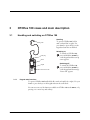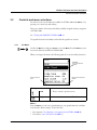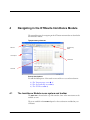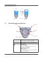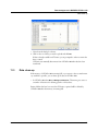
1
MADSEN OTOflex 100 & OTOsuite Immittance Module User Manual Doc no. 7-50-0880-EN/12 0459 Copyright notice No part of this Manual or program may be reproduced, stored in a retrieval system, or transmitted, in any form or by any means, electronic, mechanical, photocopying, recording, or otherwise, without the prior written consent of GN Otometrics A/S. Copyright© 2010, GN Otometrics A/S Printed in Denmark by GN Otometrics A/S, Denmark All information, illustrations, and specifications in this manual are based on the latest product information available at the time of publication. GN Otometrics A/S reserves the right to make changes at any time without notice. Version release date 7. June 2010 Technical support Please contact your supplier. FM template version: 01-02-2010 Table of Contents MADSEN OTOflex 100 & OTOsuite Immittance Module User Manual 1 Introduction . . . . . . . . . . . . . . . . . . . . . . . . . . . . . . . . . . . . . . . . . . . . . . . . . . . . . . . 11 1.1 MADSEN OTOflex 100 . . . . . . . . . . . . . . . . . . . . . . . . . . . . . . . . . . . . . . . . . . . . . . 1.2 OTOsuite and the Immittance Module . . . . . . . . . . . . . . . . . . . . . . . . . . . . . . . . . . . . 1.2.1 The flexibility of the OTOsuite Immittance Module . . . . . . . . . . . . . . . . . . . 1.3 Intended use . . . . . . . . . . . . . . . . . . . . . . . . . . . . . . . . . . . . . . . . . . . . . . . . . . . . . . . . 1.3.1 MADSEN OTOflex 100 . . . . . . . . . . . . . . . . . . . . . . . . . . . . . . . . . . . . . . . . 1.3.2 The Immittance Module . . . . . . . . . . . . . . . . . . . . . . . . . . . . . . . . . . . . . . . . 1.4 About this manual . . . . . . . . . . . . . . . . . . . . . . . . . . . . . . . . . . . . . . . . . . . . . . . . . . . . 1.4.1 Safety . . . . . . . . . . . . . . . . . . . . . . . . . . . . . . . . . . . . . . . . . . . . . . . . . . . . . . . 1.4.2 Installation . . . . . . . . . . . . . . . . . . . . . . . . . . . . . . . . . . . . . . . . . . . . . . . . . . . 1.4.3 Descriptions and testing . . . . . . . . . . . . . . . . . . . . . . . . . . . . . . . . . . . . . . . . . 1.4.4 Preparing for testing . . . . . . . . . . . . . . . . . . . . . . . . . . . . . . . . . . . . . . . . . . . . 1.4.5 Printing . . . . . . . . . . . . . . . . . . . . . . . . . . . . . . . . . . . . . . . . . . . . . . . . . . . . . 1.4.6 Maintenance and cleaning . . . . . . . . . . . . . . . . . . . . . . . . . . . . . . . . . . . . . . . 1.5 Typographical conventions . . . . . . . . . . . . . . . . . . . . . . . . . . . . . . . . . . . . . . . . . . . . . 1.5.1 Navigation . . . . . . . . . . . . . . . . . . . . . . . . . . . . . . . . . . . . . . . . . . . . . . . . . . . 2 Getting started with MADSEN OTOflex 100 and the OTOsuite Immittance Module . . . . . . . . . . . . . . . . . . . . . . . . . . . . . . . . . . 17 2.1 Unpacking . . . . . . . . . . . . . . . . . . . . . . . . . . . . . . . . . . . . . . . . . . . . . . . . . . . . . . . . . 2.2 Installation . . . . . . . . . . . . . . . . . . . . . . . . . . . . . . . . . . . . . . . . . . . . . . . . . . . . . . . . . 2.3 Starting up OTOflex 100 . . . . . . . . . . . . . . . . . . . . . . . . . . . . . . . . . . . . . . . . . . . . . . 2.3.1 Language setting . . . . . . . . . . . . . . . . . . . . . . . . . . . . . . . . . . . . . . . . . . . . . . 2.4 Starting up the Immittance Module . . . . . . . . . . . . . . . . . . . . . . . . . . . . . . . . . . . . . . 2.5 Immittance Module features . . . . . . . . . . . . . . . . . . . . . . . . . . . . . . . . . . . . . . . . . . . . 3 17 17 17 18 19 19 OTOflex 100 views and main description . . . . . . . . . . . . . . . . . . . . . . . . . . 21 3.1 Handling and switching on OTOflex 100 . . . . . . . . . . . . . . . . . . . . . . . . . . . . . . . . . . 3.1.1 Keypad main functions . . . . . . . . . . . . . . . . . . . . . . . . . . . . . . . . . . . . . . . . . 3.1.2 The display - test mode . . . . . . . . . . . . . . . . . . . . . . . . . . . . . . . . . . . . . . . . . 3.2 Controls and menu selections . . . . . . . . . . . . . . . . . . . . . . . . . . . . . . . . . . . . . . . . . . . 3.2.1 The Menu . . . . . . . . . . . . . . . . . . . . . . . . . . . . . . . . . . . . . . . . . . . . . . . . . . . 3.2.2 Test Selector mode . . . . . . . . . . . . . . . . . . . . . . . . . . . . . . . . . . . . . . . . . . . . . 3.2.3 The Text Editor . . . . . . . . . . . . . . . . . . . . . . . . . . . . . . . . . . . . . . . . . . . . . . . 3.2.4 The Tympanometric Curve Selector . . . . . . . . . . . . . . . . . . . . . . . . . . . . . . . 3.2.5 The OTOflex 100 Menu . . . . . . . . . . . . . . . . . . . . . . . . . . . . . . . . . . . . . . . . Otometrics 11 11 12 12 12 13 13 13 13 14 14 14 14 14 14 21 21 24 25 25 27 29 30 30 3 Table of Contents MADSEN OTOflex 100 & OTOsuite Immittance Module • User Manual 4 Navigating in the OTOsuite Immittance Module . . . . . . . . . . . . . . . . . . . 33 4.1 The Immittance Module menu system and toolbar . . . . . . . . . . . . . . . . . . . . . . . . . . 4.1.1 Edit menu . . . . . . . . . . . . . . . . . . . . . . . . . . . . . . . . . . . . . . . . . . . . . . . . . . . 4.1.2 Measurement menu . . . . . . . . . . . . . . . . . . . . . . . . . . . . . . . . . . . . . . . . . . . 4.1.3 Tools menu . . . . . . . . . . . . . . . . . . . . . . . . . . . . . . . . . . . . . . . . . . . . . . . . . . 4.1.4 Additional icons . . . . . . . . . . . . . . . . . . . . . . . . . . . . . . . . . . . . . . . . . . . . . . 4.2 The Immittance Module Control Panel . . . . . . . . . . . . . . . . . . . . . . . . . . . . . . . . . . . 4.2.1 Sequence selection . . . . . . . . . . . . . . . . . . . . . . . . . . . . . . . . . . . . . . . . . . . . . 4.2.2 Test control buttons . . . . . . . . . . . . . . . . . . . . . . . . . . . . . . . . . . . . . . . . . . . 4.2.3 Changing Control Panel settings . . . . . . . . . . . . . . . . . . . . . . . . . . . . . . . . . . 4.3 The Tympanometry screen . . . . . . . . . . . . . . . . . . . . . . . . . . . . . . . . . . . . . . . . . . . . . 4.4 The Acoustic Reflex screens . . . . . . . . . . . . . . . . . . . . . . . . . . . . . . . . . . . . . . . . . . . . 4.4.1 The Reflex Screening screen . . . . . . . . . . . . . . . . . . . . . . . . . . . . . . . . . . . . . 4.4.2 The Reflex Threshold screen . . . . . . . . . . . . . . . . . . . . . . . . . . . . . . . . . . . . . 4.4.3 The Reflex Decay screen . . . . . . . . . . . . . . . . . . . . . . . . . . . . . . . . . . . . . . . . 4.5 The ETF-P screen . . . . . . . . . . . . . . . . . . . . . . . . . . . . . . . . . . . . . . . . . . . . . . . . . . . 4.5.1 The post-analysis tool . . . . . . . . . . . . . . . . . . . . . . . . . . . . . . . . . . . . . . . . . . 5 Test Device Management in OTOsuite . . . . . . . . . . . . . . . . . . . . . . . . . . . . 45 5.1 Setting up communication with the test device . . . . . . . . . . . . . . . . . . . . . . . . . . . . . . 5.1.1 Selecting test devices . . . . . . . . . . . . . . . . . . . . . . . . . . . . . . . . . . . . . . . . . . . 5.1.2 Connection . . . . . . . . . . . . . . . . . . . . . . . . . . . . . . . . . . . . . . . . . . . . . . . . . . 5.1.3 Connecting to a test device . . . . . . . . . . . . . . . . . . . . . . . . . . . . . . . . . . . . . . 5.1.4 Reconnecting to a test device . . . . . . . . . . . . . . . . . . . . . . . . . . . . . . . . . . . . 5.1.5 Test device information . . . . . . . . . . . . . . . . . . . . . . . . . . . . . . . . . . . . . . . . 5.1.6 Firmware upgrade - test devices . . . . . . . . . . . . . . . . . . . . . . . . . . . . . . . . . . . 6 45 45 46 46 46 46 46 Preparing OTOflex 100 and the Immittance Module for testing . . . . 49 6.1 Preparing the test environment . . . . . . . . . . . . . . . . . . . . . . . . . . . . . . . . . . . . . . . . . . 6.1.1 The test environment . . . . . . . . . . . . . . . . . . . . . . . . . . . . . . . . . . . . . . . . . . 6.2 Hygienic precautions . . . . . . . . . . . . . . . . . . . . . . . . . . . . . . . . . . . . . . . . . . . . . . . . . 6.3 Preparing OTOflex 100 . . . . . . . . . . . . . . . . . . . . . . . . . . . . . . . . . . . . . . . . . . . . . . . 6.3.1 Preparing the probe . . . . . . . . . . . . . . . . . . . . . . . . . . . . . . . . . . . . . . . . . . . . 6.3.2 Using cap and/or handgrip . . . . . . . . . . . . . . . . . . . . . . . . . . . . . . . . . . . . . . 6.3.3 Probe check . . . . . . . . . . . . . . . . . . . . . . . . . . . . . . . . . . . . . . . . . . . . . . . . . . 6.3.4 Selecting patient folder and test type in OTOflex 100 . . . . . . . . . . . . . . . . . 6.3.5 Test flow setup . . . . . . . . . . . . . . . . . . . . . . . . . . . . . . . . . . . . . . . . . . . . . . . 6.3.6 Users . . . . . . . . . . . . . . . . . . . . . . . . . . . . . . . . . . . . . . . . . . . . . . . . . . . . . . . 6.4 Preparing the patient . . . . . . . . . . . . . . . . . . . . . . . . . . . . . . . . . . . . . . . . . . . . . . . . . 6.4.1 Fitting the eartip on the probe . . . . . . . . . . . . . . . . . . . . . . . . . . . . . . . . . . . 6.4.2 Fitting the probe in the patient’s ear . . . . . . . . . . . . . . . . . . . . . . . . . . . . . . . 6.4.3 Leakage . . . . . . . . . . . . . . . . . . . . . . . . . . . . . . . . . . . . . . . . . . . . . . . . . . . . . 6.5 Preparing for the next patient . . . . . . . . . . . . . . . . . . . . . . . . . . . . . . . . . . . . . . . . . . . 4 33 34 34 34 35 35 36 36 37 37 38 39 40 42 43 43 49 49 50 50 50 51 57 58 59 60 61 61 62 64 64 Otometrics Table of Contents MADSEN OTOflex 100 & OTOsuite Immittance Module • User Manual 7 Testing with MADSEN OTOflex 100 . . . . . . . . . . . . . . . . . . . . . . . . . . . . . . . 67 7.1 7.2 7.3 7.4 7.5 7.6 7.7 7.8 7.9 7.10 7.11 8 Fast diagnostics - the quick approach . . . . . . . . . . . . . . . . . . . . . . . . . . . . . . . . . . . . . General test softkeys and shortcuts . . . . . . . . . . . . . . . . . . . . . . . . . . . . . . . . . . . . . . . Start testing . . . . . . . . . . . . . . . . . . . . . . . . . . . . . . . . . . . . . . . . . . . . . . . . . . . . . . . . Sequence testing . . . . . . . . . . . . . . . . . . . . . . . . . . . . . . . . . . . . . . . . . . . . . . . . . . . . . 7.4.1 Selecting a test sequence . . . . . . . . . . . . . . . . . . . . . . . . . . . . . . . . . . . . . . . . 7.4.2 Running a test sequence from OTOflex 100 . . . . . . . . . . . . . . . . . . . . . . . . . Screening . . . . . . . . . . . . . . . . . . . . . . . . . . . . . . . . . . . . . . . . . . . . . . . . . . . . . . . . . . 7.5.1 Screening tympanometry . . . . . . . . . . . . . . . . . . . . . . . . . . . . . . . . . . . . . . . 7.5.2 Reflex screening . . . . . . . . . . . . . . . . . . . . . . . . . . . . . . . . . . . . . . . . . . . . . . 7.5.3 Settings - Screening . . . . . . . . . . . . . . . . . . . . . . . . . . . . . . . . . . . . . . . . . . . . Tympanometry . . . . . . . . . . . . . . . . . . . . . . . . . . . . . . . . . . . . . . . . . . . . . . . . . . . . . . 7.6.1 Tympanometry softkeys and shortcuts . . . . . . . . . . . . . . . . . . . . . . . . . . . . . 7.6.2 Diagnostic tympanometry . . . . . . . . . . . . . . . . . . . . . . . . . . . . . . . . . . . . . . . 7.6.3 The diagnostic tympanometry result . . . . . . . . . . . . . . . . . . . . . . . . . . . . . . . 7.6.4 Settings - Diagnostic tympanometry . . . . . . . . . . . . . . . . . . . . . . . . . . . . . . . ETF-I (Eustachian Tube Function - Intact) . . . . . . . . . . . . . . . . . . . . . . . . . . . . . . . . 7.7.1 Settings - ETF-I . . . . . . . . . . . . . . . . . . . . . . . . . . . . . . . . . . . . . . . . . . . . . . Acoustic reflex testing . . . . . . . . . . . . . . . . . . . . . . . . . . . . . . . . . . . . . . . . . . . . . . . . . Reflex Threshold testing . . . . . . . . . . . . . . . . . . . . . . . . . . . . . . . . . . . . . . . . . . . . . . . 7.9.1 Keys and functions . . . . . . . . . . . . . . . . . . . . . . . . . . . . . . . . . . . . . . . . . . . . 7.9.2 Automatic and semi-automatic Reflex Threshold testing . . . . . . . . . . . . . . . . 7.9.3 Viewing Reflex threshold results . . . . . . . . . . . . . . . . . . . . . . . . . . . . . . . . . . 7.9.4 Settings - Automatic and semi-automatic Reflex Threshold . . . . . . . . . . . . . 7.9.5 Manual Reflex Threshold testing . . . . . . . . . . . . . . . . . . . . . . . . . . . . . . . . . . 7.9.6 The Reflex Threshold results . . . . . . . . . . . . . . . . . . . . . . . . . . . . . . . . . . . . . 7.9.7 Manually selecting/deselecting Reflex Threshold values . . . . . . . . . . . . . . . . Reflex Decay testing . . . . . . . . . . . . . . . . . . . . . . . . . . . . . . . . . . . . . . . . . . . . . . . . . . 7.10.1 Keys and functions . . . . . . . . . . . . . . . . . . . . . . . . . . . . . . . . . . . . . . . . . . . . 7.10.2 Automatic Reflex Decay testing . . . . . . . . . . . . . . . . . . . . . . . . . . . . . . . . . . 7.10.3 Settings - Automatic Reflex Decay . . . . . . . . . . . . . . . . . . . . . . . . . . . . . . . . 7.10.4 The Reflex Decay results . . . . . . . . . . . . . . . . . . . . . . . . . . . . . . . . . . . . . . . . 7.10.5 Manual Reflex Decay . . . . . . . . . . . . . . . . . . . . . . . . . . . . . . . . . . . . . . . . . . ETF-P testing (Eustachian Tube Function - Perforated) . . . . . . . . . . . . . . . . . . . . . . . 7.11.1 Idle mode functions . . . . . . . . . . . . . . . . . . . . . . . . . . . . . . . . . . . . . . . . . . . 7.11.2 Pressure build functions . . . . . . . . . . . . . . . . . . . . . . . . . . . . . . . . . . . . . . . . 7.11.3 The test . . . . . . . . . . . . . . . . . . . . . . . . . . . . . . . . . . . . . . . . . . . . . . . . . . . . . 7.11.4 The ETF-P result . . . . . . . . . . . . . . . . . . . . . . . . . . . . . . . . . . . . . . . . . . . . . 7.11.5 The Immittance Module post-analysis tool - ETF-P . . . . . . . . . . . . . . . . . . . Managing Test Results in OTOflex 100 . . . . . . . . . . . . . . . . . . . . . . . . . . . 101 8.1 When testing is done . . . . . . . . . . . . . . . . . . . . . . . . . . . . . . . . . . . . . . . . . . . . . . . . 8.2 Swap ear results . . . . . . . . . . . . . . . . . . . . . . . . . . . . . . . . . . . . . . . . . . . . . . . . . . . . 8.3 Delete measurements . . . . . . . . . . . . . . . . . . . . . . . . . . . . . . . . . . . . . . . . . . . . . . . . 8.3.1 Tympanometry . . . . . . . . . . . . . . . . . . . . . . . . . . . . . . . . . . . . . . . . . . . . . . Otometrics 67 68 69 69 69 70 70 71 71 74 75 76 76 78 80 80 80 81 82 83 84 86 87 88 89 89 90 91 92 93 94 95 97 97 97 98 99 99 101 101 101 101 5 Table of Contents MADSEN OTOflex 100 & OTOsuite Immittance Module • User Manual 8.3.2 Reflex Threshold . . . . . . . . . . . . . . . . . . . . . . . . . . . . . . . . . . . . . . . . . . . . . 8.4 Deleting Test Results . . . . . . . . . . . . . . . . . . . . . . . . . . . . . . . . . . . . . . . . . . . . . . . . 8.5 Communicating and synchronizing with OTOsuite . . . . . . . . . . . . . . . . . . . . . . . . . 8.5.1 Synchronizing data . . . . . . . . . . . . . . . . . . . . . . . . . . . . . . . . . . . . . . . . . . . 8.5.2 Synchronization of corrections made to Patient Folders . . . . . . . . . . . . . . . 9 101 102 102 103 103 Printing . . . . . . . . . . . . . . . . . . . . . . . . . . . . . . . . . . . . . . . . . . . . . . . . . . . . . . . . . . 105 10 Testing with the OTOsuite Immittance Module . . . . . . . . . . . . . . . . . . . 107 10.1 Sequence testing . . . . . . . . . . . . . . . . . . . . . . . . . . . . . . . . . . . . . . . . . . . . . . . . . . . . 10.1.1 Selecting a test sequence . . . . . . . . . . . . . . . . . . . . . . . . . . . . . . . . . . . . . . . 10.1.2 T + RS (Tympanometry + Reflex Screening) . . . . . . . . . . . . . . . . . . . . . . . . 10.1.3 T + RT (Tympanometry + Reflex Thresholds) . . . . . . . . . . . . . . . . . . . . . . 10.1.4 T + RT + RD (Tympanometry + Reflex Threshold + Reflex Decay) . . . . . . 10.1.5 Running a test sequence from the Immittance Module . . . . . . . . . . . . . . . . 10.2 Screening . . . . . . . . . . . . . . . . . . . . . . . . . . . . . . . . . . . . . . . . . . . . . . . . . . . . . . . . . 10.2.1 Screening tympanometry . . . . . . . . . . . . . . . . . . . . . . . . . . . . . . . . . . . . . . 10.2.2 Acoustic Reflex Screening . . . . . . . . . . . . . . . . . . . . . . . . . . . . . . . . . . . . . . 10.3 Tympanometric testing . . . . . . . . . . . . . . . . . . . . . . . . . . . . . . . . . . . . . . . . . . . . . . 10.3.1 Diagnostic tympanometry . . . . . . . . . . . . . . . . . . . . . . . . . . . . . . . . . . . . . . 10.3.2 ETF-I, Eustachian Tube Function - Intact . . . . . . . . . . . . . . . . . . . . . . . . . 10.4 Acoustic Reflex Threshold testing . . . . . . . . . . . . . . . . . . . . . . . . . . . . . . . . . . . . . . . 10.4.1 Automatic and semiautomatic threshold testing . . . . . . . . . . . . . . . . . . . . . 10.4.2 Manual threshold testing . . . . . . . . . . . . . . . . . . . . . . . . . . . . . . . . . . . . . . . 10.5 Acoustic Reflex Decay testing . . . . . . . . . . . . . . . . . . . . . . . . . . . . . . . . . . . . . . . . . . 10.5.1 Automatic Acoustic Reflex Decay testing . . . . . . . . . . . . . . . . . . . . . . . . . . 10.5.2 Manual Acoustic Reflex Decay testing . . . . . . . . . . . . . . . . . . . . . . . . . . . . . 10.6 ETF-P (Eustachian Tube Function - Perforated) . . . . . . . . . . . . . . . . . . . . . . . . . . . 10.7 Managing test results . . . . . . . . . . . . . . . . . . . . . . . . . . . . . . . . . . . . . . . . . . . . . . . . 10.7.1 Tests and subtests . . . . . . . . . . . . . . . . . . . . . . . . . . . . . . . . . . . . . . . . . . . . 10.7.2 Swapping ear data . . . . . . . . . . . . . . . . . . . . . . . . . . . . . . . . . . . . . . . . . . . . 10.7.3 Deleting data . . . . . . . . . . . . . . . . . . . . . . . . . . . . . . . . . . . . . . . . . . . . . . . 10.8 Leakage . . . . . . . . . . . . . . . . . . . . . . . . . . . . . . . . . . . . . . . . . . . . . . . . . . . . . . . . . . 10.9 Testing the other ear . . . . . . . . . . . . . . . . . . . . . . . . . . . . . . . . . . . . . . . . . . . . . . . . . 10.10Saving measurements . . . . . . . . . . . . . . . . . . . . . . . . . . . . . . . . . . . . . . . . . . . . . . . . 10.10.1 Standards used in NOAH . . . . . . . . . . . . . . . . . . . . . . . . . . . . . . . . . . . . . . 10.11Preparing for the next patient . . . . . . . . . . . . . . . . . . . . . . . . . . . . . . . . . . . . . . . . . 107 107 107 108 108 108 109 109 110 112 112 114 114 115 119 121 122 123 125 126 126 126 127 127 128 128 128 129 11 Data management in MADSEN OTOflex 100 . . . . . . . . . . . . . . . . . . . . . . 131 11.1 Data handling . . . . . . . . . . . . . . . . . . . . . . . . . . . . . . . . . . . . . . . . . . . . . . . . . . . . . 11.1.1 Interruption of communication . . . . . . . . . . . . . . . . . . . . . . . . . . . . . . . . . 11.1.2 Synchronization . . . . . . . . . . . . . . . . . . . . . . . . . . . . . . . . . . . . . . . . . . . . . 11.2 Uploading test results to OTOsuite . . . . . . . . . . . . . . . . . . . . . . . . . . . . . . . . . . . . . 11.3 Data clean-up . . . . . . . . . . . . . . . . . . . . . . . . . . . . . . . . . . . . . . . . . . . . . . . . . . . . . . 6 131 131 131 132 133 Otometrics Table of Contents MADSEN OTOflex 100 & OTOsuite Immittance Module • User Manual 12 Immittance test setup in MADSEN OTOflex 100 . . . . . . . . . . . . . . . . . . 135 12.1 Test settings . . . . . . . . . . . . . . . . . . . . . . . . . . . . . . . . . . . . . . . . . . . . . . . . . . . . . . . 12.1.1 Changing individual settings . . . . . . . . . . . . . . . . . . . . . . . . . . . . . . . . . . . . 12.1.2 Uploading test settings to the Immittance Module . . . . . . . . . . . . . . . . . . . 12.1.3 Creating a setup . . . . . . . . . . . . . . . . . . . . . . . . . . . . . . . . . . . . . . . . . . . . . 12.1.4 Editing a test setup . . . . . . . . . . . . . . . . . . . . . . . . . . . . . . . . . . . . . . . . . . . 12.1.5 Using a test setup . . . . . . . . . . . . . . . . . . . . . . . . . . . . . . . . . . . . . . . . . . . . 12.2 General actions . . . . . . . . . . . . . . . . . . . . . . . . . . . . . . . . . . . . . . . . . . . . . . . . . . . . . 12.2.1 Manage test results . . . . . . . . . . . . . . . . . . . . . . . . . . . . . . . . . . . . . . . . . . . 12.2.2 Procedure options . . . . . . . . . . . . . . . . . . . . . . . . . . . . . . . . . . . . . . . . . . . . 12.2.3 Advanced.. . . . . . . . . . . . . . . . . . . . . . . . . . . . . . . . . . . . . . . . . . . . . . . . . . 12.2.4 Device settings . . . . . . . . . . . . . . . . . . . . . . . . . . . . . . . . . . . . . . . . . . . . . . 12.3 Tympanometry setup . . . . . . . . . . . . . . . . . . . . . . . . . . . . . . . . . . . . . . . . . . . . . . . . 12.3.1 Screening tympanometry . . . . . . . . . . . . . . . . . . . . . . . . . . . . . . . . . . . . . . 12.3.2 ETF-I setup . . . . . . . . . . . . . . . . . . . . . . . . . . . . . . . . . . . . . . . . . . . . . . . . 12.4 Acoustic Reflex Screening setup . . . . . . . . . . . . . . . . . . . . . . . . . . . . . . . . . . . . . . . . 12.5 Acoustic Reflex Threshold setup . . . . . . . . . . . . . . . . . . . . . . . . . . . . . . . . . . . . . . . . 12.6 Acoustic Reflex Decay setup . . . . . . . . . . . . . . . . . . . . . . . . . . . . . . . . . . . . . . . . . . . 12.7 ETF-P setup . . . . . . . . . . . . . . . . . . . . . . . . . . . . . . . . . . . . . . . . . . . . . . . . . . . . . . . 12.8 Test sequences . . . . . . . . . . . . . . . . . . . . . . . . . . . . . . . . . . . . . . . . . . . . . . . . . . . . . 12.8.1 Selecting a sequence setup . . . . . . . . . . . . . . . . . . . . . . . . . . . . . . . . . . . . . . 135 135 137 138 138 138 139 139 141 144 145 148 152 152 153 156 163 165 166 167 13 Immittance Module Tools Options (view and measurement options) . . . . . . . . . . . . . . . . . . . . . . . . . . . . . . . . 169 13.1 General settings . . . . . . . . . . . . . . . . . . . . . . . . . . . . . . . . . . . . . . . . . . . . . . . . . . . . 13.1.1 Available settings . . . . . . . . . . . . . . . . . . . . . . . . . . . . . . . . . . . . . . . . . . . . . 13.2 View settings . . . . . . . . . . . . . . . . . . . . . . . . . . . . . . . . . . . . . . . . . . . . . . . . . . . . . . 13.2.1 Tymp. and Reflex Scr. view settings . . . . . . . . . . . . . . . . . . . . . . . . . . . . . . 13.2.2 Reflex Threshold view settings . . . . . . . . . . . . . . . . . . . . . . . . . . . . . . . . . . 13.2.3 Reflex Decay view settings . . . . . . . . . . . . . . . . . . . . . . . . . . . . . . . . . . . . . . 13.2.4 ETF-P view settings . . . . . . . . . . . . . . . . . . . . . . . . . . . . . . . . . . . . . . . . . . 13.3 Measurement settings . . . . . . . . . . . . . . . . . . . . . . . . . . . . . . . . . . . . . . . . . . . . . . . . 13.3.1 Tympanometry setup . . . . . . . . . . . . . . . . . . . . . . . . . . . . . . . . . . . . . . . . . 13.3.2 ETF-I Setup . . . . . . . . . . . . . . . . . . . . . . . . . . . . . . . . . . . . . . . . . . . . . . . . 13.3.3 Acoustic Reflex Screening setup . . . . . . . . . . . . . . . . . . . . . . . . . . . . . . . . . 13.3.4 Acoustic Reflex Threshold setup . . . . . . . . . . . . . . . . . . . . . . . . . . . . . . . . . 13.3.5 Reflex Decay setup . . . . . . . . . . . . . . . . . . . . . . . . . . . . . . . . . . . . . . . . . . . 13.3.6 ETF-P setup . . . . . . . . . . . . . . . . . . . . . . . . . . . . . . . . . . . . . . . . . . . . . . . . 169 169 171 171 174 175 175 175 176 179 179 181 186 189 14 OTOflex 100 Service and Maintenance . . . . . . . . . . . . . . . . . . . . . . . . . . . 191 14.1 Equipment failure . . . . . . . . . . . . . . . . . . . . . . . . . . . . . . . . . . . . . . . . . . . . . . . . . . . 14.2 Service and repair . . . . . . . . . . . . . . . . . . . . . . . . . . . . . . . . . . . . . . . . . . . . . . . . . . . 14.3 Maintenance . . . . . . . . . . . . . . . . . . . . . . . . . . . . . . . . . . . . . . . . . . . . . . . . . . . . . . . 14.3.1 Calibration . . . . . . . . . . . . . . . . . . . . . . . . . . . . . . . . . . . . . . . . . . . . . . . . . Otometrics 191 191 191 192 7 Table of Contents MADSEN OTOflex 100 & OTOsuite Immittance Module • User Manual 14.3.2 Probe cleaning and maintenance . . . . . . . . . . . . . . . . . . . . . . . . . . . . . . . . . 14.4 Cleaning and disinfecting the probe tip . . . . . . . . . . . . . . . . . . . . . . . . . . . . . . . . . . 14.4.1 Changing the wax filter . . . . . . . . . . . . . . . . . . . . . . . . . . . . . . . . . . . . . . . . 14.5 Cleaning OTOflex 100 . . . . . . . . . . . . . . . . . . . . . . . . . . . . . . . . . . . . . . . . . . . . . . 14.5.1 Eartips . . . . . . . . . . . . . . . . . . . . . . . . . . . . . . . . . . . . . . . . . . . . . . . . . . . . 14.5.2 Disposal of disposable articles . . . . . . . . . . . . . . . . . . . . . . . . . . . . . . . . . . . 14.5.3 Batteries and charger . . . . . . . . . . . . . . . . . . . . . . . . . . . . . . . . . . . . . . . . . . 14.5.4 Safety information . . . . . . . . . . . . . . . . . . . . . . . . . . . . . . . . . . . . . . . . . . . 14.5.5 Environmental protection . . . . . . . . . . . . . . . . . . . . . . . . . . . . . . . . . . . . . . 192 193 195 195 196 196 196 197 198 15 Installing MADSEN OTOflex 100 . . . . . . . . . . . . . . . . . . . . . . . . . . . . . . . . . 199 15.1 Unpacking OTOflex 100 . . . . . . . . . . . . . . . . . . . . . . . . . . . . . . . . . . . . . . . . . . . . . 15.2 Storing OTOflex 100 . . . . . . . . . . . . . . . . . . . . . . . . . . . . . . . . . . . . . . . . . . . . . . . . 15.3 Views of OTOflex 100 . . . . . . . . . . . . . . . . . . . . . . . . . . . . . . . . . . . . . . . . . . . . . . . 15.3.1 Front view . . . . . . . . . . . . . . . . . . . . . . . . . . . . . . . . . . . . . . . . . . . . . . . . . . 15.3.2 Top view . . . . . . . . . . . . . . . . . . . . . . . . . . . . . . . . . . . . . . . . . . . . . . . . . . . 15.3.3 Bottom view . . . . . . . . . . . . . . . . . . . . . . . . . . . . . . . . . . . . . . . . . . . . . . . . 15.3.4 Reverse side view . . . . . . . . . . . . . . . . . . . . . . . . . . . . . . . . . . . . . . . . . . . . . 15.3.5 The charger . . . . . . . . . . . . . . . . . . . . . . . . . . . . . . . . . . . . . . . . . . . . . . . . . 15.4 The probe . . . . . . . . . . . . . . . . . . . . . . . . . . . . . . . . . . . . . . . . . . . . . . . . . . . . . . . . . 15.5 Assembly and installation . . . . . . . . . . . . . . . . . . . . . . . . . . . . . . . . . . . . . . . . . . . . . 15.5.1 Location . . . . . . . . . . . . . . . . . . . . . . . . . . . . . . . . . . . . . . . . . . . . . . . . . . . 15.5.2 Desktop installation . . . . . . . . . . . . . . . . . . . . . . . . . . . . . . . . . . . . . . . . . . 15.5.3 Wall mount installation . . . . . . . . . . . . . . . . . . . . . . . . . . . . . . . . . . . . . . . 15.6 Powering . . . . . . . . . . . . . . . . . . . . . . . . . . . . . . . . . . . . . . . . . . . . . . . . . . . . . . . . . 15.6.1 Powering OTOflex 100 . . . . . . . . . . . . . . . . . . . . . . . . . . . . . . . . . . . . . . . 15.6.2 Batteries . . . . . . . . . . . . . . . . . . . . . . . . . . . . . . . . . . . . . . . . . . . . . . . . . . . 15.6.3 The charger . . . . . . . . . . . . . . . . . . . . . . . . . . . . . . . . . . . . . . . . . . . . . . . . . 15.6.4 Switching on OTOflex 100 . . . . . . . . . . . . . . . . . . . . . . . . . . . . . . . . . . . . 15.6.5 Bluetooth . . . . . . . . . . . . . . . . . . . . . . . . . . . . . . . . . . . . . . . . . . . . . . . . . . 199 199 199 200 200 201 201 201 202 202 202 203 204 206 206 206 209 210 210 16 Configuring OTOsuite . . . . . . . . . . . . . . . . . . . . . . . . . . . . . . . . . . . . . . . . . . . 213 App. 1 Standards and safety - OTOflex 100 and the Immittance Module . . . . . . . . . . . . . . . . . . . . . . . . . . . . . . . . . . . 215 App. 1.1 Symbols used . . . . . . . . . . . . . . . . . . . . . . . . . . . . . . . . . . . . . . App. 1.1.1 OTOflex 100 symbols . . . . . . . . . . . . . . . . . . . . . . . . App. 1.1.2 Charger unit symbols . . . . . . . . . . . . . . . . . . . . . . . . . App. 1.1.3 The OTOsuite Audiometry Module . . . . . . . . . . . . . App. 1.2 Warning notes . . . . . . . . . . . . . . . . . . . . . . . . . . . . . . . . . . . . . App. 1.2.1 OTOflex 100 warning notes . . . . . . . . . . . . . . . . . . . App. 1.2.2 Charger unit warning notes . . . . . . . . . . . . . . . . . . . . App. 1.3 Manufacturer . . . . . . . . . . . . . . . . . . . . . . . . . . . . . . . . . . . . . App. 1.3.1 Responsibility of the manufacturer . . . . . . . . . . . . . . . 8 215 215 216 217 217 217 219 219 219 Otometrics Table of Contents MADSEN OTOflex 100 & OTOsuite Immittance Module • User Manual App. 2 MADSEN OTOflex 100 Immittance Methodology and Features . . . . . . . . . . . . . . . . . . . . . . . . . . . . . . . 221 App. 2.1 An introduction to immittance . . . . . . . . . . . . . . . . . . . . . . . . App. 2.1.1 Immittance testing . . . . . . . . . . . . . . . . . . . . . . . . . . . App. 2.2 Tympanometry . . . . . . . . . . . . . . . . . . . . . . . . . . . . . . . . . . . . App. 2.2.1 Tympanometry testing on infants . . . . . . . . . . . . . . . App. 2.2.2 Tympanometric features . . . . . . . . . . . . . . . . . . . . . . App. 2.2.3 ETF-I (Eustachian Tube Function - Intact) . . . . . . . . App. 2.2.4 Valsalva’s Maneuver . . . . . . . . . . . . . . . . . . . . . . . . . . App. 2.2.5 Toynbee’s Maneuver . . . . . . . . . . . . . . . . . . . . . . . . . App. 2.3 Acoustic Reflex testing . . . . . . . . . . . . . . . . . . . . . . . . . . . . . . . App. 2.3.1 Acoustic Reflex Screening . . . . . . . . . . . . . . . . . . . . . App. 2.3.2 Acoustic Reflex Threshold . . . . . . . . . . . . . . . . . . . . . App. 2.3.3 Acoustic reflex decay . . . . . . . . . . . . . . . . . . . . . . . . . App. 2.3.4 Admittance monitoring . . . . . . . . . . . . . . . . . . . . . . . App. 2.4 ETF-P (Eustachian Tube Function - Perforated) . . . . . . . . . . . App. 2.5 Susceptance and Conductance, B/G . . . . . . . . . . . . . . . . . . . . App. 2.5.1 Susceptance, B . . . . . . . . . . . . . . . . . . . . . . . . . . . . . . App. 2.5.2 Conductance, G . . . . . . . . . . . . . . . . . . . . . . . . . . . . . App. 2.5.3 B/G viewing of tympanograms . . . . . . . . . . . . . . . . . . App. 2.5.4 Component compensation . . . . . . . . . . . . . . . . . . . . . App. 3 Glossary . . . . . . . . . . . . . . . . . . . . . . . . . . . . . . . . . . . . . . . . . . . . . . . . . 235 App. 3.1 App. 3.2 App. 4 Navigation and editing symbols . . . . . . . . . . . . . . . . . . . . . . . . Powering . . . . . . . . . . . . . . . . . . . . . . . . . . . . . . . . . . . . . . . . . Communication . . . . . . . . . . . . . . . . . . . . . . . . . . . . . . . . . . . Messages . . . . . . . . . . . . . . . . . . . . . . . . . . . . . . . . . . . . . . . . . Leakage . . . . . . . . . . . . . . . . . . . . . . . . . . . . . . . . . . . . . . . . . . Powering . . . . . . . . . . . . . . . . . . . . . . . . . . . . . . . . . . . . . . . . . Testing . . . . . . . . . . . . . . . . . . . . . . . . . . . . . . . . . . . . . . . . . . Communication . . . . . . . . . . . . . . . . . . . . . . . . . . . . . . . . . . . Probe-fit related problems . . . . . . . . . . . . . . . . . . . . . . . . . . . . 253 253 254 254 Technical Specifications - MADSEN OTOflex 100 . . . . . . . . . 255 App. 6.1 OTOflex 100 . . . . . . . . . . . . . . . . . . . . . . . . . . . . . . . . . . . . . App. 6.1.1 Compliance measuring system . . . . . . . . . . . . . . . . . . App. 6.1.2 Acoustic Reflex . . . . . . . . . . . . . . . . . . . . . . . . . . . . . App. 6.1.3 Air pressure system . . . . . . . . . . . . . . . . . . . . . . . . . . . Otometrics 249 250 250 250 251 Troubleshooting . . . . . . . . . . . . . . . . . . . . . . . . . . . . . . . . . . . . . . . . . 253 App. 5.1 App. 5.2 App. 5.3 App. 5.4 App. 6 Terminology . . . . . . . . . . . . . . . . . . . . . . . . . . . . . . . . . . . . . . 235 Abbreviations . . . . . . . . . . . . . . . . . . . . . . . . . . . . . . . . . . . . . 246 MADSEN OTOflex 100 Icons . . . . . . . . . . . . . . . . . . . . . . . . . . . . . . 249 App. 4.1 App. 4.2 App. 4.3 App. 4.4 App. 4.5 App. 5 221 221 222 222 223 225 226 226 226 227 228 228 229 229 229 230 231 232 232 255 255 255 256 9 Table of Contents MADSEN OTOflex 100 & OTOsuite Immittance Module • User Manual App. 6.1.4 Unit of admittance graph Y-axis . . . . . . . . . . . . . . . . . App. 6.1.5 Unit of graph X-axis . . . . . . . . . . . . . . . . . . . . . . . . . . App. 6.1.6 Display . . . . . . . . . . . . . . . . . . . . . . . . . . . . . . . . . . . . App. 6.1.7 Interface . . . . . . . . . . . . . . . . . . . . . . . . . . . . . . . . . . . App. 6.1.8 Type identification . . . . . . . . . . . . . . . . . . . . . . . . . . . App. 6.1.9 Power supply . . . . . . . . . . . . . . . . . . . . . . . . . . . . . . . App. 6.2 Charger unit . . . . . . . . . . . . . . . . . . . . . . . . . . . . . . . . . . . . . . App. 6.3 Operating environment . . . . . . . . . . . . . . . . . . . . . . . . . . . . . . App. 6.4 Storing and handling . . . . . . . . . . . . . . . . . . . . . . . . . . . . . . . . App. 6.5 Dimensions . . . . . . . . . . . . . . . . . . . . . . . . . . . . . . . . . . . . . . . App. 6.6 Weight . . . . . . . . . . . . . . . . . . . . . . . . . . . . . . . . . . . . . . . . . . App. 6.7 Miscellaneous . . . . . . . . . . . . . . . . . . . . . . . . . . . . . . . . . . . . . App. 6.8 Calibration . . . . . . . . . . . . . . . . . . . . . . . . . . . . . . . . . . . . . . . App. 6.9 Standards . . . . . . . . . . . . . . . . . . . . . . . . . . . . . . . . . . . . . . . . . 257 257 257 257 257 257 257 258 258 258 258 258 259 259 Index . . . . . . . . . . . . . . . . . . . . . . . . . . . . . . . . . . . . . . . . . . . . . . . . . . . . . . . . . . . . . . . . 261 10 Otometrics 1 Introduction 1.1 MADSEN OTOflex 100 Thank you for purchasing OTOflex 100. OTOflex 100 is a compact and portable wireless immittance test device, which offers a complete range of capabilities for middle ear diagnostics. OTOflex 100 can be operated anywhere as a stand-alone device or operated directly from OTOsuite. OTOflex 100 integrates closely with the OTOsuite Immittance Module, with full test control from both the device and OTOsuite. When used with OTOsuite, you gain additional features and diagnostic value offered by the comprehensive user interface and NOAH compatibility of OTOsuite. OTOflex 100 - OTOsuite interfacing OTOflex 100 is designed to operate with the OTOsuite Immittance Module. Bluetooth OTOflex 100 connects with OTOsuite via BluetoothTM, which provides wireless connection between OTOflex 100 and OTOsuite up to a range of approximately 10 metres (approx. 33 ft), and up to a range of 100 metres (approx. 330 ft) for other electronic devices. NOAH 3 The NOAH System is a HIMSA product for managing clients/patients, launching hearing test applications and fitting software, and storing audiological test results. OTOflex 100 test results can be stored in the NOAH 3 database via OTOsuite. 1.2 OTOsuite and the Immittance Module The OTOsuite Immittance Module offers real time presentation of test results and full test control of MADSEN OTOflex 100 directly from a PC. Test devices with integrated user interfaces can be operated independently of the Immittance Module, although additional features and diagnostic value is offered by the Immittance Module's comprehensive user interface and NOAH compatibility. The test functionalities of the OTOsuite Immittance Module depend on the connected device, as does the selection of test parameters, and remote control. Otometrics 11 Introduction Intended use The OTOsuite Immittance Module lets you work with NOAH or save and view results via XML files. The OTOsuite Immittance Module supports • • • • • screening and diagnostic tympanometry Reflex Threshold testing Reflex Decay testing ETF-P user-defined tests. Immittance Module - OTOflex 100 interfacing The Immittance Module is designed to operate with OTOflex 100 as the test device (produced by Otometrics). 1.2.1 The flexibility of the OTOsuite Immittance Module When used for testing, the OTOsuite Immittance Module adapts to the connected test device. Consequently, the test functionalities of the OTOsuite Immittance Module depend on the connected device, as does the selection of test parameters, and remote control. 1.3 Intended use 1.3.1 MADSEN OTOflex 100 OTOflex 100 is an audiodiagnostic device intended for clinical, diagnostic and screening tympanometry and reflex measurements performed by audiologists, ENTs and other health care professionals. It is designed for use on infants, children and adults, and is lightweight, fast, reliable, and easy to use. OTOflex 100 uses technologies which are highly effective for clinical and screening purposes. Tympanometry and Acoustic Reflex measurements measure the mechanical response of the middle ear and form a basis for evaluating whether the related physiological structures are functioning correctly or not. The OTOflex 100 probe is extremely lightweight (only 4.5 grams), and comes with comfortable, easy to insert eartips. This makes it ideal for use with children and adults. OTOflex 100 can be configured for a wide variety of tests, and it can be operated entirely manually or programmed for the user’s own combination of manual and automatic operation. In user-programmable tests the user can select the default parameters of a particular test, and combine tests to form a sequence of preset tests. 12 Otometrics Introduction About this manual 1.3.2 The Immittance Module The Immittance Module is intended for clinical, diagnostic and screening tympanometry and reflex measurements performed by audiologists, ENTs and other health care professionals. 1.4 About this manual This is your guide to using MADSEN OTOflex 100 and the OTOsuite Immittance Module. It also introduces you to the key features of the program by providing you with working scenarios for performing tests and viewing and printing test results. We recommend that you read this manual and make yourself familiar with the OTOflex 100 and how it operates with the OTOsuite Immittance Module so that you become familiar with the device before testing on a client. Note · If you are using the OTOsuite Immittance Module with NOAH 3, we recommend that you are familiar with the screens and functions provided in NOAH 3. We recommend that you make yourself familiar with the issues listed below: 1.4.1 Safety This manual contains information and warnings which must be followed to ensure the safe performance of OTOflex 100. Warning · Local government rules and regulations, if applicable, should also be followed at all times. Safety information is stated where it is relevant, and general safety aspects are described in App. 1 Standards and safety - OTOflex 100 and the Immittance Module 215. 1.4.2 Installation • To install the new system, see 15 Installing MADSEN OTOflex 100 199. Installation of OTOsuite is described in detail in the OTOsuite User Manual. Connecting to OTOflex 100 • See the OTOsuite User Manual. Configuring the OTOsuite Immittance Module • See 16 Configuring OTOsuite 213. Basic OTOsuite functions The basic OTOsuite functions are described in the OTOsuite User Manual. Otometrics 13 Introduction Typographical conventions 1.4.3 Descriptions and testing If your new system is already installed, see • 2 Getting started with MADSEN OTOflex 100 and the OTOsuite Immittance Module 17 • 4 Navigating in the OTOsuite Immittance Module 33 • 7 Testing with MADSEN OTOflex 100 67 1.4.4 Preparing for testing Before you receive the client and start the session of testing and explaining test results, your time is well spent preparing for the session. See 6 Preparing OTOflex 100 and the Immittance Module for testing 49. 1.4.5 Printing • For instructions on how to print OTOflex 100 results, see 9 Printing 105. • For instructions on how to print from the PC, see 14 OTOflex 100 Service and Maintenance 191. 1.4.6 Maintenance and cleaning For instructions on how and when to clean OTOflex 100, please see the OTOflex 100 Guide. We recommend that you take particular note of the cleaning and maintenance instructions. Failure to use and maintain the OTOflex 100 correctly may void your warranty. 1.5 Typographical conventions The use of WARNING, CAUTION and NOTE For safety reasons and appropriate use of OTOflex 100, the Guide contains WARNINGS, CAUTIONS and NOTES, which you should read carefully. Warning · indicates that there is risk of danger to persons and/or device. Caution · indicates that there is risk of damage to the device. Note · indicates that you should take special notice. 1.5.1 Navigation Menus, icons and functions to select are shown in bold type, as for instance in: 14 Otometrics Introduction Typographical conventions • Click the Set options icon on the toolbar or select Tools > Options.. Otometrics 15 Introduction Typographical conventions 16 Otometrics 2 Getting started with MADSEN OTOflex 100 and the OTOsuite Immittance Module 2.1 Unpacking 1. Inspect the package and its contents for possible visual damage. 2. Check with the packing list to make sure that you have received all necessary parts and accessories. If your package is incomplete, contact your supplier. 2.2 Installation 1. Install OTOsuite from the OTOsuite Installation CD. See the OTOsuite User Manual. 2. Install OTOflex 100 as described in 15 Installing MADSEN OTOflex 100 199. 2.3 Starting up OTOflex 100 1. Starting up OTOsuite is described in the OTOsuite User Manual. 2. To switch on OTOflex 100 press the On/Off key. On/Off Press & hold to switch on/off. Otometrics 17 Getting started with MADSEN OTOflex 100 and the OTOsuite Immittance Module Starting up OTOflex 100 Handling Probe To operate OTOflex 100, hold it with one hand (left or right). Use your thumb to press the keys on the keypad and turn the scroll wheel. Switching on Probe plug Screen Keypad Device colour code To switch on OTOflex 100, press and hold the On/Off key on the keypad until the start-up screen appears. Switching off To switch off OTOflex 100, press and hold the On/Off key on the keypad until the message “Power Off ” appears. When you have installed OTOflex 100, there are a number of settings you can customise for your use. See 12.2.4 Device settings 145. • • • • Check the specific device settings. If required, adjust the altitude setting. Set up the user(s) who will be using OTOflex 100. See 6.3.6 Users 60 Check the default test settings to acquaint yourself with the various settings. See 12.1 Test settings 135. • If required, create new test settings to suit your methods of testing. 2.3.1 Language setting If the language setting in your OTOflex 100 has not been set to your local language from the factory, select the appropriate language: 1. Switch on your OTOflex 100. – If the “Patient & User” screen appears, press the softkey Return to previous to go to the Tympanometry test screen. menu – If the “Load Settings” screen appears (depending on setting in Menu > Procedure Options > ‘Settings’ prompt), press the left softkey Cancel to go to the Tympanometry test screen. 18 Otometrics Getting started with MADSEN OTOflex 100 and the OTOsuite Immittance Module Starting up the Immittance Module 2. With the cursor highlighting the Menu icon to activate the Menu. , press Select 3. Use the Scroll Wheel to scroll to Advanced.. and press Select 4. Scroll to Device Settings.. and press Select 5. Scroll to Localization.. and press Select 6. With Language highlighted, press Select on the keypad . . . to access the language options. 7. Scroll to the language of your choice and press Select . to go to the Tympanometry test 8. Press the softkey Return to test screen screen. 2.4 Starting up the Immittance Module Starting the Immittance Module depends on the setup of the program. 1. Switch on OTOflex 100, if you wish to test patients or transfer test results. 2. Follow the instructions in the OTOsuite User Manual. – Select or create a client in OTOsuite. – Select the test type. – Activate the Control Panel. – Select test ear. 2.5 Immittance Module features General features Depending on the configuration of OTOflex 100 and the Immittance Module, you can • handle patient lists, • view and print test results, • view the progression of a range of tests online, • view historic tympanometry results from NOAH or XML, • view online tympanometry results during testing, • perform “over the rim” testing, using the audiometer as a handy control panel while you follow stimulus settings and test progress on your PC display, • plan patients for offline testing, • upload test results from offline tests. The basic Immittance Module functions are described in 4 Navigating in the OTOsuite Immittance Module 33. Otometrics 19 Getting started with MADSEN OTOflex 100 and the OTOsuite Immittance Module Immittance Module features Preparing for testing Before you receive the client and start the session of testing and explaining test results, your time is well spent preparing for the session. • Test preparations are described in 6 Preparing OTOflex 100 and the Immittance Module for testing 49. 20 Otometrics 3 OTOflex 100 views and main description 3.1 Handling and switching on OTOflex 100 Handling Probe To operate OTOflex 100, hold it with one hand (left or right). Use your thumb to press the keys on the keypad and turn the scroll wheel. Switching on Probe plug Screen Keypad Device colour code 3.1.1 To switch on OTOflex 100, press and hold the On/Off key on the keypad until the start-up screen appears. Switching off To switch off OTOflex 100, press and hold the On/Off key on the keypad until the message “Power Off ” appears. Keypad main functions To operate OTOflex 100 hand-held, hold it with one hand (left or right). Use your thumb to press the keys on the keypad and turn the scroll wheel. You can access most of the functions available in OTOflex 100 via the Menu, or by pressing one or more keys and softkeys. Otometrics 21 OTOflex 100 views and main description Handling and switching on OTOflex 100 Left softkey Right softkey On/Off Press & hold Press & hold to switch on/off. Press to toggle between test modes Ear Selector Pressure release Select key Select highlighted item. Toggle value settings Press & hold to activate: –Test Selector – Character Select in text editor mode Scroll wheel Scroll to highlight item Change intensity level Scroll to value setting Scroll between test types Scroll wheel Turn the scroll wheel to shift the focus on the screen or change values: • Scroll up Turn counter-clockwise to scroll up. Moves the focus up or to the left, or decreases a selected value • Scroll down Turn clockwise to scroll down Moves the focus down or to the right, or increases a selected value • Select Press and hold to activate the Test Selector (see 3.2.2 Test Selector mode 27) • Menu Press to access the Menu • Activate item Press to activate the selected item Additional scroll sheel modes Test Selector mode Scroll between test types (3.2.2 Test Selector mode 27) Text Editor mode Scroll to select characters (3.2.3 The Text Editor 29) 22 Otometrics OTOflex 100 views and main description Handling and switching on OTOflex 100 Softkeys The current functions of the two softkeys are shown at the bottom of the screen, just above each softkey. During testing • Pressure release Press for immediate release of air pressure and stop/pause of measurement. Between measurements • Ear selection Press to toggle the ear selection associated with the current measurement • On/Off Press and hold 3-5 seconds to turn the device on or off • Toggle test type Press to toggle between test types Left softkey 1 23 Right softkey Tymp curve selector Start tymp measurement Stop reflex measurement Start automatic measurement Start automatic reflex measurement. Start semi-automatic measurement. Pause measurement Flashing: resume measurement Start reflex search for selected stimulus. Mark threshold Start single stimulus Unmark threshold Stop tymp measurement Return to previous menu Automatically pump to positive pressure in ETF-P Menu Automatically pump to negative pressure in ETF-P Press & hold for patient info Return to test screen Press & hold to start test sequence Otometrics 23 OTOflex 100 views and main description Handling and switching on OTOflex 100 Left softkey Right softkey Print (9 Printing 105) 3.1.2 The display - test mode The test screens display a number of icons: Selected test setting Ear selection L = Left R = Right Patient Connection indicator Power indicator Selected test sequence Menu and settings Selected test Tympanometric curve selector Start measurement/test sequence Icons R L Ear selection: the ear selection icon shows the ear selected for testing. Connection indicator: Bluetooth communication disabled in menu. Connection indicator: Bluetooth communication is established. Connection indicator: Bluetooth communication is interrupted. Power indicator. OTOflex 100 receives power from the charger. Power indicator. OTOflex 100 is powered by batteries. Menu and settings icon. Press Select to access when highlighted. 1 23 24 Curve selector. See the specific test procedures. Otometrics OTOflex 100 views and main description Controls and menu selections 3.2 Controls and menu selections You can access most of the functions available in OTOflex 100 via the Menu, or by pressing one or more keys and softkeys. There are a number of shortcuts and softkeys available for quick and easy navigation of OTOflex 100. See 7 Testing with MADSEN OTOflex 100 67. Test specific shortcuts and softkeys are listed in the specific test sections. 3.2.1 The Menu Scroll to the Menu icon and press Select to access the Menu. From the Menu you can access most functions available in OTOflex 100. When you navigate the menu, the following symbols are used as softkey functions: Scroll bar Use scroll mwheel to navigate Return to test screen/Test Selector Return to previous menu Softkeys Left • Press to return to previous screen Right • Press to return to test screen/Test Selector Menu > From the Menu you can access general functions, test specific functions, and functions related to device settings. See the list below. • Start sequence (7.4.2 Running a test sequence from OTOflex 100 70) • Test selector (3.2.2 Test Selector mode 27) Otometrics 25 OTOflex 100 views and main description Controls and menu selections • Printers (9 Printing 105) • Patient & User.. (6.3.4 Selecting patient folder and test type in OTOflex 100 58) incl. Select User • My settings.. (12.1 Test settings 135) > Load settings.. > Save settings > Save settings as.. > Delete settings.. > Load factory settings.. • Done! (6.3.5 Test flow setup 59) • Probe check (6.3.3 Probe check 57) • Most frequently used test specific settings are listed directly in the Menu. See the specific test settings in 12 Immittance test setup in MADSEN OTOflex 100 135. • More settings.. Sub-menu containing less frequently used test specific settings. See the specific test settings in 12 Immittance test setup in MADSEN OTOflex 100 135. • Manage test results: > Load patient.. > Swap ear results > Del(ete) sub-test.. > Del(ete) current test > Del(ete) patient > Del(ete) all printed patients > Del(ete) all patients • Procedure Options.. > Sequence > Auto start on seal > Auto resume on seal > Auto free memory > First ear to test > 226 Hz tymp unit > 226 Hz deflection unit > Intensity safety > ‘Done?’ prompt > Print when done > ‘Patient’ prompt > ‘Settings’ prompt • Advanced > Dissociate from PC > Users.. > Create user, Delete user > Device settings.. > Device info, Brightness, Bluetooth, Battery type, Altitude ab(ove) sea (level), Bat(tery) power save, Bat(tery) power off, Charger powersave, 26 Otometrics OTOflex 100 views and main description Controls and menu selections Charger poweroff, No power off before, Localization.. (> Language, Date format, Decimal separator, Probe standard), Set time..Calib. old warning, Load factory settings.. > Service.. (password protected) 3.2.2 Test Selector mode Note · The easiest way to change from one test to another is to briefly press the On/Off button. In Test Selector mode, you can scroll through each of the displays for the individual tests types. For tympanometry this includes a Tymp Data screen with additional results. In Test Selector mode, no items in the test screens will have focus, i.e. no screen items can be selected and no deflection curves are displayed. 1. Press and hold the Select key to see the double arrows at the bottom of the screen. The double arrows indicate that you can use the scroll wheel to scroll in either direction to view the specific test types. Current sequence Test selector mode Current test Menu and settings Print 2. Scroll to the required test type and press Select. You can now carry out testing, view data, etc. Note · To return to the test that was selected when you activated the Test Selector mode without selecting the displayed test: Press and hold the Select key. Otometrics 27 OTOflex 100 views and main description Controls and menu selections Keypad • Press and hold to activate the Test Selector (see 3.2.2 Test Selector mode 27). • Press to activate the selected test. • Press and hold in Test Selector mode to return to the test that was selected when you activated the Test Selector. Select Softkeys Left • Press to carry out the function according to the icon shown, Tymp curve select, or Enter menu • Press and hold to display patient and user info Right • Press to carry out the function according to the icon shown (typically starts, stops, pauses, or continues a test). Print is always available in this mode • Press and hold to start the currently selected test sequence indicated at the top of the screen Icons Menu and settings icon. Press Select to access when highlighted. Test selector or Text editor Use scroll wheel to change test in test select mode or to move to another character in character position mode during text editing. Print Print test results (9 Printing 105) 28 Otometrics OTOflex 100 views and main description Controls and menu selections 3.2.3 The Text Editor Entering data Cancel (do not use the edited text) CANCEL ok OK (to accept the edited text) Scroll wheel Scroll to highlight field Scroll to select character Select Press to access field Press to enter character Press and hold to enter Character Select mode In some screens you can enter text and numeric values. 1. Scroll to the field. 2. Press Select . The field now contains a small highlighted square. 3. Turn the Scroll Wheel until the required digit or letter is displayed and press Select. 4. Continue in this manner until you have entered the text or value required. 5. Press OK to confirm. 6. Turn the Scroll Wheel to go to the next field, and press Select to access the field. 7. If you need to move the cursor, and insert or delete letters/digits in the data field, see below for editing entered data. Editing data Character select indicator DEL Delete Press to delete character Select Press to return to character entry mode Otometrics INS Insert Press to insert space for a character Scroll wheel Scroll to highlight character Scroll to select character 29 OTOflex 100 views and main description Controls and menu selections To edit data in the Patient & User screen: 1. Scroll to the field you wish to edit and press Select to access the field. 2. Press and hold Select to access Character select mode. The bottom of the to indicate that you can scroll to the required screen shows double arrows position in the field. Editing characters 1. Scroll to the required position. 2. Press Select and scroll to change the character as required. Deleting characters • To delete a character, scroll to the character to be deleted and press the DEL softkey. Editing settings • Scroll to the setting you wish to change. There are two main methods of editing data such as measurement settings: Settings with two value options Press Select to toggle the value in the settings field. Settings with several value options Press Select to access the settings field, and use the Scroll Wheel to scroll to the required setting. 3.2.4 The Tympanometric Curve Selector With the Curve Selector 1 2 3 , you can switch between the different tympanometric curve views. The data shown in the test screen or in the Tymp Data screen relates to the curve in focus. Press the left softkey below the Curve Selector icon to toggle between the various curves (if available). If Menu > Layered curves is On, all recorded tympanograms for the ear are shown overlayed with the selected curve highlighted. 3.2.5 The OTOflex 100 Menu The Menu icon must be highlighted. If required, scroll to highlight. Press Select to access the Menu. From the Menu you can access most functions available in OTOflex 100. When you navigate the menu, the following functions are available: 30 Otometrics OTOflex 100 views and main description Controls and menu selections Scroll bar Use scroll wheel to navigate Press to return to previous menu Press to return to test screen/Test Selector Menu > From the Menu you can select menus and menu items for accessing general and Test management related actions, test specific and procedure related settings, as well as general procedure and device settings. Start sequence (7.4 Sequence testing 69) Test selector (3.2.2 Test Selector mode 27) Printers.. (9 Printing 105) Patient & User.. My settings.. Actions > Load Settings.. > Save Settings > Save Settings As > Delete Settings.. > Load Factory Settings.. Done! (6.3.5 Test flow setup 59) Probe Check (6.3.3 Probe check 57) --------------------------Probe tone .. .. More Settings --------------------------Manage Test Results.. Settings specific to the selected test type General settings > Swap Ear Results > Del(ete) Sub-test.. > Del(ete) Current Test.. > Del(ete) Patient.. > Del(ete) All Printed Patients > Del(ete) all Patients Otometrics 31 OTOflex 100 views and main description Controls and menu selections Procedure Options.. General settings > Sequence (7.4 Sequence testing 69) > Auto start on seal > Auto resume on seal > Auto free memory > First ear to test > 226 Hz tymp unit > 226 Hz deflection unit > Reflex adjustment > Intensity safety (see 12.2.2 Procedure options 141) General settings > “Done!” prompt (page 49) > Print when done (page 49) > “Patient” prompt (page 49) > “Setting” prompt (page 49) General actions Advanced.. Advanced settings and actions > Dissociate from PC > Users.. > Device settings.. > Service.. (password protected) 32 Otometrics 4 Navigating in the OTOsuite Immittance Module The general functions for navigating in the OTOsuite main window are described in the OTOsuite manual. Tympanometry elements Menu bar Tympanometry toolbar Control panel Result table Work area Screen descriptions You will find descriptions of the actual screens and how to use and view them in: 4.3 The Tympanometry screen 37 4.4 The Acoustic Reflex screens 38 4.5 The ETF-P screen 43 4.1 The Immittance Module menu system and toolbar The Menu bar is located at the top of the window. Some of the menu items are also available as icons. The icons available in the Toolbar depend on the test functions included in your OTOsuite. Otometrics 33 Navigating in the OTOsuite Immittance Module The Immittance Module menu system and toolbar Tympanometry icons Some of the icons in the Immittance toolbar are toggle icons. Click to toggle to another selection. 4.1.1 Edit menu Delete Selected Sub-test (Del) See 10.7.3 Deleting data 127. Delete Selected Test See 10.7.3 Deleting data 127. 4.1.2 Measurement menu Get Test Results from Device (Ctrl + G) Get Test Results Opens the dialog box for uploading patient folders from the test device. See 11.2 Uploading test results to OTOsuite 132. 4.1.3 Tools menu Select and Manage Test Devices.. (F9) See description in 11.2 Uploading test results to OTOsuite 132. Options (Ctrl + M) For setting up a range of settings relating to test handling and viewing. See 13 Immittance Module Tools Options (view and measurement options) 169. 34 Otometrics Navigating in the OTOsuite Immittance Module The Immittance Module Control Panel 4.1.4 Additional icons Toolbar Select device Opens the dialog box for selecting the device for testing. See 5.1.1 Selecting test devices 45. Toolbar Show previous/next curves Toggles between specific curves on the tympanogram. See 4.3 The Tympanometry screen 37. Toolbar Show previous/next reflex curve Toggles between the visible reflex curves. See 4.4 The Acoustic Reflex screens 38. Toolbar Show B/G or Y (Show conductance and susceptance data/Show admittance data) Toggle this icon to see the admittance components conductance and susceptance, or admittance data. Toolbar Auto scale (tympanogram) Click on this icon to select/deselect autoscaling of a tympanogram. When you change the ear or the patient, the scale will revert to the default scale. When auto scale is active, this icon is displayed as being enabled (lighter background colour). 4.2 The Immittance Module Control Panel The general function of the Control Panel is described in the OTOsuite User Manual. The appearance of the control panels is specific to the OTOflex 100 connected to the Immittance Module and to the selected test type. See 5.1 Setting up communication with the test device 45. Otometrics 35 Navigating in the OTOsuite Immittance Module The Immittance Module Control Panel If OTOsuite is connected to OTOflex 100, a Reflex Threshold control panel may appear as shown. The control panel is divided into panes: Test settings specific to the individual tests • If you wish to change the default test settings, simply select from the drop-down menus, and click on the appropriate radio buttons or check-boxes. See also 13 Immittance Module Tools Options (view and measurement options) 169. 4.2.1 Sequence selection The drop-down list for selecting sequences is located in the Sequence field below the Control Panel. • Test sequences are described in detail in 10.1 Sequence testing 107. 4.2.2 Test control buttons Test control buttons are used in the various panes in the Control Panel. Start/pause a sequence. Start a test. Start a fully automatic reflex test. Start a semi-automatic reflex test. Start stimulus Stop 36 to present a single stimulus intensity. the test immediately. Otometrics Navigating in the OTOsuite Immittance Module The Tympanometry screen Pause Pause Skip to manually pause the progress of a sequence. When flashes, click again to resume testing. the ongoing measurement and continue with the next. Pressure control 4.2.3 in ETF-P. Changing Control Panel settings When you activate the test device, the settings used in the device are automatically shown in the Control Panel. See the OTOsuite User Manual. 4.3 The Tympanometry screen The Tympanometry screen shows • the tympanometric curves • norm area, if selected • Probe tone • TPP (Tympanometric Peak Pressure) • SA/SC (Static Admittance/Static Compliance) • TW (Tympanometric Width) • ECV (Ear Canal Volume) • Type, if selected (if normal region and baseline are enabled). Otometrics 37 Navigating in the OTOsuite Immittance Module The Acoustic Reflex screens Scaling the tympanogram • Autoscale tympanogram Enables automatic rescaling to an appropriate value in order to display the entire curve. When no data is available, the scale selected will be used. Note · Autoscaling adjusts viewing dynamically according to the highest of all currently displayed curves, so that you can visually compare ear results. Viewing the tympanogram The tympanogram can be viewed in four different ways • • • • traditional total admittance, Y traditional baseline compensated admittance, Ytm susceptance, B, and conductance, G; both total and compensated component compensated admittance, Ytm Tympanometric curves The Tympanometry graph shows a maximum of 3 curves per ear per patient. • Click on one of the curves in this icon group to view a specific curve on the tympanogram. 4.4 The Acoustic Reflex screens To perform acoustic reflex threshold testing, see 10.4 Acoustic Reflex Threshold testing 114 To perform acoustic reflex decay testing, see 10.5 Acoustic Reflex Decay testing 121 38 Otometrics Navigating in the OTOsuite Immittance Module The Acoustic Reflex screens 4.4.1 The Reflex Screening screen Field results Check marks or hyphens or indicate whether a reflex has been detected or not. This applies when only one intensity is selected in the test setting Tools > Options > Tymp. and Reflex Scr. > Stimulus intensities > Number of Intensities. Numerical values or crossed out numerical values indicate whether a reflex has been detected or not. This applies when more than one intensity is selected in the test setting Tools > Options > Tymp. and Reflex Scr. > Stimulus intensities - Number of Intensities. • Reflex Screening table - Tympanometry screen The Reflex Screening section in the Tympanometry screen shows reflex screening values, if reflex screening measurements are available, or crossed out values, if they are not. The Ipsi results appear in the top row. The stimulus ear referenced contra-lateral results appear in the bottom row. If, subsequently, a Reflex Threshold test is made, using the same stimulus types as in Reflex Screening, the screening values will disappear from the Reflex Screening results table in the Tympanometry screen. Any stimulus types that are not tested during a Reflex Thresholds test will remain in the Reflex Screening results table. Note · If you try to do a Reflex Screening for fields where Threshold values are available, you will be prompted to decide whether to proceed. Otometrics 39 Navigating in the OTOsuite Immittance Module The Acoustic Reflex screens When this happens, always check your Reflex Thresholds screen to check whether you want to overwrite the Threshold results in question. 4.4.2 The Reflex Threshold screen • Click on one of the graphs in this icon group to scroll between the graphs in the reflex measurement. Field results Deflection curves The graph representing the automatically determined threshold at the top of the screen is shown in a frame. The numerical values listed above each graph (for instance 0.05, 80 dB HL) indicate the max. deflection of the curve, and the stimulus intensity used. Thresholds table • The determined threshold is shown in the Thresholds table in the bottom part of the screen. If no threshold is detected, the field in the Thresholds table will show the text “None” to indicate the absent threshold. The Ipsi results appear in the top row. The stimulus ear referenced contra-lateral results appear in the bottom row. 40 Otometrics Navigating in the OTOsuite Immittance Module The Acoustic Reflex screens Thresholds table The Thresholds table shows reflex screening results, if reflex screening measurements are available. The title field in the Thresholds table includes an indication of the probe tone used and the air pressure applied (for instance 226 Hz, 50 daPa). The values refer to the field currently selected and therefore highlighted in the table. As you click the individual fields in the table, the values listed in the title field will be updated to reflect the field currently selected. If, subsequently, a Reflex Threshold test is made, the table becomes a Reflex Threshold results table, now titled Thresholds, db HL (scr. hidden). The screening values will be removed from the Reflex Threshold table, and can only be found in the Reflex Screening table - Tympanometry screen. Accordingly, screening results and threshold results are never mixed in a results table. – If you want to manually change the threshold, click on the drop-down box of the specific field in the Thresholds table and select the stimulus intensity to be reported as the threshold value. The manually selected value will be marked by an asterisk, the appropriate graph at the top of the screen is framed accordingly, and the audiogram marker in the audiogram in the bottom right part of the screen is updated. Tympanogram In the top right corner of the screen, the most recent tympanogram, if available for the currently used probe tone, is displayed, and a marker on the pressure axis indicates the current ear canal pressure. The curve number is also indicated. Audiogram The audiogram marker in the audiogram in the bottom right part of the screen indicates the threshold level or the highest intensity where threshold was not found. Otometrics 41 Navigating in the OTOsuite Immittance Module The Acoustic Reflex screens 4.4.3 The Reflex Decay screen Field results Deflection The deflection graph is limited by blue markers indicating stimulus on and off. A third marker appears to indicate the half-life time where the curve decreases to 50% of its initial deflection. Half-life time, seconds - Results table • If the deflection decreases to 50% or more of the initial deflection during presentation of the stimulus, the point in time when this occurs is shown. If no decay is registered, the field shows a dash. The Ipsi results appear in the top row. The stimulus ear referenced contra-lateral results appear in the bottom row. Tympanogram In the top right corner of the screen, the most recent tympanogram, if available for the currently used probe tone, is displayed, and a marker on the pressure axis indicates the current ear canal pressure. The curve number is also indicated. 42 Otometrics Navigating in the OTOsuite Immittance Module The ETF-P screen 4.5 The ETF-P screen To perform ETF-P testing, see 10.6 ETF-P (Eustachian Tube Function Perforated) 125. Field results The time-pressure graph As soon as the measurement is completed, the results are automatically determined and the pressure values are reported in the ETF-P result table. Eustachian tube openings, daPa The pressure values denoting the openings and closings of the Eustachian tube are determined from the plateaus of the curve. 4.5.1 The post-analysis tool You can adjust the time-pressure graphs manually, if needed. 1. Click the line closest to the pressure value to be adjusted. Otometrics 43 Navigating in the OTOsuite Immittance Module The ETF-P screen 2. Click and hold the left mouse button on the line to move it to the desired position. The corresponding values in the ETF-P table at the bottom of the screen change accordingly. Note · You can only adjust the line within the range determined by the adjacent lines. This is because the lines are linked to their individual result fields in the ETF-P table. 3. To delete a line, click on the line and press Delete on your keyboard. 4. To delete the entire measurement, click on the graph and press Delete on your keyboard. 44 Otometrics 5 Test Device Management in OTOsuite 5.1 Setting up communication with the test device The first time you set up communication between your test device and OTOsuite, do as follows: Communication with one test device If you are setting up communication between OTOsuite and one test device, see 5.1.1 Selecting test devices 45. 5.1.1 Selecting test devices To set up communication between a test device and OTOsuite, do as follows: 1. The test device must be turned on and not connected to another pc. 2. Click the Select Device icon, or select Tools > Select and Manage Test Devices.. 3. Currently known test devices are listed with name and serial number. Click the Search button, if the device you want to connect to is not listed. Searching for devices may take a couple of minutes. All test devices visible within the Bluetooth range will be added to the list. 4. Highlight the appropriate test device and click Select. OTOsuite will connect to the selected test device and close the dialog. 5. If needed, right-click the device name, and select Rename to change the name of the test device. You can change the name of a test device only when it is switched on, within range, and not connected to another pc. Removing test devices • Right-click the device name, and select Delete to remove the test device from the list. Removed devices can be added again using the Search button. Restoring a faulty connection • Click the Repair button to repair a faulty connection to the highlighted test device. Click Search if the repair function only made the test device disappear from the list. Otometrics 45 Test Device Management in OTOsuite Setting up communication with the test device 5.1.2 Connection OTOsuite automatically connects to the test device when you activate the Control Panel. Make sure that the device is switched on. 5.1.3 Connecting to a test device To connect to a test device, in OTOsuite click on Control Panel in the toolbar. The Control Panel relating to the test device and the selected test type is shown in the left side of the screen. License key OTOsuite requires that you enter a connection license key for connecting to the test device. Contact your supplier if you do not have such a license key. Firmware update If a Firmware Update message appears, see 5.1.6 Firmware upgrade - test devices 46. 5.1.4 Reconnecting to a test device If the control panel for a test type is shown, and communication with the selected test device is interrupted, a message appears stating that there is no longer connection to the device. • Click the Connect button on the Control Panel to reconnect to the selected test device. 5.1.5 Test device information To see information relating to the test device, select Help > About Device. 5.1.6 Firmware upgrade - test devices If your OTOsuite version contains a more recent firmware for your OTOflex 100, it is recommended that you update the firmware to make sure that OTOflex 100 and OTOsuite perform correctly. Upgrading of the firmware will leave your device settings unchanged. The new firmware may take up slightly more OTOflex 100 memory than the previous version. If the memory is full of patient results, the upgrade process will automatically erase some of the oldest patient results from the OTOflex 100 memory if needed (results that have been saved or printed will be deleted first). 46 Otometrics Test Device Management in OTOsuite Setting up communication with the test device It is recommended that you manually delete some or all patient results from OTOflex 100 to create the necessary space for the upgrade. Firmware upgrade procedure 1. Place OTOflex 100 in a powered charger near the PC and Bluetooth adapter. 2. Connect to the specific OTOflex 100 you want to upgrade from OTOsuite (as if you wanted to do testing). 3. Disconnect OTOflex 100. 4. In OTOsuite select Tools > Configuration Wizard > Immittance Configure.. > Next to go to the Firmware Update screen. 5. Click the Upgrade OTOflex firmware button. 6. The Kernel Upgrade window appears. Note · Your OTOflex 100 name and serial number will differ from that shown. "New Kernel for Upgrade" will display the newest firmware version available. 7. Click Upgrade to upgrade the OTOflex 100 firmware. Otometrics 47 Test Device Management in OTOsuite Setting up communication with the test device 8. Wait.. Do not interrupt the upgrade in any way! 9. Turn OTOflex 100 off and back on. 10.When you have restarted OTOflex 100, click OK. 11.Check that there is No newer kernel for upgrade. Click OK to finish the OTOflex 100 firmware upgrade. 48 Otometrics 6 Preparing OTOflex 100 and the Immittance Module for testing Preparing for testing is an important part of testing. It is time-saving for both you and the client if the environment, the client and the test device setup and program are ready for the test. To prepare for testing: • Decide whether to use the cap and/or handgrip. See 6.3.2 Using cap and/or handgrip 51. • Connect the appropriate probe, and, if required, the insert phone. See 6.3.1 Preparing the probe 50. • Prepare OTOflex 100 and the Immittance Module: select the appropriate patient and test setup. See the OTOsuite User Manual. • Prepare the patient. See 6.4 Preparing the patient 61. • Prepare probe and eartip. See 6.4.1 Fitting the eartip on the probe 61 and 6.4.2 Fitting the probe in the patient’s ear 62. • If this is the first test of the day, make a probe check. See 6.3.3 Probe check 57. 6.1 Preparing the test environment Before you start testing, make sure that the test environment is conducive to testing. This includes factors such as selecting a test location where environmental influence on test results is minimal, and ensuring that hygienic precautions are taken to protect the patient from cross-infection, and setting up equipment such as speakers, test device and computers. 6.1.1 The test environment The test environment should in some cases be adapted to suit the specific test types. Immittance tests require no specific test environment with regard to noise. However, a quiet location is always more conducive to testing, both with regard to noise and to making sure that the patient is not influenced by factors other than the test itself and the person performing the test. Otometrics 49 Preparing OTOflex 100 and the Immittance Module for testing Hygienic precautions 6.2 Hygienic precautions • Be sure to follow any established infection control procedures for the setting in which you are working. • Always use clean eartips. • Swab the probe tip with disinfectant between ears. If one ear is infected, test the healthy ear first and change eartips between ears. • To prevent cross-infection, use a clean eartip when you test the next patient. 6.3 Preparing OTOflex 100 6.3.1 Preparing the probe Select the appropriate probe for testing. Using probe with short cable To mount the cap, see 6.3.2.1 The cap 51. The short cable is best suited for use combined with the cap mounted on OTOflex 100. Using probe with long cable If available, the probe with the long cable is best suited for diagnostic and clinical test purposes. It allows for placing OTOflex 100 near the patient, or for using it wallmounted in a fixed position. See 6.3.2.2 Removing the cap 54. If the probe cap is mounted on OTOflex 100, remove it. 50 Otometrics Preparing OTOflex 100 and the Immittance Module for testing Preparing OTOflex 100 6.3.1.1 Connecting probe and insert phone The following applies both to the OTOflex 100 probe and the E-A-RTONE® 3A insert phone. OTOflex 100 comes with a probe for immittance testing. The probe is fitted with either a long or a short cable, depending on how you wish to use the device. Suggestions for use are described in 6.3.1 Preparing the probe 50. The OTOflex 100 probe Plug the OTOflex 100 probe into the probe socket. Make sure that you insert the pin for the pneumatic pump into the pneumatic connection. The E-A-R TONE 3A insert phone If available, plug the E-A-R TONE 3A insert phone into the contralateral socket. Probe Contralateral socket Pneumatic connection Probe socket Caution · Both the probe plug and the contralateral plug are equipped with a locking mechanism. Therefore, when you disconnect the probe, do not pull the plug by the cable. Grip the probe by the sleeve of the plug and free it by gently pulling it away from the device. The probe will not be released if you pull anywhere else than by the sleeve of the plug. To fit the cap, see 6.3.2.1 The cap 51. Note · The probe forks on the charger base plate or on the wall mounting provide a practical place to keep the probe whenever you are not using the device (for instance when the batteries are charging). 6.3.2 Using cap and/or handgrip When you have selected the probe for testing, you must decide how you wish to perform the test. The setups described below are intended as suggestions for use, or you can use a setup of your own choice. 6.3.2.1 The cap You can fit the probe directly on the cap of OTOflex 100. If you are using the probe with the short cable, you can place the cable in the cable track at the back of OTOflex 100. Otometrics 51 Preparing OTOflex 100 and the Immittance Module for testing Preparing OTOflex 100 1. Fit the probe, and if required, insert phone on the OTOflex 100. 2. Mount the cap on OTOflex 100. To do so, place the two small projections (located on the rear side of the cap) in the groove on the top front edge of OTOflex 100. Cap Wings Projections Groove 3. Snap the wings into place by pressing them downwards into the two recesses in the top rear edge. 52 Otometrics Preparing OTOflex 100 and the Immittance Module for testing Preparing OTOflex 100 Recesses 4. Place the neck of the probe in the probe holder in the cap. Make sure that the probe cable fits in the small indent. Probe holder Probe neck Indent for probe cable Otometrics 53 Preparing OTOflex 100 and the Immittance Module for testing Preparing OTOflex 100 Probe cable track 5. If you are using the probe with the short cable, you can place the cable in the cable track on the back of OTOflex 100 to avoid cables getting tangled. 6.3.2.2 Removing the cap 1. Remove the probe from the cap. 2. Remove the cap from OTOflex 100. To do so, press the wings of the cap gently towards each other and ease the cap out of its groove. Cap 54 Otometrics Preparing OTOflex 100 and the Immittance Module for testing Preparing OTOflex 100 6.3.2.3 The handgrip You can use the probe with the handgrip fitted on OTOflex 100. The handgrip provides enhanced maneuverability when you are testing with a screening eartip. If you are testing with a short probe cable and with the handgrip attached to OTOflex 100, the whole unit becomes a practical immittance screening device. Screening, where the handgrip can be used in combination with a long probe cable, is easily done with OTOflex 100 in its charger or placed on a surface nearby. 1. Mount the cap on OTOflex 100. See above. 2. Mount the handgrip as shown below. Make sure that the handgrip is oriented correctly in relation to the cap. Make sure that the snap locks click into place in the catches in the cap to secure the handgrip firmly on the cap and OTOflex 100. Otometrics 55 Preparing OTOflex 100 and the Immittance Module for testing Preparing OTOflex 100 6.3.2.4 Removing the handgrip 1. To dismount the handgrip, squeeze the sides of the handgrip firmly together at the points shown by the arrows. Wriggle the snap locks out of the catches in the cap to free the handgrip from the cap. 6.3.2.5 Using handgrip and cap For purposes such as screening you can use the handgrip with the cap. 1. Mount the handgrip on the cap. 56 Otometrics Preparing OTOflex 100 and the Immittance Module for testing Preparing OTOflex 100 2. Use the probe with the long cable for testing. 6.3.3 Probe check It is recommended that you perform a probe check at the start of each day, or when there has been a change in barometric pressure, to make sure that the probe is functioning correctly. 1. Make sure that the probe tip has been cleaned and disinfected before you place it in the test cavity. See 14.4 Cleaning and disinfecting the probe tip 193. Note · This is to make sure that the probe tip and filter do not influence the probe test, and that the test cavity is not contaminated. Test cavity for probe check 2. Select Menu > Probe Check. 3. Insert the probe tip without eartip in the test cavity in the charger. The probe check starts automatically. The probe is checked for occlusion and leakage. If the probe is OK, the probe is automatically calibrated to 2cc. Note · In case of a probe error, check the following: Otometrics 57 Preparing OTOflex 100 and the Immittance Module for testing Preparing OTOflex 100 • Make sure that the threaded ring holding the probe tip in place is firmly tightened. • Make sure that the sound channels in the probe tip are clear and that the probe is connected. • Check that the altitude setting (Menu > Advanced.. > Device settings.. > Altitude ab. sea) corresponds with your geographical location as the barometric pressure may influence the admittance readings). If the probe should be faulty, contact your authorized service department for repair, and use another probe, if available. Note · If your test environment changes, for instance if there is an increase in humidity, or if you are going to test at an altitude different from the one set in OTOflex 100, adjust the altitude setting and make another probe check. 6.3.4 Selecting patient folder and test type in OTOflex 100 Patient folders A Patient Folder contains the test results saved during testing in one single session, and refers to all the test results and sub-test data of a specific patient. OTOflex 100 automatically creates a new patient folder when you switch on OTOflex 100. You can create more than one folder for each patient if required. If you have to interrupt testing of a patient, you can resume testing within the same date by selecting the patient’s specific folder. With NOAH If you are using OTOflex 100 with the Immittance Module and NOAH, and you have created a new Patient, the patient’s name is downloaded from NOAH to OTOflex 100. • To learn more about the communication between OTOflex 100, OTOsuite and NOAH, see 11 Data management in MADSEN OTOflex 100 131. OTOflex 100 Stand-alone If you are using OTOflex 100 stand-alone, without communicating with the Immittance Module, a new patient folder is created automatically when you switch on OTOflex 100. • You will be prompted for patient and user info if Menu > Procedure Options > Patient prompt is On. 58 Otometrics Preparing OTOflex 100 and the Immittance Module for testing Preparing OTOflex 100 Creating a new patient Depending on your setting in the Quick flow setup (6.3.5 Test flow setup 59) a new patient is created automatically when you switch on OTOflex 100. If required, you can also create a new patient. Entering patient and user information In OTOflex 100 • Use the text editor to enter patient related information when prompted or select Menu > Patient & User.. • If OTOflex 100 has been switched off and you wish to continue a test, select Menu > Manage Test Results.. > Load Patient. • If required, use the Test Selector to select the appropriate test type. See 3.2.2 Test Selector mode 27. • Perform the required tests. • The test data is saved as a Patient Folder including the current patient’s data. • When OTOflex 100 connects with OTOsuite, you will be prompted to synchronize data, if required. See 8.5 Communicating and synchronizing with OTOsuite 102. In OTOsuite You can enter patient and user information in the Client Details dialog in OTOsuite. This information is then used in printed reports, and can be saved in OTOflex 100. • Press Crtl + D or select Edit > Client Details.. Selecting an existing patient in OTOflex 100 • Select Menu > Manage Test Results.. > Load Patient.., scroll to the required patient’s folder and press Select. 6.3.5 Test flow setup 1. A new patient folder is created automatically when you switch on OTOflex 100. 2. The Patient & User.. screen appears. Enter the data related to the patient and user. See 3.2.3 The Text Editor 29). 3. Set up your OTOflex 100 to facilitate the entire process of testing, handling patient info, and continuing with the next patient: – Select Menu > Procedure Options.. > “Done?” set to On Otometrics prompt If you select On, the “Done?” prompt will appear when you have finished testing a patient, i.e. when you have performed the same number of tests on both ears. 59 Preparing OTOflex 100 and the Immittance Module for testing Preparing OTOflex 100 Print when done? set to On If the “Done?” prompt is set to On, and you press Yes in response to the prompt, the results will be printed (see 9 Printing 105). When printing is done, the “Done?” prompt reappears. If printing was successful, select Yes to continue. OTOflex 100 creates a new patient folder. “Patient” prompt If the “Patient” prompt is set to On, the Patient & User screen for entering patient data appears when a new patient folder is created. prompt When you have entered patient data, the Load Settings screen appears if any customized settings set to On “Setting” set to On are available. Select the test settings of your choice, and continue with testing. 4. If required, select the appropiate test type by pressing repeatedly on the ON/OFF button. See 3.2.2 Test Selector mode 27. 5. Perform the required tests. See 7 Testing with MADSEN OTOflex 100 67. 6. The test data is saved as the current patient’s data. 6.3.6 Users If several users are using OTOflex 100, you can select a user for the session, or create a new user. This will be reflected in the various reports. User selection in OTOflex 100 is not reflected in personalised settings and protocols. Selecting a user • Select Menu > Patient & User. • Scroll to the User field and press Select to access the field. • Turn the Scroll wheel to view the various users available and press Select to choose. If you are using OTOflex 100 with OTOsuite, you cannot access the Patient & User screen. Patient and user information is determined by OTOsuite. • If the user does not appear on the list, you can create the user. See Creating a user 61. If you are using OTOflex 100 as a stand-alone device, the list shows only the users you have entered in OTOflex 100. 60 Otometrics Preparing OTOflex 100 and the Immittance Module for testing Preparing the patient Creating a user 1. If you wish to create a new user in the user list of OTOflex 100, select Menu > Advanced > Users.. > Create New User.. and press Select. 2. Enter the appropriate data (max. 3 characters). See 3.2.3 The Text Editor 29. 3. When you have entered the appropriate data, press OK. Deleting a user 1. If you wish to delete a user from the user list of OTOflex 100, select Menu > Advanced > Users.. > Delete User.. and press Select. 2. Scroll to the appropriate user and press Select to delete. See 3.2.3 The Text Editor 29. 6.3.6.1 Selecting ear to be tested in OTOflex 100 Regardless of the type of test you have selected in OTOflex 100, you must select the ear on which you wish to start the test. • In OTOflex 100 you can select the first ear to be tested: Menu > Procedure options > First ear to test. Press Select to toggle. or • Toggle the Ear selector key on the keypad until the Ear icon on the screen shows the probe ear. 6.4 Preparing the patient 6.4.1 Fitting the eartip on the probe Warning · Choking hazard! Do not leave eartips unsupervised within the reach of children. You can choose between various types of eartips, depending on the type of test you wish to do: • Screening eartips • Regular eartips • Infant eartips 1. Check the sound channels in the probe tip every time you have used the probe. Even small amounts of cerumen or vernix can block the sound channels. Clean the sound channels if required. 2. Select an ear tip that fits the patient’s ear canal. You may have to try out a number of sizes in order to select the appropriate size. Otometrics 61 Preparing OTOflex 100 and the Immittance Module for testing Preparing the patient C B A C B A 3. Gently push and twist the eartip (A) onto the probe tip, until it rests firmly against the base of the probe (B). Make sure that the eartip covers the collar (C) of the probe tip. Note · Accurate testing is only guaranteed if you use the eartips designed specifically for OTOflex 100 by Otometrics. Note · The eartip can be used for both ears. However, if you suspect infection in one ear, exchange the eartip and clean the probe tip before you continue testing on the other ear. 6.4.2 Fitting the probe in the patient’s ear Note · This procedure does not apply to screening eartips, which should simply be held firmly against the ear canal opening of the patient. Inspecting the patient’s ear 1. Position the patient so that you can easily access the ear to be tested. 2. Grasp the pinna and gently pull back and slightly away from the patient's head. 3. Look into the ear canal. It is strongly recommended that you perform an otoscopy to assess the status of the outer ear before you insert the probe. If you can see apparent narrowing of the ear canal, it may be blocked by vernix or debris, or it may not be straight. Note · Because infants’ ear canals are very soft, they are easily pressed out of shape. If this is the case, wait until the ear canal returns to its original shape. Release the pinna and try again. Gently massaging the area may help opening the ear canal. 4. If the ear canal is blocked, this may affect the result of the test. Clean the ear canal if required. Fitting the eartip in the ear of the patient Warning · Be careful not to insert the probe too far into the ear canal of premature babies and newborns. Caution · Never insert the probe without a proper size ear tip applied. Using a probe with an unsuitably sized eartip or applying excessive force may irritate the ear canal. 62 Otometrics Preparing OTOflex 100 and the Immittance Module for testing Preparing the patient 1. To fit the probe eartip in the ear canal of the patient, grasp the pinna and gently pull the pinna back and slightly away from the patient's head, and insert the probe in the patient’s ear canal, twisting the eartip slightly as you insert it. 2. Make sure that the eartip fits well. Any leakage may interrupt the test. During testing, OTOflex 100 and the Immittance Module will show a probe icon indicating probe fit. See 6.4.3 Leakage 64. To compensate for spontaneous movements of the patient’s head: – Place the probe cable behind the patient’s neck. – To keep the cable in place, place a weighted shoulder harness over the cable, from front to back of the patient, across the shoulder opposite the ear being tested. – Make sure that the cable is not drawn tight, as this may result in the probe being pulled out of position. Note · The eartip can be used for both ears. However, if you suspect infection in one ear, exchange the eartip and clean the probe tip before you continue testing on the other ear. See 14.3.2 Probe cleaning and maintenance 192. 6.4.2.1 Fitting the Ipsi probe in the ear canal Warning · Be careful not to insert the probe too far into the ear canal of premature babies and newborns. 1. Position the patient so that you can easily access the ear to be tested. 2. Inspect the ear canal. To do so, grasp the pinna and gently pull back and slightly up and away from the patient's head. Note · If the patient is a newborn, gently pull the pinna down and back. For older infants, pull the pinna up and back. 3. Look into the ear canal. If you can see apparent narrowing of the ear canal, it may be blocked by vernix or debris, or it may not be straight. Note · Because the ear canals of newborns are very soft, they are easily pressed out of shape. If this is the case, wait until the ear canal returns to its original shape. Release the pinna and try again. Gently massaging the area may help opening the ear canal. 4. If the ear canal is blocked, this will affect the result of the test. Clean the ear canal if required. Otometrics 63 Preparing OTOflex 100 and the Immittance Module for testing Preparing for the next patient 5. Insert the probe with the eartip in the patient’s ear canal. 6.4.3 Leakage Testing may be complicated by a number of factors which can result in leakage or probe problems. Leakage can for instance be caused by: • badly fitting eartips, • eartip not inserted properly in the ear canal, • ear canal debris blocking for proper ear tip seal, • old, hardened eartip, • pneumatic probe plug not inserted properly in OTOflex 100, • threaded ring holding probe tip not tightened properly. Probe problems may be caused by: • an occluded probe, • a blocked wax filter. Leak detection If there is leakage or if the probe is blocked during testing, it is indicated in OTOflex 100 and the Immittance Module by one of the leak icons below. The Immittance Module OTOflex 100 Probe OK Probe BLOCKED Probe LEAK Probe NOT INSERTED • Adjust the position of the probe or clean the probe and continue testing. 6.5 Preparing for the next patient When you have finished testing a patient and wish to test a new patient: 1. For the sake of patient privacy, when you receive a new patient make sure that the screen does not show any information about the patient you just finished testing. 64 Otometrics Preparing OTOflex 100 and the Immittance Module for testing Preparing for the next patient 2. If you have set Menu > Procedure options > Patient prompt to On, OTOflex 100 will present the Patient and User info screen as part of the ‘Done’ action sequence (see 6.3.5 Test flow setup 59). 3. Enter the patient’s name and date of birth to identify the data on the single page report. See 6.3.4 Selecting patient folder and test type in OTOflex 100 58. If you do not enter these patient-specific data, you can write them in the blank fields on the printed report afterwards. 4. If required, use the Test Selector or press On/Off briefly to select the appropriate test type. See 3.2.2 Test Selector mode 27. 5. Perform the required tests. 6. The test data is saved as the new patient’s data. Otometrics 65 Preparing OTOflex 100 and the Immittance Module for testing Preparing for the next patient 66 Otometrics 7 Testing with MADSEN OTOflex 100 This section describes how you perform tests using MADSEN OTOflex 100. For descriptions on how to test using the Immittance Module see 10 Testing with the OTOsuite Immittance Module 107. 7.1 Fast diagnostics - the quick approach 1* 2* Load Settings Patient & User Infant First Name: Adult Last name: Birth Date (D-M-Y) __ -__ - ____ Gender: User: ABC ok Cancel ok Select settings (test protocol) Enter patient info Select User 3 4 5 R L Switch ear ( ) Insert contra then probe. Start sequence (auto or manual Otometrics ( ) Insert contra then probe. Start sequence (auto or manual 67 Testing with MADSEN OTOflex 100 General test softkeys and shortcuts 6* L 7* L Done ? no 7.2 no yes Confirm testing done Done ? Direct printout yes Confirm report ok & testing done General test softkeys and shortcuts Left softkey Right softkey Ear Selector On/Off Next test Scroll wheel Select Softkeys The current functions of the two softkeys are shown at the bottom of the screen, just above each softkey. Left Press and hold to view patient and user information. During testing • Pressure release Press for immediate release of air pressure and stop/pause of measurement. Between measurements • Ear selection Press to toggle the ear selection associated with the current measurement 68 Otometrics Testing with MADSEN OTOflex 100 Start testing • On/Off Press and hold to turn the device on or off. • Toggle test type Press briefly to toggle between test types. Scroll wheel Turn the scroll wheel to shift the focus on the screen, change values and control pressure: • Select Press and hold to activate the Test Selector (see 3.2.2 Test Selector mode 27) • Activate item Press to activate the selected item, to accept a selected value and to toggle values. 7.3 Start testing 1. When you switch on OTOflex 100, you are first presented with the Patient & User screen. 2. Use the Text Editor to enter patient information (3.2.3 The Text Editor 29). 3. When you have entered patient information, press or OK to go – to the Load Settings screen (if enabled in Menu > Procedure Options > ‘Settings’ prompt), or, – directly to the test screen with the OTOflex 100 in test mode. 4. Use the On/Off button to toggle to the next test. 5. You are now ready to start testing. 7.4 Sequence testing A test sequence is a predefined set of automatic tests which can be performed automatically. OTOflex 100 will always perform the most recently selected sequence, regardless of whether it has been selected in the Immittance Module or in OTOflex 100. Note · The Reflex Thresholds are included in the test sequences in order to measure Reflex Decay, since the decay stimulus levels are based on thresholds. 7.4.1 Selecting a test sequence • Select the appropriate test sequence: – OTOflex 100: Menu > Procedure Options.. > Sequence Otometrics 69 Testing with MADSEN OTOflex 100 Screening – The Immittance Module: In the Sequence field below the Navigation Panel click the drop-down list to select. T + RS (Tympanometry + Reflex Screening) Practical for basic hearing assessment. T + RT (Tympanometry + Reflex Threshold) For full diagnostic hearing evaluation. T + RT + RD (Tympanometry + Reflex Threshold + Reflex Decay) For full diagnostic hearing evaluation with suspicion of retrocochlear disorder. 7.4.2 Running a test sequence from OTOflex 100 • Press and hold the right softkey to start the sequence. In test mode you can always see which sequence is selected in the top line of the test screens. Note · The sequence starts as soon as probe seal is achieved if Menu > Procedure options > Auto start on seal is set to Sequence. Warning · If the patient is troubled by the test, stop the test: Press the Pressure Release key on OTOflex 100. If a leak is detected or the probe is removed from the patient's ear, the sequence is automatically paused (a sequence can also be paused manually). The sequence can then be stopped or it can be resumed after a seal has been reestablished. • If Menu > Procedure options > Auto resume on seal is On: If the probe is removed from the patient’s ear or in case of leakage, the sequence will automatically resume from the pause state when the seal is reestablished. When resumed, a sequence will always continue from where it was paused. An interrupted reflex stimulus will be repeated. Note · If the leak appears during the tympanometric measurement, the tymp part of the sequence will not be repeated. Press Stop and restart the sequence if you need to repeat the tympanometric measurement. 7.5 Screening Note · Use screening eartips for screening. 70 Otometrics Testing with MADSEN OTOflex 100 Screening 7.5.1 Screening tympanometry Start 1. Load a test setting configured for screening patients in the relevant age group. See recommended settings below. 2. Press Start without applying the eartip to the patient’s ear. 3. Apply the probe to the patient’s ear with a steady grip. 4. The test starts automatically as soon as a good probe fit with an airtight seal is achieved. Settings - Screening tympanometry When you perform screening tympanometry, the following settings make this test even quicker: • Auto start on seal (Menu > Procedure options.. >) Tymp (default: Off ). • Pump speed (Menu > More Settings.. >) AFAP (default infant: AFAP; default adult: 200 daPa/s). • Stop when results (are available) (Menu > More Settings.. >) On (default: Off ). 7.5.2 Reflex screening Note · In screening mode the safety intensity level cannot be exceeded. Note · If you are performing a Tympanometry + Reflex Screening autosequence, using screening eartips and with Menu > Procedure Options.. > Auto start on seal set to On, the test will start with Tympanometry testing and continue automatically from Tympanometry to Reflex Screening. Otometrics 71 Testing with MADSEN OTOflex 100 Screening 7.5.2.1 Screening mode Softkeys Functions Left Press and hold to display patient and user info Right Press to start test. Press and hold to start sequence. Steady: Press to pause test. Flashing: Press to continue. Press to stop test. Start If Auto start on seal is OFF Warning · If the patient is troubled by the high stimulus levels in the ear currently being tested, press the Stop or Pause softkey, or the Ear Selector/Pressure Release key on the keypad to stop the test. The test is interrupted immediately. Already measured results are kept. 1. You can either perform Reflex Screening using ordinary eartips, or using screening eartips. If you use screening eartips, it is recommended that you use the setting Menu > Procedure Options.. > Autostart on seal set to Sequence. When a good probe fit with an airtight seal is achieved, i.e. when the screening eartip is pressed gently against the ear, testing will start with a tympanometric test and continue with this test. 2. Ask the patient to sit very still and quiet during this test, without moving head or jaw. 3. Hold the probe with a steady grip to prevent probe movements from resulting in leakage or changes in admittance. 72 Otometrics Testing with MADSEN OTOflex 100 Screening 4. If required, press the Ear Selector key to toggle to the ear on which you wish to start the test. 5. If contralateral stimulation is included, make sure that both the Ipsi probe and the Contra insert phone are in place before you start the measurement. Note · To avoid automatic or semi-automatic testing being interrupted because of high stimulus intensity levels when reaching the warning limits, it is recommended that you set the max. intensity to 95 dB HL. See also 7.8 Acoustic reflex testing 81. – If required, press the Pause softkey to interrupt the test. Press the flashing softkey to resume. After the pause OTOflex 100 continues from the intensity it came to or was interrupted in. Pause 7.5.2.2 The reflex screening result 1. Press On/Off briefly to select the Reflex Screening test screen. The deflection curves of the included intensities are shown in the graphs for the highlighted stimulus. Individual stimulus intensity and admittance change are listed below each graph. Selected test setting Selected test and frequency The initial reflex screening test screen with ipsilateral 1 kHz stimulus highlighted. As indicated by the Start softkey, the screening is automatically performed for all preset stimuli. Otometrics 73 Testing with MADSEN OTOflex 100 Screening Reflex Screening test result, where the result field for contralateral BBN is highlighted, and the curve and values for this stimulus type are shown. Reflexes are found for 1 kHz contralateral stimulus and BBN ipsilateral stimulus. Reflexes are absent for 1 kHz ipsilateral and BBN contralateral stimuli. Field results The deflection curves of the included intensities are displayed in the graphs for the highlighted stimulus. Individual stimulus intensity and admittance change are listed below each graph. * Check-marks or hyphens indicate whether a reflex has been detected or not. This applies when the measurement setting Menu > More settings > No. of intensities is set to 1. Numerical values or crossed out numerical values indicate whether a reflex has been detected or not. This applies when the measurement setting Menu > More settings > No. of intensities is set to more than 1. Blank cells indicate that the test has not been performed. Changing view settings No view settings apply to the Reflex Screening test. 7.5.3 Settings - Screening • Menu > Procedure Options.. > Auto resume on seal – Off: The screening eartip must remain in place against the patient’s ear. If the probe is removed, the test is interrupted. 74 Otometrics Testing with MADSEN OTOflex 100 Tympanometry • • • • 7.6 – On: If the screening eartip is removed from the patient’s ear, the test continues from the intensity it came to or was interrupted in, when there is seal. Auto start on seal (Menu > Procedure options.. >) On. Max. intensity (Menu > More Settings.. >) To avoid automatic or semi-automatic testing being interrupted because of high stimulus intensity levels when reaching the warning limits, it is recommended that you set the max. intensity to 95 dB HL. No. of intensities (Menu > More Settings.. >) 1 intensity. Check marks or dashes indicate whether a reflex has been detected or not. 2 or 3 intensities. Numerical values or crossed out numerical values indicate whether a reflex has been detected or not. Intensity increment (Menu > More Settings.. >) Step in dB between each stimulus intensity presented. If e.g. the increment is set to 10 dB and the number of intensities is set to 2, the first presentation will be at the max intensity -10 dB. Tympanometry Note · You should always conduct a tympanometric test before making any acoustic reflex measurement. Also, you should always establish the acoustic reflex threshold before making a reflex decay measurement. Otometrics 75 Testing with MADSEN OTOflex 100 Tympanometry 7.6.1 Tympanometry softkeys and shortcuts Left softkey Right softkey Ear Selector/ Pressure Release On/Off Scroll wheel Select Softkeys Functions Left Press to choose between 3 tympanometry test results (the number and curve currently shown are highlighted). Press and hold Right Press to start tympanometry sweep. Press and hold to start sequence. Press 7.6.2 to display patient and user info to stop tympanometry sweep. Diagnostic tympanometry The default setup available in the tympanometry test is designed for any of the tympanometry tests you can perform. To make a Tympanometry test: 1. Fit the patient with the probe. 2. Press Start to start the Tympanometric measurement. 76 Otometrics Testing with MADSEN OTOflex 100 Tympanometry Start Warning · If the patient is troubled by the test, stop the test: Press the Pressure Release key on OTOflex 100. 3. The test progresses as follows: – The pump increases the pressure to the maximum value defined in Menu > More Settings.. > Pressure range and depending on Menu > More Settings.. > Sweep direction. – As soon as the predefined pressure has been reached, the sweep starts. As the sweep progresses, the admittance for each pressure point is plotted out on the screen and forms the tympanogram curve. During the measurement, there are two diamond markers: – an admittance marker just to the right of the admittance axis, indicating the current admittance, and – a pressure marker below the pressure axis, indicating the current pressure. Tympanometric test results are shown in a results view: Use the Test Selector and scroll to the Tympanometry Results screen, or press On/Off briefly. To display additional results, press Select for 1 second. To return to the standard tymp view, press again. Otometrics 77 Testing with MADSEN OTOflex 100 Tympanometry 4. To make a new sweep, press the Start softkey. You can save up to 3 separate measurements for each ear in a Patient Folder. 5. When you have finished testing, switch ears, if required: Press the Ear Selector key on OTOflex 100. 6. To continue testing, press Start and test the other ear. 7. When you have finished testing, go to 8.1 When testing is done 101. 7.6.3 The diagnostic tympanometry result The Tympanometry test screen provides the tympanometric curves, norm area, the resulting Type, TPP, and ECV/EBV. All other tympanometric results are shown in the Tymp Data screen. Note · The probe tone shown in the test screen applies to the currently selected measurement setting, and may not reflect the probe tone setting that was used for the curve shown. The actual probe tone applying to the curve shown can be found in the Tymp Data screen (press On/Off briefly to scroll to the Data screen). The Tympanometry graph shows a maximum of 3 curves per ear per patient, either all at once as layered curves, or individually. • Use the Curve Selector (3.2.4 The Tympanometric Curve Selector 30) to select a specific curve for viewing. The results for the highlighted curve are displayed. 7.6.3.1 Changing view settings You can change the following view settings to customise your view. None of these settings influence the test data as such. 78 Otometrics Testing with MADSEN OTOflex 100 Tympanometry • • • • • • • 7.6.3.2 Menu > Baseline comp(ensation) Menu > Tymp scale Menu > Layered curves Menu > More Settings > Pressure range Menu > More Settings > Tymp auto scale Menu > More Settings > Norm type Menu > More Settings > Show norm area The Tymp Data screen If required, press On/Off briefly to select the Tymp Data screen. The results shown in the Tymp Data screen reflect the curve currently selected in the Tympanometry test screen. The following features are described in detail in App. 2.2.2 Tympanometric features 223. • • • • Tympanometric Peak Pressure, TPP Static Admittance, SA (Static Compliance, SC, when volume units are used) Tympanometric Width, TW Equivalent Ear Canal Volume, ECV (Equivalent Baseline Volume, EBV, when 1000 Hz probe tone is used) • Tympanometry type, “Type” • Probe tone, P, in Hz • Press Select briefly to return to the standard tymp screen. Otometrics 79 Testing with MADSEN OTOflex 100 ETF-I (Eustachian Tube Function - Intact) 7.6.4 Settings - Diagnostic tympanometry The Tympanometry graph shows a maximum of 3 curves per ear per patient. To select/deselect automatic curve increment, select Menu > More Settings.. > Auto next curve. • Off Recorded tympanograms will always be stored in the selected curve number overwriting any previous graph in that curve memory. You must manually advance the curve number to preserve a previously recorded tympanogram. • On Every time a new measurement is initiated, the curve number is advanced automatically before the tympanogram is recorded (except if the current curve memory is empty). In this way, the first 3 tympanograms recorded are automatically stored. If you continue measuring, the curve number is cyclically increased and older tympanograms overwritten. 7.7 ETF-I (Eustachian Tube Function - Intact) 1. 2. 3. 4. 5. Record a tympanogram. Instruct the patient to perform either Valsalva’s or Toynbee’s maneuvers. Advance to the next curve number. Record a second tympanogram. Compare the tympanograms from step 1 and 3 in a multilayered tympanogram. It may be useful to repeat the procedure using different techniques and maneuvers in a sequence of testing to fully evaluate the functioning of the Eustachian tube. 7.7.1 Settings - ETF-I • 80 Menu > More Settings.. > Auto next curve Otometrics Testing with MADSEN OTOflex 100 Acoustic reflex testing – If Menu > More Settings.. > Auto next curve is Off, a new tympanometric measurement will always be made to overwrite the currently selected curve. You must manually switch curves if you want to preserve the curve you just made before making a new one. – If Menu > More Settings.. > Auto next curve is On, a new tympanometric measurement will be made in the NEXT curve unless you manually select a curve. When viewing ETF-I results, the following view setting is useful: • Select Menu > Layered curves > On. 7.8 Acoustic reflex testing Note · You should always conduct a tympanometric test before making any acoustic reflex measurement and establish the acoustic reflex threshold before making a reflex decay measurement. The easiest way to measure acoustic reflexes is by using the automatic or semi-automatic test features provided by the OTOflex 100. Manual editing and testing is also possible for specific stimulus intensities. When reflexes are tested using these automatic or semi-automatic features, the reflexes are automatically determined using different stimulus levels. These levels are predefined, but can be adjusted. It may be necessary to customise the settings relating to automatic testing. These settings are found in: Menu > More Settings.. > Auto Settings.. High intensity levels To avoid automatic or semi-automatic testing being interrupted because of high stimulus intensity levels when reaching the warning limits, it is recommended that you set the max. intensity to 95 dB HL. When testing the stimulus types between 500 and 2000 Hz, reflexes not found at this intensity are considered abnormally elevated (using a 2-standard deviation criterion from the average threshold level in adults). Whenever a stimulus level exceeds the warning level (> 108 dB SPL re 2 cc corresponding to >=115 dB SPL in 0.5 cc), the stimulus intensity value will start flashing and automatic testing is paused. You are then prompted to decide whether to continue or to move on to the next stimulus type. Caution · When you test on small ears, the sound pressure level will increase in the ear canal. It is therefore not recommended to exceed the warning level when testing on patients with small ear canals. Otometrics 81 Testing with MADSEN OTOflex 100 Reflex Threshold testing Measurements saved OTOflex 100 automatically keeps the last 3 deflection curves measured. When saving in NOAH, up to 52 individual reflex deflection curves (screening, threshold and decay) are saved. Priority is given to deflection curves documenting increasing deflections with increasing stimulus intensity above the threshold. 7.9 Reflex Threshold testing Semi-automatic testing: Start stimulus, Threshold search at one frequency only Select Activate manual testing mode for highlighted stimulus frequency Automatic testing: Start stimuli, Threshold search at all programmed stimulus frequencies Scroll wheel Select stimulus level Select stimulus type and presentation side (ipsi/contra) Automatic testing • Press Start stimuli to start automatic testing. Runs a fully automatic threshold search on all pre-programmed stimuli (Menu > More Settings > Auto Settings). See 7.9.2 Automatic and semi-automatic Reflex Threshold testing 84. Semi-automatic testing • Press Start stimulus to start semi-automatic testing. Performs an automatic threshold search for the currently highlighted stimulus type/side. See 7.9.2 Automatic and semi-automatic Reflex Threshold testing 84. Manual • Press Select to activate manual mode. Activates the currently highlighted stimulus type/side for manual testing. See 7.9.5 Manual Reflex Threshold testing 88. Before reflex testing: 1. Warn the patient about the high stimulus levels in the test, and ask the patient to sit very still and quiet during this test, without moving head or jaw. 2. If contralateral stimulation is included, make sure that both Ipsi probe and Contra insert phone are in place. 82 Otometrics Testing with MADSEN OTOflex 100 Reflex Threshold testing 7.9.1 Keys and functions 7.9.1.1 Idle mode functions Softkeys Functions Left Press to run semi-automatic test (see below) Press and hold to display patient and user info Right Press to start auto test (see below) Press and hold 7.9.1.2 to start sequence. Scroll wheel Select stimulus type and side (moves between preset settings only). Allows the user to skip the rest of the intensities for current stimulus type in pause mode. Select • If stimulus types, I(psi) or C(ontra) are in focus, press to activate manual mode. • If the Menu icon is in focus, press to access Menu. Automatic and semi-automatic softkey functions Softkeys Functions Left Stop stimulus. Press and hold to display patient and user info Right Steady: Press to pause test. Flashing: Select Otometrics Press to continue. Return to idle mode 83 Testing with MADSEN OTOflex 100 Reflex Threshold testing 7.9.1.3 Manual mode functions Softkeys Left Right Functions / Mark/ClearMark. Available only if test for stimulus/intensity has been performed Press and hold to display patient and user info Start stimulus. If safety intensity level is > safety limit: request confirmation to continue anyway Stop stimulus. Scroll wheel Select intensity. Flashing value indicates intensity warning (>108 dB SPL in 2 cc) Select Return to idle mode Note · This test is available only if OTOflex 100 supports diagnostic testing. Warning · Tell the patient that the test involves high stimulus levels which are used to elicit the reflex. If the high sound levels are unacceptable to the patient, you may have to abort testing. 7.9.2 Automatic and semi-automatic Reflex Threshold testing Semi-automatic testing: Start stimulus, one level Select Activate manual testing mode Automatic testing: Start stimuli, all selected levels Scroll wheel Select stimulus level Select stimulus type and presentation side (ipsi/contra) 1. Press On/Off briefly to select the Reflex Threshold test screen. 84 Otometrics Testing with MADSEN OTOflex 100 Reflex Threshold testing 2. 3. 4. 5. The initial reflex threshold test screen with ipsilateral 1 kHz stimulus highlighted. The dashed horizontal line in each graph indicates the predefined reflex criterion. It is therefore offset from the base line marker on the vertical axis. The degree of offset is influenced by the setting in Menu > More Settings > Reflex criterion. If required, press the Ear Selector key to toggle to the ear on which you wish to start the test. Ask the patient to sit very still and quiet during this test, without moving head or jaw. If contralateral stimulation is included, make sure that both the Ipsi probe and the Contra insert phone are in place before you start the measurement. To start testing: Start semi-automatic testing: use the Scroll wheel to select the stimulus (frequency and ipsi/contra) to be tested and press the Start stimulus softkey to start a semi-automatic reflex threshold search for the selected stimulus. Start automatic testing: press the Start stimuli softkey to start a fully automatic reflex threshold search for all preset stimuli. Warning · If the patient is troubled by the high stimulus levels in the ear currently being tested, press the Stop or Pause softkey, or the Ear Selector/Pressure Release key on the keypad to stop the test. The test is interrupted immediately. Already measured results are kept. Note · To avoid automatic or semi-automatic testing being interrupted because of high stimulus levels when reaching the warning limits, it is recommended that you set the max. intensity to 95 dB HL. See also 7.8 Acoustic reflex testing 81. Otometrics 85 Testing with MADSEN OTOflex 100 Reflex Threshold testing 6. To pause the test, if required, press Pause . To resume testing, press the flashing Pause. After the pause OTOflex 100 continues from the intensity it came to or was interrupted in. If Auto resume on seal is On, testing resumes when probe fit is good. – If a threshold is not found immediately, the stimulus intensities will increase until a reflex threshold is registered or until the max. intensity is reached. – If a threshold is found immediately, the test will automatically decrease the stimulus intensities until a threshold is no longer registered. 7.9.3 Viewing Reflex threshold results The test screen Reflex Threshold test result, showing the three deflection curves for the highlighted 1 kHz ipsilateral stimulus. Manually changed thresholds are marked with an asterisk. The dashed horizontal line indicates the predefined reflex criterion. Field results If the field simply shows a value with no extra marks, the threshold has been determined automatically. If the field is crossed out, this indicates that no threshold has been detected at this highest test level. If the field is marked by an asterisk, the threshold has been manually determined.‘ If a field is blank, this indicates that the test has not been performed. 86 Otometrics Testing with MADSEN OTOflex 100 Reflex Threshold testing The dashed horizontal line in each graph indicates the predefined reflex criterion. It is therefore offset from the base line marker on the vertical axis. The degree of offset is influenced by the setting in Menu > More Settings.. > Reflex criterion. Changing view settings You can change the following view settings to customise your view. This setting does not influence the test data as such. • Menu > More Settings > Deflection scale • Menu > More Settings > - Show Show Show Show Show Show Show Show 500 Hz 1000 Hz 2000 Hz 3000 Hz 4000 Hz BBN LBN HBN If there is test data for a frequency, it will be shown anyway. 7.9.4 Settings - Automatic and semi-automatic Reflex Threshold When testing automatic reflex threshold, the following settings are useful: • Auto resume on seal (Menu > Procedure options.. >) Off If there is a probe leak, the test is interrupted. You must resume testing manually if testing is paused due to a leak. On Testing resumes automatically when a proper seal is obtained if testing was paused due to a leak. • Custom TPP offset (Menu) On The pressure is offset from the TPP by the TPP offset defined in Menu > More settings > TPP offset. If the offset is set to a value with the post fix "more", it shifts the pressure in the same direction as the sign of the TPP, and in the opposite direction if it is set to "less". Note · The TPP value from the most recent tympanometric curve at the same probe tone is used in reflex measurements. • Verification (Menu > More Settings.. > Auto Settings.. >) Depending on your settings, you can select the type of verification to be used: The lowest stimulus intensity, where the reflex criterion was met, may be retested Otometrics 87 Testing with MADSEN OTOflex 100 Reflex Threshold testing for reproducibility, or the next one or two intensity levels can be used to confirm the reflex growth properties. 7.9.5 Manual Reflex Threshold testing If a threshold is not found during automatic or semi-automatic testing, you can test specific stimulus intensities manually: Start stimulus All selected levels Mark/Unmark Select Activate manual testing Access stimulus level field Exit manual testing Scroll wheel Select stimulus level 1. Press On/Off briefly to select the Reflex Threshold test screen and press Select to activate manual test mode. 2. If required, press the Ear Selector key to toggle to the ear on which you wish to start the test. 3. Ask the patient to sit very still and quiet during this test, without moving head or jaw. 4. If contralateral stimulation is included, make sure that both the Ipsi probe and the Contra insert phone are in place before you start the measurement. 5. Scroll to select the stimulus intensity for a single presentation. 6. Press Start stimulus 88 to present the stimulus. Otometrics Testing with MADSEN OTOflex 100 Reflex Threshold testing 7. Mark the intensity with which you associate the threhold. 8. Adjust the intensitiy and press Start stimulus to present the stimulus. 9. Continue until you register the reflex threshold or until the max. intensity is reached. Warning · If the patient is troubled by the high stimulus levels in the ear currently being tested, press the Stop softkey, or the Ear Selector/Pressure Release key on the keypad to stop the test. The test is interrupted immediately. Already measured results can be saved. 10.The deflection curves are shown on the screen as the test progresses, resulting in a complete Reflex deflection graph. The curves shown are always sorted according to increased stimulus intensity. The measurement stops automatically at the end of each stimulus presentation. 11.If a threshold is not found, increase the stimulus intensity until a reflex threshold is registered or until the max. intensity is reached. 12.To test another level, use the Scroll Wheel to scroll to the next stimulus level and press the Start stimulus softkey. 13.Use the Scroll Wheel to scroll to the stimulus level to be reported as the threshold value, and press the Mark/Unmark softkey to select. If no threshold is detected, the field is crossed out to indicate the absent threshold. 14.To make another test, for instance if the test result was not satisfactory, press the Start stimulus softkey to start a new test. 7.9.6 The Reflex Threshold results If no threshold is detected/marked, the field is crossed out to indicate the absent threshold. If you repeat a measurement at a specific intensity, the previous measurement for that intensity will be overwritten. As a consequence, you cannot see several curves with the same intensity. 7.9.7 Manually selecting/deselecting Reflex Threshold values To manually select/deselect a threshold value: Otometrics 89 Testing with MADSEN OTOflex 100 Reflex Decay testing Mark/Unmark Select Activate/Exit manual testing Access stimulus level field Scroll wheel Select stimulus level 1. Use the Scroll Wheel to scroll to the stimulus level. 2. Press Select to access the field. 3. When you scroll in this field, OTOflex 100 displays the Mark threshold left softkey function for already measured stimulus intensities. Press the softkey to mark the intensity representing the threshold. Likewise, press the Unmark softkey to deselect an already marked threshold. The three curves (showing reflex responses) with the highest intensity where the threshold value has been detected are stored automatically by the system. 7.10 Reflex Decay testing The decay test stimulus level pre-supposes that there is a reflex threshold available for the ear, stimulus type and stimulus ear (ipsi- or contralateral) that is chosen for reflex decay testing. The decay test stimulus level will then automatically be set to the threshold level +10 dB. If no reflex threshold is available, the stimulus level is Off. This is useful for admittance monitoring. For a maximum amount of monitoring time, set the Menu > More Settings.. > Stimsetting to 26 seconds. The resulting curve can be saved as an ordinary decay graph. time Note · There may be a warning that the stimulus level is in the extended intensity range. Reflex decay may not be possible due to highly elevated threshold levels. 90 Max. intensity levels 500 Hz 1000 Hz Ipsi 50 to 105 dB HL ± 3 dB 50 to 120 dB HL ± 3 dB Contra 50 to 115 dB HL ± 3 dB 50 to 120 dB HL ± 3 dB Otometrics Testing with MADSEN OTOflex 100 Reflex Decay testing 7.10.1 Keys and functions 7.10.1.1 Idle mode functions Softkeys Functions Left Press and hold to display patient and user info Right Press to start auto test (see below). Press and hold to start sequence. • If stimulus types, I(psi) or C(ontra) are in focus, press to activate manual mode. • If the Menu icon is in focus, press to access Menu. Select 7.10.1.2 Automatic mode functions Softkeys Functions Left Stop stimulus and return to idle mode. Press and hold to display patient and user info Steady: Right Press to pause test. Flashing: 7.10.1.3 Manual mode functions Softkeys Functions Left Press and hold to display patient and user info Right Start stimulus. If the safety intensity level is greater than the safety limit, you will be prompted for confirmation to continue anyway. Stop Otometrics Press to continue. stimulus. 91 Testing with MADSEN OTOflex 100 Reflex Decay testing Scroll wheel Select intensity (default value is reflex threshold +10 dB if measured, otherwise blank) Select Return to idle mode Before reflex testing 1. Warn the patient about the high stimulus levels in the test, and ask the patient to sit very still and quiet during this test, without moving head or jaw. 2. If contralateral stimulation is included, make sure that both Ipsi probe and Contra insert phone are in place. 7.10.2 Automatic Reflex Decay testing Automatic testing: Start stimuli, all selected levels Select Activate manual testing mode Scroll wheel Select stimulus level Select stimulus type and presentation side (ipsi/contra) 1. If required, press On/Off briefly to select the Reflex Decay test screen. This screen opens up in automatic mode. The initial reflex decay test screen with ipsilateral 1 kHz stimulus highlighted. 92 Otometrics Testing with MADSEN OTOflex 100 Reflex Decay testing 2. If required, press the Ear Selector key to toggle to the ear on which you wish to start the test. 3. If contralateral stimulation is included, make sure that both the Ipsi probe and the Contra insert phone are in place before you start the measurement. 4. Ask the patient to sit very still and quiet during this test, without moving head or jaw. 5. Press Start stimuli to start the test. The thresholds are automatically determined for all preset stimuli. Warning · If the patient is troubled by the high stimulus levels in the ear currently being tested, press the Stop softkey, or the Ear Selector/Pressure Release key on the keypad to stop the test. The test is interrupted immediately. Already measured results can be saved. 6. To pause the test, if required, press Pause . To resume testing, press the flashing Pause. After the pause the test resumes at the intensity level during which the interruption occurred. If Auto resume on seal is On, testing resumes when probe fit is good. 7.10.3 Settings - Automatic Reflex Decay When testing automatic reflex decay, the following settings are useful: • Auto resume on seal (Menu > Procedure options.. >) – Off If there is a probe leak, the test is interrupted. You must resume testing manually if testing is paused due to a leak. – On Testing resumes automatically when a proper seal is obtained if testing was paused due to a leak. • Custom TPP offset (Menu >) – On The pressure is offset from the TPP by the TPP offset defined in Menu > More settings > TPP offset. If the offset is set to a value with the post fix "more", it shifts the pressure in the same direction as the sign of the TPP, and in the opposite direction if it is set to "less". When changed in Acoustic Reflex Threshold, this setting is automatically applied in the Acoustic Reflex Decay test setting, but not vice-versa. Note · The TPP value from the most recent tympanometric curve at the same probe tone is used in reflex measurements. Otometrics 93 Testing with MADSEN OTOflex 100 Reflex Decay testing 7.10.4 The Reflex Decay results When the measurement is completed, the result fields show the detected half-life time for each stimulus. Reflex Decay test result, showing the half-life time and the reflex decay curve for the 0.5 kHz contralateral stimulus. The unbroken line above the graph indicates the duration of the stimulus. The dashed line is the x-axis indicating the total duration of the measurement. Field results The result fields show the detected half-life time for each stimulus. Changing view settings You can change the following view setting to customise your view. This setting does not influence the test data as such. • Menu > More Settings > Deflection scale Changing view settings You can change the following view settings to customise your view. This setting does not influence the test data as such. • Menu > More Settings > Deflection scale • Menu > More Settings > - Show 500 Hz - Show 1000 Hz 7.10.4.1 Measurements saved Since a reflex decay measurement typically is made using either ipsilateral or contralateral stimulus side (not both), only two measurements are saved, i.e. different stimuli and/or ipsi/contra. 94 Otometrics Testing with MADSEN OTOflex 100 Reflex Decay testing 7.10.5 Manual Reflex Decay Note · The manual reflex decay test available in the OTOflex 100 Quick Check version cannot be remotely controlled from OTOsuite. Start stimulus Scroll wheel Select stimulus level Select Activate manual testing mode 1. If required, press On/Off briefly to select the Reflex Decay test screen. This screen opens up in automatic mode. 2. If required, press the Ear Selector key to toggle to the ear on which you wish to start the test. 3. If contralateral stimulation is included, make sure that both the Ipsi probe and the Contra insert phone are in place before you start the measurement. 4. Ask the patient to sit very still and quiet during this test, without moving head or jaw. 5. Scroll to the appropriate stimulus type and press Select test mode. to activate manual 6. Scroll to select the stimulus intensity for a single presentation. 7. Press Start stimulus Otometrics to start the test. 95 Testing with MADSEN OTOflex 100 Reflex Decay testing Warning · If the patient is troubled by the high stimulus levels in the ear currently being tested, press the Stop softkey, or the Ear Selector/Pressure Release key on the keypad to stop the test. The test is interrupted immediately. Already measured results can be saved. 8. Each measurement stops automatically at the end of each stimulus presentation. 9. To make another test: – Use the Scroll Wheel to scroll to the next stimulus type and press Select. – If required, scroll to adjust Intensity. – Press the Start stimulus softkey to start the stimulus. If you repeat a measurement for a specific stimulus type, the previous measurement will be overwritten. As a consequence, you cannot see several measurements for the same stimulus type. Note · If a result field indicating the half-life time of an already measured stimulus is selected using the Select key, the stimulus level appears and the test can be overwritten with a new measurement. 7.10.5.1 Settings - Manual Reflex Decay When testing manual reflex decay, the following settings are useful: • Custom TPP offset (Menu > ) – On The pressure is offset from the TPP by the TPP offset defined in Menu > More settings > TPP offset. If the offset is set to a value with the post fix "more", it shifts the pressure in the same direction as the sign of the TPP, and in the opposite direction if it is set to "less". When changed in Acoustic Reflex Threshold, this setting is automatically applied in the Acoustic Reflex Decay test setting, but not vice-versa. Note · The TPP value from the most recent tympanometric curve at the same probe tone is used in reflex measurements. 7.10.5.2 Measurements saved Since a reflex decay measurement typically is made using either ipsilateral or contralateral stimulus side (not both), only two measurements are saved, i.e. different stimuli and/or ipsi/contra. 96 Otometrics Testing with MADSEN OTOflex 100 ETF-P testing (Eustachian Tube Function - Perforated) 7.11 ETF-P testing (Eustachian Tube Function - Perforated) 7.11.1 7.11.2 Idle mode functions Softkeys Functions Left Press and hold to display patient and user info Right Press to run test (clear curve and wait for pump directions) Pressure build functions Softkeys Positive pressure build functions (initial state, if “Initial pressure” is set to Pos.) Right Pressure control Press to automatically build up positive pressure until the first opening of the Eustachian tube or max. pressure is reached. The pressure control is automatically reversed after one of the two criteria has been reached. Left Stop and go to idle mode. Press and hold to display patient and user info. Scroll wheel Optional method: Turn the scroll wheel clockwise to manually control the pump instead of using the pressure control softkeys.6 The manual pressure control works in accordance with the current softkey symbol. Softkeys After positive pressure build functions (initial state if “Initial pressure” is set to Neg.) Right Pressure control Press to automatically build up negative pressure until the first opening of the Eustachian tube or max. pressure is reached. The pressure control is automatically reversed after one of the two criteria has been reached. Left Stop and go to idle mode. Press and hold to display patient and user info. Otometrics 97 Testing with MADSEN OTOflex 100 ETF-P testing (Eustachian Tube Function - Perforated) Scroll wheel Optional method: Turn the scroll wheel counter-clockwise to manually control the pump instead of using the pressure control softkeys. The manual pressure control works in accordance with the current softkey symbol. 7.11.3 The test 1. Use the On/Off button to toggle to the Tympanometry test screen. 2. Make a tympanogram to confirm the perforation. The resulting tympanogram curve will be flat, and the ear canal volume will be abnormally high because it includes the volume of the entire middle ear. See 7.6.2 Diagnostic tympanometry 76. 3. Press On/Off briefly to select the ETF-P test screen. This screen shows results, if available, from a previous test. Start test Scroll wheel Manual pressure build-up 4. Press Start test 98 Automatic pressure build-up to start the test. Otometrics Testing with MADSEN OTOflex 100 ETF-P testing (Eustachian Tube Function - Perforated) 5. Depending on the setting in Menu > Initial pressure, OTOflex 100 automatically builds up positive pressure until the first opening of the Eustachian tube or max. pressure is reached, as indicated by right softkey . The pressure control is automatically reversed after one of the two criteria has been reached. If the initial time scale value is exceeded during the measurement, the axis automatically expands by 10 second steps to a maximum of 60 seconds. 7.11.4 The ETF-P result One curve per ear is saved. The Immittance Module: To view the graphs, click the appropriate field text removed here at the bottom of the screen to view the Eustachian tube open and close pressures. ETF-P test result, showing how the pressure changes throughout the measurement as the Eustachian tube briefly opens and closes. The ETF-P test screen in OTOflex 100 provides a simple view for quickly assessing the Eustachian tube function. For more extensive analysis, retrieve the numerical pressure values using the Immittance Module ETF-P screen post-analysis tool. Changing view settings You can change the following view setting to customise your view. This setting does not influence the test data as such. • Menu > More Settings > Initial time scale 7.11.5 The Immittance Module post-analysis tool - ETF-P In the Immittance Module you can adjust the time-pressure graphs manually, if needed: Otometrics 99 Testing with MADSEN OTOflex 100 ETF-P testing (Eustachian Tube Function - Perforated) 1. Click the line closest to the pressure value to be adjusted. 2. Click and hold the left mouse button on the line to move it to the desired position. 3. The corresponding values in the ETF-P table at the bottom of the screen change accordingly. 4. To delete a line, click on the line and press Delete on your keyboard. 5. To delete the entire measurement, click on the graph and press Delete on your keyboard. Settings - ETF-P When testing ETF-P, the following setting is useful: • Initial time scale (Menu > ) The end time is always max. 60 seconds, but to facilitate viewing, you can set a lower initial time value, which will then be shown on the horizontal axis. 100 Otometrics 8 Managing Test Results in OTOflex 100 8.1 When testing is done When you have tested both ears, OTOflex 100 will prompt you according to the settings selected as described in 6.3.5 Test flow setup 59. 8.2 Swap ear results If you have tested a patient with the wrong ear selected in OTOflex 100, you can swap the ear results so that they are assigned to the other ear. You can swap ear results during a session or after a session. Swapping applies to all tests made on that patient. • Select Menu > Manage Test Results > Swap ear results. The results are now assigned to the other ear. 8.3 Delete measurements 8.3.1 Tympanometry You can delete a single sub-test/curve performed, either from a multi-curve graph or a multiple-graph action from the grid. All 3 test results are shown on the screen simultaneously. 1. Toggle to select one of the curve or graph numbers in this icon group to view a specific curve or graph. The curve will then be highlighted. 2. To delete a curve, select Menu > Manage Test Results > Del(ete) Sub-test.. 8.3.2 1 2 3 Reflex Threshold In Reflex Threshold you cannot delete a single curve, only a complete test including all the stimulus intensities for the selected stimulus type. Otometrics 101 Managing Test Results in OTOflex 100 Deleting Test Results 8.4 Deleting Test Results Deleting current test To delete the current test, select Menu > Manage Test Results > Del(ete) Current Test. Deleting individual patients To delete the specific, individual patients, select Menu > Manage Test Results > Del(ete) Patient.. • Scroll to select the specific Patient and press Select to delete. 8.4.0.1 Deleting all printed patients If you wish to delete all printed patients, select Menu > Manage Test Results > Del(ete) all printed patients. 8.4.0.2 Deleting all patients If you wish to delete all patients, select Menu > Manage Test Results > Del(ete) all patients. 8.5 Communicating and synchronizing with OTOsuite When OTOflex 100 is within range of OTOsuite and you click the Select Device icon in the Immittance Module, it connects while the transfer is active and then disconnects. If online, it uses the already established connection. When you click Select Device in the Immittance Module, the data are synchronized. If it is not the same Patient Folder in the Immittance Module and OTOflex 100, you are prompted to select the Patient Folder you would like to continue with. • Select from the dialog box shown. Each test is identified by a timestamp, the patient name, gender, birthdate, the type of test done on a specific ear, and the name of the user who did the test. 102 Otometrics Managing Test Results in OTOflex 100 Communicating and synchronizing with OTOsuite The test types are abbreviated as in the following: – T = Tympanometry RT = Reflex Threshold RS = Reflex Screening RD = Reflex Decay ETF-P = Eustachian Tube Function - Perforated If data is already available in the Immittance Module, you are prompted to either overwrite the data or cancel. 8.5.1 Synchronizing data Data is usually transferred from OTOflex 100 to OTOsuite. It is never deleted without confirmation from the user. Synchronization takes just a few seconds and is usually automatically initiated upon connection. If the following dialog box appears, click the appropriate selection. Note · Only the Patient Folder currently shown in OTOflex 100 will be transferred to OTOsuite during synchronization. Other Patient Folders made while OTOflex 100 was off-line must be transferred manually. 8.5.2 Synchronization of corrections made to Patient Folders If you have made changes to for instance reflex thresholds or tympanometric classification values, either in OTOflex 100 or in the Immittance Module, these will be synchronized. The most recent change, regardless of whether it was made in OTOflex 100 or in the Immittance Module, will be applied or synchronised. Otometrics 103 Managing Test Results in OTOflex 100 Communicating and synchronizing with OTOsuite 104 Otometrics 9 Printing You can print results from OTOsuite. If you print via OTOflex 100, when connected to OTOsuite, printing will be done on the PC’s default printer. Printing from OTOsuite is described in the OTOsuite User Manual. Otometrics 105 Printing 106 Otometrics 10 Testing with the OTOsuite Immittance Module 10.1 Sequence testing A test sequence is a predefined set of automatic tests which can be performed automatically. The Immittance Module will always perform the most recently selected sequence, regardless of whether it has been selected in the Immittance Module or in OTOflex 100. 10.1.1 Selecting a test sequence • Select the appropriate test sequence: – OTOflex 100: Menu > Procedure Options.. > Sequence – The Immittance Module: In the Sequence field below the Navigation Panel click the drop-down list to select. 10.1.2 T + RS (Tympanometry + Reflex Screening) For procedures, see 10.3 Tympanometric testing 112, and 10.2.2 Acoustic Reflex Screening 110. Practical for basic hearing assessment. The Tympanometry and Reflex results are available in two different views, where the Tympanometry view shows a small Reflex table, and the Reflex view shows a small Tympanometry graph. From the Tympanometry view you can perform Reflex Screening. For a more elaborate view, select Reflex Threshold, either as an individual test, or in a sequence with Tympanometry. Initially, only reflex screening results are shown in both the Tympanometry view and Reflex Threshold view. If a threshold measurement is made at the same frequency as the current screening result, then the threshold overwrites that specific screening result in the threshold view. This means that only Reflex Screening results are shown in the reflex view as long as no Reflex Threshold tests have been made. Otometrics 107 Testing with the OTOsuite Immittance Module Sequence testing 10.1.3 T + RT (Tympanometry + Reflex Thresholds) For procedures, see 10.3 Tympanometric testing 112, and 10.4.1 Automatic and semiautomatic threshold testing 115. For full diagnostic hearing evaluation. 10.1.4 T + RT + RD (Tympanometry + Reflex Threshold + Reflex Decay) For procedures, see 10.3 Tympanometric testing 112, and 10.4.1 Automatic and semiautomatic threshold testing 115, and 10.5.1 Automatic Acoustic Reflex Decay testing 122. For full diagnostic hearing evaluation with suspicion of retrocochlear disorder. Note · The Reflex Thresholds are included in the test sequence in order to measure Reflex Decay, since the decay stimulus intensities are based on thresholds. 10.1.5 Running a test sequence from the Immittance Module 1. Connect to the test device. 2. Select the desired sequence from the drop-down list below the Immittance Module Control Panel. 3. Click Start/pause to start the entire sequence selected. If Tools > Options > General > Auto start on seal is set to Sequence, the sequence starts as soon as probe seal is achieved. If the patient is troubled by the test, click Stop to stop the test. The test is interrupted immediately. If a leak is detected or the probe is removed from the patient's ear, the sequence is automatically paused (a sequence can also be paused manually). The sequence can then be stopped or it can be resumed after a seal has been reestablished. 4. Click Pause if you wish to manually pause the progress of the sequence. When you resume reflex testing, the test continues at the intensity level during which the interruption occurred. When Pause flashes, click again to resume testing. 5. Click Skip to skip the ongoing measurement and continue with the next. 6. Click Stop sequence to stop the entire sequence. • If Tools > Options > General > Auto resume on seal is Off: The probe must remain in place throughout the sequence. If the probe is removed, the test will restart with Tympanometry testing when testing is resumed. 108 Otometrics Testing with the OTOsuite Immittance Module Screening • If Tools > Options > General > Auto resume on seal is On: If the probe is removed from the patient’s ear or if there is leakage, the sequence will automatically resume from the pause state when the seal is reestablished. When a sequence is resumed, it will always continue from where it was paused. An interrupted reflex stimulus will be repeated. If the leak appears during the tympanometric measurement, the tymp part of the sequence will not be repeated. Press stop and restart the sequence if you need to repeat the tympanometric measurement. 10.2 Screening Use screening eartips for screening. It is important that you hold the probe with a steady grip to prevent probe movements from resulting in leakage or changes in admittance. Control Panel 10.2.1 1. Do as described in 6 Preparing OTOflex 100 and the Immittance Module for testing 49. 2. Switch on OTOflex 100. If you want to perform the test from OTOflex 100, see the OTOflex 100 manual for instructions. 3. Open the Immittance Module with the Tympanometry test selected. 4. Click the Control Panel icon on the Immittance Module toolbar. The device settings are shown in the Control Panel. 5. If needed, press the Ear Selector key to toggle to the ear on which you wish to start the test. 6. Load a test setting configured for screening patients in the relevant age group. 7. If contralateral stimulation is used in the reflex test, make sure that both the Ipsi probe and the Contra insert phone are in place before you start the measurement. 8. Ask the patient to sit very still and quiet during the test, without moving head or jaw. 9. Continue with either 10.2.1 Screening tympanometry 109 or 10.2.2 Acoustic Reflex Screening 110. Screening tympanometry The default test setting applying to the Tympanometry test screen is not designed specifically for screening tympanometry. 1. Click Start on the Control Panel without applying the eartip to the patient’s ear. This prepares OTOflex 100 to start measuring as soon as seal is achieved. 2. Apply the probe to the patient’s ear with a steady grip. 3. The test starts automatically as soon as a good probe fit with an air-tight seal is achieved. Otometrics 109 Testing with the OTOsuite Immittance Module Screening Settings - Screening tympanometry When you perform screening tympanometry, the following settings make this test even quicker: • Tools > Options > General > Auto start on seal Sequence The test starts automatically as soon as a good probe fit with an airtight seal is achieved. Regardless of the setting in Tools > Options > Tymp. and Reflex Scr. > Auto next curve, the Immittance Module automatically changes to the next tymp curve for each tymp sweep. This is to prevent overwriting already recorded tymps, if a tymp measurement is triggered by accident. • Tools > Options > Tymp. and Reflex Scr. > Stop when results are available On • Control Panel > Pump Speed AFAP Reflex Screening results The Reflex results shown in the Reflex Threshold view are reflex screening results. If, subsequently a Reflex Threshold test (see 10.4.1 Automatic and semiautomatic threshold testing 115) is made using the same stimulus types as in Reflex Screening, the results from this test will replace the screening values shown in this view. 10.2.2 Acoustic Reflex Screening In the Tympanometry test screen, the Reflex Screening section shows reflex screening values if reflex screening measurements are available, or crossed out values if they are not. If, subsequently, a Reflex Threshold test (see 10.4.1 Automatic and semiautomatic threshold testing 115) is made using the same stimulus types as in Reflex Screening, the results from the RT test will replace the RS values shown in this view. Any stimulus types not tested during a Reflex Threshold test will remain in the Reflex Screening results table. Reflex Screening automatically follows the tympanometry sweep if you start the T+RS sequence (see 10.1 Sequence testing 107). 110 Otometrics Testing with the OTOsuite Immittance Module Screening 1. If needed, adjust the appropriate settings. Important · In Screening mode the safety intensity level cannot be exceeded. Note · To avoid automatic or semi-automatic testing being interrupted because of high stimulus intensity levels when reaching the warning limits, it is recommended that you set the max. intensity to 95 dB HL. See also 10.4 Acoustic Reflex Threshold testing 114. 2. Click Start on the Control Panel without applying the eartip to the patient’s ear. This prepares the device to start measuring as soon as seal is achieved. 3. Apply the probe to the patient’s ear with a steady grip. 4. The test starts automatically as soon as a good probe fit with an air-tight seal is achieved. Warning · If the patient is troubled by the high stimulus levels in the ear currently being tested, click Stop. The test is interrupted immediately. Already measured results are kept. 5. If needed, click Pause on the Control Panel to interrupt the test. Click the flashing Pause button to resume. After the pause the Immittance Module resumes at the intensity it came to or was interrupted in. Settings - Reflex screening • Tools > Options > Tymp. and Reflex Scr. > Stimulus Intensities > Increment (dB) Step in dB between each stimulus intensity presented. If e.g. the increment is set to 10 dB and the number of intensities is set to 2, the first presentation will be at the max intensity -10 dB. Otometrics 111 Testing with the OTOsuite Immittance Module Tympanometric testing To avoid automatic or semi-automatic testing being interrupted because of high stimulus intensity levels when reaching the warning limits, it is recommended that you set the max. intensity to 95 dB HL. • Tools > Options > General > Auto start on seal If set to Sequence, the test starts automatically as soon as a good probe fit with an airtight seal is achieved. If not, press Start on the Control Panel to prepare OTOflex 100 to start measuring as soon as seal is achieved. • Tools > Options > General > Auto resume on seal If you use screening eartips, it is recommended that this setting is On. The test is then activated or resumed as soon as there is seal, i.e. when the screening eartip is pressed against the ear. If set to Off: The screening eartip must remain in place against the patient’s ear. If the probe is removed, the test is interrupted. • Tools > Options > Tymp. and Reflex Scr. > Auto Reflex Screening > Reflex Criterion Sequence settings - Reflex screening If you are performing a Tympanometry + Reflex Screening autosequence using screening eartips, set Tools > Options > General > Auto start on seal to Sequence. The test will start with Tympanometry testing and continue automatically from Tympanometry to Reflex Screening. 10.3 Tympanometric testing Note · You should always conduct a tympanometric test before making any acoustic reflex measurements. Also, you should always determine the acoustic reflex threshold before making a reflex decay measurement. 10.3.1 Diagnostic tympanometry The default setup available in the tympanometry test is designed for any of the tympanometry tests you can perform. Adjust the settings to suit your purposes. 112 Otometrics Testing with the OTOsuite Immittance Module Tympanometric testing The test 1. Check and adjust the appropriate settings. 2. Fit the patient with the probe. 3. Click Start on the Control Panel to start the Tympanometric measurementS. Warning · If the patient is troubled by the test, click Stop. The pump pressure is relieved immediately. The curve that has been recorded up to that point remains as a measurement. 4. If there is leakage, this is shown on the screen. See 10.8 Leakage 127. 5. The test progresses as follows: – The pump increases the pressure to the maximum value set in Tools > Options > Tymp. and Reflex Scr. > Pressure axis - Range and depending on Control Panel > Sweep direction. – As soon as the predefined pressure has been reached, the sweep starts. – As the sweep progresses, the admittance for each pressure point is plotted out on the screen and forms the tympanogram curve. During the measurement, two diamond markers signify the following: - an admittance marker just to the right of the admittance axis, indicating the current admittance, and - a pressure marker on the pressure axis, indicating the current pressure. – Tympanometric test results are shown in a results view in the top right corner of the window. 6. To make a new sweep, click Start on the Control Panel. You can save up to 3 separate measurements for each ear in a Patient Folder. Otometrics 113 Testing with the OTOsuite Immittance Module Acoustic Reflex Threshold testing Settings - Diagnostic tympanometry • Tools > Options > Tymp. and Reflex Scr. > Auto next curve 10.3.2 ETF-I, Eustachian Tube Function - Intact Note · This test is available only if OTOflex 100 supports diagnostic testing. The test 1. Record a tympanogram. See 10.3.1 Diagnostic tympanometry 112 for instructions. 2. Instruct the patient to perform either Valsalva’s or Toynbee’s maneuver (see the OTOflex 100 Guides). 3. Record a second tympanogram. 4. Compare the tympanograms from step 1 and 3 in a multilayered tympanogram (set Tools > Options > Tymp. and Reflex Scr. > Layered curves to Yes). 5. It may be useful to repeat the procedure using different techniques and maneuvers in a sequence of testing to fully evaluate the functioning of the Eustachian tube. Settings - ETF-I • 10.4 Tools > Options > Tymp. and Reflex Scr. > Auto next curve Acoustic Reflex Threshold testing This test type is available only if OTOflex 100 supports diagnostic testing. • 10.4.1 Automatic and semiautomatic threshold testing 115 • 10.4.2 Manual threshold testing 119 Note · You should always conduct a tympanometric test before making any acoustic reflex measurement. Also, you should always establish the acoustic reflex threshold before making a reflex decay measurement. Automatic and semi-automatic testing The automatic or semi-automatic tests provided by OTOsuite provide the easiest way to measure acoustic reflexes. Manual editing and testing is also available for specific stimulus intensities. When you test reflexes using these automatic or semi-automatic features, the reflexes are automatically determined using different stimulus levels. These levels are predefined, but can be adjusted by the user. This means that in some cases, it may be necessary to customise the settings relating to automatic testing. These settings are found in the Automatic section in the Tools > Options > Reflex Threshold/Reflex Decay > Stimulus types dialogs. 114 Otometrics Testing with the OTOsuite Immittance Module Acoustic Reflex Threshold testing When you use automatic or semi-automatic testing or when you use test sequences, always make sure that these automatic settings are appropriate! High stimulus intensities To avoid automatic or semi-automatic testing being interrupted because of high stimulus intensity levels when reaching the warning limits, it is recommended that you set the max. intensity to 95 dB HL. When testing the stimulus types between 500 and 2000 Hz, reflexes not found at this intensity are considered abnormally elevated (using a 2-standard deviation criterion from the average threshold level in adults). Whenever a stimulus level exceeds the warning level (> 108 dB SPL re 2 cc corresponding to >=115 dB SPL in 0.5 cc), the stimulus intensity value will start flashing and automatic testing is paused. You are then prompted to decide whether to continue or skip to the next stimulus type. Warning · When you test on small ears, the sound pressure level will increase in the ear canal. It is therefore not recommended to exceed the warning level when testing on patients with small ear canals. 10.4.1 Automatic and semiautomatic threshold testing Before reflex testing: • Warn the patient about the high stimulus levels, which are used to elicit the reflex. If the high sound levels are unaccept-able to the patient, you may have to abort testing. • Ask the patient to sit very still and quiet during this test, without moving head or jaw. • If contralateral stimulation is included, make sure that both Ipsi probe and Contra insert phones are in place before you start the measurement. See the OTOflex 100 Guides. Automatic and semi-automatic Threshold testing 1. Press PageDown to go to the Reflex Threshold test screen, or select the test from View > Immittance >. The Reflex results shown in the Reflex Threshold view are reflex screening results. If you subsequently make a Reflex Threshold test using the same stimulus type (see 10.4.1 Automatic and semiautomatic threshold testing 115), the results from this test will replace the ones shown in this view. Reflex Threshold automatically follows the tympanometry sweep if you start the T+RT sequence (see 10.1 Sequence testing 107). Otometrics 115 Testing with the OTOsuite Immittance Module Acoustic Reflex Threshold testing The bold horizontal line in each graph indicates the predefined reflex criterion. It is offset from the base line marker on the vertical axis. The degree of offset is influenced by the setting in Tools > Options > Reflex Threshold > General - Reflex criterion (mmho). Note · To avoid automatic or semi-automatic testing being interrupted because of high stimulus levels when reaching the warning limits, it is recommended that you set the max. intensity to 95 dB HL. See also 10.4 Acoustic Reflex Threshold testing 114. Warning · If the patient is troubled by the high stimulus levels in the ear currently being tested, press Stop. The test is interrupted immediately. Already measured results can be saved. – To start automatic testing: Click Start in the Auto section of the Control Panel to start a fully automatic reflex threshold search for all preset stimuli. – To start semi-automatic testing: Click Start in the Manual section of the Control Panel to start a semi-automatic reflex threshold search for the stimulus type selected on the Control Panel. The settings in Tools > Options > Reflex Threshold > Stimulus Types > control the threshold search. To pause the test, if needed, click Pause on the Control Panel. To resume testing, click the flashing Pause. After the pause the test continues at the intensity level during which the interruption occurred. 2. If Tools > Options > General > Auto resume on seal is On, testing resumes when probe fit is good. 116 Otometrics Testing with the OTOsuite Immittance Module Acoustic Reflex Threshold testing – Threshold not found immediately: The stimulus intensities will increase until a reflex threshold is registered or until the max. intensity is reached. – Threshold found immediately: The test will automatically decrease the stimulus intensities until a threshold is no longer registered. 3. Depending on your settings in Tools > Options > Reflex Threshold > Verification, you can select the type of verification strategy to be used after the deflection criterion has been met by the automatic threshold search. The lowest stimulus intensity where the reflex criterion was met may be retested for reproducibility, or the next one or two intensity levels can be used to confirm the reflex growth properties. 4. As the test progresses, various fields are updated continuously on the screen: – Deflection curves The deflection curves are shown on the screen, eventually resulting in a complete Reflex deflection graph. The curves shown are always sorted according to increased stimulus intensity. – Tympanogram In the top right corner of the screen, the most recent tympanogram, if available for the currently used probe tone, is displayed, and a marker on the pressure axis indicates the current ear canal pressure. The curve number is also indicated. – Audiogram The applicable acoustic reflex threshold symbols appear in the audiogram in the bottom right corner of the screen. The Not found symbol is used until the threshold level has been reached. The following symbols are used in the audiogram: Pure tone air unmasked/masked (L) Pure tone bone unmasked/masked (L) Ipsi Thr. found/not found (L) Contra Thr. found/not found (Stim:R) Important · Although the audiogram symbols for the contralateral reflex measurement refer to the stimulus ear (i.e. symbol and colour for the non-probe ear), the symbols are shown in the probe-ear audiogram. – Thresholds table The determined threshold is shown in the Thresholds table in the bottom part of the screen. The Ipsi results appear in the top row. The stimulus ear referenced contralateral results appear in the bottom row. Otometrics 117 Testing with the OTOsuite Immittance Module Acoustic Reflex Threshold testing The measurement stops automatically when satisfactory values have been registered. – Deflection curves The graph representing the automatically determined threshold at the top of the screen is shown in a frame. – Thresholds table The determined threshold is shown in the Thresholds table in the bottom part of the screen. If no threshold is detected, the field in the Thresholds table will show the text “None” to indicate the absent threshold. – Audiogram The audiogram marker in the audiogram in the bottom right part of the screen indicates the threshold level or the highest intensity where threshold was not found. If a measurement consists of more than 3 intensities, click the graph selector to scroll between the graphs. 5. If you want to manually change the automatically determined threshold: click on the drop-down box of the specific field in the Thresholds table and select the stimulus intensity to be reported as the threshold value. The manually selected value will be marked by an asterisk, the appropriate graph at the top of the screen is framed accordingly, and the audiogram marker in the audiogram in the bottom right part of the screen is updated. 6. If you want to continue with manual testing, go to 10.4.2 Manual threshold testing 119. 118 Otometrics Testing with the OTOsuite Immittance Module Acoustic Reflex Threshold testing Settings - Automatic and semi-automatic Reflex Threshold • Tools > Options > General > Auto resume on seal Off: If there is a probe leak, the test is interrupted. You must resume testing manually if testing is paused due to a leak. On: Testing resumes automatically when a proper seal is obtained if testing was paused due to a leak. • Control Panel > Custom TPP offset Checked: The pressure is offset from the TPP by the TPP offset defined in Tools > Options > Reflex Threshold > General > Custom TPP offset . If the offset is is set to a value with the post fix “more”, it shifts the pressure in the same direction as the sign of the TPP, and in the opposite direction if it is set to “less”. Note · The TPP value from the most recent tympanometric curve at the same probe tone is used in reflex measurements. Note · When the Control Panel > Custom TPP offset setting is changed in Acoustic Reflex Threshold, this setting is automatically applied in the Acoustic Reflex Decay test setting to ensure consistent reflex testing, but not vice-versa. • Tools > Options > Reflex Threshold > Verification Depending on your settings, you can select the type of verification to be used: The lowest stimulus intensity, where the reflex criterion was met, may be retested for reproduceability, or the next one or two intensity levels can be used to confirm the reflex growth properties. 10.4.2 Manual threshold testing If a threshold is not found during automatic or semi-automatic testing, you can test specific stimulus intensities manually: 1. Press PageDown to go to the Reflex Threshold test screen, or select the test from View > Immittance. The bold horizontal line in each graph indicates the predefined reflex criterion. It is shown in relation to the base line marker on the vertical axis. The distance between Otometrics 119 Testing with the OTOsuite Immittance Module Acoustic Reflex Threshold testing the two is influenced by the setting in Tools > Options > Reflex Threshold > General > Reflex criterion (mmho). 2. Check and adjust the appropriate Control Panel and Test settings. – Select the appropriate Stimulus, Intensity and Stimulus Side in the Control Panel. – Control Panel > Custom TPP offset If checked in Acoustic Reflex Threshold, this setting is automatically applied in the Acoustic Reflex Decay test setting, but not vice-versa. – If needed, adjust the view setting Deflection axis - Scale. – If you select a Control Panel > Stimulus setting not included in your view setting setup, the Thresholds table is automatically updated to show the selection when the test is started. Warning · If the patient is troubled by the high stimulus levels in the ear currently being tested, click Stop on the screen to stop the test. The test is interrupted immediately. Already measured results can be saved. 3. Click Start stimulus in the Manual section of the Control Panel to present a single stimulus intensity. 4. If there is leakage, an icon visualises the problem on the screen. 5. As the test progresses various fields are updated continuously on the screen. See 10.4.1 Automatic and semiautomatic threshold testing 115. 6. Depending on your method of approach, repeat using the appropriate stimulus levels until the test is satisfactory. 7. To manually determine a threshold, click on the drop-down box of the specific field in the Thresholds table and select the stimulus intensity to be reported as the threshold value. – Deflection curves The graph representing the manually determined threshold in the Thresholds table is framed accordingly. – Thresholds table Until a threshold value in the Thresholds table in the bottom part of the screen has been manually determined, a highlighted box will show the text “None” to indicate that no threshold has been determined. When determined, the manually selected value will be marked by an asterisk. – Audiogram The audiogram marker in the audiogram at the bottom right of the screen indicates the threshold level or the highest intensity where threshold was not found. When a threshold is manually determined, the audiogram marker is updated. Important · The audiogram symbol for “Not found” will remain until a threshold is determined manually. 120 Otometrics Testing with the OTOsuite Immittance Module Acoustic Reflex Decay testing If a measurement consists of more than 3 intensities, click the graph selector to scroll between the graphs. Measurements saved You can save separate test measurements for a particular stimulus type (e.g. different frequencies or noise) for each ear. You can always highlight a graph, which will then be overwritten when you make a new measurement. The three curves (showing reflex responses) with the highest intensity where the threshold value has been detected are stored automatically by the system. If you repeat a measurement at a specific intensity, the previous value will be overwritten. As a consequence, you cannot see several curves with the same intensity. If a measurement consists of more than 3 intensities, toggle the graph selector to view the graphs. 10.5 Acoustic Reflex Decay testing Note · If you are using an OTOflex 100 Quick Check test device, you cannot control Acoustic Reflex Decay testing from the OTOsuite Immittance Module. The decay test stimulus level pre-supposes that there is a reflex threshold available for the ear, stimulus type and stimulus ear (ipsi- or contralateral) that is chosen for reflex decay testing. The decay test stimulus level will then automatically be set to the threshold level +10 dB. If no reflex threshold is available, the Control Panel > Intensity setting is Off. This is useful for admittance monitoring. For a maximum amount of monitoring time, set the Tools > Options > Reflex Decay setting to 26 seconds and Control Panel > Intensity to Off. The resulting curve can be saved as an ordinary decay graph. > Stimulus Timing > Stimulus Note · There may be a warning that the stimulus level is in the extended intensity range. Reflex decay may not be possible due to highly elevated threshold levels. Otometrics Max. intensity levels 500 Hz 1000 Hz Ipsi 50 to 105 dB HL ± 3 dB 50 to 120 dB HL ± 3 dB Contra 50 to 115 dB HL ± 3 dB 50 to 120 dB HL ± 3 dB 121 Testing with the OTOsuite Immittance Module Acoustic Reflex Decay testing 10.5.1 Automatic Acoustic Reflex Decay testing 1. Press PageDown to go to the Reflex Decay test screen, or select the test from View > Immittance. Note · The decay test stimulus intensity pre-supposes that there is a reflex threshold available for the ear, stimulus type and stimulus ear (ipsi- or contralateral) that is chosen for reflex decay testing. The decay test stimulus intensity will then automatically be set to the threshold level +10 dB. Note · There may be a warning that the stimulus level is in the extended intensity range. Reflex decay may not be possible due to highly elevated threshold levels. Warning · If the patient is troubled by the high stimulus levels in the ear currently being tested, click Stop on the screen. The test is interrupted immediately. Already measured results can be saved. 2. Click Start in the Auto section of the Control Panel to start a fully automatic reflex decay test for the preset stimuli. – To interrupt the test, if needed, click Pause on the Control Panel. – To resume testing, click the flashing Pause. After the pause the test continues at the intensity level during which the interruption occurred. 3. If Tools > Options > General > Auto resume on seal is On, testing resumes when probe fit is good. 122 Otometrics Testing with the OTOsuite Immittance Module Acoustic Reflex Decay testing Measurements saved Since a reflex decay measurement typically is made using either ipsilateral or contralateral stimulus side (not both), only two measurements are saved, i.e. different stimuli and/or ipsi/contra. To view the graphs, click the appropriate field in the Half-life time table at the bottom of the screen. Settings - Automatic Reflex Decay • Tools > Options > General > Auto resume on seal Off: If there is a probe leak, the test is interrupted. You must resume testing manually if testing is paused due to a leak. On: Testing resumes automatically when a proper seal is obtained if testing was paused due to a leak. • Control Panel > Custom TPP offset Checked: The pressure is offset from the TPP by the TPP offset defined in Tools > Options > Reflex Decay > General > Custom TPP offset. If the offset is is set to a value with the post fix “more”, it shifts the pressure in the same direction as the sign of the TPP, and in the opposite directionif it is set to “less”. Note · The TPP value from the most recent tympanometric curve at the same probe tone is used in reflex measurements. Note · When the Control Panel > Custom TPP offset setting is changed in Acoustic Reflex Threshold, this setting is automatically applied in the Acoustic Reflex Decay test setting to ensure consistent reflex testing, but not vice-versa. 10.5.2 Manual Acoustic Reflex Decay testing Note · The manual reflex decay test available in the OTOflex 100 Quick Check version cannot be remotely controlled from the OTOsuite Immittance Module. 1. Press PageDown to go to the Reflex Decay test screen, or select the test from View > Immittance. Otometrics 123 Testing with the OTOsuite Immittance Module Acoustic Reflex Decay testing – Select the appropriate Stimulus, Intensity and Stimulus Side in the Control Panel. – Control Panel > Custom TPP offset If checked in Acoustic Reflex Threshold, this setting is automatically applied in the Acoustic Reflex Decay test setting, but not vice-versa. – If needed, adjust the view setting Deflection scale. – If you select a Control Panel > Stimulus setting not included in your view setting setup, the Thresholds table is automatically updated to show the selection when the test is started. Note · The decay test stimulus intensity pre-supposes that there is a reflex threshold available for the ear, stimulus type and stimulus ear (ipsi- or contralateral) that is chosen for reflex decay testing. The decay test stimulus intensity will then automatically be set to the threshold level +10 dB. Note · There may be a warning that the stimulus level is in the extended intensity range. Reflex decay may not be possible due to highly elevated threshold levels. Warning · If the patient is troubled by the high stimulus levels in the ear currently being tested, click Stop on the screen. The test is interrupted immediately. Already measured results can be saved. 2. Click Start stimulus in the Manual section of the Control Panel to do a single reflex decay test. – To interrupt the test, if needed, click Pause on the Control Panel. 124 Otometrics Testing with the OTOsuite Immittance Module ETF-P (Eustachian Tube Function - Perforated) – To resume testing, click the flashing Pause. After the pause the test continues at the intensity level during which the interruption occurred. Measurements saved Since a reflex decay measurement typically is made using either ipsilateral or contralateral stimulus side (not both), only two measurements are saved, i.e. different stimuli and/or ipsi/contra. To view the graphs, click the appropriate field in the Half-life time table at the bottom of the screen. 10.6 ETF-P (Eustachian Tube Function - Perforated) 1. Record a tympanogram to confirm the perforation. The resulting tympanogram curve will be flat, and the ear canal volume will be abnormally high because it includes the volume of the entire middle ear. If needed, see 10.3.1 Diagnostic tympanometry 112 for instructions. 2. Press PageDown to go to the ETF-P test screen, or select the test from View > Immittance. 3. The ETF-P screen appears. Note · The pressure range available for positive and negative pressures (including 400 daPa and -600 daPa) is commonly used in ETF-P testing. See Control Panel > Positive/Negative pressure. Otometrics 125 Testing with the OTOsuite Immittance Module Managing test results 4. The end time is always max. 60 seconds, but to facilitate viewing, you can set a lower initial time value in Tools > Options > ETF-P > Time axis > Scale (sec.), which will then be shown on the horizontal axis. If the initial time scale value is exceeded during the measurement, the axis automatically expands by 10 second steps to a maximum of 60 seconds. 5. Click the Pressure control button on the Control Panel to start testing. – If Control Panel > Initial pressure is set to Positive, the Pressure control button points upwards. – If Control Panel > Initial pressure is set to Negative, the Pressure control button points downwards. Press to automatically build up pressure until the first opening of the Eustachian tube or max. pressure is reached. The pressure control is automatically reversed after one of the two criteria has been reached. 6. To view the graphs, click the appropriate field in the Half-life time table at the bottom of the screen. 7. One curve per ear is saved. 10.7 Managing test results 10.7.1 Tests and subtests Test Covers all test results from e.g. a reflex threshold examination, or all tymp curves (one ear only). Sub-test Covers the currently selected part of a test, e.g. all tested intensities for a specific stimulus for a reflex test, or a single tymp curve. 10.7.2 Swapping ear data If you have tested a patient with the wrong ear selected in OTOsuite, you can swap the ear data so that it is assigned to the other ear. Note · You cannot swap ear data that has already been saved or printed. You can swap ear data during a session or after a session. Swapping applies to all data in the selected Patient Folder. • To do so, select Edit > Swap Ear Results.. If you select Yes, the data will be assigned to the other ear. 126 Otometrics Testing with the OTOsuite Immittance Module Leakage 10.7.3 Deleting data Deleting results When you select Edit > Delete Selected Sub-Test you delete: • Any single tympanometric curve (identified by curve number) • Any full set of curves relating to a specific reflex stimulus type for one of the reflex tests (e.g. all Reflex decay curves for Ipsi 2000 Hz stimuli) • The ETF-P curve Deleting sub-tests To delete a sub-test: 1. Click on one of the curve or graph icons in this icon group to view a specific curve or graph. The curve will then be highlighted. 2. To delete a curve, select Edit > Delete Selected Test. 10.8 Leakage Testing may be complicated by a number of factors which can result in leakage or probe problems. Leakage can, for instance, be caused by: • badly fitting eartips, • eartip not inserted properly in the ear canal, • ear canal debris blocking for proper ear tip seal, • old, hardened eartip, • pneumatic probe plug not inserted properly in OTOflex 100, • probe tip not tightened properly. Probe problems may be caused by: • an occluded probe, • a blocked wax filter. Leakage and probe occlusion is shown on the screen during testing. Leak detection If there is leakage or if the probe is blocked during testing, the window in the top right corner of the screen visualises the problem. • Probe seal obtained • Probe blocked Otometrics 127 Testing with the OTOsuite Immittance Module Testing the other ear • Probe leak • Probe not inserted Adjust the position of the probe, or clean the probe, and continue testing. 10.9 Testing the other ear When you have finished testing one ear, select the other ear, if needed: 1. Toggle the Ear selection icon on the OTOsuite toolbar before testing the other ear. The icon shows the currently active probe ear. 2. Switch the probe (and, if needed, insert phone) to the opposite ear(s). 3. Continue testing. 10.10 Saving measurements The Immittance Module keeps 3 curves for each ear. When you have made the number of measurements you require, you can save the curves. 1. To save the patient folder, select File > Save, or click the Save measurements icon on the OTOsuite toolbar. You can save 3 separate tympanometric measurement results for each ear. If you wish to delete any of the curves, see Deleting results 127. Note · Contralateral measurements saved apply to the stimulus ear. 10.10.1 Standards used in NOAH When measurements relating to the stimulus ear are saved in NOAH, they are denoted by specific abbreviations, for instance: “T+IT+ID+ETFP”. The following abbreviations are used for the various test types, when test results are saved in NOAH: Tympanometry T 128 Tympanometric measurements Otometrics Testing with the OTOsuite Immittance Module Preparing for the next patient Reflex Screening RS If an action contains both ipsilateral and contralateral Reflex Screening measurements. IS If an action contains only Ipsilateral Screening measurements CS If an action contains only Contralateral Screening measurements Reflex Threshold RT If an action contains both ipsilateral and contralateral Reflex Threshold measurements. IT If an action contains only Ipsilateral Threshold measurements CT If an action contains only Contralateral Threshold measurements Reflex Decay RD If an action contains both ipsilateral and contralateral Reflex Decay measurements. IS If an action contains only Ipsilateral Decay measurements CS If an action contains only Contralateral Decay measurements ETF-P ETFP 10.11 ETF-P (Eustachian Tube Function - Perforated) Preparing for the next patient When you have finished testing a patient and wish to test a new patient: 1. For the sake of patient privacy, when you receive a new patient, make sure that computer screen and test device do not show any information about previous patient. 2. Select or create a new patient. If you have not already saved the test results, you will be prompted to do so. Click Save or Cancel as needed. 3. Prepare for the next patient, as described in 6 Preparing OTOflex 100 and the Immittance Module for testing 49. Otometrics 129 Testing with the OTOsuite Immittance Module Preparing for the next patient 130 Otometrics 11 Data management in MADSEN OTOflex 100 11.1 Data handling Handling of data shared by OTOflex 100 and OTOsuite is to a large degree automated. As a general rule: • Communication between OTOsuite and OTOflex 100 is defined by OTOflex 100. This means that the patient folder currently shown on OTOflex 100 will be transferred automatically to OTOsuite. • Measurements settings are always synchronised, allowing OTOflex 100 to continue unaffected if the connection to the PC should be lost. 11.1.1 Interruption of communication Communication via Bluetooth is in OTOflex 100 set to On as default. If the Bluetooth connection between OTOflex 100 and OTOsuite is interrupted, communication with OTOflex 100 is disconnected. • If reconnecting while the current patient folder is the same in OTOflex 100 and OTOsuite, synchronisation is done automatically. • If reconnecting after the current patient folder is changed on either OTOflex 100 or in OTOsuite, you will be prompted to synchronise data or cancel. 11.1.2 Synchronization Data is usually transferred from OTOflex 100 to OTOsuite and the data is never deleted without confirmation from the user. Synchronization takes just a few seconds and is in many cases automatically initiated on connection. • If you synchronize, the patient folder shown in OTOflex 100 will be overwritten. • If you cancel synchronization, you can save/print out the patient folder shown in OTOflex 100, and then synchronize. Otometrics 131 Data management in MADSEN OTOflex 100 Uploading test results to OTOsuite Note · Only the patient folder currently shown in the test device will be transferred to OTOsuite during synchronization. Other patient folders made while OTOflex 100 was off-line must be transferred manually. To do so, see 11.2 Uploading test results to OTOsuite 132. Synchronization of corrections made to measurements If you have made changes to for instance reflex threshold or tympanometric classification values, either in OTOsuite or in OTOflex 100, these changes are given a time stamp. The most recent change, regardless of whether it was made in OTOsuite or in OTOflex 100, will be applied or synchronised. Synchronizing patient folders If patient folders on the PC and in the test device are not synchronized when OTOsuite connects to OTOflex 100, they will be synchronized automatically or you will be prompted to resolve synchronization conflicts, depending on the settings in the Configuration Wizard. In OTOsuite select Tools > Configuration Wizard > Configure Immittance. Select the setting of your choice. See 16 Configuring OTOsuite 213. 11.2 Uploading test results to OTOsuite Use OTOsuite to get test results from OTOflex 100. When you use OTOsuite, you can transfer patient folders from the OTOflex 100. To do so, In the Immittance Module: • Click the Get Test Results icon or • Select Measurement > Get Test Results from Device. If Bluetooth communication is enabled in OTOflex 100, OTOsuite automatically connects to OTOflex 100 to get data and then disconnects. If online, it uses the already established connection. 132 Otometrics Data management in MADSEN OTOflex 100 Data clean-up . • Select from the dialog box shown. 4. Click on the set of data you wish to upload and click OK. If data is already available in OTOsuite, you are prompted to either overwrite the data or cancel. OTOsuite automatically disconnects from OTOflex 100 when data has been transferred. 11.3 Data clean-up If the memory of OTOflex 100 is running full, or you want it to have as much memory available as possible, you can clean up the data in OTOflex 100: • In OTOflex 100 select Menu > Manage Test Results. This menu gives access to a number of functions for deleting specific or all test data. Patient folders that have been saved in OTOsuite or printed will be deleted by OTOflex 100 when the memory is running full. Otometrics 133 Data management in MADSEN OTOflex 100 Data clean-up 134 Otometrics 12 Immittance test setup in MADSEN OTOflex 100 12.1 Test settings A test setup consists of settings, including procedure options such as currently selected test sequence, auto start on seal, etc., which apply to the entire range of tests available in OTOflex 100. You can make changes to specific settings and save these changes as a test setup of your choice. You can either use these settings, change the settings, or load a test setup, which you have defined. Note · When OTOflex 100 connects to OTOsuite, the measurement settings in OTOflex 100 are automatically transferred to the Immittance Module. If you make changes in the measurement setup of both OTOflex 100 and OTOsuite, OTOflex 100 will use the most recent settings. When OTOflex 100 is connected to OTOsuite, you can make changes in the measurement setup in the Immittance Module and/or on OTOflex 100 as you like. The setup is synchronised and OTOflex 100 will always use the latest changes. 12.1.1 Changing individual settings When you are going to make a test, and you have selected the test type, you can access a number of settings: • Press Select to access the Menu. Otometrics 135 Immittance test setup in MADSEN OTOflex 100 Test settings Actions Settings specific to the selected test type General settings Start Sequence Test Selector Printers.. Patient & User.. My Settings.. Done! Probe check ----------------------------Probe tone .. .. More Settings.. ----------------------------Manage Test Results.. Procedure Options.. Advanced.. Dissociate from Users.. Device Settings.. Service.. Frequently used settings Less used settings .. .. .. Auto Settings.. Load Patient.. Swap Ear Results Del. Sub-test.. Del. Current Test.. Del. Patient.. Del. All Printed Patients Del. All Patients Sequence Auto start on seal Auto resume on seal Auto free memory First ear to test 226 Hz tymp unit 226 Hz defl. unit Intensity safety ‘Done’ prompt Print when done ‘Patient’ prompt ‘Settings’ prompt – Frequently used settings When you press Menu, the most frequently used test-specific settings you can view/change are shown. 136 Otometrics Immittance test setup in MADSEN OTOflex 100 Test settings Scroll to view other menu items. – Less frequently used settings Less used settings you can view/change by selecting Menu > More Settings.. – Settings for automatic testing The settings listed in Menu > More Settings.. > Auto Settings.. apply to automatic testing. – Settings for sequence testing and automatic functions The settings listed in Menu > Procedure Options are settings relating to automatic testing, for instance when the test is part of a sequence of tests or when the individual test is done automatically You can change and save these settings as specific measurement setups with a specific name, or you can download a setup of your choice from the Immittance Module. When you activate OTOflex 100, the settings used in OTOflex 100 are automatically shown in the Control Panel and the Measurement Settings dialog box in the Immittance Module. To change the settings directly in OTOflex 100, select the appropriate test screen: 1. Press Select, scroll to the appropriate setting and press Select again. If the setting is not available directly in the Menu, select More settings.., and if required, Procedure Options.., and scroll to the appropriate setting. The settings may appear in abbreviated form, but when you scroll to the setting, the actual wording is shown. 2. Settings can be changed in two ways: – If there is a list of values to choose from, press Select to access the values, scroll to view the required value, and press Select again to apply the shown value. – If there are only two values to choose from, press Select to toggle to the required value. 3. The new setting is now shown in a highlighted box. Note · The value in focus is selected even if you leave the menu without pressing Select. Note · If there are unsaved changes in a test setup, this is indicated on the display by an asterisk next to the setup name. 12.1.2 Uploading test settings to the Immittance Module When you connect to OTOsuite, the settings used in OTOflex 100 are automatically shown in the Control Panel and the Test Settings dialog of the Immittance Module. Otometrics 137 Immittance test setup in MADSEN OTOflex 100 Test settings 12.1.3 Creating a setup OTOflex 100 comes with the following default setups: • The standard adult setups: IS, Pedi, TI, TIC, and TICD. • The standard infant setup: Infant. You can save these setups under a name of your choice, and then change to meet your requirements. To create a specific Test Setup, do the following: 1. 2. 3. 4. Load the most appropriate setup: Select Menu > My Settings.. > Load Settings.. Select Menu > My Settings.. > Save settings as.. You will first be prompted for a name: Edit or press Select. The File to replace screen appears: Scroll to a field named <Empty> and press Select, or, if you want to overwrite an existing setup, scroll to the required setup and press Select. 5. Make the required changes to the various settings. 6. If you are not in the Menu, press Select to access the Menu. 12.1.4 Editing a test setup If you want to make additional changes to a test setup, do the following: 1. 2. 3. 4. 5. 12.1.5 Select Menu > My Settings.. > Load settings.. Select the test setup of your choice and press Select. Change the required settings. Select Menu > My Settings.. > Save settings The test setup is overwritten. Using a test setup If you want to use another test setup than the one currently selected, do one of the following: 1. Select Menu > My Settings.. > Load settings.. If Menu > Procedure Options > ‘Settings’ prompt is set to On, you will automatically be prompted to load a test setup. See also 6.3.5 Test flow setup 59. 2. Scroll to select the test setup of your choice and press Select. or • See the OTOsuite documentation for instructions on how to load settings in the Immittance Module. 138 Otometrics Immittance test setup in MADSEN OTOflex 100 General actions 12.2 General actions These settings apply regardless of the test type or sequence selected. To access these settings: • Select Menu. General actions Start Sequence Start Sequence Test Selector Printers.. Patient & User.. My Settings.. Starts the selected sequence (set in Menu > Procedure Options > Sequence). Alternatively, to activate the Start Sequence function from the keypad, press and hold the right softkey. If you activate this item 5 times instead of using the shortcut, you will see the hint: “Press and hold right softkey to start sequence”. Test Selector Activates the Test Selector. Alternatively, to activate the Test Selector from the keypad, press and hold Select. If you activate this item 5 times instead of using the shortcut, you will see the hint: “Press and hold select key to select tests”. New patient folder Use this function for instance before you start testing a new patient. OTOflex 100 automatically creates a new patient folder when switched on, of if Menu > Procedure Options > ‘Patient’ prompt is set to On. 12.2.1 Patient & User Use this function to enter information about a patient and the user, for instance before you start testing a new patient. My Settings.. Use this function to load or save predefined setups. Manage test results • Select Menu > Manage Test Results. Otometrics 139 Immittance test setup in MADSEN OTOflex 100 General actions Start Sequence Test Selector Printers.. Patient & User.. My Settings.. Done! Probe check ----------------------------Probe tone .. .. More Settings.. ----------------------------Manage Test Results.. Procedure Options.. Advanced.. Load Patient.. Swap Ear Results Del. Sub-test.. Del. Current Test.. Del. Patient.. Del. All Printed Patients Del. All Patients Load Patient Select this function to load a patient folder of your choice. The patient folders are identified by date and time, patient name, date of birth, gender and user. Icons show whether the individual patient folders have been saved 140 or printed . Swap ear results This function assigns test data to the other ear, for instance if you have forgotten to press the Ear Selector to define the ear currently being tested. Del(ete) Sub-test Select this function to delete individual measurements. Del(ete) Current Test Select this function to delete all measurements in the current test. Del(ete) Patient Select this function to delete an entire Patient folder. Del(ete) all printed patients Select this function to delete all patients that have been printed. Otometrics Immittance test setup in MADSEN OTOflex 100 General actions Del(ete) all patients Select this function to delete all patients in the OTOflex 100 memory. Note · Patient folders that have been saved or printed will be deleted automatically when the OTOflex 100 memory is full. 12.2.2 Procedure options These settings apply regardless of the test type or sequence selected. To access these settings: 1. Press Select to access the Menu. 2. Scroll to Procedure Options and press Select. Start Sequence Test Selector Printers.. Patient & User.. My Settings.. Done! Probe check ----------------------------Probe tone .. .. More Settings.. ----------------------------Manage Test Results.. Procedure Options.. Advanced.. Sequence Auto start on seal Auto resume on seal Auto free memory First ear to test 226 Hz tymp unit 226 Hz defl. unit Intensity safety ‘Done’ prompt Print when done ‘Patient’ prompt ‘Settings’ prompt Otometrics 141 Immittance test setup in MADSEN OTOflex 100 General actions Sequence Select the sequence to suit your purposes. You can choose between: • T + RS Tympanometry and Reflex Screening • T + RT Tympanometry and Reflex Threshold • T + RT + RD Tympanometry and Reflex Threshold and Reflex Decay To activate this function either select Menu > Start Sequence, or press and hold the right softkey in test mode. Auto start on seal The system automatically starts the tympanometric measurement or the selected sequence as soon as the probe is properly fitted in the ear canal. Regardless of the setting in Menu > More Settings.. > Auto next curve, OTOflex 100 automatically changes to the next tymp curve for each tymp sweep. This is to prevent overwriting already recorded tymps, if a tymp measurement is triggered by accident. Default: Tymp Auto resume on seal If a measurement is paused by a leak, the test or sequence is automatically resumed when the probe is properly refitted in the ear canal. Default: On 142 Otometrics Immittance test setup in MADSEN OTOflex 100 General actions Auto free memory Setting for defining automatic deletion of patient folders from the OTOflex 100 memory, when memory is close to running full and a new patient folder is to be created. Old patient folders are deleted according to the following rules: If set to Off, only patient results that have been safely documented, which means either saved to the PC or printed, will be deleted automatically without prompting. For other patient results, a message will inform you saying “Memory full!” If set to On, deletion will always take place without prompting for permission. Default: On First ear to test Defines the first ear to be tested on a new patient. Default: Right 226 Hz tymp unit Select the unit for 226 Hz tympanometry: mmho, cc, ml, cm3. Default: mmho 226 Hz defl(ection) unit Select the unit for 226 Hz reflex measurements: mmho, cc, ml, cm3, l. Default: mmho Otometrics 143 Immittance test setup in MADSEN OTOflex 100 General actions Intensity safety On: When Intensity safety is on, no stimulus intensities higher than 115 dB SPL (measured in a 2cc cavity) can be selected or will be applied. Off: When Intensity safety is off, stimulus intensities up to the technical limits of the device and probe can be selected and applied. A warning triangle is displayed on-screen whenever intensities above 115 dB SPL are selected. Intensity safety is automatically set to On whenever the Ear Selector button is toggled or a new patient folder is selected. Note · • Whenever a stimulus level exceeds the warning level (> 108 dB SPL re 2cc), the stimulus intensity value will start flashing and all automatic testing is paused. You are then prompted to decide whether to continue or to move on to the next stimulus type. • In Manual testing, whenever a stimulus level exceeds the Intensity Safety level ((> 115 dB SPL re 2cc), the stimulus intensity value will start flashing. Warning · When you test on small ears, the sound pressure level will increase in the ear canal. It is therefore not recommended to exceed the warning level when testing on patients with small ear canals. Default: On Quick flow settings See 6.3.5 Test flow setup 59 for a description of the settings below. • • • • 12.2.3 ‘Done?’ prompt Print when done ‘Patient’ prompt ‘Settings’ prompt Advanced.. These settings apply regardless of the test type or sequence selected. To access these settings: 144 Otometrics Immittance test setup in MADSEN OTOflex 100 General actions • Select Menu > Advanced.. Start Sequence Test Selector Printers.. Patient & User.. My Settings.. Done! Probe check ----------------------------Probe tone .. .. More Settings.. ----------------------------Manage Test Results.. Procedure Options.. Advanced.. Dissociate from Users.. Device Settings.. Service.. 12.2.4 Dissociate from PC If selected, any user trying to connect and control OTOflex 100 will get a warning Users.. • > Create New User.. See 3.2.3 The Text Editor 29 on how to enter text in the fields in this screen. • > Delete User.. Scroll to select the user to be deleted and press Select. Device Settings Accesses a menu, where the items relate to the settings of the test device in general. See 12.2.4 Device settings 145. Service.. (password protected) This menu item is for service purposes only. Device settings These settings apply regardless of the test type or sequence selected. To access these settings: • Select Menu > Advanced.. Device Settings.. Otometrics 145 Immittance test setup in MADSEN OTOflex 100 General actions Device Info. Displays technical information about hardware, firmware and Bluetooth. Brightness For adjusting the brightness of the display. Wheel click vol. For adjusting the wheel click volume. Button click vol. For adjusting the button click volume. Bluetooth Defines whether Bluetooth communication is on or off. Allows you to completely disable Bluetooth communication in case OTOflex 100 is to be used in extremely radio sensitive environments. Battery type NiHM or Alka(line). Must be set according to the battery type inserted in the battery compartment. If OTOflex 100 suspects that the setting is wrong (based on battery voltage checks), you will be prompted once for selection of the battery type. Altitude ab. sea The altitude above sea level affects the barometric pressure and thus the air density. This setting is used to optimize the pump operation according to the current air density. The setting is listed in increments of 100 meters (100 meters = approx. 330 ft). -100 to 4000 metres. Bat(tery) power save This setting applies when OTOflex 100 is running on battery power. After this time period in active mode without any user actions on OTOflex 100 or via OTOsuite, OTOflex 100 will enter power save mode where the display changes to a power save screen and the auto start and auto resume functions stop working. Power save mode reduces power consumption and preserves battery capacity. Recommended setting: 3 minute or as short as possible. If the battery capacity is low, OTOflex 100 will power off instead of entering power save. Press any key or operate OTOflex 100 from OTOsuite to resume full operation. 146 Otometrics Immittance test setup in MADSEN OTOflex 100 General actions Bat(tery) power off This setting applies when OTOflex 100 is running on battery power. After this time period in power save mode OTOflex 100 will power off. Power off preserves battery capacity. Recommended setting: 7 minutes or as short as possible. Ch(ar)g(er) power save This setting applies when OTOflex 100 is placed in a powered charger and uses rechargeable batteries. After this time in active mode without any user actions on OTOflex 100 or via OTOsuite, OTOflex 100 will enter power save mode where the display changes to a power save screen and the auto start and auto resume functions stop working. Power save mode reduces power consumption and allows the batteries to charge. Note · OTOflex 100 will only charge while in power save or while turned off. In active mode, the batteries will still loose power. Recommended setting: 5 minutes or as short as possible. Press any key or operate OTOflex 100 from OTOsuite to resume full operation. Ch(ar)g(er) power off This setting applies when OTOflex 100 is placed in a powered charger and uses rechargeable batteries. After this time period in power save mode, OTOflex 100 will power off. Power off allows the batteries to charge and prolongs device lifetime. Recommended setting: 60 minutes or as short as possible. No power off before This setting applies when OTOflex 100 is placed in a powered charger and uses rechargeable batteries. Prevents automatic power off until a certain hour of the day. Adjust the setting to the end of your typical working day if you like to keep OTOflex 100 powered and ready for use during working hours. Set it to 0 to always allow automatic power off. Otometrics 147 Immittance test setup in MADSEN OTOflex 100 Tympanometry setup Localization Menu item with access to: • Language selection • Date setting • Probe standard ISO, ANSI, or Ref. EAR-3A. 12.3 Set time Set the year, month, day, hour format, hour and minute settings. Calib. old warning For setting up he device to warn when the calibration is one year old. Default is On. Load factory settings For loading the preset factory settings. Tympanometry setup When you perform a tympanometry sweep, there are a number of settings you can adjust. Probe Tone Menu > Scroll to select the appropriate frequency for this measurement setup. Adult default:226 Hz Infant default:1000 Hz If 226 Hz is selected, you can set admittance to be shown in the admittance unit mmho or in the compliance volume units ml, cc or cm3 as described in App. 2.2 Tympanometry 222. For frequencies higher than 226 Hz, admittance is shown only in mmho. The value on the Admittance scale automatically changes to mmho. • 226 Hz • 1000 Hz Recommended for testing on infants younger than 46 months. See also App. 2.2.1 Tympanometry testing on infants 222. 148 Otometrics Immittance test setup in MADSEN OTOflex 100 Tympanometry setup Baseline comp(ensation) Menu > On: The middle ear admittance alone (after subtraction of the ear canal contribution) is measured. Off: The total ear admittance (including the ear canal) is measured. Default: On Tymp scale Menu > This setting follows unit, probe tone, and baseline comp. settings. Default: 1.5 mmho 226 Hz Default: 3.0 mmho 1000 Hz Layered curves Menu > When Layered curves is On, this affects a number of areas: • If Auto scale is checked, the graph will be scaled to allow for showing the highest curve. Auto scaling is still ear dependent. • If a 1000 Hz tympanogram is included among the layered curves, the applicable units and tymp results labels for 1000 Hz probe tone measurements will also be used for the 226 Hz curves. • The widest pressure range used will be applied. The selected curve is highlighted and shown as a bold full line. Note · This setting is not saved as part of a measurement setup. Default: On Otometrics 149 Immittance test setup in MADSEN OTOflex 100 Tympanometry setup Auto next curve Select On or Off to define whether the system will automatically select the next curve number available for the new measurement results when you press Start to start a new measurement. Menu > More settings.. Example: If the setting is Off, and the curve number shown is no. 3, the results currently applying to this number will be overwritten. Default: On Press(ure) range The pressure range selected in the measurement setup. Menu > More settings.. You can choose between Normal and Custom pressure range. • Normal The normal range of pump pressure is from 400 daPa to +200 daPa. • Custom The custom range (Custom min. press. and Custom max. press. settings, listed below) can be accessed if Custom is selected. You can extend the pressure range of –400 to +200 daPa to as much as –600 to +400 daPa, or decrease it to -50 to +50 daPa. Default: Normal Custom min. press(ure) Custom minimum pressure ranges from -50 to -600 daPa in steps of 50 daPa. Menu > More settings.. Default: -600 daPa Custom max. press(ure) Custom maximum pressure ranges from +50 to +400 daPa in steps of 50 daPa. Menu > More settings.. Press Select and scroll to the appropriate pressure value. Default: 400 daPa 150 Otometrics Immittance test setup in MADSEN OTOflex 100 Tympanometry setup Pump speed Changes the speed of the pressure sweep. Indicated in daPa per second. Menu > More settings.. • 50, 100, 200, 400 daPa/s, or • AFAP (As Fast As Possible, 500-600 daPa/s in 2 - 0.5 cc): Forces the pump to work as fast as possible. The actual pressure build-up depends on the amount of air escaping from probe and ear. Infant default: AFAP daPa/s Adult default: 200 daPa/s Sweep direction The air pressure determines the direction of the pressure sweep from a positive value to a negative value or vice versa. Menu > More settings.. • positive - from a negative towards a positive value • negative - from a positive towards a negative value Default: Negative Stop when results (are available) The measurement stops automatically when satisfactory values have been registered. Menu > More settings.. Default: On Tymp auto scale Enables automatic rescaling to an appropriate value in order to show the entire curve. Menu > More settings.. Note · The autoscaling adjusts dynamically according to the highest of all currently displayed curves, so that you can visually compare ear results. Default: Off Norm type None or Jerger. For controlling whether auto classification is performed and according to which norm. Menu > More settings.. Default: Jerger Otometrics 151 Immittance test setup in MADSEN OTOflex 100 Tympanometry setup Show Norm Area Switch for displaying the normative area in the graph. Menu > More settings.. Important · This setting is not saved as part of a test setting. 12.3.1 Screening tympanometry When you perform tympanometric screening, there are a number of settings you can adjust. The following settings are relevant: Sequence Menu > Procedure Options.. Select T+RS Auto start on seal Menu > Procedure Options.. Select On. 12.3.2 Stop when results (are available) Menu > More Settings.. Pump speed Menu > More Settings.. Select On. Select AFAP (As Fast As Possible) ETF-I setup When you perform an ETF-I test, there are a number of settings you can adjust. Layered curves Menu > Set to On to enable a typical ETF-I setting with layered tympanograms. Note · This setting is not saved as part of a measurement setup. 152 Auto next curve (when starting new measurement) Menu > More Settings.. Select On or Off to define whether Sweep direction Menu > More Settings.. the system will automatically select the next curve number available for the new measurement results. Make sure that the same sweep direction is used for all the curves to be compared. Otometrics Immittance test setup in MADSEN OTOflex 100 Acoustic Reflex Screening setup 12.4 Acoustic Reflex Screening setup When you perform a Reflex Screening measurement, there are a number of settings you can adjust. Auto start on seal Menu > Procedure options > Auto start on seal Typically for use with screening eartips. Recommended setting: Sequence, with T+RS sequence selected. Auto resume on seal Off: The screening eartip must remain in place against the patient’s ear. If the probe is removed, the test is interrupted. Menu > Procedure options > Auto resume on seal On: If the screening eartip is removed from the patient’s ear, the test continues from the intensity it came to or was interrupted in, when there is seal. Probe Tone Menu Scroll to select the appropriate frequency for this measurement setup. Adult default:226 Hz Infant default:1000 Hz If 226 Hz is selected, you can set admittance to be shown in the admittance unit mmho or in the compliance volume units ml, cc, cm3 or l. For frequencies higher than 226 Hz, admittance is shown only in mmho. The value in Admittance scale automatically changes to mmho. • 226 Hz • 1000 Hz Recommended for testing on infants younger than 46 months. See also App. 2.2.1 Tympanometry testing on infants 222. Stimulus 1 - 5 Otometrics Select the stimulus types to be included. See the following. Menu > More settings.. 153 Immittance test setup in MADSEN OTOflex 100 Acoustic Reflex Screening setup Stimulus 1 500 Hz, 1000 Hz, 2000 Hz, 4000 Hz, BBN. Menu > More settings.. Default: 1000 Hz Stimulus 2 500 Hz, 1000 Hz, 2000 Hz, 4000 Hz, BBN, Off. Menu > More settings.. Default: 2000 Hz Stimulus 3 500 Hz, 1000 Hz, 2000 Hz, 4000 Hz, BBN, Off. Menu > More settings.. Default: 4000 Hz Stimulus 4 500 Hz, 1000 Hz, 2000 Hz, 4000 Hz, BBN, Off. Menu > More settings.. Default: 500 Hz Stimulus 5 500 Hz, 1000 Hz, 2000 Hz, 4000 Hz, BBN, Off. Menu > More settings.. Default: Off Stimulus side Ipsi, Contra, Ipsi then Contra, Contra then Ipsi (diagnostic version only). Menu > More settings.. Default: Ipsi 154 Otometrics Immittance test setup in MADSEN OTOflex 100 Acoustic Reflex Screening setup Max intensity Select the required maximum level of the stimulus intensity (up to 100 dB). Menu > More settings.. Default: 95 dB HL The test is interrupted at Max level and must be continued manually. Warning · Be careful when you enter the Max setting, so as not to expose the patient to too high intensity levels! Note · To avoid automatic or semi-automatic testing being interrupted because of high stimulus intensity levels when reaching the warning limits, it is recommended that you set the max. intensity to 95 dB HL. No. of intensities 1, 2 or 3. Define whether you wish to use more than one intensity during testing. Menu > More settings.. If set to 1, testing uses only max intensity. If set to 2, testing starts at max intensity - intensity increment and continues with max intensity if no reflex was found. If set to 3, testing starts at max intensity - 2 * intensity increment and continues up to max intensity or until a reflex is detected. Default: 1 Intensity increment Select the step size to increment the stimulus intensity (Sound Pressure Level) in increments of 10, 15, or 20 dB. Menu > More settings.. Default: 10 dB Otometrics 155 Immittance test setup in MADSEN OTOflex 100 Acoustic Reflex Threshold setup Reflex criterion Enter the appropriate setting for the reflex criterion. It follows unit and probe tone settings. Menu > More settings.. The applicable unit (mmho, cc, ml, cm3 or l) is selected automatically, when “Unit” is set. If l is used for 226 Hz probe tone, then all values are multiplied by 1000. Default criterion: ±0.02 mmho 12.5 Acoustic Reflex Threshold setup When you perform a Reflex Threshold measurement, there are a number of settings you can adjust. Probe Tone Scroll to select the appropriate frequency for this measurement setup. Menu > Adult default:226 Hz Infant default:1000 Hz If 226 Hz is selected, you can set admittance to be shown in the admittance unit mmho or in the compliance volume units ml, cc, cm3 or l. For frequencies higher than 226 Hz, admittance is shown only in mmho. The value in Y scale automatically changes to mmho. • 226 Hz • 1000 Hz Recommended for testing on infants younger than 46 months. See App. 2.2.1 Tympanometry testing on infants 222. 156 Otometrics Immittance test setup in MADSEN OTOflex 100 Acoustic Reflex Threshold setup Use TPP offset Menu > Select or deselect the use of pressure offset to stabilise the eardrum. To change the current setting, select Menu > More settings.. TPP offset (see also description below). Off: TPP is used if available On: TPP + TPP offset (according to TPP sign) are used Default value: On TPP offset Select a pressure offset to stabilise the eardrum. This may facilitate reflex recordings from ears showing steeply sloped tympanograms. A positive value offsets in same direction as TPP sign. Menu > More settings.. -50 < x < 50 daPa (offset according to TPP sign) Default value: 20 daPa Pump during stim(ulation) Menu > More settings.. On/Off If On, the pump will actively keep the TPP pressure even during stimulus presentation. If Off, the pump will adjust the pressure between presentations. Default value: Off (pump kept inactive during the stimulus period) Reflex criterion Enter the appropriate setting for the reflex criterion. Menu > More settings.. The dashed horizontal line in each reflex graph indicates the predefined reflex criterion. It is therefore offset from the base line marker on the vertical axis. The degree of offset is influenced by this setting. The applicable unit (mmho, cc, ml, cm3 or l) follows unit and probe tone settings. Default criterion: ±0.02 mmho Otometrics 157 Immittance test setup in MADSEN OTOflex 100 Acoustic Reflex Threshold setup Deflection scale Defines the size of the admittance scale for reflex measuring. Menu > More settings.. The applicable unit (mmho, cc, ml, cm3 or l) follows unit and probe tone settings. If l is used for 226 Hz probe tone, then all values are multiplied by 1000. Default: -0.15 mmho for 226 Hz probe tone Default: -0.30 mmho for 1000 Hz probe tone Show 500 Hz Select the stimulus type to be included in manual threshold testing. Menu > More settings.. Default: On Show 1000 Hz Select the stimulus type to be included in manual threshold testing. Menu > More settings.. On/Off Default: On Show 2000 Hz Select the stimulus type to be included in manual threshold testing. Menu > More settings.. On/Off Default: Off Show 3000 Hz Select the stimulus type to be included in manual threshold testing. Menu > More settings.. On/Off Default: Off 158 Otometrics Immittance test setup in MADSEN OTOflex 100 Acoustic Reflex Threshold setup Show 4000 Hz Select the stimulus type to be included in manual threshold testing. Menu > More settings.. On/Off Default: Off Show BBN Select or deselect Broad Band Noise to be included in manual threshold testing. Menu > More settings.. On/Off Default: Off Show LBN Select or deselect Low Band Noise to be included in manual threshold testing. Menu > More settings.. On/Off Default: Off Show HBN Select or deselect High Band Noise to be included in manual threshold testing. Menu > More settings.. On/Off Default: Off Pre-stim(ulus) time Defines the recording time before each stimulus is presented. Menu > More settings.. Default value: 0.2 seconds Stim(ulus) time Defines the duration of the stimulus. Displays the text “Manual” when set to 0. Menu > More settings.. Default value: 1.3 seconds Otometrics 159 Immittance test setup in MADSEN OTOflex 100 Acoustic Reflex Threshold setup Post-stim(ulus) time Defines the recording time after each stimulus is terminated. Menu > More settings.. Default value: 0.5 seconds Stimulus 1 - 8 Select the stimulus types to be included. See the following. Menu > More settings..> Auto Settings.. Stimulus 1 500 Hz, 1000 Hz, 2000 Hz, 3000 Hz, 4000 Hz, BBN, LBN, HBN. Menu > More settings..> Auto Settings.. Default: 1000 Hz Stimulus 2 500 Hz, 1000 Hz, 2000 Hz, 3000 Hz, 4000 Hz, BBN, LBN, HBN, Off. Menu > More settings..> Auto Settings.. Default: 2000 Hz Stimulus 3 500 Hz, 1000 Hz, 2000 Hz, 3000 Hz, 4000 Hz, BBN, LBN, HBN, Off. Menu > More settings..> Auto Settings.. Default: 4000 Hz Stimulus 4 500 Hz, 1000 Hz, 2000 Hz, 3000 Hz, 4000 Hz, BBN, LBN, HBN, Off. Menu > More settings..> Auto Settings.. Default: 500 Hz Stimulus 5 500 Hz, 1000 Hz, 2000 Hz, 3000 Hz, 4000 Hz, BBN, LBN, HBN, Off. Menu > More settings..> Auto Settings.. Default: Off 160 Otometrics Immittance test setup in MADSEN OTOflex 100 Acoustic Reflex Threshold setup Stimulus 6 500 Hz, 1000 Hz, 2000 Hz, 3000 Hz, 4000 Hz, BBN, LBN, HBN, Off. Menu > More settings..> Auto Settings.. Default: Off Stimulus 7 500 Hz, 1000 Hz, 2000 Hz, 3000 Hz, 4000 Hz, BBN, LBN, HBN, Off. Menu > More settings..> Auto Settings.. Default: Off Stimulus 8 500 Hz, 1000 Hz, 2000 Hz, 3000 Hz, 4000 Hz, BBN, LBN, HBN, Off. Menu > More settings..> Auto Settings.. Default: Off Stimulus side I, C, I - > C, C - > I (Ipsi, Contra, Ipsi then Contra, Contra then Ipsi) Menu > More settings..> Auto Settings.. Default: I(psi) Max. intensity Select the required maximum level of the stimulus intensity (up to 105 dB HL). Menu > More settings..> Auto Settings.. Default: 105 dB HL Note · To avoid automatic or semi-automatic testing being interrupted because of high stimulus intensity levels when reaching the warning limits, it is recommended that you set the max. intensity to 95 dB HL. This intensity level is below the warning level for all available stimuli. Automatic testing always stops after presenting the stimulus at the Max. intensity. For safety reasons, testing at higher intensities is possible only in manual mode. Warning · When testing manually, be careful when you select the Stimulus intensity so as not to expose the patient to too high intensity levels! Otometrics 161 Immittance test setup in MADSEN OTOflex 100 Acoustic Reflex Threshold setup Note · Whenever a stimulus level exceeds the warning level (> 108 dB SPL re 2cc), the stimulus intensity value will start flashing and all automatic testing is paused. You are then prompted to decide whether to continue or to move on to the next stimulus type. In Manual testing, whenever a stimulus level exceeds the Intensity Safety level ((> 115 dB SPL re 2cc), the stimulus intensity value will start flashing. Start intensity Select the required start level of the stimulus intensity (from 40 to 105 dB). Menu > More settings..> Auto Settings.. Default: 70 dB HL Intensity Increment Select the step size to increment the stimulus intensity in increments of 1, 2, 5, or 10 dB. Menu > More settings..> Auto Settings.. This setting also applies to Manual testing and Reflex Decay testing. Default: 5 dB Verification Select the type of verification strategy to be used after the reflex criterion has been met by the automatic threshold search. Menu > More settings..> Auto Settings.. The stimulus may be retested for reproducibility, or the next one or two intensity levels can be used to confirm the reflex growth properties. Settings: Off, Repeat, Include next, Include next 2. Default: Incl. next Pause-time Defines the inter-stimulus interval, i.e. the pause from the end of one measurement (after post-stim time has elapsed) to the start of the next (when pre-stim time starts). Menu > More settings..> Auto Settings.. Default value: 0.5 seconds 162 Otometrics Immittance test setup in MADSEN OTOflex 100 Acoustic Reflex Decay setup 12.6 Acoustic Reflex Decay setup When you perform a Reflex Decay measurement, there are a number of settings you can adjust. Probe Tone Menu > Decay can be measured only with a 226 Hz probe tone. Default:226 Hz With a probe tone at 226 Hz, you can set admittance to be shown in the admittance unit mmho or in the compliance volume units ml, cc, cm3 or l. Use TPP offset Menu > Select or deselect the use of pressure offset to stabilise the eardrum. To change the current setting, select Menu > More settings.. TPP offset (see also description below). Off: TPP is used if available On: TPP + TPP offset (according to TPP sign) are used Default value: On TPP offset Select a pressure offset to stabilise the eardrum. This may facilitate reflex recordings from ears showing steeply sloped tympanograms. A positive value offsets in same direction as TPP sign. Menu > More settings.. -50 < x < 50 daPa (offset according to TPP sign) Default value: 20 daPa Pump during stim. Menu > More settings.. On/Off If On, the pump will actively keep the TPP pressure even during stimulus presentation. If Off, the pump will adjust the pressure between presentations. Default value: Off Otometrics 163 Immittance test setup in MADSEN OTOflex 100 Acoustic Reflex Decay setup Deflection scale Enter the appropriate setting for the reflex decay deflection scale. Menu > More settings.. The applicable unit (mmho, cc, ml, cm3 or l) follows unit and probe tone settings. If l is used for 226 Hz probe tone, then all values are multiplied by 1000. If a negative scale is selected, the graph by default leaves room for negative deflections and vice versa. However, the zero axis will automatically move if the deflection graph should go in the opposite direction. Default: -0.30 mmho Show 500 Hz Select the stimulus type to be included in reflex decay testing. Menu > More settings.. Default: On Show 1000 Hz Select the stimulus type to be included in reflex decay testing. Menu > More settings.. Default: On Pre-stim(ulus) time Defines the recording time before each stimulus is presented. Menu > More settings.. Default value: 1.0 seconds Stim(ulus) time Defines the duration of the stimulus. Menu > More settings.. Default value: 5.0 seconds Post-stim(ulus) time Defines the recording time after each stimulus is terminated. Menu > More settings.. Default value: 1.0 seconds 164 Otometrics Immittance test setup in MADSEN OTOflex 100 ETF-P setup Stimulus 1 Menu > More settings..> Auto Settings.. 500 Hz, 1000 Hz. Default: 500 Hz Stimulus 2 Menu > More settings..> Auto Settings.. 500 Hz, 1000 Hz, Off. Default: 1000 Hz Stimulus side I, C, I - > C, C - > I (Ipsi, Contra, Ipsi then Contra, Contra then Ipsi) Menu > More settings..> Auto Settings.. Default: I(psi) Pause-time Menu > More settings..> Auto Settings.. Defines the inter-stimuli interval. Default value: 0.5 seconds Note · The Intensity increment used in Reflex Decay is set in the Acoustic Reflex Threshold setup. This is because the Reflex Decay stimulus level defaults to the reflex threshold +10 dB. Warning · When testing manually, be careful when you select the Stimulus intensity so as not to expose the patient to too high intensity levels! Note · • Whenever a stimulus level exceeds the warning level (> 108 dB SPL re 2cc), the stimulus intensity value will start flashing and all automatic testing is paused. You are then prompted to decide whether to continue or to move on to the next stimulus type. • In Manual testing, whenever a stimulus level exceeds the Intensity Safety level ((> 115 dB SPL re 2cc), the stimulus intensity value will start flashing. 12.7 ETF-P setup When you perform an ETF-P measurement, there are a number of settings you can adjust. Otometrics 165 Immittance test setup in MADSEN OTOflex 100 Test sequences Initial pressure Menu > The pressure used for the first part of the test. Default value: Pos(itive) Pos(itive) Pressure Menu > Select the maximum positive pressure to be presented to the ear canal/middle-ear cavity. 100 to 400 daPa, presented in 50 daPa increments. Default: 400 daPa Neg(ative) pressure Menu > Select the maximum negative pressure to be presented to the ear canal/middle-ear cavity. -100 to -600 daPa, presented in 50 daPa increments. Default: -400 daPa Pump speed Changes the speed of the pressure sweep. Indicated in daPa per second. Menu > See App. 2.4 ETF-P (Eustachian Tube Function Perforated) 229. Note · It is highly recommended that the lowest setting (50 daPa/s) is always used for ETF-P. Default: 50 daPa Initial time scale Menu > 30-60 seconds. If the test exceeds the time axis, the axis will expand automatically to show first 40 seconds, then 50 and finally 60 seconds. Any of the settings available can be predefined for the axis. Default value: 30 seconds. 12.8 Test sequences The OTOflex 100 tests are available as test sequences, where individual test types are combined into one sequence. 166 Otometrics Immittance test setup in MADSEN OTOflex 100 Test sequences A sequence is a predefined set of automatic tests, using current test settings. OTOflex 100 will always perform the most recently selected sequence, regardless of whether it has been selected in OTOflex 100 or in OTOsuite. You can choose between the following sequences: • Tympanometry + Reflex Screening Practical for basic hearing assessment. • Tympanometry + Reflex Thresholds For full diagnostic hearing evaluation. • Tympanometry + Reflex Threshold + Reflex Decay For full diagnostic hearing evaluation with suspicion of retrocochlear disorder. Note · The Reflex Thresholds must be included in the test sequence in order to measure Reflex Decay, since the decay stimulus levels are based on thresholds. 12.8.1 Selecting a sequence setup You can select sequences, and thus define which tests are to be performed in a battery of tests. 1. Select Menu > Procedure Options.. > Sequence. 2. Press Select and scroll to view the appropriate sequence. You can choose between – T + RS (Tympanometry + Reflex Screening) – T + RT (Tympanometry + Reflex Threshold) – T + RT + RD (Tympanometry + Reflex Threshold + Reflex Decay) 3. Press Select to select the sequence. Otometrics 167 Immittance test setup in MADSEN OTOflex 100 Test sequences 168 Otometrics 13 Immittance Module Tools Options (view and measurement options) 13.1 General settings These settings apply regardless of the test type or sequence selected. 1. To change general settings, select Tools > Options > Immittance > General or click the Set Options icon on the toolbar. 2. The Options dialog appears. 3. Click on Immittance > General. 13.1.1 Available settings Measurement settings Auto Settings Auto resume on seal If set to On, and a measurement is paused by a leak, the test or sequence is automatically resumed when the probe is properly refitted in the ear canal. Auto start on seal The system automatically starts the measurement as good seal is obtained in the ear canal. Regardless of the setting in Tools > Options > Tymp. and Reflex Scr. > Auto next curve, the Immittance Module automatically changes to the next tymp curve for each tymp sweep. This is to prevent overwriting already recorded tymps, if a tymp measurement is triggered by accident. This setting is part of the measurement setting. Depending on the selected test setting, define this setting to suit the specific test setting purposes. First ear to test First ear to test Otometrics Defines the first ear to be tested on a new patient. 169 Immittance Module Tools Options (view and measurement options) General settings General Settings Name Enter the term/name to be used for settings saved as a setup in OTOflex 100. Safety Intensity safety On: When Intensity safety is on, no stimulus intensities higher than 115 dB SPL (measured in a 2cc cavity) can be selected or will be applied. Off: When Intensity safety is Off, stimulus intensities up to the technical limits of the device and probe can be selected and applied. A warning triangle is displayed onscreen whenever intensities above 115 dB SPL are selected. Default: On Warning · When you test on small ears, the sound pressure level will increase in the ear canal. It is therefore not recommended to exceed the warning level when testing on patients with small ear canals. Intensity safety is automatically set to On whenever the Ear Selector icon is toggled or a new patient folder is selected. Note: • Stimulus levels at or above the warning level (> 108 dB SPL re 2cc) are marked by an orange bar in the Intensity drop-down list. • Stimulus levels at or above the intensity safety level (> 115 dB SPL re 2cc) are marked by a red bar in the Intensity drop-down list. Whenever a stimulus level exceeds the warning level, all automatic testing is paused. You are then prompted to decide whether to continue or to move on to the next stimulus type. 170 Otometrics Immittance Module Tools Options (view and measurement options) View settings 13.2 View settings 13.2.1 Tymp. and Reflex Scr. view settings Tympanometry Admittance axis Admittance axis The admittance axis can be configured to exclude the ear canal component. This is called Baseline compensation. Baseline compensation must be selected to get the static admittance which is used in normative data such as the modified Jerger. In contrast, the No compensation mode includes the total admittance (including the ECV). You can set the scaling of each view setting individually. When defining the view of the admittance axis, you can enable either Not compensated or Baseline compensated. Baseline compensated Enabling Baseline compensated displays a tympanogram view showing the compensated admittance curve as measured at the tympanic membrane level. The tympanometric peak in the graph will represent the estimated admittance of the middle ear only. See the description of Static Admittance in the OTOflex 100 documentation. Select Baseline compensated to access the fields Scale (Baseline compensated), B/G numeric component compensation for Y and Show normal area. Not compensated Select to display a tympanogram showing the total admittance curve as measured at the probe tip level. The tympanometric peak in the graph will represent the total admittance of the ear canal and the middle ear. Select Not compensated to access the field Scale (Not compensated) setting. Otometrics 171 Immittance Module Tools Options (view and measurement options) View settings Admittance axis B/G numeric component compensation for Y Calculates the middle ear admittance by subtracting the susceptance (B) and conductance (G) individually from the baseline reference B and G values (recommended for baseline compensation in 1000 Hz tympanometry). Note · The curve will never have negative admittance values, since any difference from a reference point is always positive. That is why the curve may not look like a traditional tympanogram at the negative tail. This is perfectly normal. This strategy is more important when using high frequency probe tones (to account for phase shifts during the pressure sweep), but can also be used for 226 Hz. Phase shifts are much smaller when using 226 Hz and have traditionally been considered negligeable. Hence, common subtraction of admittance (Y) is typically used for baseline compensation although it is not as correct. Scale (Baseline compensated) The two different scale values separated by a slash (e.g. 3.0/6.0) are probe tone dependent. The first value applies when 226 Hz probe tone is used, the second applies when 1000 Hz is used. icon Enables automatic rescaling to an appropriate value in order to display the entire curve. Auto scale Scale (Not compensated) The two different scale values separated by a slash (e.g. 3.0/6.0) are probe tone dependent. The first value applies when 226 Hz probe tone is used, the second applies when 1000 Hz is used. When tympanograms are displayed with a scale of 1.5 or 3.0 mmho (or cc/cm3/ml), the graph will show an axis complying with the standard ANSI aspect ratio, where 1 mmho corresponds to 300 daPa in magnitude. Show norm area For selecting/deselecting display of the norm area in the graph. The modified Jerger normative data applies to 226 Hz only. Select to enable the Selected Norm Region list. 172 Otometrics Immittance Module Tools Options (view and measurement options) View settings Admittance axis Selected Norm Region Possible selection: Adult, 226 Hz, which is based on the Jerger norm. For controlling whether auto classification is performed and according to which norm. The Show norm Area result is directly linked to the Adult, 226 Hz norm. This is because the tympanometric type classification is defined by the TPP relation to the range of the norm data. Unit Changes the admittance/compliance unit on the vertical axis for 226 Hz probe tone use. See the description of admittance/compliance in the OTOflex 100 Guide. Curves Layered curves Enables a typical ETF-I setting with layered tympanograms. When Layered curves is checked, this affects a number of areas: • If the Autoscale tympanogram icon is selected, the graph will be scaled to allow for showing the highest curve. Auto scaling is still ear dependent. • If a 1000 Hz tympanogram is included among the layered curves, the applicable units and tymp results labels for 1000 Hz probe tone measurements will also be used for the 226 Hz curves. • The widest pressure range used will be applied. When Layered curves is enabled, the curves are denoted by the following graphical conventions: Curve 1 Full line Curve 2 Dotted line Curve 3 Dashed line The selected curve is highlighted and shown as a bold full line. Otometrics 173 Immittance Module Tools Options (view and measurement options) View settings Pressure axis Range Enables using the same aspect ratio for all pressure sweeps, regardless of whether they are for instance +200 to -400 or +400 to -600. If the +200 to -400 range is selected, but a wider custom pressure range is used, the pressure scale will automatically be set to +400 to -600. Acoustic Reflex Screening view settings Reflex screening table Always show Lists the stimulus types that are always shown. In addition, any measured stimulus types are also shown automatically. Select and deselect stimulus types. One stimulus type must always be selected as a minimum. ETF-I view settings No special settings are needed for ETF-I tests, except for the following: Curves Layered curves 13.2.2 Enables a typical ETF-I setting with layered tympanograms. Reflex Threshold view settings Deflection axis 174 Scale (226/1000 Hz) The two different scale values separated by a slash (e.g. 3.0/6.0) are probe tone dependent. The first value applies when 226 Hz probe tone is used, the second applies when 1000 Hz is used. Unit • For 226 Hz probe tone: the units available are: mmho, cc, ml, cm3 and l. • For 1000 Hz probe tone: the unit mmho is always used. Otometrics Immittance Module Tools Options (view and measurement options) Measurement settings Threshold table Always show Lists the stimulus types that are always shown. In addition, any measured stimulus types are also shown. Select and deselect stimulus types. One stimulus type must always be selected as a minimum. 13.2.3 Reflex Decay view settings Decay table Always show Lists the stimulus types that are always shown. In addition, any measured stimulus types are also shown. Select and deselect stimulus types. One stimulus type must always be selected as a minimum. Deflection axis 13.2.4 Scale For defining the scale setting relating to the unit used above. Unit For 226 Hz probe tone: the units available are: mmho, cc, ml, cm3 and l. ETF-P view settings Time axis Scale (sec.) When the end of the time axis is reached, it will automatically extend with 10 more seconds up to the max time value, 60 seconds. The graph can be rescaled to show more detail, even after the measurement has been completed. Default value: 30 seconds. 13.3 Measurement settings Measurement settings are your way of defining how the test results should be carried out. Otometrics 175 Immittance Module Tools Options (view and measurement options) Measurement settings 13.3.1 Tympanometry setup When you perform a tympanometry sweep, there are a number of settings you can adjust. These settings are available either in the Control Panel on the left side of the screen, or in the Tools > Options > Tymp. and Reflex Scr. dialog. 13.3.1.1 Tympanometry: Control panel settings Probe Tone Select the frequency for this measurement setup. 226 Hz 1000 Hz Adult default Infant default If 226 Hz is selected, you can set admittance to be shown in the admittance unit mmho or in the compliance volume units ml, cc or cm3 as described in 13.2.1 Tymp. and Reflex Scr. view settings 171. For frequencies higher than 226 Hz, admittance is shown only in mmho. The value in Y scale automatically changes to mmho. • 226 Hz • 1000 Hz Recommended for testing on infants younger than 4-6 months. See also the OTOflex 100 Guide. Pump speed Changes the speed of the pressure sweep. Indicated in daPa per second. • 50, 100, 200, 400 daPa/s, or • AFAP (As Fast As Possible, 500-600 daPa/s in 2 - 0.5 cc): Forces the pump to work as fast as possible. The actual pressure build-up depends on the amount of air escaping from probe and ear. Default: AFAP daPa/s Pressure range You can choose between Normal and Custom pressure range: 176 Otometrics Immittance Module Tools Options (view and measurement options) Measurement settings Pressure range Normal • where the pressure range settings are disabled unless Custom range is enabled. • Shows the pressure range selected in the measurement setup that is currently used. The normal range of pump pressure is from -400 daPa to +200 daPa. Custom • where you can access and change these values. To do so, enable Custom range. Custom range Enable to access and change the values in the Pressure range fields. You can extend the pressure range of –400 to +200 daPa to as much as –600 to +400 daPa, or decrease it to -50 to +50 daPa in steps of 50 daPa. Default min. pressure: -600 daPa Default max. pressure: 400 daPa Sweep direction The air pressure determines the direction of the pressure sweep from a positive value to a negative value or vice versa. • positive - from a negative towards a positive value • negative - from a positive towards a negative value Default: Negative 13.3.1.2 Tympanometry: Test settings Click icon or select Tools > Options > Tymp. and Reflex Scr. > Measurement Tympanometry Auto next curve Enable or disable to define whether the system will automatically select the next curve number available for the new measurement results when you press Start to start a new measurement. The Tympanometry graph shows a maximum of 3 curves per ear per patient Otometrics 177 Immittance Module Tools Options (view and measurement options) Measurement settings Tympanometry Off Recorded tympanograms will always be stored in the selected curve number overwriting any previous graph in that curve memory. You must toggle the Curve selector on the toolbar to the next curve number to preserve a previously recorded tymp. On Every time a new measurement is initiated, the curve number is advanced automatically before the tympanogram is recorded (except if the current curve memory is empty). In this way, the first 3 tympanograms recorded are automatically stored. If you continue measuring, the curve number is cyclically increased and older tympanograms overwritten. Default: On Stop when results are available 13.3.1.3 The measurement stops automatically when satisfactory values have been registered. Screening tympanometry If this test is made in conjunction with Reflex screening, the following settings are needed: Pump speed In the dropdown list on the Control Panel select AFAP (As Fast As Possible) Auto resume on seal Select Tools > Options > General > Measurement and enable this function. This function is ideal for speeding up the test procedure. Autostart on seal Select Tools > Options > General > Measurement and select Sequence below the Control Panel. Note · If you want to generate a very fast tympanogram, set Autostart on seal to ‘Tymp’ instead of ‘Sequence’. 178 Otometrics Immittance Module Tools Options (view and measurement options) Measurement settings Stop when results are available Select Tools > Options > Tymp. and Reflex Scr. > Measurement and enable this function. The measurement stops automatically when satisfactory values have been registered. 13.3.2 ETF-I Setup ETF-I tests are done using the standard Tympanometry view and test settings. 13.3.2.1 ETF-I: Control panel settings No special settings are needed for ETF-I tests, except for the following: Sweep direction Make sure that the same sweep direction is used for all the curves to be compared. 13.3.2.2 ETF-I: Test settings Click icon or select Tools > Options > Tymp. and Reflex Scr. > Measurement No special settings are needed for ETF-I tests, except for the following: Auto next curve Enable Auto next curve to facilitate recording of multiple tympanograms. See Auto next curve 179. 13.3.3 Acoustic Reflex Screening setup When you perform a Reflex Screening measurement, there are a number of settings you can adjust. These settings are available either in the control panel on the left side of the screen, or in the Tools > Options > Tymp. and Reflex Scr. > Measurement dialog. 13.3.3.1 Acoustic Reflex Screening: Control panel settings Probe Tone Click the appropriate radio button to select the frequency for this measurement setup. 226 Hz 1000 Hz Otometrics Adult default Infant default 179 Immittance Module Tools Options (view and measurement options) Measurement settings Probe Tone If 226 Hz is selected, you can set admittance to be shown in the admittance unit mmho or in the compliance volume units ml, cc, cm3 or l as described in 13.3.1.2 Tympanometry: Test settings 177. For frequencies higher than 226 Hz, admittance is shown only in mmho. The value in Y scale automatically changes to mmho. • 226 Hz • 1000 Hz Recommended for testing on infants younger than 4-6 months. See also the OTOflex 100 Guide. 13.3.3.2 Acoustic Reflex Screening: Test settings Click icon or select Tools > Options > Tymp. and Reflex Scr. > Measurement Auto Reflex Screening Reflex criterion (mmho Enter the appropriate setting for the reflex criterion. It follows unit and probe tone settings. Default: ±0.02 mmho Stimulus intensities Start Depending on the increment selected, you can select or deselect the intensity. You can select up to three stimulus intensities. The complete range of intensities available will appear when you deselect all. When the list is shown, simply click on a specific intensity to select. Then consider which adjacent intensities you wish to include. The options will show according to the selected step size. Note · You cannot extend the range to include stimulus levels exceeding 100 dB HL in this test. Whenever the stimulus intensity level exceeds 108 dB SPL, for example when you select 100 dB HL at 500 Hz Ipsi, a warning will appear, and the automatic test is paused. You will be prompted whether to continue or skip to the next stimulus type. 180 Otometrics Immittance Module Tools Options (view and measurement options) Measurement settings Stimulus intensities To avoid automatic or semi-automatic testing being interrupted because of high stimulus intensity levels when reaching the warning limits, it is recommended that you set the max. intensity to 95 dB HL. Increment (dB) Select the step size to increment the stimulus intensity (Sound Pressure Level) in increments of 10, 15, or 20 dB. Default: 10 dB Stimulus side Stimulus side • Ipsi Stimulus is presented in the probe ear where the measurements are made. • Contra Stimulus is presented through an ear phone or insert phone in the ear opposite to the probe ear. • Ipsi then Contra • Contra then Ipsi Default: Ipsi Stimulus types Stimulus types Select the stimulus types to be included/excluded. At least one stimulus type must always be selected. Available types: 500 Hz, 1000 Hz, 2000 Hz, 4000 Hz, BBN. 13.3.4 Acoustic Reflex Threshold setup When you perform a Reflex Threshold measurement, there are a number of settings you can adjust. These settings are available either in the control panel on the left side of the screen, or in the Tools > Options > Reflex Threshold > Measurement dialog. Otometrics 181 Immittance Module Tools Options (view and measurement options) Measurement settings 13.3.4.1 Acoustic Reflex Threshold: Control panel settings Reflex Threshold Probe Tone Select the frequency for this measurement setup. 226 Hz 1000 Hz Adult default Infant default If 226 Hz is selected, you can set admittance to be shown in the admittance unit mmho or in the compliance volume units ml, cc, cm3 or l as described in 13.2.2 Reflex Threshold view settings 174. For frequencies higher than 226 Hz, admittance is shown only in mmho. The value in Y scale automatically changes to mmho. • 226 Hz • 1000 Hz Recommended for testing on infants younger than 4-6 months. See also the OTOflex 100 Guide. Custom TPP offset Check or uncheck this checkbox to select/deselect the use of pressure offset to stabilise the eardrum. To change the TPP offset setting, if Control Panel > Custom TPP offset is checked, select Tools > Options > Threshold > Custom TPP offset (see also description below). Disabled: TPP is automatically set to 25 daPa more. Enabled: TPP + TPP offset (according to TPP setting in Tools > Options > Threshold > Custom TPP offset) are used. Default value: Checked Manual mode Stimulus Select the stimulus types to be included. Available types: 500 Hz, 1000 Hz, 2000 Hz, 3000 Hz, 4000 Hz, BBN, LBN, HBN. 182 Otometrics Immittance Module Tools Options (view and measurement options) Measurement settings Stimulus 1000 Hz BBN Adult default Infant default Intensity Select the stimulus intensity from the drop-down list. 70 dB HL 70 dB HL Adult default Infant default • Stimulus levels at or above the warning level (> 108 dB SPL re 2cc) are marked by an orange bar in the Intensity drop-down list. • Stimulus levels at or above the intensity safety level (> 115 dB SPL re 2cc) are marked by a red bar in the Intensity drop-down list. Stimulus side • Ipsi Stimulus is presented in the probe ear where the measurements are made. • Contra Stimulus is presented through an earphone or insert phone in the ear opposite to the probe ear. Ipsi Ipsi Adult default Infant default Auto Stimulus side • Ipsi Stimulus is presented in the probe ear where the measurements are made. • Contra Stimulus is presented through an ear phone or insert phone in the ear opposite to the probe ear. • Ipsi then Contra • Contra then Ipsi Otometrics 183 Immittance Module Tools Options (view and measurement options) Measurement settings 13.3.4.2 Reflex Threshold: Test settings Click icon or select Tools > Options > Reflex Threshold > Measurement. General Pump during stimulus Custom TPP offset (daPa) Yes/No Default value: No Select a pressure offset to stabilise the eardrum. This may facilitate reflex recordings from ears showing steeply sloped tympanograms. The TPP offset can be adjusted in increments of xx daPa more/less. 50 daPa more to 50 daPa less (offset according to TPP sign) Default value: 35 daPa Reflex criterion (mmho) Enter the appropriate setting for the reflex criterion. It follows unit and probe tone settings. Default: ±0.02 mmho Stimulus intensities You can select the start and maximum stimulus intensities in fields directly below Stimulus Intensities. Whenever the stimulus intensity level exceeds 108 dB SPL, for example when you select 100 dB HL at 500 Hz Ipsi, a warning will appear, and the automatic test is paused. You will be prompted whether to continue or skip to the next stimulus type. To avoid automatic or semi-automatic testing being interrupted because of high stimulus intensity levels when reaching the warning limits, it is recommended that you set the max. intensity to 95 dB HL. Start value Select the required start level (from 40 to 110 dB). Increment value Select the step size to increment the stimulus intensity (Sound Pressure Level) in increments of 1, 2, 5, or 10 dB. Default: 10 dB End value 184 Select the required maximum level (up to 110 dB). Otometrics Immittance Module Tools Options (view and measurement options) Measurement settings Stimulus intensities Warning · Be careful when you enter the Max setting, so as not to expose the patient to too high intensity levels! You can extend the range to 105 dB (120 dB in Contra). If you do, a warning will appear on the screen, and the test screen will visually indicate that you are using extended range! Stimulus Timing Pre-stim(ulus time) Defines the recording time before each stimulus is presented. Default value: 0.2 seconds Stimulus (time) Defines the duration of the stimulus. Displays the text “Manual” when set to 0. Default value: 1.3 seconds Post-stim(ulus time) Defines the recording time after each stimulus is terminated. Default value: 0.5 seconds Pause (time) Defines the inter-stimulus interval. Default value: 0.5 seconds Stimulus types (Automatic) Click to select the stimulus types to be included/excluded. At least one stimulus type must always be selected. Available types: 500 Hz, 1000 Hz, 2000 Hz, 4000 Hz, BBN, LBN, and HBN. Verification Select the type of verification strategy to be used after the deflection criterion has been met by the automatic threshold search. Otometrics 185 Immittance Module Tools Options (view and measurement options) Measurement settings Verification The stimulus may be retested for reproducibility, or the next one or two intensity levels can be used to confirm the reflex growth properties. Default: Do next level 13.3.5 Reflex Decay setup When you perform a Reflex Decay measurement, there are a number of settings you can adjust. These settings are available either in the control panel on the left side of the screen, or in the Tools > Options > Reflex Decay > Measurement dialog. 13.3.5.1 Reflex Decay: Control panel settings Acoustic reflex decay is tested using a 226 Hz probe tone. It is typically not recommended to perform supra threshold reflex testing, such as decay, on infants. Reflex Decay Custom TPP offset Enable or disable to select/deselect the use of pressure offset to stabilise the eardrum. To change the TPP offset setting, if Control Panel > Custom TPP offset is enabled, select Tools > Options > Decay > Custom TPP offset (see also description below). Disabled: TPP is automatically set to 25 daPa more. Enabled: TPP + TPP offset (according to TPP setting in Tools > Options > Reflex Decay > Measurement > Custom TPP offset) are used. Default value: Enabled Manual mode Stimulus Select the stimulus types to be included. Available types: 500 Hz, 1000 Hz. 186 1000 Hz Adult default Not currently available Infant default Otometrics Immittance Module Tools Options (view and measurement options) Measurement settings Intensity Select the stimulus intensity from the drop-down list. If no reflex threshold is available, the Control Panel > Intensity setting is Off. This is useful for admittance monitoring. Default: Threshold +10 dB, or OFF • Stimulus levels at or above the warning level (> 108 dB SPL re 2cc) are marked by an orange bar in the Intensity drop-down list. • Stimulus levels at or above the intensity safety level (> 115 dB SPL re 2cc) are marked by a red bar in the Intensity drop-down list. Note · The Intensity increment used in Reflex Decay is set in the Acoustic Reflex Threshold setup. This is because the Reflex Decay stimulus level defaults to the reflex threshold +10 dB. Stimulus side • Ipsi Stimulus is presented in the probe ear where the measurements are made. • Contra Stimulus is presented through an earphone or insert phone in the ear opposite to the probe ear. Ipsi Ipsi 13.3.5.2 Adult default Infant default Reflex Decay: Test settings Click icon or select Tools > Options > Reflex Decay > Measurement. General Pump during stimulus Yes/No Default value: Off Otometrics 187 Immittance Module Tools Options (view and measurement options) Measurement settings General 50 daPa more to 50 daPa less (offset according to TPP sign) Default value: 35 daPa Custom TPP offset Select a pressure offset to stabilise the eardrum. This may facilitate reflex recordings from ears showing steeply sloped tympanograms. The TPP offset can be adjusted in increments of xx daPa more/less. Stimulus side • Ipsi Stimulus is presented in the probe ear where the measurements are made. • Contra Stimulus is presented through an ear phone or insert phone in the ear opposite to the probe ear. • Ipsi then Contra • Contra then Ipsi Ipsi Ipsi Adult default Infant default Stimulus Timing (sec.) Pre-stim(ulus time) Defines the recording time before each stimulus is presented. Default value: 0.2 seconds Stimulus (time) Defines the duration of the stimulus. Displays the text “Manual” when set to 0. Default value: 1.3 seconds Post-stim(ulus time) Defines the recording time after each stimulus is terminated. Default value: 0.5 seconds Pause (time) Defines the inter-stimulus interval. Default value: 0.5 seconds 188 Otometrics Immittance Module Tools Options (view and measurement options) Measurement settings Stimulus types (Automatic) Select the stimulus types to be included/excluded. At least one stimulus type must always be selected. Available types: 500 Hz, 1000 Hz. 13.3.6 ETF-P setup 13.3.6.1 ETF-P: Control panel settings Initial pressure The pressure used for the first part of the test. Positive pressure Select the maximum positive pressure to be presented to the ear canal/middle-ear cavity. 0 to 400 daPa, presented in 50 daPa increments. Default: 400 daPa Negative pressure Select the maximum negative pressure to be presented to the ear canal/middle-ear cavity. -100 to -600 daPa, presented in 50 daPa increments. Default: -400 daPa 13.3.6.2 ETF-P: Test settings Click icon or select Tools > Options > ETF-P > Measurement. Pump speed (daPa/s) Changes the speed of the pressure sweep. Indicated in daPa per second. Note · It is highly recommended that the lowest setting (50 daPa/s) is always used for ETF-P. Otometrics 189 Immittance Module Tools Options (view and measurement options) Measurement settings Pump speed (daPa/s) While the pump is operating, a scale at the top of the screen indicates the current pump position graphically, i.e. the proportion of the pump’s capacity being used to obtain the static pressure used for the measurement. 190 Otometrics 14 OTOflex 100 Service and Maintenance 14.1 Equipment failure Warning · Do not use a defective instrument. If you believe the correct function or operation safety of OTOflex 100 to be faulty in any way, disconnect OTOflex 100 from the power supply, remove the batteries, and make sure that it cannot be used by others until it has been serviced. Warning · Under no circumstances disassemble OTOflex 100. Contact your supplier. 14.2 Service and repair Under no circumstances disassemble OTOflex 100. Contact your supplier. Parts inside OTOflex 100 must only be checked or serviced by authorized personnel. Warning · Do not disassemble OTOflex 100 charger, as there is a risk of electric shock. For the sake of safety and in order not to void the warranty, service and repair of electromedical equipment should be carried out only by the equipment manufacturer or by service personnel at authorised workshops. In case of any defects, make a detailed description of the defect(s) and contact your supplier. The manufacturer reserves the right to disclaim all responsibility for the operating safety, reliability and performance of equipment serviced or repaired by other parties. Following repair, the equipment should be tested by suitably qualified personnel. On request, your supplier can obtain a Service Manual from the manufacturer. The Service Manual contains electrical diagrams, descriptions, lists of components and calibration information, etc. 14.3 Maintenance OTOflex 100 requires no preventive maintenance. However, it is recommended that you observe the guidelines below. Otometrics 191 OTOflex 100 Service and Maintenance Maintenance 14.3.1 Calibration OTOflex 100 and the probes are delivered fully calibrated. • The device is calibrated from the factory in dB SPL or dB HL using the stated reference equivalent thresholds. dB HL are related to sound pressure levels, dB SPL = dB re 20 PA. • The probe calibration values are saved in the probe assembly and follows the probe. The probe can be plugged to any OTOflex 100 and used right away. This also applies to the contra insert phone. Calibration frequency The OTOflex 100 device and probes must be calibrated once a year by your authorized service department. 14.3.2 Probe cleaning and maintenance Note · Never immerse OTOflex 100 probe into water or other cleaning solutions. The probe body Caution · For periodical cleaning of the probe body, contact your authorized service department. The probe tip Note · Never place the probe tip in the ear canal without using a clean eartip. The probe tip usually does not come into contact with the skin or secretion from the ear canal, as it is covered by the eartip. However, in some cases large amounts of cerumen in the ear canal may result in debris being deposited on the probe tip. If this is the case, clean the probe tip sound channels with the cleaning wire. Note · Check the channels in the probe tip every time you have used the probe. Even small amounts of cerumen or vernix can block the probe channels. Clean the channels if required. Note · Wipe the plastic probe tip with a disinfectant (for example ethanol) between patients or replace it with a spare one. • If you have replaced the probe tip and/or the acoustic filter, do a probe test. NEVER insert the probe tip into the test cavity of OTOflex 100 without first cleaning and disinfecting the probe tip. See 6.3.3 Probe check 57. 192 Otometrics OTOflex 100 Service and Maintenance Cleaning and disinfecting the probe tip 14.4 Cleaning and disinfecting the probe tip Note · Always comply with local hygienic standards for disinfection and sterilization. Thorough cleaning of the probe tip is required after use in infected ear canals. Cleaning the threaded ring may also be necessary. 1. To remove the probe tip, hold the probe by the probe body and unscrew the threaded ring. Take out the probe tip. Probe body Threaded ring Threaded ring Probe tip Probe tip 2. Check to see if the sound channels of the probe tip are blocked. If they are, use the cleaning wire to clean the sound channels. Alwaysclean from the rear. Sound channels Cleaning wire 3. If you are cleaning the probe tip during a session where you are testing a patient, use the cleaning brush to clean the cleaning wire, especially where it protrudes from the probe tip. If you are cleaning the probe tip between patients, use disinfectant to clean the cleaning wire, and, if you have used the brush, disinfect the brush as well. See 14.4.0.1 Cleaning and disinfecting procedures for the probe tip 194. Cleaning wire Caution · Even the slightest amount of moisture may dissolve any residual cerumen and thus contaminate the sensitive parts in the body of the probe. Otometrics 193 OTOflex 100 Service and Maintenance Cleaning and disinfecting the probe tip 4. Make sure that the sound channels are completely dry before you fit the tip back onto the probe body (tighten well), or use a spare probe tip. Caution · The probe body contains sensitive components. Never clean the sound channels in the probe body mechanically or with liquids. Doing so may cause damage to the probe. 5. Fit the probe tip and screw the threaded ring firmly back onto the probe body. Tighten well to prevent leakage. 14.4.0.1 Cleaning and disinfecting procedures for the probe tip The probe tip material is highly resistant to a wide range of temperature and chemical influences. Regular cleaning • Use a wet tissue for regular surface cleaning. • Use ultrasonic cleaning to remove contaminants, for instance before autoclaving. Disinfecting You can choose between a number of methods for disinfecting the probe tip, for instance: • Immersion of the probe tip in a bath of 70-90% ethyl or isopropyl alcohol for 10-30 minutes contact time. • Immersion of the probe tip in a Sodium Hypochlorite solution at high concentrations and extended contact time (considered a cold sterilant). When you have cleaned the probe tip, rinse it thoroughly in regular water. Autoclaving Use autoclaving in accordance with the national standards for vapour cleaning with an exposure time of up to 45 minutes at a maximum temperature of 150°C. The probe tip is designed to withstand up to 3,000 autoclaving cycles in which temperatures typically reach 134°C. Make sure that the probe tip has not been deformed by the autoclaving process. Cleaning and disinfecting the test cavity Caution · The test cavity is located in the charger, which contains electrical components and electrical power connection. Therefore: do not use bath or autoclaving! 194 Otometrics OTOflex 100 Service and Maintenance Cleaning OTOflex 100 If the test cavity has been contaminated with debris from the probe tip, use gas cleaning according to local hygienic standards (i.e. with ethyleneoxide, at a temperature of 55°C, at a pressure of 0.8 to 1.0 bar). 14.4.1 Changing the wax filter If you are warned that there is a probe error, or that the probe is not OK, check whether the probe tip is blocked. If it is not, the wax filter of the probe may be damaged or blocked by cerumen. If this is the case, change the wax filter. Note · Never immerse the OTOflex 100 probe into water or other cleaning solutions. 1. To replace the wax filter, remove the probe tip. See 14.4 Cleaning and disinfecting the probe tip 193. 2. Use the extraction lever to take out the wax filter from the probe tip. Wax filter Extraction lever Note · Filters are disposables. See 14.5.2 Disposal of disposable articles 196 for instructions on disposal. Do not put used filters in the accessory box. 3. Insert a new filter. Be careful not to damage the filter openings. 4. Fit the probe tip over the acoustic filter in the probe body and and screw the threaded ring back onto the probe body. Tighten well. 14.5 Cleaning OTOflex 100 Prerequisites • Before cleaning, switch off OTOflex 100 and disconnect it from any external power source. • Dismount the probe from OTOflex 100. Otometrics 195 OTOflex 100 Service and Maintenance Cleaning OTOflex 100 Regular cleaning • Clean OTOflex 100 with a damp cloth - if required, use a surface disinfectant. Note · Never use liquids. Note · Always make sure that no moisture enters the probe or the sockets (charger insert and probe sockets). Note · Never immerse OTOflex 100 into water or other cleaning solutions. Clean the screen periodically. Use an anti-static non-solvent solution on a lint-free cloth. Use a soft brush to remove dust. Use a small amount of mild detergent on a damp cloth to clean the cabinet and front. 14.5.1 Eartips Eartips are in direct contact with your patients, and you should therefore observe strict hygienic precautions to prevent passing infections from one patient to another. • Use only disposable ear tips. • Dispose of eartips after use. Disposal OTOflex 100 eartips and foam eartips for the E-A-RTONE® 3A insert phone are disposable, and should not be cleaned or re-used. Always throw away disposable eartips after use on a patient. See 14.5.2 Disposal of disposable articles 196 for instructions on disposal. 14.5.2 Disposal of disposable articles Disposable articles (such as eartips and cleaning wires) should be disposed of according to local regulations. 14.5.3 Batteries and charger Note · For disposal of old batteries, see 14.5.5 Environmental protection 198. 1. To change batteries press the cover inwards and upwards until it is released and snaps out of place. 196 Otometrics OTOflex 100 Service and Maintenance Cleaning OTOflex 100 2. Insert the batteries as shown below. If you are in doubt, look inside the battery casing where you will see small red plus signs indicating which way the batteries fit. + + + + 3. To put the battery cover back in place, insert the cover with the curved edge facing upwards in the opening. Press the cover inwards and downwards until it clicks into place. Battery cover 14.5.4 Safety information Explosion hazard • Do not throw the batteries into the fire and keep them away from fire as they may explode. • Incorrect handling, applying excessive charging current can overcharge or destroy the batteries. • The battery terminals must under no circumstances be short-circuited. • Do not open, alter or dismantle the charger. Otometrics 197 OTOflex 100 Service and Maintenance Cleaning OTOflex 100 14.5.5 Environmental protection • OTOflex 100 can be disposed of as normal electronic waste, according to local regulations. • Dispose of batteries according to local regulations. 198 Otometrics 15 Installing MADSEN OTOflex 100 15.1 Unpacking OTOflex 100 1. Unpack OTOflex 100 carefully. When you unpack OTOflex 100, it is a good idea to keep the packing material in which it was delivered. If you need to send OTOflex 100 in for service, the original packing material will protect against damage during transport, etc. 2. Inspect the equipment for possible visual damage. If damage has occurred, do not put OTOflex 100 into operation. Contact your supplier for assistance. 3. Check with the list accompanying the package to make sure that you have received all necessary parts and accessories. If your package is incomplete, contact your supplier. 15.2 Storing OTOflex 100 If you need to store OTOflex 100 before you put it into operation, follow the guidelines below: • Store OTOflex 100 and accessories in the box provided to protect the equipment from damage. • Store OTOflex 100 as stated in App. 6.4 Storing and handling 258. 15.3 Views of OTOflex 100 This section provides you with views of OTOflex 100 and its charger from various angles, as well as instructions on how to assemble the charger. 15.3.1 Front view 200 15.3.2 Top view 200 15.3.3 Bottom view 201 15.3.4 Reverse side view 201 15.3.5 The charger 201 15.5.2 Desktop installation 203 You will find a description of the keypad and how to navigate and enter data in OTOflex 100 in 3.2 Controls and menu selections 25. Otometrics 199 Installing MADSEN OTOflex 100 Views of OTOflex 100 15.3.1 Front view Probe Probe plug Screen Keypad Device colour code Loudspeaker (optional) 15.3.2 Top view Pneumatic connection Contralateral socket 200 Probe socket Otometrics Installing MADSEN OTOflex 100 Views of OTOflex 100 15.3.3 Bottom view Battery casing with cover Charger cavity 15.3.4 Reverse side view Track for probe cable Labels 15.3.5 The charger Front view Charger tab for charging the device Charging indicator Probe test cavity Base Otometrics 201 Installing MADSEN OTOflex 100 The probe Rear view Power socket 15.4 The probe Probe Probe body Threaded ring Probe tip Probe plug Air connector Transducer connector 15.5 Assembly and installation 15.5.1 Location Immittance testing is facilitated by a moderately quiet room. A sound cabin or sound treated room is not necessary. 202 Otometrics Installing MADSEN OTOflex 100 Assembly and installation To ensure safe performance, you must make sure that OTOflex 100 is correctly installed and that the requirements listed in App. 1 Standards and safety OTOflex 100 and the Immittance Module 215 are complied with. OTOflex 100 can be used as a hand-held device with no specific requirements to location. However, keep OTOflex 100 away from all liquids and sources of heat (for detailed specifications, see App. 6.3 Operating environment 258. 15.5.2 Desktop installation If you are using the desktop charger, mount the charger on the charger base as shown below. 1. Use the hexagonal key to screw the hexagonal screws into place. Charger body Base Hexagonal screws Hexagonal key 2. Make sure that you tighten the screws well so that the charger is stable when you place OTOflex 100 in the charger. Otometrics 203 Installing MADSEN OTOflex 100 Assembly and installation Base Hexagonal key 15.5.3 Wall mount installation 2 screws 2 washers 13 0m m (5. 12 ”) 2 rawl plugs wafcrsher wallmount backplate plastic shelf 204 Otometrics Installing MADSEN OTOflex 100 Assembly and installation 1. Drill 2 x 6 mm diameter holes 130 mm (5.12") apart. 2. Insert rawl plugs. 3. Insert the screws with the washers mounted, through the backplates of the wallmount. 1 2 3 Otometrics 205 Installing MADSEN OTOflex 100 Powering 15.6 Powering 15.6.1 Powering OTOflex 100 Device • OTOflex 100 device is powered by batteries. See 15.6.2 Batteries 206. Charger • The OTOflex 100 charger is connected to the electrical power outlet. It is recommended that you leave OTOflex 100 in the charger when not in use. This ensures that the device is always ready for testing. See the following descriptions for powering. Power-related settings You can customize the various power-related settings in OTOflex 100 to suit your purposes and save power/batteries. See 12.2.4 Device settings 145. 15.6.2 Batteries Note · Do not insert the battery cover in OTOflex 100 before you have inserted batteries. If you do, the cover will lock in place inside the device. Caution · Use only the battery types listed in App. 6 Technical Specifications - MADSEN OTOflex 100 255. OTOflex 100 attempts to check the battery type when you switch it on or place it in the charger, and will prompt you for the battery type if it seems to be wrongly configured. • NiHM rechargeable batteries OTOflex 100 is delivered with rechargeable NiHM batteries. Before you can operate OTOflex 100, insert the batteries in OTOflex 100 and leave it to charge in the OTOflex 100 charger for at least 14 hours, and preferably overnight, before switching on OTOflex 100. Rechargeable batteries will reach full capacity when they have been recharged a couple of times. • Alkaline batteries If required, OTOflex 100 can be powered by non-chargeable Alkaline batteries. Warning · When using OTOflex 100 with Alkaline batteries, always switch off the power supply to the charger. Failure to do so may cause the Alkaline batteries to leak and cause damage to OTOflex 100. 206 Otometrics Installing MADSEN OTOflex 100 Powering To protect the Alkaline batteries from charging, and to make sure that the OTOflex 100 battery indicator displays the correct status when Alkaline batteries are used, change the battery type setting in OTOflex 100 to reflect the type you have inserted: • Select Menu > Advanced > Device Settings > Battery type and press Select to toggle to Alka. When you are using Alkaline batteries the battery icon in the top right corner of the screen will remain, even if you place OTOflex 100 in the charger. 15.6.2.1 Inserting batteries 1. The batteries and the battery cover are delivered in a small bag. Warning · Do not put the battery cover in place without first inserting the batteries! 2. Insert the batteries as shown below. If you are in doubt, look inside the battery casing where you will see small red plus signs indicating which way the batteries fit. + + + + 3. To put the battery cover back in place, insert the cover with the curved edge facing upwards in the opening. Press the cover inwards and downwards until it clicks into place. Otometrics 207 Installing MADSEN OTOflex 100 Powering Battery cover 4. The next time you change batteries, press the cover inwards and upwards until it is released and snaps out of place. 5. Check the battery type setting in OTOflex 100: See 15.6.2.2 Battery type setting 208. 6. If you are using rechargeable batteries, leave OTOflex 100 to charge for at least 14 hours, and preferably overnight, before you put it into use (see 15.6.3 The charger 209 for details). 15.6.2.2 Battery type setting OTOflex 100 is delivered preset for NiHM rechargeable batteries. 1. If you are in doubt of the setting, or if you are using Alkaline batteries, check the battery type and the setting in OTOflex 100: When OTOflex 100 is ready for use, switch it on: Press and hold the On/Off key on the keypad. 2. Press Select to access the Menu followed by Advanced.. > Device Settings.. 3. Scroll to Battery type. 4. To change the setting, press Select to toggle to the correct battery type. You can choose between NiHM (rechargeable) or Alka(line). Caution · If you are using Alkaline batteries and place OTOflex 100 in the charger, make sure that you set the battery type to Alka(line). This will prevent OTOflex 100 from trying to charge the non-chargeable Alkaline batteries. Warning · When using OTOflex 100 with Alkaline batteries, always switch off the power supply to the charger. Failure to do so may cause the Alkaline batteries to leak and cause damage to OTOflex 100. 5. Press the left softkey to exit. 6. If required, press and hold the On/Off key on the keypad to switch off OTOflex 100. 208 Otometrics Installing MADSEN OTOflex 100 Powering 15.6.2.3 Powering status OTOflex 100 powered by batteries only: When OTOflex 100 is powered by batteries only, i.e. when it is not placed in the charger or Alkaline batteries are used, it shows the approximate remaining capacity of the batteries in the top right corner of the screen. OTOflex 100 powered by charger: When OTOflex 100 is charging, a small power plug icon is shown in the top right corner of the screen. 15.6.3 The charger 15.6.3.1 Powering the charger Caution · Operating at the wrong voltage may blow the fuses! See the label on the charger for input voltage. Before you connect the power cable to the charger, make sure that the voltage from the electrical power outlet matches the voltage shown on the identification label on the charger. 1. Plug the end (A) of the supplied power cable into the power inlet on the charger (see below). A 2. Connect the power cable of the OTOflex 100 charger to a power outlet. Otometrics 209 Installing MADSEN OTOflex 100 Powering 15.6.3.2 First time charging Charging applies only if you use rechargeable batteries. • Leave OTOflex 100 to charge for at least 14 hours before you put it into use. 15.6.3.3 Charger status When OTOflex 100 is placed in the charger, you can follow the status of the charging process on the charging indicator on the charger front. When charging, the diode indicates the following: • Green, steady: OTOflex 100 is not charging. Note that charging is resumed when the device is reinserted into the charger or the device is turned on. • Amber, steady: OTOflex 100 is charging. Note that charging is automatically discontinued based on a timer. This is done to ensure that batteries are not over-charged. • Amber, flashing: There is a fault in the charger. Contact your supplier. 15.6.4 Switching on OTOflex 100 To switch on OTOflex 100 press and hold the On/Off key on the keypad until the splash screen appears (approximately 2-3 seconds). 15.6.5 Bluetooth Communication via Bluetooth is set to On as default. To enable/disable Bluetooth communication: 1. Switch on OTOflex 100. 210 Otometrics Installing MADSEN OTOflex 100 Powering 2. Press Select to access the Menu followed by Advanced.. > Device Settings.. 3. Scroll to Bluetooth and press Select to toggle to On/Off. 4. Press the left softkey to exit. Communication via Bluetooth has now been enabled/disabled. Note · OTOflex 100 must be switched on to be able to communicate with OTOsuite. For further information on communicating with OTOsuite, please see the OTOsuite User Manual. Otometrics 211 Installing MADSEN OTOflex 100 Powering 212 Otometrics 16 Configuring OTOsuite The Configuration Wizard guides you through the process of customizing the various features and functions that apply to OTOsuite. 1. Select Tools > Configuration wizard.. and click on Configure.. next to Immittance. Synchronizing Resolve Synchronization Conflicts. 1. Click the specific button defining the action you wish, when you need to synchronize OTOflex and OTOsuite data. 2. Click Next to continue or Close to exit Immittance configuration. OTOflex Connect to the device you wish to use for testing. 1. Click on the device you wish to use. – If the device is not listed, check the checkbox My device is turned on and ready to be found, and click on Search. – Select the device and click Next or Close. 2. If connection to the device has been interrupted, click on Repair. OTOflex Firmware Upgrade Upgrade the device firmware. Otometrics Upgrades the firmware of your device. 213 Configuring OTOsuite 214 Otometrics App. 1 Standards and safety - OTOflex 100 and the Immittance Module This documentation contains information and warnings, which must be followed to ensure the safe use of OTOflex 100 and the Audiometry Module. Local government rules and regulations, if applicable, should also be followed at all times. App. 1.1 App. 1.1.1 Symbols used OTOflex 100 symbols OTOflex 100 is marked with this symbol to indicate compliance with Type BF of the safety standard EN 60601-1. See Technical Specifications, Standards in the OTOflex 100 Guide. OTOflex 100 is marked with this symbol when it is important that the user refers to associated information given in this manual. xxxx OTOflex 100 is CE-marked according to the Medical Devices Directive 93/42/EEC and the Radio Equipment and Telecommunications Terminal Equipment Directive 1999/5/EC. The instrument is marked with this symbol to indicate that it is electronic equipment covered by the Directive 2002/96/EC on waste electrical and electronic equipment (WEEE). In European countries the crossed-out wheeled-bin WEEE symbol reminds you that all the electrical and electronic products, batteries, and accumulators must be taken to separate collection at the end of their working life. This requirement applies in the European Union. Do not dispose of these products as unsorted municipal waste. You can return your instrument and accessories to Otometrics, or to any Otometrics supplier. You can also contact your local authorities for advice on disposal. Otometrics 215 App. 1 Standards and safety - OTOflex 100 and the Immittance Module Symbols used Classified with respect to electrical shock, fire, mechanical and other specified hazards only in accordance with UL2601-1 and CAN/CSAC22.2 NO 601.1-90 OTOflex 100 carries this symbol to indicate that, in France, it is only permitted to use the device indoors. This device complies with part 15 of the FCC rules. Operation is subject to the following two conditions: 1. This device may not cause harmful interference. 2. This device must accept any interference received, including interference that may cause undesired operation. Refer to Notes 5 through 7 in App. 1.2 Warning notes 217 for more details. The term”IC”: before the certification/registration number only signifies that the Industry Canada technical specifications were met. Interference may occur in the vicinity of OTOflex 100. Local regulations and precautions for other equipment in the environment should always be followed to avoid interference. The separation distance from OTOflex 100 to other devices complying with standard immunity requirements in EN 60601-1-2 is minimum 0.35 m/1ft. For use in restricted areas the OTOflex 100 features the ability to turn off the built-in Bluetooth module, i.e. disabling the Bluetooth radio communication. OTOflex 100 has built-in storage capabilities to store data measured offline and these data can later be transferred in other locations. Symbols on buttons to operate OTOflex 100, see 3.2 Controls and menu selections 25 and 7 Testing with MADSEN OTOflex 100 67. App. 1.1.2 Charger unit symbols The charger unit is marked with this symbol to indicate compliance with Class II requirements of the safety standard EN 60601-1. The charger unit is marked with this symbol when it is important that the user refers to associated information given in this manual. 216 Otometrics App. 1 Standards and safety - OTOflex 100 and the Immittance Module Warning notes xxxx The charger unit is CE-marked according to the Medical Devices Directive 93/42/EEC. The charger unit is marked with this symbol to indicate it is a UL recognized component for Canada and the United States. The charger unit is marked with this symbol to indicate that it is suitable for alternating current only. App. 1.1.3 The OTOsuite Audiometry Module The Audiometry Module and this documentation are CE-marked according to the Medical Devices Directive 93/42/EEC. xxxx Used in error messages if program fails. See the detailed information in the dialog box. App. 1.2 App. 1.2.1 Warning notes OTOflex 100 warning notes OTOflex 100 should only be provided with prescribed battery types, see Technical Specifications in the OTOflex 100 Guide. Place the batteries as indicated in the battery compartment, see 15.6.2 Batteries 206 for further details. Use only rechargeable batteries when OTOflex 100 is placed in the charger unit. If you are using alkaline batteries, do not attempt to charge your OTOflex 100. Your alkaline batteries may be damaged and leak, and this may in turn cause damage to OTOflex 100. Batteries should be removed if equipment is not likely to be used for some time. OTOflex 100 should only be connected to charger type 1012 Charger from GN Otometrics A/S. • Note 1: There are no user-serviceable parts inside the OTOflex 100 cabinet. For the sake of safety, and in order not to void the warranty, the cabinets should only be opened and serviced by authorized service personnel. In case of defects, please Otometrics 217 App. 1 Standards and safety - OTOflex 100 and the Immittance Module Warning notes • • • • • • • • 218 make a detailed description of the defect(s) and contact your supplier. Do not use a defective instrument. Note 2: Keep OTOflex 100 away from liquids. Do not allow moisture inside the instrument. Note 3: Do not use the instrument in the presence of flammable anesthetics (gases). Note 4: Unwanted noise may occur if OTOflex 100 is exposed to a strong radio field. Such noise may interfere with the process of recording correct measurements. Many types of electrical devices, e.g. mobile telephones, may generate radio fields. We recommend that the use of such devices in the vicinity of OTOflex 100 is restricted as much as possible. Note 5: Changes or modifications not expressly approved by the manufacturer could void the user's authority to operate the equipment. Note 6: This equipment has been tested and found to comply with the limits for a Class B digital device, pursuant to part 15 of the FCC Rules. These limits are designed to provide reasonable protection against harmful interference in a residential installation. This equipment generates, uses and can radiate radio frequency energy and, if not installed and used in accordance with the instructions, may cause harmful interference to radio communications. However, there is no guarantee that interference will not occur in a particular installation. If this equipment does cause harmful interference to radio or television reception, which can be determined by turning the equipment off and on, the user is encouraged to try to correct the interference by one or more of the following measures: – Reorient or relocate the receiving antenna. – Increase the separation between the equipment and receiver. – Connect the equipment into an outlet on a circuit different from that to which the receiver is connected. – Consult the dealer or an experienced radio/TV technician for help. Note 7: For use in Canada: To prevent radio interference to the licensed service, this device is intended to be operated indoors and away from windows to provide maximum shielding. Equipment (or its transmit antenna) that is installed outdoors is subject to licensing. Note 8: No parts may be eaten, burnt, or in any way used for purposes other than audiometry or the fitting of hearing aids. Note 9: OTOflex 100 can be disposed of as normal electronic waste, according to local regulations. Please investigate local regulations concerning the disposal of rechargeable and alkaline batteries. Otometrics App. 1 Standards and safety - OTOflex 100 and the Immittance Module Manufacturer • Note 10: For safety reasons, accessories connected to the equipment's outlet fittings must be identical to the type supplied with the system. • Note 11: It is recommended that an annual calibration be performed on accessories containing transducers. Furthermore, it is recommended that calibration be performed if the equipment has suffered any potential damage (e.g. transducers dropped on the floor). Note that calibration has been performed only on the transducers supplied! If you wish to use any other transducer for testing with OTOflex 100, please contact your local supplier. • Note 12: To comply with EN 60601-1-1 computer and printer must be placed out of reach of the patient, i.e. not closer than approx. 1.5 meters/5 ft. App. 1.2.2 Charger unit warning notes In order to disconnect the charger unit from the electrical power supply the power cable must be detached from the power source. • Note 1: There are no user-serviceable parts inside the charger unit cabinet. For the sake of safety, and in order not to void the warranty, the cabinets should only be opened and serviced by authorized service personnel. In case of defects, please make a detailed description of the defect(s) and contact your supplier. Do not use a defective instrument. • Note 2: The charger unit can be disposed of as normal electronic waste, according to local regulations. App. 1.3 Manufacturer GN Otometrics A/S 2 Dybendalsvaenget DK-2630 Taastrup Denmark T: +45 45 75 55 55, F: +45 45 75 55 59 www.otometrics.com App. 1.3.1 Responsibility of the manufacturer The manufacturer is to be considered responsible for the effects on safety, reliability, and performance of the equipment ONLY IF: Otometrics 219 App. 1 Standards and safety - OTOflex 100 and the Immittance Module Manufacturer • All assembly operations, extensions, re-adjustments, modifications or repairs are carried out by personnel authorised by the manufacturer. • The electrical installation to which the equipment is connected is grounded and complies with IEC requirements. • And the equipment is used in accordance with the instructions for use. The manufacturer reserves the right to disclaim all responsibility for the operating safety, reliability and performance of equipment serviced or repaired by other parties. 220 Otometrics App. 2 MADSEN OTOflex 100 Immittance Methodology and Features App. 2.1 An introduction to immittance Immittance measurements are used to determine the middle ear's ability to transfer sound waves to the inner ear, as well as assess the impact of middle ear mechanisms that alters this ability. The purpose of the middle ear is to enhance the incoming soundwave in order to overcome the higher impedance of the inner ear fluids, thus allowing the air-borne sound wave to be transferred into a liquid wave without being deflected. The main mechanism used to achieve the sound wave transformation is the difference in the surface area of the tympanic membrane and the stapes footplate. Also, the middle ear includes the three middle ear bones or ossicles, malleus, incus and stapes, whose lever action adds to the sound pressure at the oval window. Any alteration to the middle ear system, such as fluid or air pressure build-up in the middle ear cavity or inhibition of the ossicular chain movements, will result in an inefficient transfer of acoustic energy through the middle ear. This results in sound waves being reflected back through the outer ear. App. 2.1.1 Immittance testing Immittance testing as used in OTOflex 100 is characterised by the following: A probe tone is delivered through the transducers of the probe into the ear. The microphone of the probe then measures the acoustic energy that remains in the ear canal. As the ear canal air pressure or middle ear muscle activity alters the mobility of the middle ear system, different amounts of remaining acoustic energy can be measured at the probe, depending on the amount of air pressure or muscle activity applied. The maximum acoustic energy admittance (the point at which the most acoustic energy enters the middle ear) is obtained when the middle ear mobility is maximised. This occurs when the ear canal air pressure is equal on both sides of the eardrum membrane, and the middle ear muscles are in a neutral state. Otometrics 221 App. 2 MADSEN OTOflex 100 Immittance Methodology and Features Tympanometry When using a 226 Hz probe tone, the acoustic admittance of air enclosed in a 1 cc cavity is 1 mmho. Therefore, in 226 Hz immittance measurements, the admittance unit mmho is interchangeable with the volume units cubic centimetres (cc or cm3) or millilitres (ml) as a measure of the acoustic compliance. This 1:1 admittance versus volume equivalence is only applicable for the 226 Hz probe tone. Further, because the middle ear admittance is primarily determined by stiffness (compliant susceptance) in this frequency region, the middle ear compliance can only be considered isolated using low frequency probe tones.[1] In OTOflex 100, you can choose between any of the compliance or admittance units cc, cm3, or mmho respectively, when you use a 226 Hz probe tone. When you use a higher frequency probe tone, all admittance components are measured and the unit is accordingly always mmho. For reflex testing with OTOflex 100, the volume unit l can also be chosen for 226 Hz measurements. When l is used, the corresponding numerical values are multiplied by factor 1000. App. 2.2 Tympanometry In tympanometry you can measure the acoustic admittance of the middle ear system as a function of ear canal air pressure. The resulting tympanogram is predominantly determined by the ear cavity volumes, the mobility of the eardrum and the ossicular chain, and the middle ear air pressure. Admittance values are shown on the vertical axis of the tympanogram, and the ear canal air pressure is shown on the horizontal axis. Tympanometry is used to indicate or, in conjunction with other audiological tests, confirm disorders such as ossicular discontinuity, otosclerosis, flaccid (hypermobile) eardrum, eardrum perforation, obstruction of the ear canal, middle ear effusion, or Eustachian tube malfunctions. The tympanometry tests are controlled by a number of default settings, which you can either leave as they are, or customize to your requirements. App. 2.2.1 Tympanometry testing on infants It is strongly recommended that the 1000 Hz probe tone is used for infant tympanometry up to 4 - 6 months of age. The 1000 Hz probe tone is recommended for a [1] For a comprehensive understanding of immittance vector principles, see e.g. Margolis & Hunter (2000), Acoustic Immittance Measurements. In: R.J. Roeser, M. Valente & H. Hosford-Dunn(Eds.) Audiology Diagnosis, or T.L. Wiley & D.T. Stoppenbach (2002), Basic Principles of Acoustic Immittance Measures. In: J. Katz (Ed.) Handbook of Clinical Audiology, Fifth Edition. 222 Otometrics App. 2 MADSEN OTOflex 100 Immittance Methodology and Features Tympanometry number of reasons; one of them is to avoid the very low resonance frequency that is characteristic for infant ears. A number of developmental aspects through the first few months of life are believed to significantly alter the acoustic response properties of the infant's middle ear, thus also influencing tympanometry, e.g. • • • • • • • • size increase of the external ear, middle ear cavity and mastoid a change in the orientation of the tympanic membrane fusion of the tympanic ring a decrease in the overall mass of the middle ear due to changes in bone density loss of mesenchyme (connective tissue of the embryo) tightening of the ossicular joints closer coupling of the stapes to the annular ligament the formation of the bony ear canal wall The infant ear anatomy differs in many ways when compared with the adult ear. Because of these differences, a higher frequency probe tone is needed to collect tympanograms that will be useful in identifying middle ear effusion. Infants below 4 months may demonstrate what appears to be a normal 226 Hz tympanogram even with confirmed middle ear effusion. It is also possible to obtain what appears to be abnormal 226 Hz tympanograms in normal ears. The 1000 Hz probe tone has proven to be the best choice for immittance measurements in infants. See also Probe frequency in 12.3 Tympanometry setup 148. App. 2.2.2 Tympanometric features Tympanometric Peak Pressure, TPP Tympanometric Peak Pressure, TPP, denotes the air pressure value on the horisontal axis, where the admittance peak is registered. This value may be taken to approximate the current middle ear pressure. Static Admittance, SA Static Admittance, SA, is a measure of the middle ear admittance calculated as the difference between the admittance at the peak of the tympanogram (including both the middle ear and ear canal components) and the baseline admittance measured at 200 daPa (approximates the isolated ear canal component). In accordance with this, static admittance is often referred to as the "peak to tail difference". The SA is shown only when the baseline compensation is enabled, i.e. when the admittance is shown relative to the baseline admittance. When a 226 Hz tympanogram is shown in volume units, the term Static Compliance, SC, is used instead of SA. Otometrics 223 App. 2 MADSEN OTOflex 100 Immittance Methodology and Features Tympanometry Note · Static Admittance, SA, is the same as the ANSI S3.39-1987 peak compensated static acoustic admittance, Peak Ytm. Tympanometric Width, TW Tympanometric Width, TW, provides a measure of the sharpness, or steepness, of the tympanogram. TW is the curve width at half the height of the curve (SA/2). TW is measured in daPa in accordance with the illustration below. Tympanometric Width Tympanometric Width Admittance (mmho) SA SA/2 Pressure (daPa) TW Equivalent Ear Canal Volume, ECV Equivalent Ear Canal Volume, ECV, is measured as the compliance at +200 daPa ear canal pressure. Accordingly, the ECV is only shown when a 226 Hz probe tone is used. When using a higher frequency probe tone, the Equivalent Baseline Volume, EBV, is shown instead of ECV. Measurement-plane tympanogram Baseline compensation: OFF SA Total Admittance ECV TPP Tympanometry type, “Type” Tympanometry type, “Type”, is a classification method of the shape of the 226 Hz tympanogram. This is the modified Jerger classification system. 224 Otometrics App. 2 MADSEN OTOflex 100 Immittance Methodology and Features Tympanometry The classification is carried out in relation to a normative range shown as a rectangle in the tympanometry graph. Note · This classification system does not take the tympanometric width or gradient into account. • • • • • Type A is a normal tympanogram with a single SA peak within the rectangle. Type Ad is a high admittance tympanogram reaching above the rectangle. Type As is a low admittance tympanogram with the peak below the rectangle. Type B is a flat tympanogram with no discernible peak. Type C is a tympanogram with the SA peak appearing to the left of the rectangle, thus showing a negative TPP (more negative than -100 daPa). • In addition, Type D may be used to indicate a multiple peaked tympanogram. Adult 226 Hz tymp classification system OTOflex 100 uses the Adult 226 Hz norm originating partly from Jerger. The determination of types A, Ad, As, B, and C is based on the location (pressure and static admittance) of the peak of the tympanogram as shown below: 1.7 0.3 Ad Ad Ad C A C B/ B/ B/ -100 +50 daPa • B is used instead of As for curves with no significant peak. • Pressure limits: -100 to +50 daPa. • Static admittance limits: 0.3 to 1.7 mmho. App. 2.2.3 ETF-I (Eustachian Tube Function - Intact) ETF-I is done to examine how well the middle ear is ventilated through the Eustachian tube. Air must be able to pass through the Eustachian tube in order to equalise the middle ear pressure. For testing the tube function in ears with intact eardrums (ETF-I), multiple tympanograms are recorded with different middle ear pressure equalisation maneuvers done between the measurements. The tympanogram tympanometric peak pressures are compared to evaluate whether pressure equalisation is successful. Otometrics 225 App. 2 MADSEN OTOflex 100 Immittance Methodology and Features Acoustic Reflex testing In general, people have a slight negative middle ear pressure (quite normal even with a fully functioning Eustachian tube). A successful equalisation of negative pressure will displace the tympanometric peak in a positive direction in the tympanogram. It is less common with standing positive pressure in the middle ear, due to the anatomical properties of the Eustachian tube. The tube is likely to be forced open by the pressurised air itself. Equalisation of positive pressure will displace the tympanometric peak in a negative direction in the tympanogram. Typical special equalisation techniques used are the Valsalva and Toynbee maneuvers. App. 2.2.4 Valsalva’s Maneuver This maneuver equalises the pressure (or induces positive pressure) in the middle ear by forcing air through the tuba into the middle ear cavity. This is a common procedure used for pressure equalisation when diving or flying. In some ears, this maneuver can also induce a standing positive pressure. However, as mentioned above, this is usually difficult to maintain without the air spontaneously leaking out back through the tuba. The resulting tymp peak after this maneuver will often appear around 0 daPa, ± approx. 15 daPa. How to perform the maneuver • Instruct the patient to block the nostrils by pinching the nose using the thumb and index finger. • Instruct the patient to carefully blow some air out of the mouth but with the lips tightly sealed. App. 2.2.5 Toynbee’s Maneuver This maneuver primarily creates a negative middle ear pressure since air will be evacuated from the middle ear through a functioning tuba. How to perform the maneuver • Instruct the patient to block the nostrils by pinching the nose using the thumb and index finger. • Instruct the patient to swallow a few times. It may help to provide some water to drink. App. 2.3 Acoustic Reflex testing The term “Acoustic Reflex” refers to the stapedius reflex, a middle ear muscle contraction which is normally elicited binaurally by particularly loud sounds. The acoustic reflex is assessed through the measuring of an acoustic admittance change as the ear is stimulated with different loud pure tones or with filtered noise. As the stapedius muscle contracts, tension in the ossicular chain stiffens the middle ear, and conse- 226 Otometrics App. 2 MADSEN OTOflex 100 Immittance Methodology and Features Acoustic Reflex testing quently compromises the acoustic energy flow through the middle ear. The probe microphone detects this change as the acoustic energy remaining in the ear canal is increased. The resulting graph shows the admittance change on the vertical axis and time on the horizontal axis. The properties of the reflex are determined from a curve deflection referenced to an initial baseline. The baseline is the total ear admittance without any stimulus applied. It is important to note that the change in admittance, which results from the functioning of the reflex mechanism, is very small. It is further diminished if the eardrum is tensioned by a static pressure differential between the ear canal and the middle ear. Therefore, measurements are made with an ear canal air pressure applied, corresponding to the tympanometric peak pressure. See Tympanometric Peak Pressure, TPP 223. Always perform tympanometry before attempting to assess the acoustic reflex. Atmospheric pressure (0 daPa) is used in case no tympanometric peak data is available. The tympanometric peak data is probe tone specific. In case of baseline instability due to a hyperflaccid eardrum, a pressure offset of 20-30 daPa in the same direction as TPP displacement may be used. A pressure offset of this magnitude will stabilise the flaccid eardrum without obscuring the reflex induced admittance change. Due to the physiology of the neural pathways involved, acoustic reflexes can be elicited either with stimulation of the ipsilateral (probe ear) or contralateral ear. This means that the acoustic reflex is a binaural phenomenon. This is used for diagnostic purposes since different configurations of reflex integrity, when comparing ipsi and contralateral measurements, suggest different sites and types of lesions. Acoustic reflex tests are used to indicate, or, in conjunction with other audiological tests, confirm disorders such as retrocochlear pathology, brainstem lesions, Bell’s palsy, conductive hearing loss, cochlear hearing loss, etc. Many different features of the acoustic reflex may be studied. Clinically, the most common are the Acoustic Reflex Threshold (see App. 2.3.2 Acoustic Reflex Threshold 228) and the Acoustic Reflex Decay (App. 2.3.3 Acoustic reflex decay 228). App. 2.3.1 Acoustic Reflex Screening Acoustic Reflex Screening is not a threshold search, but provides useful information about presence/absence of acoustic reflexes within normal stimulus levels. Normal hearing individuals or individuals with symmetrical sensorineural hearing loss, where there is no suspicion of retrocochlear pathology may be tested with a condensed screening protocol to indicate normal acoustic reflex behaviour. A single stim- Otometrics 227 App. 2 MADSEN OTOflex 100 Immittance Methodology and Features Acoustic Reflex testing ulus frequency (1000 Hz is recommended) with 226 Hz probe tone is presented ipsilaterally. If the reflex is not detected within normal stimulus levels in relation to the pure tone audiogram, a complete and thorough acoustic reflex threshold investigation is recommended. Infant testing Acoustic reflex testing may also be used for infant screening purposes. The main objective is to confirm general middle ear function. For this purpose, a test protocol using a 1000 Hz probe tone, ipsilateral stimulation and broad band noise stimulus is recommended. App. 2.3.2 Acoustic Reflex Threshold The reflex threshold is the lowest stimulus level at which a measurable reflex is elicited. The acoustic reflex is typically considered present when deflections are 0.02 mmho or greater, and a reflex growth can be confirmed (larger deflections observable with increasing stimulus intensities). The reflex threshold is highly stimulus dependent, for instance broad band noise has proven to elicit the reflex at stimulus levels about 15-20 dB lower than pure tone stimuli. There may also be differences in detectability depending on the pure tone signal frequency that is used. Acoustic reflex testing involves high stimulus levels, which are used to elicit the reflex. These high sound levels may be unacceptable to some patients. App. 2.3.3 Acoustic reflex decay The acoustic reflex decay adaptation test is used to investigate whether the stapedius muscle contraction can be sustained during prolonged stimulation. A pure tone stimulus at 500 Hz or 1000 Hz is presented 10 dB above the acoustic reflex threshold for 10 seconds. A 226 Hz probe tone is used. Adaptation is considered present if the deflection is decreased by 50% of the initial magnitude. The point in time after stimulus onset when the 50% criterion is reached is referred to as half-life time and is reported as the test result. A half-life time less than either 5 seconds or 10 seconds are typically taken to indicate retrocochlear pathology. The two different time criteria have been used by different researchers. The acoustic reflex is more prone to adaptation with higher stimulus frequencies. Accordingly, adaptation to the 500 Hz stimulus is considered a stronger indicator of abnormality than adaptation to the 1000 Hz stimulus. 228 Otometrics App. 2 MADSEN OTOflex 100 Immittance Methodology and Features ETF-P (Eustachian Tube Function - Perforated) App. 2.3.4 Admittance monitoring The default stimulus level is automatically set to Off when no reflex thresholds have been established. This facilitates admittance monitoring done in order to evaluate baseline fluctuations resulting from for instance tensor tympani muscle contractions or interference from vascular flow or eustachian tube dysfunction. The stimulus can of course also be set to Off manually, if this type of admittance monitoring is to be done after the reflex thresholds have already been measured. App. 2.4 ETF-P (Eustachian Tube Function - Perforated) ETF-P can be performed on ears with eardrum perforations prior to reconstructive surgery to evaluate whether the middle ear could be ventilated through the Eustachian tube following tympanoplasty. Air must be able to pass through the Eustachian tube in order to equalise the middle ear pressure following reconstructive surgery. For testing the Eustachian tube function in ears with perforated eardrums (ETF-P), a method different from immittance measurements is used. In ETF-P, the ear air pressure is monitored continuously to detect any airflow through the Eustachian tube. An initial positive or negative air pressure is applied to the ear through the probe. Due to the eardrum perforation, the pressure will be applied to both the ear canal and middle ear cavities. The patient is then instructed to swallow some water, which typically causes a functioning Eustachian tube to open. Any pressure equalisation through the tube will show as a sudden pressure drop toward, but not necessarily reaching, atmospheric pressure (0 daPa). This is repeated until the pressure is equalised or until the test time has elapsed. The pressures at which the tube opens and closes are reported as test results. Typically, an initial build-up of positive pressure will cause the Eustachian tube to open spontaneously. In order to avoid premature spontaneous pressure equalisation related to positive pressure build-up, the pump speed should be kept at a maximum of 50 daPa/s. The pressure range available for positive and negative pressures (including 400 daPa and -600 daPa) is commonly used in ETF-P testing. App. 2.5 Susceptance and Conductance, B/G The admittance (Y) of the ear consists of the contribution of the two components Susceptance (B) and Conductance (G). The admittance magnitude is the vector length derived from the Cartesian graph as described below. Otometrics 229 App. 2 MADSEN OTOflex 100 Immittance Methodology and Features Susceptance and Conductance, B/G jB (Compliance) Susceptance (mmho) Admittance Phase angle G Conductance (mmho) -jB (Mass) App. 2.5.1 Susceptance, B Susceptance is determined by the ease with which energy flows through the Compliant elements of the ear and the ease of energy flow through the Mass elements of the ear. • Compliant elements are the tympanic and round window membranes, the ossicular ligaments, the middle ear muscles, and the air in the ear canal and middle ear. • Mass elements are the ossicles and the slugs of air in the middle ear mastoid air cells (moving as units without compression or expansion). The compliance and mass contribution to the total Susceptance is frequency dependent. • Compliant Susceptance is greater with low frequencies and gradually decreases with higher frequencies. • Mass Susceptance is greater with high frequencies and gradually decreases with lower frequencies. The total Susceptance is the algebraic sum of the positive Compliance and the negative Mass contributions, jB + (-jB). Positive Susceptance If a major portion of the probe tone energy flows through the Compliance elements of the ear, Susceptance is positive. The ear is in this case stiffness controlled. 230 Otometrics App. 2 MADSEN OTOflex 100 Immittance Methodology and Features Susceptance and Conductance, B/G This is true when the probe tone frequency is less than the resonance frequency of the ear. Negative Susceptance If a major portion of the probe tone energy flows through the Mass elements, then the Susceptance is negative. The ear is in this case Mass controlled. This is true when the probe tone frequency is greater than the resonance frequency of the ear. Zero Susceptance If equal amounts of probe tone energy flow through the Compliance elements and Mass elements, then the Susceptance is zero. The ear is in this case neither stiffness nor Mass controlled. This means that the probe tone frequency is the same as the resonance frequency of the ear. Baseline compensation In order to quantify the middle ear Susceptance, it is helpful to baseline compensate the Susceptance curve. This is achieved through subtraction of the ear canal Susceptance. The tympanic membrane is tensioned with high air pressure so that the probe tone reflects off the tensed tympanic membrane, and accordingly a negligible portion of the probe tone is admitted into the middle ear. At high pressures, we only measure the Susceptance of the air that is enclosed between the probe tip and the tympanic membrane, resulting in the ear canal Susceptance. This Susceptance is mainly Compliance Susceptance, since the Mass element in this enclosed air is negligible. The value of the notch in the Susceptance tympanogram can then be determined from the corresponding value on the vertical axis, and the relation of the probe tone frequency to the ear resonance frequency can be estimated according to the above description. App. 2.5.2 Conductance, G Conductance is the amount of energy that dissipates as heat due to the friction in the ear system. Friction occurs as a result of contact between moving molecules in the system. Conductance typically increases when more energy reaches the structures of the middle ear when the sweep pressure approaches the tympanometric peak pressure. Being a frictional element, Conductance can never take a negative value. Otometrics 231 App. 2 MADSEN OTOflex 100 Immittance Methodology and Features Susceptance and Conductance, B/G App. 2.5.3 B/G viewing of tympanograms Viewing dual component (B/G) tympanograms is preferable to admittance magnitude (Y) tympanograms in the higher probe tone frequency region. This is because the Mass elements have an increasingly pronounced impact on the tympanogram with higher frequencies. When the probe tone frequency approaches the Mass controlled frequency region, the increasing Mass and the decreasing Compliance contribution to Susceptance will pull the Susceptance curve down, and cause notching of the curve. Notching, if sufficiently pronounced, will also show in the total Admittance curve, and may make the curve difficult to interpret, especially with regard to normative data. High frequency probe tones Since the B/G viewing is of interest only for high frequency probe tones, this method is clinically valuable in conjunction with multi frequency tympanometry where the normative data is based on resonance frequency. However, even when measuring with a single high frequency probe tone, the B/G components provide a clearer picture of the state of the middle ear, especially when testing the infant population, where the ear is still undergoing maturation and resonance frequency alterations. App. 2.5.4 Component compensation Interpretation of tympanograms relating to high frequency probe tones may be difficult, because no straightforward approach is available. Baseline compensation In order to assess the middle ear admittance alone, the ear canal contribution to the total ear admittance must be eliminated. This is called baseline compensation. • Using low frequency probe tones Baseline compensation is achieved by subtracting simple ear canal admittance from the total admittance, but this is really only valid when using low frequency probe tones such as 226 Hz. The reason is that the middle ear is typically stiffness controlled at 226 Hz, and accordingly the middle ear Mass elements will not influence the admittance curve. Admittance is therefore made up of Compliance and Conductance properties alone. Compliance and Conductance properties vary similarly throughout the pressure sweep, making it possible simply to subtract the ear canal Compliance and Conductance measured at one extreme point in the pressure sweep. In other words, the stiffness and friction alone contribute equally to each point of the admittance curve throughout the pressure sweep, including the extreme point where the ear canal admittance is determined. • Using higher frequency probe tones 232 Otometrics App. 2 MADSEN OTOflex 100 Immittance Methodology and Features Susceptance and Conductance, B/G The covariation between Susceptance and Conductance is no longer true when the probe tone frequency is increased, approaching a Mass controlled frequency region. As the influence on the Susceptance curve of Mass elements increases when approaching the peak pressure, the relationship between the Susceptance and the Conductance will no longer remain the same throughout the pressure sweep. When this happens, you can no longer subtract the ear canal admittance (measured at one extreme point of the sweep) from each point of the total admittance curve. • Baseline compensation for Susceptance and Conductance curves However, using baseline compensation is appropriate for the Susceptance and the Conductance curves individually. I.e. you can subtract the isolated ear canal Susceptance measured at e.g. +200 daPa from every Susceptance point throughout the sweep, taking variations in Mass and Compliance contribution into account. Likewise, you can subtract the ear canal Conductance from each point of the Conductance curve. After these separate component compensations, the middle ear admittance can be correctly calculated from the two compensated Susceptance and Conductance curves. The resulting admittance tympanogram Each point of the resulting admittance tympanogram describes the difference from the admittance of the ear canal alone. Since an absolute difference cannot be negative, the admittance values in the component compensated admittance curve will always have a positive value throughout the curve, and even a notched non-compensated admittance tympanogram will typically become single peaked when compensated through this procedure. The reason for this is that regardless of whether the admittance change is due to a change in Mass or Compliance contribution, it is still an absolute change relative to the ear canal admittance reference point. Otometrics 233 App. 2 MADSEN OTOflex 100 Immittance Methodology and Features Susceptance and Conductance, B/G 234 Otometrics App. 3 Glossary App. 3.1 Terminology Symbols/characters 226 Hz tymp unit The unit used for tympanograms measured with 226 Hz probe tone. A selection of volume units (cc, cm3, and ml) and mmho is available. Does not apply to measurements made at 1000 Hz probe tone where the mmho unit is always used. A Absolute (Abs) Otometrics Admittance (A) The admittance of the ear canal, tympanic membrane (ear drum) and middle ear system (the total (sum) of admittance of the 3 components) Alkaline battery Disposable battery type (not rechargeable) Altitude above sea level Lets the user enter a height in metres. Used to compensate for barometric pressure Ante meridiam (am) Before noon Audible seal status volume The volume of audible seal status feedback. Can be turned off (0 volume). Audible test status volume The volume of audible test status feedback. Can be turned off (0 volume). Auto delete test Automatically delete test results when they have been successfully reported or uploaded to the PC. Auto new Patient Folder Start of the first measurement after reporting will cause the test device to store results in a new patient folder (N/A for online measurements) Auto resume on seal Directs the test device to automatically continue an interrupted test when a seal is obtained. 235 App. 3 Glossary Terminology Auto settings Settings controlling an automatically performed measurement Auto start on seal Directs the test device to automatically initiate a test when a seal is obtained. Automatic reflex threshold measurement A search for the reflex threshold for a set of stimulus types. Automatically select next tymp curve upon start (Auto next) Increase tympanogram curve number at each new tymp measurement. B Baseline Reference admittance value. For tymp, the reference admittance is conventionally measured at 200 daPa ear canal pressure where the contribution from the middle ear is small. For reflex measurements, the baseline is the compliance without an applied stimulus. Baseline compensation Subtraction of baseline admittance from the result before presentation. Battery indicator Rough indication of the remaining battery capacity Battery type NiHM or Alkaline Bluetooth A type of wireless radio communication commercially available for PC equipment Broad band noise (BBN) Stimulus type covering a mix of frequencies across the full stimulus spectrum C 236 Cable clip Accessory used with the shoulder harness Cable holder Fork for the charger/cradle desktop base into which a probe cable can be placed to prevent the probe from falling to the floor. Calibration Measurement and storage of the frequency specific correction factors needed to produce a linear probe characteristic Otometrics App. 3 Glossary Terminology Cap Transparent plastic part into which the probe can be mounted. Provides a better grip for the probe. Can be mounted on the test device. Allows a screening handle to be inserted. Charger/cradle Charger/cradle designed for test device charging and desktop (or wallmount) operation Closing pressure The pressure at which the Eustachian tube closes Compliance (C) Synonymous for admittance. The term compliance is used when admittance is used in volume units (not mmho). Connect Establish radio connection via Bluetooth Contralateral (Contra) Opposite side (ear) to where the measurement is performed Control panel A vertical pane with controls to remote control testing from the PC D Otometrics Decibel (dB) Intensity unit Deflection Change in admittance caused by contraction of the stapedius muscle. The contraction is provoked by applying a stimulus in the same (ipsilateral) or opposite (contralateral) ear. Deflection scale The maximum value of the admittance scale for display of deflections. Deflection scale type (linear/logarithmic) Determines if the deflection scale for a reflex decay measurement must be linear or logarithmic. Deflection threshold The minimum deflection value regarded as sufficient to safely distinguish between a present or absent reflex response. Deflection unit used for measurements with 226 Hz probetone (226 Hz (deflection) unit) The unit used for deflection curves measured with 226 Hz probe tone. A selection of volume units (cc, cm3, ml, and micro litres) and mmho is available. Does not apply to measurements made at 1000 Hz probe tone where the mmho unit is always used. 237 App. 3 Glossary Terminology E Ear select Selection of the patient ear that measurements will be viewed for or performed on Eartip Disposable soft silicone part used to create a seal between the probe and the patient's ear. For the contra insert phone, eartips made from soft foam is used (do not require a seal). Equivalent ear canal volume (ECV) The volume of the ear canal (measured at 226 Hz probe tone) Eustachian tube function test with intact tympanic membrane (ETF-I) A set of tympanograms is recorded. Between each recording the patient is manipulated to provoke a change in middle ear pressure by allowing air to pass through the Eustachian tube. Eustachian tube function test with perforated tympanic membrane (ETF-P) The pressure applied to the ear canal passes the perforated tympanic membrane and can pass directly through the Eustachian tube. The pressure is recorded as a function of time. F Factory defaults Factory installed default settings First ear to test (First ear) Applies when testing starts on a new patient. G Get test results from device Fetch results from the test device test memory to the PC. H 238 Hearing level (HL) Intensity level scale adjusted to a normal hearing profile High band noise (HBN) Stimulus type covering a mix of frequencies in the high end of the stimulus spectrum HIMSA Manufacturer of NOAH and PAX software Hour (hr) Hour Otometrics App. 3 Glossary Terminology I Immittance Contraction of impedance and admittance. The term covers all the tests types. Infant eartip Tree shaped eartips for tiny ears Initial pressure polarity Determines whether an ETF-P test starts with a test at positive or negative applied pressure. Intensity safety off A mode where the safety limits are temporarily disabled (a warning is displayed on the display as long as this mode is active). Implemented for research purposes. Inter stimulus pause The pause imposed between deflection recordings Ipsilateral (Ipsi) Refers to stimulus applied to the same ear as where the measurement is performed L Layered tympanograms Up to 3 tympanograms can be shown at the same time in the same graph. Leak An insufficient seal between the eartip and the ear canal wall causes air to leak in or out of the ear canal making it difficult or impossible to conduct a measurement Leak indicator Angraphical (or audible) indication of the leak status on the display License A permission to use a certain functionality License info Displays info about the currently installed licenses Low band noise (LBN) Stimulus type covering a mix of frequencies in the low end of the stimulus spectrum M Otometrics Maintain pressure (for reflex measurements) The test device will actively try to maintain the target pressure (typically TPP) in case of slight leaks. Maintain pressure (manual tympanometry) The test device will actively try to maintain the set pressure in case of slight leaks when the user stops adjusting the pressure. 239 App. 3 Glossary Terminology Manual tympanometry Tympanometric test where the user controls the applied pressure manually. Max stimulus intensity The highest applied stimulus intensity during reflex screening or automatic reflex threshold. Maximum positive pressure The maximum positive pressure that may be applied during the ETF-P test. The pressure will often not be reached as a spontaneous opening of the Eustachian tube may occur at a lower pressure. Maximum pressure The maximum applied pressure (positive pressure value) for tympanometry. Acts also as the starting pressure for negative sweep direction. Menu A list of selectable items Middle ear pressure (MEP) The pressure of the middle ear. Roughly indicated by the tympanic peak pressure. Minimum pressure The minimum applied pressure (negative pressure value) for tympanometry. Acts also as the starting pressure for positive sweep direction. Minute (min) Minute Modified Jerger The name of internationally recognized normal region and tymp classification. Month (mm) Month Mushroom Shape of standard eartip N 240 Negative target pressure The highest negative pressure that will be applied during the ETF-P test. The pressure will be reached as there is no spontaneous opening of the Eustachian tube for negative pressures NiMH Rechargeable battery type NOAH action A collection of test results relating to one patient and one ear NOAH session A collection of NOAH actions for one client NOAH System (NOAH) Standardized software for PC allowing conduction of tests and storage of results from hearing assessments and hearing instrument fittings Otometrics App. 3 Glossary Terminology Norm type The name of the normal region/classification system used. The only implemented norm in release 1 is the modified Jerger Normal region (Norm) Established reference ranges for e.g. admittance and tympanic peak pressure based on measurements on a large group of normal individuals. The normal area can be visualized as a square box in the tympanogram graph. O Opening pressure The pressure at which the Eustachian tube opens. Otometrics Manufacturer of OTOflex and OTOdiagnostics Suite OTOsuite The name of the PC software package that communicates with the test device and additional device. Output intensity safety limits A set of fixed stimulus intensity safety limits apply to each reflex test type and stimulus side. P Otometrics Patient The person being tested (the term client is used in NOAH) Patient Folder A collection of test results relating to one patient, both ears (refer also to NOAH action) Phase compensation Admittance differences (static compliance/static admittance/deflection) results from a subtraction of 2 admittance values. Admittance has both an amplitude and phase. The phase compensation takes phase differences into account during subtraction to produce more accurate results. Post meridiam (pm) After noon Post-stimulus time The delay from the end of the applied stimulus to the end of recording of the deflection curve during a reflex measurement. Pre-stimulus time The delay from the start of recording of the deflection curve to applying the stimulus during a reflex measurement. Pressure Air pressure (e.g. applied to the ear canal) 241 App. 3 Glossary Terminology Pressure offset A pressure relative to the tympanic peak pressure (used during reflex measurements). Pressure range The outher boundaries for the applied pressure for tympanometry Pressure release An instant change to atmospheric pressure in the ear canal Pressure sweep direction The direction in which the pressure is changed during tympanometry. Probe check A test performed in the test cavity to verify correct function of the probe and optionally to adjust the cavity readout Probe tone The frequency of the steady tone emitted by the probe during measurement of admittance (226 Hz or 1000 Hz) Procedure options Basic settings controlling device behaviour in relation to tests Pump speed The pressure gradient used during an automatic (standard) tympanometry or for an ETF-P test where the pressure build-up is controlled automatically. R 242 Reflex Contraction of the stapedius muscle caused by applying a loud sound stimulus. The contraction is measured as a change in admittance in the middle ear due to stiffening of the ossicular chain and related structures such as the tympanic membrane Reflex decay The adaptation phenomenon through which an elicited reflex decrease in magnitude over time even when the provoking stimulus is maintained. Reflex decay test (RD) Test showing how fast (in seconds) the reflex decays to half its maximal magnitude. Reflex half-life time The result of the reflex decay test (time from stimulus onset to the deflection decays to half its maximum magnitude) Reflex screening (RS) A quick assessment of whether the reflex reaction is present or not in a subject (patient) ear. The test typically involve a quite strong stimulus that is expected to elicit the reflex in normal subjects. Otometrics App. 3 Glossary Terminology Reflex screening result a) An indication of whether a reflex was detected or not at a single stimulus intensity b) An indication of the lowest intensity at which a reflex was detected (up to 3 intensities used) Reflex threshold The lowest stimulus intensity that can elicit a reflex. Reflex threshold test (RT) A search for the reflex threshold made by applying stimuli at increasing intensities until a reflex is detected. Reflex threshold verification Defines how the result of an automatically performed reflex threshold test is verified (Stop, Repeat (test at same intensity), Include next (intensity), Include next 2 (intensities)) Report A printout containing all test results for the patient S Otometrics Screening eartip Umbrella shaped eartip to be pressed against the ear canal opening rather than being inserted into the canal Screening handle An ergonomic handle that can can be inserted into the probe holder to improve the grip (the probe handle may be mounted on the device) Seal Hermetic tightness between the eartip and the ear canal wall Semi-automatic reflex threshold measurement A search for the reflex threshold for a single stimulus type Shoulder harness Accessory placed over the patient's shoulder to which probe cables can be fixed via a cable clip to relief strain Sound pressure level (SPL) Scientific intensity level scale Standard eartip Mushroom shaped eartip for normal sized ears Start pressure The starting pressure for manual tympanometry. The device will automatically apply the starting pressure before the manual control takes effect. Start stimulus intensity The intensity used initially in search for reflex thresholds. 243 App. 3 Glossary Terminology Static admittance (SA) Similar to static compliance. The term static admittance is used when the admittance unit is mmho. Static compliance (SC) The difference between the peak admittance value and the baseline admittance value. This difference approximates/equals the admittance fo the middle ear. The term static compliance is used when a volume unit is chosen for the admittance. Stimulus A sound applied to the ear to provoke a reflex response. Stimulus intensity The intensity of the stimulus measured relative to the hearing threshold for normal individuals (dB HL) Stimulus intensity increment The difference from one stimulus intensity to the next used during a search for a reflex threshold (measured in dB). Stimulus intensity steps The maximum number of stimulus intensities that may be used during a reflex screening test to provoke a reflex response (1, 2, or 3) Stimulus output side The side where a stimulus is applied relative to the side where the response is measured. Same side: Ipsilateral. Opposite side: Contralateral. Stimulus time The duration of the stimulus during a reflex measurement. Stimulus type (Type) A pure tone at a given frequency or a given filtered noise. Stop on results A stop criterion for the automatic tymp sweep. The measurement may stop when the needed information is available rather than waiting for the pressure sweep to reach the pressure boundary. Swap ear results Swaps currently recorded data between ears (used to correct mistakes) System info Displays info about the software and hardware versions and memory usage. T 244 T Tympanometry, tympanogram Test cavity A well defined cavity used to test/adjust volume readings and probe function. Otometrics App. 3 Glossary Terminology Otometrics Test device A physical apparatus like OTOflex 100 used for assessment of the hearing or balance condition of a patient Test mode A mode where the currently selected test or test sequence can be controlled. Test selector A mode where the test device scroll wheel is used to browse results from the current patient and to select a new test. Test sequence A sequence of 2 or more different test types (e.g. tymp and reflex screening) Test settings All settings controlling how a measurement is performed. The current measurement settings can be named and saved. Saved settings can be recalled and used as current settings. Time stamp Date and time of the measurement/patient folder Tool bar A collection of tool buttons placed as a horizontal strip in theupper part of the application window Tree-tip Synonymous for infant eartip Tymp The curve showing the result of the tympanometry test Tymp auto scale Setting directing the tympanogram scale to adapt to actual tympanogram hight (peak admittance value) Tymp classification Classification of the shape and peak position of a tympanogram in regards to normal data according to an established standard. Tymp scale The maximum value of the admittance scale for display of tympanograms. Tympanogram curve number (Tymp curve/Tymp) Numbering of tympanograms that are memorized separately and may be layered. Tympanogram gradient (Grad) A horisontal line divides the tymp curve at the height where TPP ± 50 daPa intersects with the tympanogram. The gradient is the ratio between the peak height from this horisontal line, and the total peak height measured from the positive tail. Tympanogram width The width of the tympanogram measured at half the tympanogram height (halfway between the positive tail and peak Y values). Width is given in daPa. 245 App. 3 Glossary Abbreviations Tympanometric peak pressure (TPP) The pressure at which the peak of a tympanogram is found. If multiple peaks occur, the TPP is n/a. Tympanometry Measurement of admittance as function of applied ear canal pressure. The pressure is usually controlled automatically acccording to pressure settings (minimum pressure, maximum pressure, pressure sweep direction, and pump speed). U User The user doing the testing V View A set of graphical elements presenting test results with focus on one or two test types View settings All settings controlling the presentation of results. View settings cannot be saved explicitly, but will be remembered automatically. W Wallmount Shelf designed for the test device. Y Year (yy) Year Z Zodiac App. 3.2 246 Another immittance device from Otometrics Abbreviations Abs Absolute A Admittance am Ante meridiam BBN Broad band noise C Compliance Otometrics App. 3 Glossary Abbreviations Otometrics Contra Contralateral dB Decibel ECV Equivalent ear canal volume ETF-I Eustachian tube function test with intact tympanic membrane ETF-P Eustachian tube function test with perforated tympanic membrane HL Hearing level HBN High band noise hr hour Ipsi Ipsilateral LBN Low band noise MEP Middle ear pressure NiHM Battery type, rechargeable pm Post meridiam RD Reflex decay test RS Reflex screening test RT Reflex threshold test SA Static admittance SC Static compliance SPL Sound pressure level T Tympanometry, tympanogram TPP Tympanometric peak pressure 247 App. 3 Glossary Abbreviations 248 Otometrics App. 4 MADSEN OTOflex 100 Icons The following icons are used in OTOflex 100: App. 4.1 Navigation and editing symbols Arrow left Arrow right Cancel Curve marker Delete Ear left Ear right Insert Mark Unmark Menu Test or character select mode Patient Play Pressure build-up positive, ETF-P Pressure build-up negative, ETF-P Otometrics 249 App. 4 MADSEN OTOflex 100 Icons Powering Return to previous menu Return to test screen Start semi-automatic testing Start automatic testing Stimulus Stop testing App. 4.2 Powering Battery status: empty Battery status: good Battery status: normal Powered by charger App. 4.3 Communication Bluetooth communication disabled Bluetooth communication enabled. OTOflex 100 connected to OTOsuite OTOflex 100 disconnected from OTOsuite Printer App. 4.4 Messages error message info message 250 Otometrics App. 4 MADSEN OTOflex 100 Icons Leakage warning_message App. 4.5 Leakage Probe leak status: blocked Probe leak status: leak Probe leak status: not inserted Probe leak status: OK Otometrics 251 App. 4 MADSEN OTOflex 100 Icons Leakage 252 Otometrics App. 5 Troubleshooting App. 5.1 Powering Problem Possible cause Solution OTOflex 100 does not power on even though I press the power button. • • Insert the batteries correctly. • Charge the batteries (if rechargeable) or fit OTOflex 100 with new batteries. • The batteries are inserted incorrectly. The batteries need charging (if rechargeable) or replacing. OTOflex 100 powers off and cannot power on even though I press the power button. The batteries need charging (if rechargeable) or replacing. Charge the batteries (if rechargeable) or fit OTOflex 100 with new batteries. The charging indicator does not light up when I place OTOflex 100 in the charger. • The charger is not connected to the electrical power supply. • Connect the charger to the electrical power supply. • • There are no batteries in the OTOflex 100 unit, or the batteries are inserted incorrectly. Place batteries in the battery compartment and make sure they are inserted correctly. • Wrong battery type. App. 5.2 Testing Problem I forgot to switch to the correct ear in OTOflex 100 before testing. Otometrics Possible cause Solution See 8.2 Swap ear results 101. 253 App. 5 Troubleshooting Communication App. 5.3 Communication Bluetooth Problem Possible cause Solution Installation of driver software on WIN98 PC The file ‘bcbthub.sys’ on Bluetooth Install Disk cannot be found. You may get this error when installing the IOGEAR Bluetooth driver on a Windows 98 PC. In the Copy fields from field, write “C:\WINDOWS\SYSTEM” and press OK to continue. Bluetooth communication failure Bluetooth communication fails and cannot be restored Remove the USB Bluetooth dongle and reinsert. Test device Problem Possible cause Solution The wrong test device was selected. See 5.1.1 Selecting test devices 45 Test device does not perform correctly Battery status low in test device. Recharge the test device. Air hose/cable connection problems Check the connections. See 6.3 Preparing OTOflex 100 50. App. 5.4 Probe-fit related problems Leakage Problem Possible cause Solution Leakage Leakage can be caused by a number of factors, such as: • Pneumatic/probe plug not inserted properly. • Inappropriate ear tip size (either too small or too large). • Ear canal debris blocks for good ear tip seal. 254 Otometrics App. 6 Technical Specifications - MADSEN OTOflex 100 App. 6.1 OTOflex 100 App. 6.1.1 App. 6.1.2 Compliance measuring system Probe tone: 226Hz @ 85dBspl ± 1.5dB 1000Hz @ 75dBspl ± 1.5dB THD: < 3% in 2 cc Frequency accuracy: ±0.5% Range: 0.1 ml to 8.0 ml ± 5% or 0.1 ml whichever is greater Acoustic Reflex Contralateral Stimulation Pure tones: 500Hz, 1000Hz, 2000Hz, 3000Hz, 4000Hz Frequency accuracy: ± 0.5% Noise White Noise according to IEC 1027 Low Pass 400 to 1600 Hz. High Pass 1600 to 4000 Hz. Roll off >12 dB/Octave. Range at: BBN, LPN at 50 to 100 dB HL ±3 dB HPN at 50 to 95 dB HL ±3 dB Step size dB 1, 2, 5, 10 dB E-A-RTONE® 3A: Otometrics 255 App. 6 Technical Specifications - MADSEN OTOflex 100 OTOflex 100 Range at: 500Hz at 50 to 105dB HL ± 3dB 1000Hz at 50 to 120dB HL ± 3dB 2000Hz at 50 to 115dB HL ± 3dB 3000Hz at 50 to 105dB HL ± 3dB 4000Hz at 50 to 110 dB HL ± 3dB THD: < 3% in 2 cc (measured 5 dB below max output) Immittance probe: Range at: 500Hz at 50 to 105dB HL ± 3dB 1000Hz at 50 to 120dB HL ± 3dB 2000Hz at 50 to 115dB HL ± 3dB 3000Hz at 50 to 105dB HL ± 3dB 4000Hz at 50 to 110 dB HL ± 3dB THD: < 3% in 2 cc (measured 5 dB below max output) Ipsilateral Stimulation App. 6.1.3 Tone: 500Hz, 1000Hz, 2000Hz, 3000Hz, 4000Hz Frequency accuracy: ± 0.5% Noise White Noise according to IEC 1027 Low Pass 400 to 1600 Hz High Pass 1600 to 4000 Hz Roll off >12 dB/Octave Step size dB: 1, 2, 5, 10 dB Range at: 500Hz at 50 to 105dB HL ± 3dB 1000Hz at 50 to 120dB HL ± 3dB 2000Hz at 50 to 115dB HL ± 3dB 3000Hz at 50 to 105dB HL ± 3dB 4000Hz at 50 to 110 dB HL ± 3dB THD: < 3% in 2 cc (measured 5 dB below max output) Air pressure system Range: Normal +200 to -400 daPa/s, Extended +400 to -600 daPa/s Pressure sweep rate: 256 50, 100, 200, 400 daPa/s, A.F.A.P A.F.A.P. will start at 500 daPa/s and slow down to 400 daPa, when at peak is detected. Otometrics App. 6 Technical Specifications - MADSEN OTOflex 100 Charger unit Pressure accuracy: ±10% or ±10 daPa, whichever is greatest Pump measure direction: Positive to negative or negative to positive Safety: App. 6.1.4 Separate safety +530 daPa and -730 daPa. ±70 daPa Software safety +450 daPa and -650 daPa. ±70 daPa. Unit of admittance graph Y-axis ml, cc, mmho, μl App. 6.1.5 Unit of graph X-axis daPa, sec App. 6.1.6 Display Graphic 128x128 dots App. 6.1.7 Interface Wireless Bluetooth data transfer to PC App. 6.1.8 Type identification OTOflex 100 is type 1012 from GN Otometrics A/S App. 6.1.9 Power supply Battery types: Rechargeable (Ni-MH type) AA (R6) 1.2V, 4 pcs. Use only rechargeable batteries supplied by GN Otometrics A/S Alkaline AA (R6) 1.5V, 4 pcs. Battery supply voltage: App. 6.2 Charger unit Type identification: Otometrics Nom. 5V, max. 6.4V, min. 4.0V (instrument power off voltage) Charger unit is type 1012 Charger from GN Otometrics A/S 257 App. 6 Technical Specifications - MADSEN OTOflex 100 Operating environment App. 6.3 Power: 100 - 240 VAC ±10%, 50/60 Hz Power consumption < 10VA Operating environment Temperature: +15°C to +35°C (59°F to +95°F) Rel. humidity: 30 to 90 %, non-condensing Warm-up time: < 2 min. Air pressure: 600 hPa to 1060 hPa Operation at temperatures below -20°C or above +60°C may cause permanent damage. App. 6.4 App. 6.5 Storing and handling Temperature: -20°C to +60°C (-4°F to +140°F) Rel. humidity: < 90 %, non-condensing Air pressure: 500 hPa to 1060 hPa Dimensions OTOflex 100 (HxWxD): 20 cm x 4.9 cm x 7.8 cm (7.9” x 1.9” x 3.0”) Charger unit (HxWxD): 8 cm x 4.9 cm x 7.8 cm (6.9” x 1.9” x 3.0”) App. 6.6 App. 6.7 Weight OTOflex 100: 0.6 kg/1.3 lb Charger unit: 0.23 kg/0.5 lb Miscellaneous 2cc coupler. 258 Otometrics App. 6 Technical Specifications - MADSEN OTOflex 100 Calibration Clock and calendar. App. 6.8 Calibration Equipment should be calibrated regularly according to EN 61027 and ANSI S3.39 App. 6.9 Otometrics Standards Safety: EN 60601-1, UL 2601-1, CAN/CSA -C22.2 NO 601.1-90 OTOflex 100: EN 60601-1, Class II, Internal Powered, Type BF, IPX0 Charger unit: EN 60601-1, Class II, IPX0 EMC: EN 60601-1-2, EN 300 328-2, EN 301 489-17 Impedance/Admittance: EN 61027 Type 1, ANSI S3.39 Type 1 259 App. 6 Technical Specifications - MADSEN OTOflex 100 Standards 260 Otometrics Index A B C D E F G H I J K L M A Acoustic Reflex description 226 infant testing 228 screening settings 153 testing 81 threshold settings 156 Acoustic Reflex Decay automatic testing 122 description 228 manual testing 123 testing 121 Acoustic Reflex Screening 110 description 227 screening mode, softkeys 72 • 83 • 84 • 91 • 97 settings 153 Acoustic Reflex Threshold automatic test 115 description 228 manual test 119 settings 156 testing 114 viewing results 86 Admittance monitoring 229 Advanced settings 144 Altitude setting 146 Auto resume on seal setting 142 Auto scaling setting 151 Auto start on seal setting 142 Autoclaving 194 B Baseline compensation tympanometry setting 149 baseline compensation 171 Batteries Alkaline 206 inserting 207 NiHM 206 power off mode 147 power save mode 146 Otometrics N O P Q R S T U V W X Y Z rechargeable 206 set type in device 208 Battery type settings 146 BBN setting, acoustic reflex threshold 159 Bluetooth enabling 210 enabling communication 146 Brightness device setting 146 C Calibration 192 Cap attaching 51 detaching 54 use with handgrip 56 cc setting, tympanometry 143 Charger charging status 210 desktop installation 203 first time use 210 power off mode 147 power save mode 147 powering 209 view 201 wall mount installation 204 Cleaning autoclaving 194 device 195 probe 192 probe test cavity 194 probe tip 193 cm3 setting, tympanometry 143 Communication interruption 131 sending to OTOsuite 132 synchronization 103 • 131 Configuration Wizard 213 Contra setting, acoustic reflex screening 154 261 Index A B C D E F G H I J K L M Contral stim output setting, acoustic reflex threshold 161 stimulus side setting, acoustic reflex decay 165 Curve Selector 30 Curves auto next curve setting 150 layered c. ETF-I, setting 152 layered c. tympanometry, setting 149 overwriting, setting 150 D Data clean-up 133 delete measurements 101 editing data 29 entering data 29 management 131 sending to OTOsuite 132 synchronization 103 • 131 Date format 148 Deflection unit 143 Deleting data 133 Device icons 249 Device info 146 Device settings 145 Diagnostic tympanometry 80 • 112 Display icons used 249 view 24 Disposal batteries 196 eartips 196 E Ear leakage 64 swap results 101 Ear selection ear selector key 23 • 68 setting 143 262 N O P Q R S T U V W X Y Z Eartips disposal 196 EBV see ECV 224 ECV description 224 Editing data 29 Entering data 29 Equivalent ear canal volume 224 ETF-I 114 description 225 layered curves 152 settings 152 Toynbee’s maneuver 226 Valsalva’s maneuver 226 ETF-P 125 description 229 Eustachian tube function see ETF-I or ETF-P 225 • 229 F Firmware update, test devices (Imm.) 46 G General actions my settings 139 new patient folder 139 patient & user 139 start sequence 139 test selector 139 H Half-life time description 228 Handgrip attaching 55 detaching 56 use with cap 56 HBN setting, acoustic reflex threshold 159 Hotkeys general test functions 68 tympanometry test functions 76 Otometrics Index A B C D E F G H I J K L M N O P J Jerger 224 classification system 224 setting 151 R S T U V W X Y Z softkeys 23 • 68 Test Selector softkeys 28 tympanometry test functions 76 I Icons autoscaling 35 get test results 34 select and manage test devices 35 select curve 35 show admittance data 35 show conductance and susceptance data 35 toggle reflex curve 35 used in device 249 Immittance 33 introduction 221 Immittance Module user interface 33 Insert phone connecting to device 51 Intensity safety, setting 144 setting, acoustic reflex screening 155 setting, acoustic reflex threshold 161 start i. setting, acoustic reflex threshold 162 step size setting, acoustic reflex threshold 162 Ipsi setting, acoustic reflex screening 154 stim output setting, acoustic reflex threshold 161 stimulus side setting, acoustic reflex decay 165 Q L Language selection 148 Layered curves setting, ETF-I 152 setting, tympanometry 149 LBN setting, acoustic reflex threshold 159 Leakage 64 Localization 148 M Maintenance cleaning device 195 Manufacturer 219 responsibility 219 Max intensity setting, acoustic reflex screening 155 setting, acoustic reflex threshold 161 Measurement setup creating 138 editing 138 using 138 Measurement unit tympanometry 143 Menu 25 • 31 accessing 25 • 30 ml setting, tympanometry 143 mmho setting, tympanometry 143 N K Keypad ear selector/pressure release 23 • 68 general test functions 68 main functions 23 Menu softkeys 25 On/Off 23 • 69 • 210 scroll wheel 22 • 69 select key 22 • 28 • 69 Otometrics Navigation, Immittance Module 33 Next patient 64 No power off before mode 147 Norm type setting 151 P Patient auto create new 144 263 Index A B C D E F G H I J K L M Patient folders description 58 Powering battery status 209 battery types 206 charger 209 device 206 first time charging 210 Preparations before next patient 64 connecting probe and insert phone 51 creating user 61 deleting user 61 device 50 first patient of the day 59 probe 50 selecting user 60 Preparing for testing Tympanometry 20 Pressure initial, setting, ETF-P 166 negative, setting, ETF-P 166 positive, setting, ETF-P 166 range, setting 150 setting max. 150 setting min. 150 Pressure release key 23 • 68 Probe cleaning and maintenance 192 connecting to device 51 detaching 51 standard 148 view 202 wax filter 195 Probe test cavity cleaning 194 Probe tip cleaning 193 cleaning procedure 194 Probe tone acoustic reflex decay setting 163 acoustic reflex screening setting 153 acoustic reflex threshold setting 156 tympanometry setting 148 264 N O P Q R S T U V W X Y Z Procedure option settings 141 Pump active during stimulation, acoustic reflex decay 163 active during stimulation, acoustic reflex threshold 157 active during stimulation, ART 184 • 187 speed, ETF-P 166 speed, screening tympanometry 152 speed, tympanometry 151 R Rechargeable batteries 206 Reflex Decay, automatic 92 Reflex Decay, manual 95 • 97 Reflex screening 110 Reflex testing Decay, automatic 92 Decay, manual 95 • 97 Threshold, automatic and semiautomatic 84 Threshold, manual 88 Reflex Threshold, automatic and semiautomatic 84 Reflex Threshold, manual 88 Results deleting 102 tympanometry on-screen 79 viewing Acoustic Reflex Threshold 86 S SA description 223 Safety Audiometry Module 215 warning notes 217 Safety information 197 Screen icons used 249 Screening Acoustic Reflex 110 Tympanometry 109 Screening tympanometry 71 • 109 settings 152 Otometrics Index A B C D E F G H I J K L M N Scroll wheel 22 • 69 Select key 22 • 28 • 69 Sequence selecting setup 167 setup setting 142 Settings ’Done’ prompt 144 ’Settings’ prompt 144 226 Hz deflection unit 143 226 Hz tymp unit 143 advanced settings 144 altitude above sea level 146 auto free memory 143 auto next curve 150 Auto resume on seal 142 auto start on seal 142 baseline compensation, tympanometry 149 battery power off 147 battery power save 146 battery type 146 bluetooth 146 brightness 146 changing... 135 charger power off 147 charger power save 147 creating setup 138 custom max. pressure 150 custom min. pressure 150 custom TPP offset, ART 182 • 184 • 186 • 188 date format 148 deflection scale 158 • 159 • 160 • 162 • 164 • 165 • 185 • 188 deflection scale, acoustic reflex decay 164 deflection scale, acoustic reflex threshold 158 delete all patients 141 delete all printed patients 140 delete current test 140 delete measurement 140 delete test 140 device info 146 device settings 145 dissociate from 145 editing setup 138 First ear to test 143 Otometrics O P Q R S T U V W X Y Z for acoustic reflex screening 153 for acoustic reflex threshold 156 for ETF-I 152 for screening tympanometry 152 for tympanometry 148 initial pressure 166 initial time scale 166 intensity increment, acoustic reflex screening 155 intensity increment, AR screening 181 • 184 intensity safety 144 intensity step size, acoustic reflex threshold 162 language selection 148 layered curves, ETF-I 152 layered curves, tympanometry 149 load patient 140 localization 148 manage test results 139 max intensity, acoustic reflex screening 155 max intensity, acoustic reflex threshold 161 negative pressure 166 no of intensities, acoustic reflex screening 155 no power off before 147 norm type 151 patient prompt 144 pause time 165 pause-time 162 • 185 • 188 positive pressure 166 post-stim time, acoustic reflex decay 164 post-stim time, acoustic reflex threshold 160 post-stim time, ART 185 • 188 pressure range 150 pre-stim time, acoustic reflex decay 164 pre-stim time, acoustic reflex threshold 159 pre-stim time, ART 185 • 188 print when done 144 probe standard 148 probe tone, acoustic reflex decay 163 probe tone, acoustic reflex screening 153 probe tone, acoustic reflex threshold 156 probe tone, tympanometry 148 procedure options 141 265 Index A B C D E F G H I J K L M N pump during stimulation, acoustic reflex decay 163 pump during stimulation, acoustic reflex threshold 157 pump during stimulation, ART 184 • 187 pump speed 151 pump speed, ETF-P 166 pump speed, screening tympanometry 152 reflex criterion, acoustic reflex screening 156 reflex criterion, acoustic reflex threshold 157 reflex criterion, AR screening 180 • 184 sequence setup 142 service... 145 set time 148 show BBN, acoustic reflex threshold 159 show HBN, acoustic reflex threshold 159 show LBN, acoustic reflex threshold 159 show norm area 152 show xxx Hz, acoustic reflex decay 164 show xxx Hz, acoustic reflex threshold 158 start intensity, acoustic reflex threshold 162 stim output, acoustic reflex threshold 161 stim time, acoustic reflex decay 164 stim time, acoustic reflex threshold 159 stim time, ART 185 • 188 stim x, acoustic reflex decay 165 stim x, acoustic reflex threshold 160 stimulus side, acoustic reflex decay 165 stimulus side, acoustic reflex screening 154 stimulus, acoustic reflex screening 153 stop when results (are available), screening tympanometry 152 stop when results (are available), tympanometry 151 swap ear data 140 sweep direction 151 sweep direction, ETF-I 152 TPP offset, acoustic reflex decay 163 TPP offset, acoustic reflex threshold 157 tymp auto scale 151 tymp scale 149 use TPP offset, acoustic reflex decay 163 use TPP offset, acoustic reflex 266 O P Q R S T U V W X Y Z threshold 157 users > create user 145 users > delete user 145 users... 145 using setup 138 verification include 162 viewing in OTOsuite 137 Softkeys 23 Acoustic Reflex Screening, screening mode 72 • 83 • 84 • 91 • 97 General use 23 • 68 Menu 25 Test Selector 28 tympanometry, automatic mode 76 Specifications, technical 255 Static admittance description 223 Stimulus acoustic reflex screening setting 153 intensity increment, acoustic reflex screening setting 155 intensity increment, AR screening setting 181 • 184 intensity step size, acoustic reflex threshold setting 162 max intensity, acoustic reflex screening setting 155 max intensity, acoustic reflex threshold setting 161 no of intensities, acoustic reflex screening setting 155 output setting, acoustic reflex decay 165 output setting, acoustic reflex threshold 161 post-stim time setting, acoustic reflex decay 164 post-stim time setting, acoustic reflex threshold 160 post-stim time setting, AR 185 post-stim time setting, ART 188 pre-stim time setting, acoustic reflex decay 164 pre-stim time setting, acoustic reflex threshold 159 pre-stim time setting, ART 185 • 188 Otometrics Index A B C D E F G H I J K L M N setting, acoustic reflex decay 165 setting, acoustic reflex threshold 160 side, acoustic reflex screening setting 154 start intensity, acoustic reflex threshold setting 162 stim time setting, acoustic reflex decay 164 stim time setting, acoustic reflex threshold 159 stim time setting, ART 185 • 188 Storing 199 Swap ear results 101 Sweep direction setting 151 setting, ETF-I 152 Switching on device 210 Synchronization of data 103 • 131 T Technical specifications 255 Test devices (Immittance) connecting to 46 firmware update 46 information about 46 Test Selector 27 Testing Acoustic Reflex 81 Acoustic Reflex Decay 121 Acoustic Reflex Decay, automatic 122 Acoustic Reflex Decay, manual 123 Acoustic Reflex Screening 110 Acoustic Reflex Threshold 114 Acoustic Reflex Threshold, automatic 115 Acoustic Reflex Threshold, manual 119 Diagnostic tympanometry 112 diagnostic tympanometry 80 ETF-I 114 ETF-P 125 leakage 64 Reflex Decay, automatic 92 Reflex Decay, manual 95 • 97 Reflex Threshold, automatic and semiautomatic 84 Reflex Threshold, manual 88 Screening tympanometry 109 screening tympanometry 71 Otometrics O P Q R S T U V W X Y Z Text Editor 29 Toynbee’s maneuver 226 TPP acoustic reflex decay setting 163 acoustic reflex threshold setting 157 ART setting 182 • 186 description 223 offset, acoustic reflex decay setting 163 offset, acoustic reflex threshold setting 157 offset, ART setting 184 • 188 Troubleshooting 253 TW description 224 Tymp scale tympanometry setting 149 Tympanometric width description 224 Tympanometry automatic mode, softkeys 76 basic functions 19 classification system 224 data screen 79 description 222 diagnostic 80 • 112 ETF-I 114 features 223 layered curves 149 preparing for testing 20 screening 71 • 109 settings 148 testing infants 222 type, description 224 Tympanometry, screening settings 152 U Unpacking 199 User interface 33 Users 60 V Valsalva’s maneuver 226 View settings tympanometry 78 267 Index A B C D E F G H I J K L M N O P Q R S T U V W X Y Z Views 199 W Warning notes 217 Wax filter 195 268 Otometrics