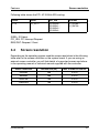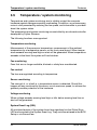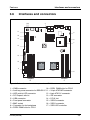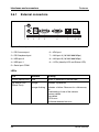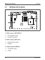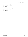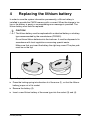
1
PRIMERGY
System board D2130
for RX220
Technical manual
Däschlein
Fujitsu Siemens Computers GmbH München
81730 Munich
e-mail: email: [email protected]
Tel.: (089) 61001-155
Fax: (++49) 700 / 372 00000
D2130 (RX220)
Sprachen: En
Edition September 2005
Comments… Suggestions… Corrections…
The User Documentation Department would like to
know your opinion of this manual. Your feedback helps
us optimize our documentation to suit your individual
needs.
Fax forms for sending us your comments are included in
the back of the manual.
There you will also find the addresses of the relevant
User Documentation Department.
Certified documentation
according to DIN EN ISO 9001:2000
To ensure a consistently high quality standard and
user-friendliness, this documentation was created to
meet the regulations of a quality management system
which complies with the requirements of the standard
DIN EN ISO 9001:2000.
cognitas. Gesellschaft für Technik-Dokumentation mbH
www.cognitas.de
Copyright and Trademarks
Copyright © 2005 Fujitsu Siemens Computers GmbH.
All rights reserved.
Delivery subject to availability; right of technical modifications reserved.
All hardware and software names used are trademarks of their respective manufacturers.
Contents
1
Introduction
2
2.1
2.2
2.3
Important notes . . .
Notes on safety . . . .
CE certificate . . . . .
Environment protection
.
.
.
.
.
.
.
.
.
.
.
.
.
.
.
.
.
.
.
.
.
.
.
.
.
.
.
.
.
.
.
.
.
.
.
.
.
.
.
.
.
.
.
.
.
.
.
.
.
.
.
.
.
.
.
.
.
.
.
.
.
.
.
.
. . 7
. . 7
. 10
. 11
3
3.1
3.2
3.3
3.3.1
3.3.2
3.4
3.5
3.6
3.6.1
3.7
Features . . . . . . . . . . . .
Overview . . . . . . . . . . . .
Main memory . . . . . . . . . .
Slots . . . . . . . . . . . . . . .
ISA bus resources . . . . . . . .
PCI resources . . . . . . . . . .
Screen resolution . . . . . . . .
Temperature / system monitoring
Interfaces and connectors . . . .
External connectors . . . . . . .
Settings with jumpers . . . . . .
.
.
.
.
.
.
.
.
.
.
.
.
.
.
.
.
.
.
.
.
.
.
.
.
.
.
.
.
.
.
.
.
.
.
.
.
.
.
.
.
.
.
.
.
.
.
.
.
.
.
.
.
.
.
.
.
.
.
.
.
.
.
.
.
.
.
.
.
.
.
.
.
.
.
.
.
.
.
.
.
.
.
.
.
.
.
.
.
.
.
.
.
.
.
.
.
.
.
.
.
.
.
.
.
.
.
.
.
.
.
.
.
.
.
.
.
.
.
.
.
.
.
.
.
.
.
.
.
.
.
.
.
.
.
.
.
.
.
.
.
.
.
.
.
.
.
.
.
.
.
.
.
.
.
.
.
.
.
.
.
.
.
.
.
.
.
.
.
.
.
.
.
.
.
.
.
13
13
16
18
19
20
21
22
23
24
26
4
Replacing the lithium battery . . . . . . . . . . . . . . . . .
29
Abbreviations . . . . . . . . . . . . . . . . . . . . . . . . . . . . . . .
31
D2130 (RX220)
. . . . . . . . . . . . . . . . . . . . . . . . . . . 5
.
.
.
.
.
.
.
.
.
.
.
.
.
.
.
.
1
Introduction
This technical manual describes the system board D2130, which can be
equipped with one or two AMD Opteron™/Dual Core Opteron™ processors.
Further information about drivers is provided in the readme files on the hard
disk, on the supplied "ServerSupport" or "ServerStart" CDs.
You will find further information in the BIOS description "D2130 Setup Utility for
RX220".
Notational conventions
The meanings of the symbols and fonts used in this manual are as follows:
italics
indicates commands, menu items, file and path
names or software programs
fixed font
indicate system output on the monitor
semi-bold fixed
font
indicates values to be entered through the keyboard
[Key symbol]
indicates keys according to their representation on the
keyboard
If capital letters are to be entered explicitly, then the
Shift key is shown, e.g. [SHIFT] - [A] for A.
If two keys need to be pressed at the same time, then
this is shown by placing a hyphen between the two key
symbols.
“quotation marks”
indicates names and terms that are being emphasized.
Ê
indicates an operation that to be performed
V CAUTION!
I
indicates warnings, which, if ignored, will endanger
your health, destroy the system or lead to the loss of
data.
indicates additional information, notes and tips
Table 1: Notational conventions
D2130 (RX220)
5
2
Important notes
In this chapter you will find essential information regarding safety when working
with your server.
V CAUTION!
With the system board installed you must open the system to access the
system board. How to dismantle and reassemble the system is described
in the Options Guide accompanying your system.
2.1
Notes on safety
V CAUTION!
●
The actions described in these instructions should only be performed
by authorized, qualified personnel. Equipment repairs should only be
performed by qualified staff. Any failure to observe the guidelines in
this manual, and any unauthorized openings and improper repairs
could expose the user to risks (electric shock, fire hazards) and could
also damage the equipment. Please note that any unauthorized
openings of the device will result in the invalidation of the warranty
and exclusion from all liability.
●
Transport the device only in the antistatic original packaging or in
packaging that protects it from knocks and jolts.
●
Only install expansions that are allowed for the system board. If you
install other expansions, you may damage the requirements and rules
governing safety and electromagnetic compatibility or your system.
Information on which system expansions are suitable can be
obtained from the customer service centre or your sales outlet.
●
The warranty expires if the device is damaged during the installation
or replacement of system expansions.
D2130 (RX220)
7
Notes on safety
V
Important notes
●
Components can become very hot during operation. Ensure you do
not touch components when making extensions to the system board.
There is a danger of burns!
●
Transmission lines to peripheral devices must be adequately
shielded.
●
To the LAN wiring the requirements apply in accordance with the
standards EN 50173 and EN 50174-1/2. As minimum requirement
the use of a protected LAN line of category 5 for 10/100 MBps
Ethernet, and/or of category 5e for Gigabit Ethernet is considered.
The requirements of the specification ISO/IEC 11801 are to be
considered.
●
Never connect or disconnect data transmission lines during a storm
(lightning hazard).
Batteries
V CAUTION!
●
Incorrect replacement of lithium battery may lead to a risk of
explosion. The batteries may only be replaced with identical batteries
or with a type recommended by the manufacturer.
It is essential to observe the instructions on page 29.
8
D2130 (RX220)
Important notes
Notes on safety
Modules with electrostatic-sensitive components
Systems and components that might be damaged by electrostatic discharge
(ESD) are marked with the following label:
Figure 1: ESD label
When you handle components fitted with ESDs, you must observe the following
points under all circumstances:
●
You must always discharge yourself of static charges (e.g. by touching a
grounded object) before working.
●
The equipment and tools you use must be free of static charges.
●
Remove the power plug from the power socket before inserting or removing
boards containing ESDs.
●
Always hold boards with ESDs by their edges.
●
Never touch pins or conductors on boards fitted with ESDs.
●
Use a grounding cable designed for this purpose to connect yourself to the
system unit as you install/deinstall the board.
●
Place all components on a static-safe base.
I You will find a detailed description for handling ESD components in the
relevant European or international standards (EN 61340-5-1,
ANSI/ESD S20.20).
D2130 (RX220)
9
CE certificate
Important notes
Notes about boards
●
During installation/deinstallation of the system board, observe the specific
instructions described in the service manual for the server.
●
Remove the plug from the mains outlet so that system and system board are
totally disconnected from the mains voltage.
●
To prevent damage to the system board, the components and conductors on
it, please take great care when you insert or remove boards. Take great care
to ensure that extension boards are slotted in straight, without damaging
components or conductors on the system board, or any other components,
for example EMI spring contacts
●
Be careful with the locking mechanisms (catches, centring pins etc.) when
you replace the system board or components on it, for example memory
modules or processors.
●
Never use sharp objects (screwdrivers) for leverage.
2.2
CE certificate
The shipped version of this board complies with the requirements
of the EEC directive 89/336/EEC "Electromagnetic compatibility".
Compliance was tested in a typical PRIMERGY configuration.
10
D2130 (RX220)
Important notes
2.3
Environment protection
Environment protection
Environmentally-friendly product design and development
This product has been designed in accordance with the Fujitsu Siemens
Computers standard for “environmentally friendly product design and development”. This means that key factors such as durability, selection and labeling
of materials, emissions, packaging, ease of disassembly and recycling have
been taken into account.
This saves resources and thus reduces the harm done to the environment.
Notes on saving energy
Devices that do not have to be on permanently should not be switched on until
they need to be used and should be switched off during long breaks and on
completion of work
Notes on packaging
Please do not throw away the packaging. You may need it later for transporting
your system unit. If possible, the device should only be transported in its original
packaging.
Notes on dealing with consumables
Please dispose of printer consumables and batteries in accordance with local
government regulations.
Do not throw batteries and accumulators into the household waste. They must
be disposed of in accordance with local regulations concerning special waste.
All batteries containing pollutants are marked with a symbol (a crossed-out
rubbish bin on wheels). In addition, the marking is provided with the chemical
symbol of the heavy metal decisive for the classification as a pollutant:
Cd Cadmium
Hg Mercury
Pb Lead
D2130 (RX220)
11
Environment protection
Important notes
Notes on labeling plastic housing parts
Please avoid attaching your own labels to plastic housing parts wherever
possible, since this makes it difficult to recycle them.
Returning, recycling and disposal
The device may not be disposed of with household rubbish. This
appliance is labelled in accordance with European Directive
2002/96/EC concerning used electrical and electronic appliances
(waste electrical and electronic equipment - WEEE).
The guideline determines the framework for the return and recycling
of used appliances as applicable throughout the EU. To return your
used device, please use the return and collection systems available
to you. You will find further information on this at www.fujitsusiemens.com/recycling.
For details on take-back and reuse of devices and consumables within Europe,
see the manual „Returning used devices“ or contact your Fujitsu Siemens
Computers branch office/subsidiary or our recycling center in Paderborn:
Fujitsu Siemens Computers
Recycling Center
D-33106 Paderborn
Germany
Tel.
+49 5251 8 18010
Fax
+49 5251 8 18015
Internet: www.fujitsu-siemens.com/recycling
12
D2130 (RX220)
3
Features
3.1
Overview
Processors
– 1 or 2 x AMD Opteron™/Dual Core Opteron™ processors
– 2 processor sockets 940 for AMD Opteron™/Dual Core Opteron™
processors with 2.0 GT/ 1.6 GT HyperTransport bandwidth
Main memory
– 8 slots for main memory DDR1/400 MHz (registered),
SDRAM memory modules,
dual channel with 2 modules per channel with 512 MB, 1 and 2 Gbyte
– maximum 16 Gbyte of memory
– ECC multiple bit error detection and single bit error correction
– memory scrubbing function
Chips on the system board
–
–
–
–
–
–
–
ServerWorks HT-2000 (Northbridge)
ServerWorks HT-1000 (Southbridge)
2 embedded dual Broadcom Gigabit LAN controllers
VGA controller (ATI Radeon 7000M) onboard with 16 MB SDRAM memory
SATA controller Promise PDC20319u
Super I/O controller (NS PC87417)
Flash EPROM for:
– BIOS
– LAN
– Server Management (SM)
– server management with BMC (FSC System)
– thermal and system management controller (ADM1026)
D2130 (RX220)
13
Overview
Features
Internal connectors
–
–
–
–
–
–
–
–
–
–
–
–
–
panel connector to front panel
1 IDE connector (CD-ROM/DVD-ROM)
Baseboard Management connector (for BMC)
USB connector
HDD activity connector
IPMB connector
2 Serial ATA connectors
auxiliary power connector for FSC RSBS2-LP card
8-pin ATX 12V connector
24-pin ATX power connector
battery holder
panel connector to fan backplane
connectors for PWM fans (Puls Wide modulation)
External connectors
–
–
–
–
–
1 serial port (COM1) for system and BMC (shared)
2 PS/2 interfaces for keyboard and mouse
2 USB 2.0 ports with 480 Mbits/s
1 VGA port
2 LAN (RJ-45) ports
Slots
– 1 x PCI-X 133 MHz/64 Bits 184P (PCI-X 1.0)
– 1 x PCI Express x8 slot 98P (PCI Express 1.0a)
14
D2130 (RX220)
Features
Overview
BIOS features
–
–
–
–
–
–
–
–
–
AMI BIOS
8 Mb
Special Hardware write protection
Standards
– Green
– PnP
– DMI
– WfM 2.0
– ACPI 2.0a
– SMBIOS 2.3
USB Boot device
– FDD
– ZIP
– HDD
– CD
– USB stick
HDT support
Optional ROM for LAN x 2
Shadow RAM in C, D, E segment with 4 KB alignment
Console redirection support
Environmental protection
Battery in holder
Form factor
E-ATX (SSI) 12.4 x 13 in.
D2130 (RX220)
15
Main memory
3.2
Features
Main memory
The system board supports up to 16 Gbyte main memory. Eight slots (four
memory banks with two slots each) are available for the main memory. Each
memory bank can be populated with two 512 Mbyte, 1 Gbyte or 2 Gbyte registered DDR1/400 MHz (PC-3200) memory modules.
CPU1
DIMM_2B
DIMM_1B
CPU2
DIMM_2A
DIMM_1A
DIMM_3A
DIMM_4A
DIMM_4B
DIMM_3B
ECC with memory scrubbing and with the Single Device Data Correction
(SDDC) function is supported.
Figure 2: Main memory
Module population
– The memory modules have to be populated in pairs.
– Each pair must consist of identical memory modules.
– The module capacity between pairs can differ: for example pair 1A/1B can
be populated with two 512 Mbyte modules and pair 2A/2B with two 1 Gbyte
modules.
16
D2130 (RX220)
Features
Main memory
Following table shows the possible module population:
X = populated
- = empty
For one CPU:
Memory
bank
1
2
1
2
DIMM
no.
color
DIMM
_1A
blue
DIMM
_2A
black
DIMM
_1B
blue
DIMM
_2B
black
DIMM
_3A
blue
DIMM
_4A
black
DIMM
_3B
blue
DIMM
_4B
black
Population
with
2 DIMMs
X
-
X
-
-
-
-
-
Population
with
4 DIMMs
X
X
X
X
-
-
-
-
For two CPUs:
Memory
bank
1
3
1
3
2
4
2
4
DIMM
no.
color
DIMM
_1A
blue
DIMM
_2A
black
DIMM
_1B
blue
DIMM
_2B
black
DIMM
_3A
blue
DIMM
_4A
black
DIMM
_3B
blue
DIMM
_4B
black
Population
with
2 DIMMs
X
-
X
-
-
-
-
-
Population
with
4 DIMMs
X
-
X
-
X
-
X
-
Population
with
6 DIMMs
X
X
X
X
X
-
X
-
Population
with
8 DIMMs
X
X
X
X
X
X
X
X
D2130 (RX220)
17
Slots
3.3
Features
Slots
1
2
Figure 3: Slots
PCI slots
The following table shows an overview of the slots:
18
Slot
64 bit/
32 bit
Frequency Description
in MHz
1
8x
100
8X PCI Express
2
64 bit
133
64-Bit PCI bus slot, full size or low profile
D2130 (RX220)
Features
3.3.1
Slots
ISA bus resources
Device
Timer
IRQ
Address
0
040-043
Keyboard
1
060,064
Serial port COM1
4
3F8-3FF
Real-time clock (RTC)
8
070-071
Microsoft ACPI-compliant
9
Mouse controller
12
Numeric processor
13
0F0-0FE
IDE controller (primary)
14
1F0-1F7, 3F6
DMA
"IRQ" = interrupt assigned as shipped
"Address" = this address can be used for your particular device
"Address" = this DMA can be used for your particular device
Default settings are shown in bold print
D2130 (RX220)
19
Slots
3.3.2
Features
PCI resources
PCI IRQ Line x - Assignment of the PCI interrupts
PCI IRQ Line x defines which ISA interrupts are used for the PCI-X and PCI
Express slots.
If you select Auto in the BIOS setup, the interrupts are assigned automatically
and no further settings are required.
Multifunctional PCI boards or boards with an integrated PCI-to-PCI bridge can
use several PCI interrupts (INTA#, INTB#, INTC#, INTD#). Monofunctional PCI
boards (default) only use one PCI interrupt (INTA#) per PCI slot.
The PCI interrupts INTA#, INTB#, INTC# and INTD# are available for each PCI
slot.
The same interrupt can be assigned simultaneously to several PCI boards. You
should avoid this condition due to reduced performance.
If you use a setting other than Auto, the Plug&Play functionality of the system
BIOS for the corresponding PCI boards is deactivated.
Auto
The PCI interrupts are assigned automatically in accordance with
the Plug&Play guidelines.
Disabled
No ISA interrupt is assigned to the PCI interrupt.
3, 4, 5, 7, 9, 11, 12, 14, 15
The selected ISA interrupt is assigned to the PCI interrupt. You
may not select an ISA interrupt that is used by a component on
the system board (e.g. controller) or an ISA board.
Following table shows the PCI IRQ routing:
Device
IDSEL
PCI_IRQ
REQ/GNT
VGA/Radeon
7000M
P3_AD21
PCIIRQ#8
P3REQ#0 /
P3GNT#0
20
D2130 (RX220)
Features
Screen resolution
Following table shows the PCI -X133 MHz IRQ routing:
Device
IDSEL
PCI_IRQ
REQ/GNT
PCI-X
P2_AD17
PCIIRQ#0 /
PCIIRQ#1 /
PCIIRQ#2 /
PCIIRQ#3
P2_REQ#0 /
P2_GNT#0
IDSEL: ID Select
PCI_IRQ: PCI Interrupt Request
REQ/GNT: Request / Grant
3.4
Screen resolution
Depending on the operating system used the screen resolutions in the following
table refer to the screen controller on the system board. If you are using an
external screen controller, you will find details of supported screen resolutions
in the operating manual or technical manual supplied with the controller.
Screen resolution
Refresh rate (Hz)
Max. number of colours
640x480
200
4.29 G
800x600
200
4.29 G
1024x768
160
4.29 G
1280x1024
100
4.29 G
D2130 (RX220)
21
Temperature / system monitoring
3.5
Features
Temperature / system monitoring
Temperature and system monitoring aim to reliably protect the computer
hardware against damage caused by overheating. In addition, any unnecessary
noise is also prevented by reducing the fan speed, and information is provided
about the system status.
The temperature and system monitoring are controlled by an onboard controller
developed by Fujitsu Siemens.
The following functions are supported:
Temperature monitoring
Measurement of the processor temperature, measurement of the ambient
temperature by a temperature sensor on the front panel board. When temperature exceeds warning level high an alert will be generated. When temperature
exceeds critical level the system will be shutdown.
Fan monitoring
Fans that are no longer available, blocked or sticky fans are detected.
Fan control
The fans are regulated according to temperature.
Sensor monitoring
The removal of, or a fault in, a temperature sensor is detected. Should this
happen all fans monitored by this sensor run at maximum speed, to achieve the
greatest possible protection of the hardware.
Voltage monitoring
When voltage exceeds warning level high or falls below warning level low an
alert will be generated.
System Event Log (SEL)
All monitored events of the system board are signalised via the Global Error
LED and recorded in the System Event Log. They could be retrieved in the BIOS
Setup or via ServerView.
22
D2130 (RX220)
Features
3.6
Interfaces and connectors
Interfaces and connectors
1 23
4
17
5
16
15
6
7
14
13
12
11
CPU2
CPU1
8
9
10
Figure 4: Schematic overview of the system board D2130
1=
2=
3=
4=
5=
6=
7=
8=
9=
IPMB connector
Auxiliary power connector for RSB S2 LP
HDD activity LED connector
PCI Express x8 slot
USB connector
Front panel connector
BMC socket
Connector for fan backplane
DDR1 DIMM slots for CPU1
D2130 (RX220)
10 = DDR1 DIMM slots for CPU2
11 = 24-pin ATXPWR connector
12 = 8-pin ATX12V connector
13 = IDE connector
14 = PCI-X slot
15 = SATA2 connector
16 = SATA1 connector
17 = SATA LED controller
23
Interfaces and connectors
3.6.1
Features
External connectors
1
2
3
4
5
6
7
8
9
Figure 5: External ports of the system board D2130
1 = PS/2 mouse port
6 = VGA port
2 = PS/2 keyboard port
7 = LAN port A (10/100/1000 MBps)
3 = USB port 0
8 = LAN port B (10/100/1000 MBps)
4 = USB port 1
9 = LEDs (Identify-LED and Status-LED)
5 = Serial port COM1
LEDs
LED
Indicator
Meaning
bottom: Identify-LED blue
server is identified via ServerView
top: Status-LED
(Global Error)
orange
indicates a prefailure
orange flashing
indicates a failure. Reasons for a failure may
be:
- overheating of one of the sensors
- sensor defect
- fan defect
- CPU error
- software detected an error
24
D2130 (RX220)
Features
Interfaces and connectors
LAN ports
On this system board you will find two LAN ports on the rear panel. The dual
embedded Broadcom Gigabit LAN controllers support transfer rates of 10
Mbit/s, 100 Mbit/s and 1 Gbit/s. The LAN controller supports WOL function
through Magic Packet™.
The LAN controller connectors are equipped with two LEDs (light emitting
diode). The left hand LED indicates the activity, the right hand LED is without
function.
2
1
Figure 6: LAN port
1
LAN link/aktivity
green
on
LAN connection
off
no LAN connection
flashing LAN transfer
2
no function
D2130 (RX220)
25
Settings with jumpers
3.7
Features
Settings with jumpers
Figure 7: Position of the jumpers
1 = BIOS recovery - (RECOVERY1)
1-2
Normal (default setting)
2-3
Force BIOS recovery
2 = SATA controller (SATA_EN1)
1-2
Enabled (default setting)
2-3
Disabled
3 = Keyboard power (KBPWR1)
1-2
+5V (default setting)
2-3
+5VSB
26
D2130 (RX220)
Features
Settings with jumpers
4 = VGA controller (VGA_EN1)
1-2
Enabled (default setting)
2-3
Disabled
5 = Clear CMOS / RTC (CLRTC1)
1-2
Normal (default setting)
2-3
Clear RTC
D2130 (RX220)
27
4
Replacing the lithium battery
In order to save the system information permanently, a lithium battery is
installed to provide the CMOS-memory with a current. When the charge is too
low or the battery is empty, a corresponding error message is provided. The
lithium battery must then be replaced.
V CAUTION!
The lithium battery must be replaced with an identical battery or a battery
type recommended by the manufacturer (CR2032).
Do not throw lithium batteries into the trashcan. It must be disposed of in
accordance with local regulations concerning special waste.
Make sure that you insert the battery the right way round. The plus pole
must be on the top!
Figure 8: Replacing the lithium battery
Ê Press the locking spring into direction of of the arrow (1), so that the lithiumbattery jumps out of its socket.
Ê Remove the battery (2).
Ê Insert a new lithium battery of the same type into the socket (3) and (4).
D2130 (RX220)
29
Abbreviations
The technical terms and abbreviations given below represent only a selection of
the full list of common technical terms and abbreviations.
Not all technical terms and abbreviations listed here are valid for the described
system board.
AC
Alternating Current
ACPI
Advanced Configuration and Power management Interface
ANSI
American National Standards Institute
ASR&R
Automatic Server Recovery and Restart
ATA
Advanced Technology Attachment
BBU
Battery Backup Unit
BIOS
Basic Input Output System
BMC
Baseboard Management Controller
CMOS
Complementary Metal Oxide Semiconductor
COM
COMmunication port
CPU
Central Processing Unit
D2130 (RX220)
31
Abbreviations
DDR
Double Data Rate
DIMM
Dual In-line Memory Module
DIP
Dual In-line Package
DMI
Desktop Management Interface
DRAM
Dynamic Random Access Memory
ECC
Error Correction Code
EEPROM
Electrical Erasable Programmable Read Only Memory
EFI
Extensible Firmware Interface
EGB
Elektrostatisch gefährdete Bauteile
EMI
Electromagnetic interference
EMRL
Embedded RAID Logic
EMV
Elektromagnetische Verträglichkeit (electromagnetic compatibility)
EPROM
Erasable Programmable Read Only Memory
ESD
ElectroStatic Discharge (elektrostatische Entladung)
32
D2130 (RX220)
Abbreviations
EVRD
Enterprise VRD
HPC
Hotplug Controller
FPC
Front Panel Controller
FRU
Field Replaceable Unit
FSB
Front Side Bus
ICE
In Circuit Emulation
IDE
Integrated (intelligent) Drive Electronics
IEC
International Electrotechnical Commission
IME
Integrated Mirroring Enhanced
IOOP
Intelligent Organisation Of PCI
IPMB
Intelligent Platform Management Bus
IPMI
Intelligent Platform Management Interface
ISO
International Organisation for Standardisation
LAN
Local Area Network
D2130 (RX220)
33
Abbreviations
LED
Light Emitting Diode
MPS
Multi Processor Specification
NMI
Non Maskable Interrupt
OEM
Original Equipment Manufacturer
OHCI
Open Host Controller Interface
OS
Operating System
PCI
Peripheral Components Interconnect
PDA
Prefailure Detection and Analyzing
PIO
Programmed Input Output
PDB
Power Distribution Board
PLD
Programmable Logic Device
PS(U)
Power Supply (Unit)
PWM
Pulse Wide Modulation
PXE
Preboot eXecution Environment
34
D2130 (RX220)
Abbreviations
RAID
Redundant Array of Inexpensive Disks
RoHS
Restriction of the Use of Certain Hazardous Substances (Waste from
Electric and Electronic Equipment, EU Directive)
RoMB
RAID on Motherboard
RSB
Remote Service Board
RST
ReSeT
RTC
Real Time Clock
SCSI
Small Computer Systems Interface
SDDC
Single Device Data Correction
SDRAM
Synchronous Dynamic Random Access Memory
SEL
System Event Log
SHDG
Server Hardware Design Guide
SMB
System Management Bus
SMM
Server Management Mode
SMP
Symmetrical Multi Processing
D2130 (RX220)
35
Abbreviations
UHCI
Unified Host Controller Interface
USB
Universal Serial Bus
VGA
Video Graphics Adapter
VRD
Voltage Regulator Down
VRM
Voltage Regulator Module
WEEE
Waste from Electric and Electronic Equipment (EU Directive)
WfM
Wired for Management
WOL
Wake up On LAN
36
D2130 (RX220)
Fujitsu Siemens Computers GmbH
User Documentation
81730 Munich
Germany
Fax: (++49) 700 / 372 00000
email: [email protected]
http://manuals.fujitsu-siemens.com
Submitted by
✁
Comments on System board D2130 for RX220
Technical manual
D2130 (RX220)
Comments
Suggestions
Corrections
Fujitsu Siemens Computers GmbH
User Documentation
81730 Munich
Germany
Fax: (++49) 700 / 372 00000
email: [email protected]
http://manuals.fujitsu-siemens.com
Submitted by
✁
Comments on System board D2130 for RX220
Technical manual
D2130 (RX220)
Comments
Suggestions
Corrections
Information on this document
On April 1, 2009, Fujitsu became the sole owner of Fujitsu Siemens Computers. This new subsidiary of Fujitsu has been renamed Fujitsu Technology Solutions.
This document from the document archive refers to a product version which
was released a considerable time ago or which is no longer marketed.
Please note that all company references and copyrights in this document have
been legally transferred to Fujitsu Technology Solutions.
Contact and support addresses will now be offered by Fujitsu Technology Solutions and have the format …@ts.fujitsu.com.
The Internet pages of Fujitsu Technology Solutions are available at
http://ts.fujitsu.com/...
and the user documentation at http://manuals.ts.fujitsu.com.
Copyright Fujitsu Technology Solutions, 2009
Hinweise zum vorliegenden Dokument
Zum 1. April 2009 ist Fujitsu Siemens Computers in den alleinigen Besitz von
Fujitsu übergegangen. Diese neue Tochtergesellschaft von Fujitsu trägt seitdem den Namen Fujitsu Technology Solutions.
Das vorliegende Dokument aus dem Dokumentenarchiv bezieht sich auf eine
bereits vor längerer Zeit freigegebene oder nicht mehr im Vertrieb befindliche
Produktversion.
Bitte beachten Sie, dass alle Firmenbezüge und Copyrights im vorliegenden
Dokument rechtlich auf Fujitsu Technology Solutions übergegangen sind.
Kontakt- und Supportadressen werden nun von Fujitsu Technology Solutions
angeboten und haben die Form …@ts.fujitsu.com.
Die Internetseiten von Fujitsu Technology Solutions finden Sie unter
http://de.ts.fujitsu.com/..., und unter http://manuals.ts.fujitsu.com finden Sie die
Benutzerdokumentation.
Copyright Fujitsu Technology Solutions, 2009