1
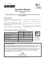
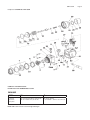
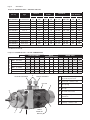
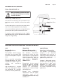
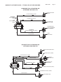
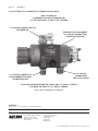
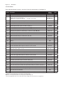
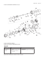
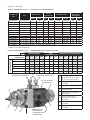
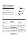
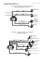
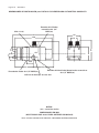
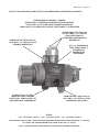
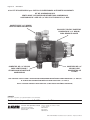
Service Bulletin SB-2-586-H Replaces SB-2-586-G OPERATION MANUAL COMPACT-I — AUTOMATIC SPRAY GUN CONVENTIONAL, TRANS-TECH & HVLP Air Cap Selection Determines Spray Technology English: Pages 1-14 Español: Páginas 15-28 Replacement Parts Ordering Information SEE PAGE 4 Explanation of Conventional, Trans-Tech and HVLP SEE PAGE 9 Complete Spray Gun Assembly Ordering Information SEE PAGE 10 Installation Details SEE PAGES 11, 12, 13, 14 Page 2 SB-2-586-H Operation Manual Compact-I Automatic Spraygun Important Read and follow all instructions and Safety Precautions before using this equipment CHARACTERISTICS This automatic spray gun complies to ATEX regulations 94/9/EC, protection level II 2 G X, suitable to use in Zones 1 & 2. This Compact-I is a production spray gun suitable for use with automatic and semi-automatic machine in conventional, HVLP or Trans-Tech application. (See page 9 for application details.) To handle a wide range of coating materials the material passages are manufactured from high grade stainless steel. Several needles are available with plastic tips. Fluid tips and needles are available in high grade stainless steel. Pressure feed material supply can be re-circulating or direct. The needle adjustment knob has 18 ratchet positions (per one revolution of the knob) which allows fine and accurate fluid flow control. SPECIFICATIONS & MATERIALS OF CONSTRUCTION Thread Pressure Fluid inlet & recirculation “P” & "R" 1/4" BSPP(F) Max 7 Bars (100 psi) Air inlet (Atom & Fan) “A” & “F” 1/4" BSPP(F) Max 7 Bars (100 psi) Cylinder/trigger “Cyl” 1/8" BSPP(F) 4 to 7 Bars (60-100 psi) Maximum temperature in use 40° C (104° F) Spray gun weight 656 gms (1.44 lbs) Gun body Aluminium hard anodized Tip / Needle / Spray head Stainless steel 303 CA PROP 65 PROP 65 WARNING WARNING: This product contains chemicals known to the State of California to cause cancer and birth defects or other reproductive harm. EC Declaration of Conformity We, Finishing Brands UK, Ringwood Rd, Bournemouth, Dorset, BH11 9LH, UK, as the manufacturer of the Spray gun model Compact-I, declare, under our sole responsibility that the equipment to which this document relates is in conformity with the following standards or other normative documents: BS EN 292-1 PARTS 1 & 2: 1991, BS EN 1953: 1999; and thereby conform to the protection requirements of Council Directive 98/37/EEC relating to Machinery Safety Directive, and; EN 13463-1:2001, council Directive 94/9/EC relating to Equipment and Protective Systems intended for use in Potentially Explosive Atmospheres protection level II 2 G X. D. Smith, General Manager 12th February 2014 DeVilbiss reserves the right to modify equipment specification without prior notice. SB-2-586-H Page 3 SAFETY WARNINGS FIRE AND EXPLOSION Solvents and coating materials can be highly flammable or combustible when sprayed. ALWAYS refer to the coating material supplier's instructions and MSDS sheets before using this equipment. Users must comply with all local and national codes of practice and insurance company requirements governing ventilation, fire precautions, operation and house-keeping of working areas. This equipment, as supplied, is NOT suitable for use with Halogenated Hydrocarbons. Static Electricity can be generated by fluid and/or air passing through hoses, by the spraying process and by cleaning non- conductive parts with cloths. To prevent ignition sources from static discharges, earth continuity must be maintained to the spray gun and other metallic equipment used. It is essential to use conductive air and/or fluid hoses. PERSONAL PROTECTIVE EQUIPMENT Toxic vapors – When sprayed, certain materials may be poisonous, create irritation or be otherwise harmful to health. Always read all labels, safety data sheets and follow any recommendations for the material before spraying. If In doubt, contact your material supplier. The use of respiratory protective equipment is recommended at all times. The type of equipment must be compatible with the material being sprayed. Always wear eye protection when spraying or cleaning the spray gun Gloves must be worn when spraying or cleaning the equipment. TRAINING Personnel should be given adequate training in the safe use of spraying equipment. MISUSE Never aim a spray gun at any part of the body. Never exceed the max. recommended safe working pressure for the equipment. The fitting of non-recommended or non-original spares may create hazards. Before cleaning or maintenance, all pressure must be relieved from the equipment. The product's metal parts can be cleaned using a gun-washing machine. However, this equipment should not be left inside gun-washing machines for prolonged periods of time. Certain selas and o-rings may not be solvent compatible. NOISE LEVELS The A-weighted sound level of spray guns may exceed 85 dB (A) depending on the set-up being used. Details of actual noise levels are available on request. It is recommended that ear protection is worn at all times when spraying. OPERATING Spray equipment using high pressures may be subject to recoil forces. Under certain circumstances, such forces could result in repetitive strain injury to the operator. Page 4 SB-2-586-H PARTS LIST For the arrangement of the parts, refer to the exploded view on page 5. Description Order Part Number Qty 1 Air cap and its retaining ring with seals. See chart on page 6. SP-100-xxx-K 1 2 Tip with air separator seal Ø 0.85 / 1.0 / 1.4 / 1.8 / 2.2 mm Air cap 591 Ø 0.5 for air cap 590 SP-200S-xx-K SP-259S-xx-K 1 4 Locator ring for indexed air cap SPA-112 1 5 Air separator ring (kit of 5 rings) SPA-27-K5* 1 6 Screw M4 x 25 (kit of 4 Torx 20 screws) S-14192-K4* 4 8 Spray head for Compact-I SPA-40 1 9 Packing seal (kit includes items 9 , 10, 11, 16a) SPK-115* 1 10 Sealing washer (kit includes items 9, 10, 11, 16a) SPK-115* 1 11 O-ring gasket (kit includes items 9, 10, 11 n , 16a) SPK-115* 2 12 Gun body for Compact-I SPA-1-CMAI-S 1 13 Air valve (fan and atomizing air) AGG-403 2 14 O-ring (kit includes items 14, 15a, 16) SPK-104* 1 15 Piston + o-ring (kit includes items 14, 15a, 15b, 16) SPA-6X-K* 1 15a O-ring (kit includes items 14, 15a, 16) SPK-104* 1 15b Piston REF. 1 Item 16 O-ring (kit includes items 14, 15a, 16) SPK-104* 1 16a O-ring (kit includes items 9, 10, 11, 16a) SPK-115* 1 17 Piston Spring (kit includes items 17, 22, 23, 24) SPK-105* 1 18 Stainless steel needle 0.5 / 0.85 / 1.0 / 1.4 / 1.8 / 2.2 mm Plastic tip needle 0.85 / 1.4 mm SPA-310-xx SPA-310P-xx 1 19 Housing SPA-3 1 20 Kit of ring and ball for ratchet (kit includes items 20, 21, 25) SPK-106* 1 21 Ring (kit includes items 20, 21, 25) SPK-106* 1 22 Needle spring (kit includes items 17, 22, 23, 24) SPK-105* 1 23 Spring cap (kit includes items 17, 22, 23, 24) SPK-105* 1 24 Spring washer (kit includes items 17, 22, 23, 24) SPK-105* 1 25 Adjusting knob (kit includes items 20, 21, 25) SPK-106* 1 27 Kit for air connection of remote control (includes "A" and "F" fittings) SPA-22-K2* 1 28 Gun mounting bar (kit includes items 28, 29, 31) SPK-110* 1 SPK-110* 1 REF. 1 SPK-110* 2 REF. 1 SPK-102-K* 1 29 Gun mounting bar nut (kit includes items 28, 29, 31) 30 Plug ¼" BSPP for spray gun without fluid recirculation 31 M5 hexagon socket head cap screw, length 8 (kit includes items 28, 29, 31) 32 Fluid insert plug 33 Kit of retaining ring with gasket (kit includes air cap ring and gaskets) *Spare parts must be ordered as part of replacement kits listed above. Item 9: Fluid packings only (10 pack) SPA-86-K10. n Item 11: Air gaskets only (10 pack) SPA-53-K10. See page 10 for additional adapter/fitting kits for air and fluid hoses. SB-2-586-H Compact-I AUTOMATIC SPRAY GUN COMPACT-I AUTOMATIC GUN EXAMPLE OF PART NUMBERING SYSTEM CMAI-85P CMAI 85 P Compact-I Automatic Spray Gun 85 = .85 mm Fluid Nozzle and Needle 00 = N o Fluid Nozzle, No Needle P = Plastic Needle – or no letter = S tainless Steel Needle NOTE: SPN-8 Torx wrench for item 6 shipped with gun. Page 5 Page 6 SB-2-586-H Compact-I AUTOMATIC GUN — AVAILABLE AIR CAPS Air cap Pressure at Inlet Air Flow Type SCFM l/min psi bar Pattern size @ 8" distance Fluid Flow oz/min ml/min in mm SP-100-430-K Conventional 12 340 50.7 3.5 6.7 - 9.5 200 - 280 7.9 200 SP-100-443-K Conventional 12.2 345 43.5 3.0 6.7 - 10.1 200 - 300 11.8 300 SP-100-497-K Conventional 18 510 50.7 3.5 6.7 - 20.2 200 - 600 15.0 380 SP-100-500R-K Round Spray 6.8 200 16.0 1.1 .6 - 5.0 20-150 1.6 40 SP-100-506-K HVLP 10.6 300 19 1.3 4.4 - 6.5 130 – 190 12 310 SP-100-507-K HVLP 19 385 40 1.4 4.4 - 6.5 130 – 190 10.6 270 SP-100-508-K HVLP 11 311 14 1.0 4.4 - 6.5 130 – 190 10 250 SP-100-510-K Trans-Tech 10 283 29 2.0 5.4 - 7.5 160 - 220 10.6 270 SP-100-513-K Trans-Tech 18.8 531 43.5 3.0 6.7 - 20.2 200 - 600 13.8 350 SP-100-522-K Trans-Tech 14.5 410 29 2.0 6.7 - 20.2 200 - 600 13.8 350 SP-100-590-K Trans-Tech 7.7 218 29 2.0 1.6 - 5.0 50 -150 6.0 150 SP-100-591-K Trans-Tech 12.3 350 29 2.0 1.7 - 5.1 50 -150 4.5 115 KK-5090-507 HVLP Test Kit – includes cap, gauge & tube Other test kits available: KK-5090-430, KK-5090-443, KK-5090-497, KK-5090-506, KK-5090-507, KK-5090-508, KK-5090-510, KK-5090-513, KK-5090-522, KK-5009-590 Compact-I AUTOMATIC GUN — AIR CAP COMBINATIONS CONVENTIONAL TYPE FLUID TIP SIZES AIR CAP MODEL NO. 430 443 497 HVLP 500R 506 507 TRANS-TECH 508 510 513 522 .020" (0.5 mm) .033" (0.85 mm) X X X X X .039" (1.0 mm) X X X X X X X X X X .055" (1.4 mm) X X X X X X X X X X .070" (1.8 mm) X X X X X X X X X .086" (2.2 mm) X X X X X X ATOM ADJUSTMENT E FAN ADJUSTMENT 590 591 X X X A Needle travel adjusting knob – 18 positions per 1 turn B Gun head – stainless steel C Air cap ring D Air cap E Air valve (fan / atom) F Spray gun body – anodized aluminum P Fluid inlet – stainless steel G Fluid tip – stainless steel CYL AIR A G F D C B P FAN & ATOM AIR SUPPLY SB-2-586-H Page 7 INSTALLATION Important: To ensure that this equipment reaches you in first class condition, protective coatings have been used. Flush the equipment through with appropriate solvent before use. Mount the spray gun using mounting stem ref.28 and secure it with nut ref.29. AIR AND FLUID HOSES See pages 11, 12, 13 and 14 for installation details. Use separate filtered regulated air supplies for atomizing and cylinder air. Connect the cylinder air ‘CYL AIR’ on top of the body via a control valve. For fast cylinder operation the control valve should be fitted as close to the gun as possible or an additional quick exhaust valve installed in the line. Attach atomizing air hose to the inlet threaded hole ‘FAN & ATOM AIR’ under the gun body. Recommended hose size up to 34 ft. (10 m) long: Atomization Air = 0.315 in. (8 mm) Cylinder Air = 0.236 in. (6 mm) Material = 0.315 in. (8 mm) Connect material hose(s) ‘P’ to the spray head. If material re-circulation is required, remove plugs (30) & (32). Fit standard connector (¼” BSPP) to the spray head. Important: The Spray gun must be grounded to dissipate any electrostatic charges which may be created by fluid or air flows. This can be achieved through the Spray gun mounting, or conductive air/fluid hoses. Electrical bond from the spray gun to earth should be checked with an ohmmeter. A resistance of less than 106 Ohms is recommended. SETTING STARTING UP 1. The ATOM ‘A’ air valve controls the atomizing air pressure FAN ‘F’ valve reduces the spray pattern size. To increase the pressure turn clockwise, to reduce turn counter-clockwise. 1. T urn the needle adjusting knob (25) clockwise until the needle is fully closed. 2. F luid flow can be adjusted with the rear ratchet knob, fluid flow is increased when you turn the knob counter-clockwise. 3. F or the arrangement of the parts, refer to the exploded view on page 5. 2. Turn the FAN ‘F’ and ATOM ‘A’ air valves (13) counter-clockwise to be full open. 3. U se the air cap chart above to set the air pressure at the air regulator to achieve recommended pressures above. 4. T urn the adjusting knob (25) counter clockwise to obtain the desired fluid flow. 5. T est spray. If the finish is too dry or fine, reduce the airflow by reducing the air inlet pressure or by screwing the valve ATOM ‘A’ (13) in clockwise, or increase the fluid flow using ratchet knob, rotating counter clockwise. Page 8 SB-2-586-H INSTALLATION (CONTINUED) START UP (continued) 6. If the finish is too wet, turn the ratchet knob (25) in clockwise to reduce the fluid flow, or reduce the fluid pressure. If the atomization is too coarse, increase inlet air pressure, or reduce fluid flow. 7. T he pattern size can be controlled by turning adjusting valve FAN ‘F’ (13) clockwise. 9. T he recommended spray distance is 6’’ to 8’’ (150-220 mm). 10. S pray edges first. Overlap each spray stroke a minimum of 50%. Move gun at a constant speed. 11. A lways turn off air and fluid supply and relieve pressure and clean down when gun is not in us. 8. T he spray pattern will give the best results when perpendicular to the target. MAINTENANCE PREVENTIVE MAINTENANCE Turn off air and coating supply and relieve pressure in the supply lines, or disconnect from airline and fluid line. 1. R emove air cap (1) and clean. If any of the holes in the cap are blocked with coating material use a toothpick to clean. Never use metal wire which could damage the cap and produce distorted spray patterns 2. E nsure the nozzle of the fluid tip (2) is clean and free from damage. Any build up of dried paint can distort the spray pattern. REPLACEMENT OF PARTS Turn off air and coating supply and relieve pressure in the supply lines, before any maintenance operation. TIP (2) & NEEDLE (18) Unscrew the adjusting needle knob (25) fully in counter-clockwise rotation, push the needle from the front of the spay gun, carefully so to avoid damage the needle end, then pull out the needle (18) from the back. If necessary, replace the needle and the tip, first screw the tip with its air separator ring (recommended torque between 9.5 to 12 Nm). Use gun lube to lubricate all the surface of the needle which will be in contact with the packing and o ring. Slide the needle into the spray gun from the back. Fit the needle springs with its plastic pad (22,23,24) and replace the needle adjusting knob (25). PACKING SEAL (9) Unscrew the air cap (1), tip (2) and its air separator ring (3). Unscrew the 4 screws (6) to disassemble the gun head (8). Remove the air cap (1) by unscrewing its retaining ring counter- clockwise, remove the index ring if it remains on the gun head (if fitted and used). Push back the two packing seals (9) using a 5.5 mm diameter rod from the front of the gun head. Clean the packing location hole carefully with water or solvent compatible with material being sprayed. Remove the tip (2) and its air separator ring (3) by unscrewing counter- clockwise with 10mm hexagonal spanner. Fit new packing seals (9) with "U" face towards the fluid passage. SB-2-586-H Page 9 REPLACEMENT OF PARTS (CONTINUED) FAN & ATOM AIR VALVE (13) Before assembling, check the air valve is in fully open position by unscrewing it counter-clockwise. PISTON (15), O RING (16) & (14) Unscrew the rear housing (19) at the back of the gun body counter clockwise, pull out the needle (18). Piston Assembly (ref.) Bent Nose Pliers (ref.) Use bent nose pliers so to pull out the piston which has a 12 mm internal groove for this purpose. It is recommended to replace the o-ring (14) into the gun body as soon you disassemble the Piston. If necessary, when replacing the piston, slightly lubricate the piston lip with petroleum jelly before fitting into the gun body. DEVILBISS SPRAY GUN TECHNOLOGY—APPLICATION DETAILS HVLP TRANS-TECH CONVENTIONAL Maintains Regulatory Compliance Maximum Efficiency with Environmental Responsibility Outperforms the Competition The DeVilbiss "HVLP" Compact gun allows you to maintain EPA compliance and produce a superb finish. The DeVilbiss "Trans-Tech" Compact gun utilizes the very latest advances in computational fluid dynamics. This results in superior atomization with the new DeVilbiss TRANSFERTECHNOLOGY. Built to provide outstanding coating atomization, the "HVLP" Compact can handle all types of solvent and waterborne materials. High performance is coupled with a gun body light in weight and designed for operator comfort to increase productivity. Exceptionally efficient material transfer for optimum coverage and paint usage is achieved with reduced air consumption, lowering your electrical needs and energy costs. Exceed your production requirements with the highest atomization levels at an accelerated application rate of up to 600cc/min. The DeVilbiss "Conventional" Compact is our Advanced Conventional gun and has a unique high capacity airflow with outstanding atomization to produce a superior result. Compact's Advanced Conven tional Air Caps make this gun the ideal performer in both small operations or high volume facilities, with the added bonus of instantly improved finishing productivity. Page 10 SB-2-586-H STANDARD SET-UPS AVAILABLE FOR COMPACT-I AUTOMATIC SPRAY GUN PART NUMBER DESCRIPTION CMAI-G05 COMPACT AUTO-I .5 MM, NO AIR CAP CMAI-G85 COMPACT AUTO-I .85 MM, NO AIR CAP CMAI-10 COMPACT AUTO-I 1.0 MM, NO AIR CAP CMAI-14 COMPACT AUTO-I 1.4 MM, NO AIR CAP CMAI-14P COMPACT AUTO-I 1.4 MM PLASTIC NEEDLE, NO AIR CAP CMAI-18 COMPACT AUTO-I 1.8 MM, NO AIR CAP NOTE: Air caps ordered separately. Refer to page 6 for air cap ordering information. COMPACT-I AUTOMATIC – HOSE FITTING KITS: 6-530 FLUID / AIR / FITTING KIT (for combined or separate fan/atomization—Push-to-Lok Connections) 6-532 FLUID / AIR FITTING KIT (for combined or separate fan/atomization—NPS connections) COMPACT-I AUTOMATIC GUN — TYPICAL AIR & FLUID DIAGRAMS SB-2-586-H Page 11 COMBINED FAN & ATOMIZING AIR (STANDARD GUN HOOK-UP) FLUID RETURN (IF USED) ATOMIZING ADJUSTMENT VALVE BACK PRESSURE VALVE CYLINDER AIR SUPPLY FAN ADJUSTMENT VALVE CYLINDER AIR VALVE (3 WAY) AIR REGULATOR (FAN & ATOMIZING AIR COMBINED) (COMBINED) FAN & ATOMIZING AIR SUPPLY FLUID SUPPLY FLUID REGULATOR SEPARATE FAN & ATOMIZING AIR (OPTIONAL GUN HOOK-UP) BACK PRESSURE VALVE FAN AIR VALVE (3 WAY) FLUID RETURN (IF USED) FAN AIR SUPPLY ATOMIZING AIR SUPPLY CYLINDER AIR SUPPLY FAN AIR REGULATOR ATOMIZING AIR REGULATOR ATOMIZING AIR VALVE (3 WAY) PLUG CYLINDER AIR VALVE (3 WAY) FLUID SUPPLY FLUID REGULATOR Page 12 SB-2-586-H INSTALLATION DIMENSIONS for COMPACT-I AUTOMATIC SPRAY GUN 1/8" BSPP (m) Cylinder Air Inlet M12-1.0 (2) 141 126 44 67 22 23 10 12 44 17.5 23.4 63 69.5 1/4" BSPP (m) Fluid Inlet 1/4" BSPP (m) Fan/Atomizing Air Inlet 12.8mm o / Mounting Hole DIMENSIONS IN MM (MULTIPLY BY .03937 TO OBTAIN INCHES) BSPP = BRITISH STRAIGHT PIPE PARALLEL SB-2-586-H Page 13 6-530 FITTING KIT for COMPACT-I AUTOMATIC SPRAY GUN PUSH-TO-LOCK CONNECTIONS SEPARATE FAN AND ATOMIZING AIR 6MM O.D. TUBE FOR CYLINDER AIR 8MM O.D. TUBE FOR FLUID, FAN AND ATOMIZING 8 MM O.D. x 1/4" BSPP(m) TUBE CONNECTIONS FOR SEPARATE FAN AND ATOMIZING AIR 6 MM O.D. x 1/8" BSPP(m) TUBE CONNECTION FOR CYLINDER AIR M12-1.0 FITTINGS FOR SEPARATE FAN AND ATOMIZING AIR 1/4" BSPP SCREW INSTALL TO PLUG COMBINED FAN AND ATOMIZING PORT 8 MM O.D. x 1/4" BSPP(m) TUBE CONNECTION FOR FLUID SUPPLY FLUID AND FAN/ATOMIZING AIR PORTS ARE 1/4" BSPP(f) THREAD CYLINDER AIR PORT IS 1/8" BSPP(f) THREAD BSPP = BRITISH STRAIGHT PIPE PARALLEL Page 14 SB-2-586-H 6-532 FITTING KIT for COMPACT-I AUTOMATIC SPRAY GUN NPS FITTINGS KIT COMBINED FAN AND ATOMIZING AIR 1/4" NPS AIR AND 3/8" NPS FLUID FITTINGS 1/4" NPS (M) CONNECTOR FOR CYLINDER AIR REMOVE PLUG AND INSERT 3/8" NPS (M) CONNECTION FOR RECIRCULATION 3/8" NPS (M) CONNECTION FOR FLUID SUPPLY 1/4" NPS (M) CONNECTOR FOR COMBINED FAN AND ATOMIZATION AIR FLUID AND FAN/ATOMIZING AIR PORTS ARE 1/4" BSPP(f) THREAD CYLINDER AIR PORT IS 1/8" BSPP(f) THREAD BSPP = BRITISH STRAIGHT PIPE PARALLEL WARRANTY This product is covered by DeVilbiss’ 1 Year Limited Warranty. DeVilbiss Sales and Service: www.devilbiss.com U.S.A./Canada Customer Service 195 Internationale Blvd. Glendale Heights, IL 60139 630-237-5000 Toll Free Customer Service and Technical Support 800-992-4657 Toll Free Fax 888-246-5732 2/14 ©2014 DeVilbiss All rights reserved. Printed in U.S.A. Boletín de mantenimiento SB-2-586-H Reemplaza al SB-2-586-G MANUAL DE OPERACIONES PISTOLA PULVERIZADORA AUTOMÁTICA COMPACT- I CONVENCIONAL, TEC-TRANS Y HVLP Selección casquillo de aire determina tecnología de pulverizadora English: Pages 1-14 Español: Páginas 15-28 Información para pedir piezas de reemplazo VER PÁGINA 18 Explicación de Convencional, Tec-Trans y HVLP VER PÁGINA 23 Información completa para pedir el conjunto de la pistola pulverizadora VER PÁGINA 24 Detalles de la instalación VER PÁGINAS 25, 26, 28, 29 Página 16 SB-2-586-H Manual de Operaciones Pistola pulverizadora automática Compact-I Importante Lea y siga todas las instrucciones y precauciones de seguridad antes de usar este equipo CARACTERÍSTICAS Esta pistola pulverizadora automática cumple con las regulaciones 94/9/CE de ATEX, nivel de protección II 2 G X, adecuada para uso en Zonas 1 y 2. Esta pistola modelo Compact-I es una pistola pulverizadora de producción adecuada para uso con máquinas automáticas y semiautomáticas en aplicaciones convencionales, HVLP o de tecnología de transferencia. (para detalles de aplicaciones ver página 23). Para funcionar con una amplia gama de materiales de recubrimiento los pasajes de material son fabricados de acero inoxidable de alta calidad. Varias agujas están disponibles con puntas de plástico. Están disponibles puntas hidráulicas y agujas en acero inoxidable de alta calidad. El suministro de materiales alimentado a presión puede ser recirculatorio o directo. La perilla de ajuste de la aguja tiene 18 posiciones de trinquete (por una revolución de la perilla) permite el control fino y preciso del caudal de flujo. ESPECIFICACIONES Y MATERIALES DE CONSTRUCCIÓN Rosca Presión Entrada de fluido y recirculación “P” y "R" 1/4" BSPP(F) Máx. 7 Bars (100 psi) Entrada de aire (atomizador y ventilador) “A” y “F” 1/4" BSPP(F) Máx. 7 Bars (100 psi) Cilindro/disparador “Cyl” 1/8" BSPP(F) de 4 a 7 Bars (60-100 psi) Temperatura máxima en uso 40° C (104° F) Peso de la pistola pulverizadora 656 g (1.44 lbs) Cuerpo de la pistola Aluminio duro anodizado Punta / aguja / boquilla pulverizadora Acero inoxidable 303 CA PROP 65 ADVERTENCIA PROP 65 ADVERTENCIA: Este producto contiene sustancias químicas que según información en poder del estado de California producen cáncer, defectos de nacimiento y otros daños al sistema reproductor. Declaración de conformidad de CE Nosotros, Finishing Brands UK, Ringwood Rd, Bournemouth, Dorset, BH11 9LH, UK, como los fabricantes de la Pistola pulverizadora modelo Compact-I, declaramos, bajo nuestra sola responsabilidad que el equipo al que se relaciona este documento cumple con las siguientes normas u otros documentos normativos: BS EN 292-1 PARTES 1 y 2: 1991, BS EN 1953: 1999; y por consiguiente cumple con los requisitos de protección de la Directiva del Consejo 98/37/CEE relacionada con la Directiva de Seguridad de Maquinarias, y; EN 13463-1:2001, la Directiva del Consejo 94/9/CE relacionada con Equipos y Sistemas Protectores destinados para uso en Atmósferas Potencialmente Explosivas nivel de protección II 2 G X. D. Smith, Gerente General 12 de febrero de 2014 DeVilbiss se reserva el derecho de modificar la especificación del equipo sin previo aviso. SB-2-586-H Página 17 ADVERTENCIAS DE SEGURIDAD INCENDIO Y EXPLOSIÓN Los disolventes y los materiales de recubrimiento pueden ser altamente inflamables o combustibles al ser rociados. Consulte SIEMPRE las instrucciones del proveedor del material de recubrimiento y la hoja de datos de seguridad de los materiales (MSDS) antes de usar este equipo. Los usuarios deben cumplir con todos los códigos locales y nacionales de práctica y los requisitos de la compañía aseguradora que rigen la ventilación, precauciones para casos de incendio, operación y limpieza de las áreas de trabajo. Este equipo, como se provee, NO es adecuado para uso con Hidrocarburos Halogenados. La electricidad estática puede ser generada por el fluido y/o el aire que pasa por las mangueras, por el proceso de rociado y limpiando con paños las partes no conductoras. Para prevenir la ignición por descargas estáticas, se debe mantener la continuidad de la conexión a tierra hacia la pistola pulverizadora y otros equipos metálicos utilizados. Es esencial utilizar aire conductor y/o mangueras de fluidos. EQUIPO DE PROTECCIÓN PERSONAL Vapores tóxicos – Al ser rociados, ciertos materiales pueden ser tóxicos, producir irritación o perjudicar la salud. Lea siempre todas las etiquetas, hojas de datos de seguridad y siga todas las recomendaciones para los materiales antes de rociar. Si tiene duda, póngase en contacto con su proveedor de materiales. Se recomienda usar todo el tiempo equipo de protección para la respiración. El tipo de equipo tiene que ser compatible con el material que está siendo rociado. Use siempre protección para los ojos al rociar o limpiar la pistola pulverizadora. Se deben usar guantes al rociar o limpiar el equipo. CAPACITACIÓN El personal tiene que recibir la capacitación adecuada en el uso sin riesgos del equipo pulverizador. USO INDEBIDO Nunca apunte la pistola pulverizadora a una parte del cuerpo. Nunca sobrepase la presión de trabajo segura máxima recomendada para el equipo. El uso de piezas de reemplazo no recomendadas o no originales puede resultar peligroso. Antes de limpiar o dar mantenimiento, se debe eliminar toda la presión del equipo. Las partes metálicas del producto se pueden limpiar usando una máquina para limpiar pistolas. Sin embargo, no se debe dejar este equipo dentro de máquinas para limpiar pistolas por períodos prolongados. Ciertos sellos y las juntas tóricas podrían no ser compatibles con el disolvente. NIVELES DE RUIDO El nivel de ruido con ponderación A de las pistolas pulverizadoras puede sobrepasar los 85 dB (A) dependiendo de la configuración que se esté usando. Los detalles de los niveles de ruido reales están disponibles previa solicitud. Se recomienda el uso de protección para los oídos siempre que se rocíe. OPERACIÓN Los equipos pulverizadores que usan presiones altas pueden generar fuerzas de reacción. Bajo ciertas circunstancias, tales fuerzas pueden producir lesiones repetitivas por tensión en el operador. Página 18 SB-2-586-H LISTA DE PIEZAS Para la disposición de las piezas, consulte la vista de componentes en la página 19. Artículo Descripción Número de pieza Cant. 1 Casquillo de aire y su anillo de retención con sellos. Ver tabla en la página 20. SP-100-xxx-K 1 2 Punta con sello del separador de aire Ø 0.85 / 1.0 / 1.4 / 1.8 / 2.2 mm Ø 0.5 para el casquillo de aire 590 Casquillo de aire 591 SP-200S-xx-K SP-259S-xx-K 1 4 Anillo posicionador para el casquillo de aire indexado SPA-112 1 5 Anillo separador de aire (kit de 5 anillos) SPA-27-K5* 1 6 Tornillo M4 x 25 (kit de 4 tornillos Torx 20) S-14192-K4* 4 8 Boquilla pulverizadora para el modelo Compact-I SPA-40 1 9 Sello empaquetador (kit incluye los artículos 9 , 10, 11, 16a) SPK-115* 1 10 Arandela obturadora (kit incluye los artículos 9, 10, 11, 16a) SPK-115* 1 11 Empaque para junta tórica (kit incluye los artículos 9, 10, 11 n , 16a) SPK-115* 2 12 Cuerpo de la pistola para el modelo Compact-I SPA-1-CMAI-S 1 13 Válvula de aire (ventilador / atomizador) AGG-403 2 14 Junta tórica (kit incluye los artículos 14, 15a, 16) SPK-104* 1 15 Émbolo + junta tórica (kit incluye los artículos 14, 15a, 15b, 16) SPA-6X-K* 1 15a Junta tórica (kit incluye los artículos 14, 15a, 16) SPK-104* 1 15b Émbolo REF. 1 16 Junta tórica (kit incluye los artículos 14, 15a, 16) SPK-104* 1 16a Junta tórica (kit incluye los artículos 9, 10, 11, 16a) SPK-115* 1 17 Resorte del émbolo (kit incluye los artículos 17, 22, 23, 24) SPK-105* 1 18 Aguja de acero inoxidable 0.5 / 0.85 / 1.0 / 1.4 / 1.8 / 2.2 Aguja de plástico 0.85 / 1.4 mm SPA-310-xx SPA-310P-xx 1 19 Alojamiento SPA-3 1 20 Kit de anillo y bola para el trinquete (kit incluye los artículos 20, 21, 25) SPK-106* 1 21 Anillo (kit incluye los artículos 20, 21, 25) SPK-106* 1 22 Resorte de la aguja (kit incluye los artículos 17, 22, 23, 24) SPK-105* 1 23 Tapa de resorte (kit incluye los artículos 17, 22, 23, 24) SPK-105* 1 24 Arandela de resorte (kit incluye los artículos 17, 22, 23, 24) SPK-105* 1 25 Perilla de ajuste (kit incluye los artículos 20, 21, 25) SPK-106* 1 27 Kit del conector de aire para control remoto (incluye los accesorios "A" y "F") SPA-22-K2* 1 28 Barra de montaje de la pistola (kit incluye los artículos 28, 29, 31) SPK-110* 1 29 Tuerca de la barra de montaje de la pistola (kit incluye los artículos 28, 29, 31) SPK-110* 1 30 Tapón ¼" BSPP para la pistola pulverizadora sin recirculación de fluido REF. 1 31 M5 tornillo con cabeza encastrada hexagonal, longitud 8 (kit incluye los artículos 28, 29, 31) SPK-110* 2 32 Tapón de inserción de fluido REF. 1 33 Kit de anillo de retención con empaque (kit incluye anillo de casquillo de aire y las empaques) SPK-102-K* 1 *P iezas de reemplazo — Se deben pedir como parte de los kits de reemplazo listados anteriormente. Artículo 9: Sello empaquetador sólo (paquete de 10) SPA-86-K10. n Artículo 11: Empaque para junta tórica sólo (paquete de 10) SPA-53-K10. Ver kits de adaptadores/accesorios adicionales para mangueras de aire y fluido en la página 24. SB-2-586-H PISTOLA PULVERIZADORA AUTOMÁTICA Compact-I PISTOLA AUTOMÁTICA COMPACT-I EJEMPLO DE SISTEMA DE NUMERACIÓN DE PIEZAS CMAI-85P CMAI 85 P Pistola pulverizadora automática Compact-I 85 = 0 .85 mm boquilla de fluido y aguja 00 = S in boquilla hidráulica, Sin aguja P = Aguja plástica – o ninguna letra = A guja de acero inoxidable NOTA: La llave Torx SPN-8 para el artículo 6 se envía con la pistola. Página 19 Página 20 SB-2-586-H PISTOLA AUTOMÁTICA Compact-I — CASQUILLOS DE AIRE DISPONIBLES Casquillo de aire Tipo SCFM SP-100-430-K SP-100-443-K SP-100-497-K SP-100-500R-K SP-100-506-K SP-100-507-K SP-100-508-K SP-100-510-K SP-100-513-K SP-100-522-K SP-100-590-K SP-100-591-K KK-5090-507 Presión en la entrada Flujo de aire l/min psi bar Tamaño del patrón @ 8" de distancia Caudal de fluido oz/min Convencional Convencional Convencional 12 340 50.7 3.5 6.7 - 9.5 12.2 345 43.5 3.0 6.7 - 10.1 18 510 50.7 3.5 6.7 - 20.2 Aerosol Ronda 6.8 200 16.0 1.1 .6 - 5.0 HVLP 10.6 300 19 1.3 4.4 - 6.5 HVLP 19 385 40 1.4 4.4 - 6.5 HVLP 11 311 14 1.0 4.4 - 6.5 Tec. de trans. 10 283 29 2.0 5.4 - 7.5 Tec. de trans. 18.8 531 43.5 3.0 6.7 - 20.2 Tec. de trans. 14.5 410 29 2.0 6.7 - 20.2 Tec. de trans. 7.7 218 29 2.0 1.6 - 5.0 Tec. de trans. 12.3 350 29 2.0 1.7 - 5.1 Kit de prueba para HVLP – incluye tapa, calibrador y tubo ml/min pulg. mm 200 - 280 200 - 300 200 - 600 20-150 130 – 190 130 – 190 130 – 190 160 - 220 200 - 600 200 - 600 50 -150 50 -150 7.9 11.8 15.0 1.6 12 10.6 10 10.6 13.8 13.8 6.0 4.5 200 300 380 40 310 270 250 270 350 350 150 115 Existen otras pruebas de kits disponibles: KK-5090-430, KK-5090-443, KK-5090-497, KK-5090-506, KK-5090-507, KK-5090-508, KK-5090-510, KK-5090-513, KK-5090-522, KK-5009-590 PISTOLA AUTOMÁTICA Compact-I — COMBINACIONES DEL CASQUILLO DE AIRE CONVENCIONAL TIPO TAMAÑOS DE PUNTA HIDRÁULICA CASQUILLO DE AIRE MODELO NO. 430 443 497 HVLP 500R 506 507 TECNOLOGÍA DE TRANSFERENCIA 508 510 513 522 X X X .020" (0.5 mm) 591 X .033" (0.85 mm) X X .039" (1.0 mm) X X X X X X X X X X .055" (1.4 mm) X X X X X X X X X X .070" (1.8 mm) X X X X X X X X X .086" (2.2 mm) X X X X X X AJUSTE DEL ATOMIZADOR E AJUSTE DEL VENTILADOR CYL AIR (CILINDRO NEUMÁTICO) G F D B P SUMINISTRO DE VENTILADOR Y ATOMIZADOR NEUMÁTICOS X X A Perilla de ajuste del desplazamiento de la aguja – 18 posiciones por una vez B Cabeza de la pistola – acero inoxidable C Anillo del casquillo de aire D Casquillo de aire E Válvula de aire (ventilador / atomizador) F Cuerpo de la pistola pulverizadora – aluminio anodizado P Entrada de fluido – acero inoxidable G Punta hidráulica – acero inoxidable A C 590 SB-2-586-H Página 21 INSTALACIÓN Importante: Para asegurar que usted reciba este equipo en condiciones óptimas, se han usado recubrimientos protectores. Antes de usarlo, lave bien el equipo con el disolvente apropiado. Instale la pistola pulverizadora usando un vástago de montaje (ref.28) y ajústela con la tuerca (ref.29). MANGUERAS DE AIRE Y LÍQUIDO Ver las páginas 25, 26, 27 y 28 para los detalles de instalación. Utilice suministros de aire regulados y filtrados separados para el atomizador y el cilindro neumáticos. Conecte el cilindro neumático ‘CYL AIR’ a la parte superior del cuerpo mediante una válvula de control. Para la operación rápida del cilindro, la válvula de control se debe colocar lo más cerca de la pistola posible o instalar en la línea una válvula de exhaustación rápida. Fije la manguera del atomizador neumático al orificio de entrada roscado ‘VENTILADOR y ATOMIZADOR NEUMÁTICOS’ debajo del cuerpo de la pistola. Conecte la(s) manguera(s) del material ‘P’ a la boquilla pulverizadora. Si se requiere de recirculación del material, quite los tapones (30) y (32). Fije el conector estándar (¼” BSPP) a la boquilla pulverizadora. Tamaño de la manguera recomendado hasta 34 pies (10 m) de longitud: Atomización neumática = 0.315 pulg. (8 mm) Cilindro neumático = 0.236 pulg. (6 mm) Material = 0.315 pulg. (8 mm) Importante: La pistola pulverizadora debe conectarse a tierra para disipar cualquier carga electrostática que pueda ser creada por caudales de fluido o flujos de aire. Esto se puede lograr mediante la montura de la pistola pulverizadora o las mangueras conductoras de aire/fluido. Se debe chequear la conexión eléctrica de la pistola pulverizadora a tierra con un ohmiómetro. Se recomienda una resistencia de menos de 106. MONTAJE INICIO 1. L a válvula de aire del ATOMIZADOR ‘A’ controla la presión del atomizador neumático. La válvula del VENTILADOR ‘F’ reduce el tamaño del patrón de pulverización. Para aumentar la presión gírela en sentido horario, para reducirla, gírela en sentido antihorario. 1. G ire la perilla de ajuste de la aguja (25) en sentido horario hasta que la aguja se cierre completamente. 2. E l caudal de fluido se puede ajustar con la perilla trasera del trinquete, el caudal de fluido aumenta cuando usted gira la perilla en sentido antihorario. 3. P ara la disposición de las piezas, consulte la vista de componentes en la página 19. 2. G ire las válvulas de aire (13) del VENTILADOR ‘F’ y del ATOMIZADOR ‘A’ en sentido antihorario para que se abran completamente. 3. U tilice la tabla del casquillo de aire anterior para fijar la presión de aire en el regulador de aire a fin de lograr la presión recomendada anteriormente. 4. G ire la perilla de ajuste (25) en sentido antihorario para obtener el caudal de fluido que desee. 5. P ruebe el pulverizador. Si el acabado es muy seco o fino, reduzca el flujo de aire reduciendo la presión de entrada de aire o atornillando la válvula del ATOMIZADOR ‘A’ (13) en sentido horario o aumente el caudal de fluido utilizando la perilla del trinquete, haciéndola girar en sentido antihorario. Página 22 SB-2-586-H INSTALACIÓN (CONTINÚA) INICIO (continúa) 6. S i el acabado es muy húmedo, gire la perilla del trinquete (25) en sentido horario para reducir el caudal de fluido o reducir la presión del fluido. Si la atomización es muy gruesa, aumente la presión de aire de entrada o reduzca el caudal de fluido. 7. E l tamaño del patrón se puede controlar girando la válvula de ajuste del VENTILADOR ‘F’ (13) en sentido horario. 9. L a distancia de rociado recomendada es de 6’’ a 8’’ (150-220 mm). 10. R ocíe los bordes primero. Superponga cada golpe de rociado un 50% como mínimo. Mueva la pistola a velocidad constante. 11. A pague siempre el suministro de aire y fluido y reduzca la presión y limpie cuando la pistola no esté en uso. 8. E l patrón de pulverización produce mejores resultados cuando es perpendicular al blanco. MANTENIMIENTO MANTENIMIENTO PREVENTIVO Apague el suministro de aire y recubrimiento y reduzca la presión en las líneas de suministro o desconéctelo de la línea de aire o de la línea de fluido. 1. Q uite el casquillo de aire (1) y limpie. Si cualquiera de los orificios en el casquillo está bloqueado con material de recubrimiento use un palillo de dientes para limpiarlo. Nunca use alambre metálico que pueda dañar el casquillo y distorsionar los patrones de pulverización 2. A segúrese de que la boquilla de la punta hidráulica (2) esté limpia y sin daños. Cualquier acumulación de pintura seca puede distorsionar el patrón de pulverización. REEMPLAZO DE PIEZAS Apague el suministro de aire y recubrimiento y reduzca la presión en las líneas de suministro antes de iniciar cualquier operación de mantenimiento. PUNTA (2) Y AGUJA (18) Quite el casquillo de aire (1) destornillando su anillo de retención en sentido antihorario, quite el anillo indexado si permanece en la cabeza de la pistola (si está colocado y ha sido usado). Quite la punta (2) y su anillo separador de aire (3) destornillándolos en sentido antihorario con una llave hexagonal de 10 mm. Destornille la perilla de ajuste de la aguja (25) girándola completamente en sentido antihorario, empuje la aguja desde la parte delantera de la pistola pulverizadora, con cuidado para no dañar el extremo de la aguja, luego saque la aguja (18) desde la parte trasera. Si fuese necesario, vuelva a colocar la aguja y la punta, primero atornille la punta con su anillo separador de aire (par de torsión recomendado entre 9.5 y 12 Nm). Uso pistola lubricante para lubricar todas las superficies de la aguja que estarán en contacto con el empaque y la junta tórica. Deslice la aguja en la pistola pulverizadora desde la parte trasera. Fije los resortes de la aguja en su atenuador plástico correspondiente (22, 23, 24) y vuelva a colocar la perilla de ajuste de la aguja (25). SELLO EMPAQUETADOR (9) Destornille el casquillo de aire (1), la punta (2) y su anillo separador de aire (3). Destornille los 4 tornillos (6) para desmontar la cabeza de la pistola (8). Empuje hacia atrás los dos sellos empaquetadores (9) utilizando una varilla de 5.5 mm. de diámetro desde la parte delantera de la cabeza de la pistola. Limpie el orificio de localización del empaque cuidadosamente con agua o disolvente compatible con material pulverizada. Instale los sellos empaquetadores (9) con su lado en "U" orientado hacia el pasaje del fluido. SB-2-586-H Página 23 REEMPLAZO DE PIEZAS (CONTINÚA) VÁLVULA DE AIRE DEL VENTILADOR Y ATOMIZADOR (13) Antes de ensamblar, revise si la válvula de aire se encuentra completamente abierta destornillándola en sentido antihorario. ÉMBOLO (15), JUNTA TÓRICA (16) Y (14) Destornille el alojamiento trasero (19) en la parte trasera del cuerpo de la pistola en sentido antihorario, saque la aguja (18). Conjunto del émbolo (ref.) Pinzas de nariz doblada (ref.) Utilice pinzas de nariz doblada para extraer el émbolo que tiene una muesca interna de 12 mm para este fin. Se recomienda volver a instalar la junta tórica (14) en el cuerpo de la pistola tan pronto usted desmonte el émbolo. Si fuese necesario, al volver a colocar el émbolo, lubrique ligeramente el borde del émbolo con vaselina antes de instalarlo en el cuerpo de la pistola. TECNOLOGÍA DE LA PISTOLA PULVERIZADORA DE DEVILBISS—DETALLES DE APLICACIÓN HVLP Mantiene el cumplimiento reglamentario La pistola Compact “HVLP” de DeVilbiss le permite mantener el cumplimiento con las normas de EPA y producir un acabado soberbio. Diseñada para proporcionar una atomización de recubrimiento excepcional, la pistola Compact "HVLP" puede usarse con todos los tipos de disolventes y materiales hidrotransportados. El rendimiento superior de la pistola se combina con un cuerpo liviano, diseñado para dar comodidad al operador y aumentar la productividad. TECNOLOGÍA DE TRANSFERENCIA Máxima eficiencia con responsabilidad ambiental La pistola Compact “Tecnología de Transferencia” de DeVilbiss utiliza los avances más recientes en dinámica computacional de fluidos. El resultado es una automatización superior con la nueva TECNOLOGÍA DE TRANSFERENCIA de DeVilbiss. Transferencia de material excepcionalmente eficiente para cobertura y uso de pintura óptimos se logra con un consumo de aire reducido, reduciendo sus necesidades de electricidad y costos de energía eléctrica. Supera sus requisitos de producción con los niveles más altos de atomización a un ritmo acelerado de aplicación de hasta de 600cc/min. CONVENCIONAL Supera en rendimiento a la competencia La pistola Compact “convencional” de DeVilbiss es nuestra pistola convencional avanzada y tiene un flujo de aire único de alta capacidad con atomización excepcional para producir resultados superiores. Los casquillos de aire convencionales avanzados de la pistola Compact permiten un rendimiento ideal de esta pistola en operaciones tanto pequeñas como en instalaciones de gran volumen, con la bonificación adicional de una mejora instantánea de la productividad de los acabados. Página 24 SB-2-586-H CONFIGURACIONES ESTÁNDARES DISPONIBLES PARA LA PISTOLA PULVERIZADORA AUTOMÁTICA COMPACT-I NÚMERO DE PIEZA DESCRIPCIÓN CMAI-G05 PISTOLA AUTOMÁTICA COMPACT-I .5 MM, SIN CASQUILLO DE AIRE CMAI-G85 PISTOLA AUTOMÁTICA COMPACT-I 0.85 MM, SIN CASQUILLO DE AIRE CMAI-10 PISTOLA AUTOMÁTICA COMPACT-I 1.0 MM, SIN CASQUILLO DE AIRE CMAI-14 PISTOLA AUTOMÁTICA COMPACT-I 1.4 MM, SIN CASQUILLO DE AIRE CMAI-14P PISTOLA AUTOMÁTICA COMPACT-I 1.4 MM AGUJA PLÁSTICA, SIN CASQUILLO DE AIRE CMAI-18 PISTOLA AUTOMÁTICA COMPACT-I 1.8 MM, SIN CASQUILLO DE AIRE NOTA: Casquillo de aire pedir por separado. Información para pedir el casquillo de aire en la página 20. PISTOLA AUTOMÁTICA COMPACT-I – KITS DE ACCESORIOS DE MANGUERA: 6-530 KIT DE ACCESORIOS DE FLUIDO / AIRE (combinadas o por separado ventilador / atomización— Conexiones pulsar para-bloqueo) 6-532 KIT DE ACCESORIOS DE FLUIDO / AIRE (combinadas o por separado ventilador/atomización—conexiones NPS) PISTOLA AUTOMÁTICA COMPACT-I — DIAGRAMAS TÍPICOS DE AIRE Y FLUIDO SB-2-586-H Página 25 VENTILADOR Y ATOMIZADOR NEUMÁTICO COMBINADOS (ENGANCHE ESTÁNDAR DE LA PISTOLA) VÁLVULA DE CONTRAPRESIÓN RETORNO DE FLUIDO (SI SE UTILIZA) VÁLVULA DE AJUSTE DEL ATOMIZADOR SUMINISTRO DEL CILINDRO NEUMÁTICO VÁLVULA DEL CILINDRO NEUMÁTICO (3 VÍAS) VÁLVULA DE AJUSTE DEL VENTILADOR REGULADOR DE AIRE (VENTILADOR Y ATOMIZADOR NEUMÁTICOS COMBINADOS) (COMBINADOS) SUMINISTRO DEL VENTILADOR Y ATOMIZADOR NEUMÁTICOS REGULADOR DE FLUIDO SUMINISTRO DE FLUIDO VENTILADOR Y ATOMIZADOR NEUMÁTICOS SEPARADOS (ENGANCHE OPCIONAL) VÁLVULA DE CONTRAPRESIÓN VÁLVULA DEL VENTILADOR NEUMÁTICO (3 VÍAS) RETORNO DE FLUIDO (SI SE UTILIZA) SUMINISTRO DEL VENTILADOR NEUMÁTICO SUMINISTRO DEL ATOMIZADOR NEUMÁTICO SUMINISTRO DEL CILINDRO NEUMÁTICO REGULADOR DEL VENTILADOR NEUMÁTICO REGULADOR DEL ATOMIZADOR NEUMÁTICO VÁLVULA DEL ATOMIZADOR NEUMÁTICO (3 VÍAS) TAPON VÁLVULA DEL CILINDRO NEUMÁTICO (3 VÍAS) SUMINISTRO DE FLUIDO REGULADOR DE FLUIDO Página 26 SB-2-586-H DIMENSIONES DE INSTALACIÓN para PISTOLA PULVERIZADORA AUTOMÁTICA COMPACT-I Entrada del Cilindro neumático de 1/8" BSPP(m) M12-1.0 (2) 141 126 44 67 22 23 10 12 44 17.5 23.4 63 69.5 Entrada del Ventilador/Atomizador neumáticos de 1/4” BSPP(m) Orificio de montaje de 12.8 mm Entrada de fluido de 1/4" BSPP(m) NOTAS: (m) = conexión macho DIMENSIONES EN MM (MULTIPLICAR POR .03937 PARA OBTENER PULGADAS) BSPP = BRITISH STRAIGHT PIPE PARALLEL (TUBO RECTO BRITÁNICO PARALELO) SB-2-586-H Página 27 6-530 KIT DE ACCESORIOS PARA PISTOLA PULVERIZADORA AUTOMÁTICA COMPACT-I CONEXIONES DE OPRIMIR Y TRABAR VENTILADOR Y ATOMIZADOR NEUMÁTICOS SEPARADOS TUBO CON O.D. DE 6 MM PARA CILINDRO NEUMÁTICO TUBO CON O.D. DE 8MM PARA FLUIDO, VENTILADOR Y ATOMIZADOR CONEXIONES DE TUBO CON O.D. DE 8 MM x 1/4" BSPP(m) PARA VENTILADOR Y ATOMIZADOR NEUMÁTICOS SEPARADOS CONEXIÓN DE TUBO CON O.D. DE 6 MM x 1/8" BSPP(m) PARA CILINDRO NEUMÁTICO M12-1.0 ACCESORIOS PARA VENTILADOR Y ATOMIZADOR NEUMÁTICOS SEPARADOS TORNILLO DE 1/4" BSPP INSTALAR PARA TAPONAR PUERTO DEL VENTILADOR Y EL AMOTMIZADOR COMBINADOS O.D. = Diámetro exterior CONEXIÓN DE TUBO CON O.D. DE 8 MM x 1/4" BSPP(m) PARA SUMINISTRO DE FLUIDO NOTAS: (m) = conexión macho (h) = conexión hembra LOS PUERTOS PARA FLUIDO Y VENTILADOR/ATOMIZADOR NEUMÁTICOS TIENEN ROSCA DE 1/4" BSPP(h) EL PUERTO DEL CILINDRO NEUMÁTICO TIENE ROSCA DE 1/8" BSPP(h) BSPP = BRITISH STRAIGHT PIPE PARALLEL (TUBO RECTO BRITÁNICO PARALELO) Página 28 SB-2-586-H 6-532 KIT DE ACCESORIOS para PISTOLA PULVERIZADORA AUTOMÁTICA COMPACT-I KIT DE ACCESORIOS NPS VENTILADOR Y ATOMIZADOR NEUMÁTICOS COMBINADOS ACCESORIOS DE AIRE DE 1/4" NPS Y DE FLUIDO DE 3/8" NPS CONECTOR DE 1/4" NPS(M) PARA CILINDRO NEUMÁTICO SACAR EL TAPÓN E INSERTAR CONEXIÓN DE 3/8" NPS(M) PARA RECIRCULACIÓN CONEXIÓN DE 3/8” NPS(M) PARA SUMINISTRO DE FLUIDO CONECTOR DE 1/4" NPS(M) PARA VENTILADOR Y ATOMIZADOR NEUMÁTICOS COMBINADOS LOS PUERTOS PARA FLUIDO Y VENTILADOR/ATOMIZADOR NEUMÁTICOS TIENEN ROSCA DE 1/4" BSPP(h) EL PUERTO DEL CILINDRO NEUMÁTICO TIENE ROSCA DE 1/8" BSPP(f) BSPP = BRITISH STRAIGHT PIPE PARALLEL (TUBO RECTO BRITÁNICO PARALELO) GARANTÍA Este producto está cubierto por la garantía limitada de un año de DeVilbiss. Centros de venta y servicios de DeVilbiss: www.devilbiss.com Servicio al cliente para EE.UU / Canadá 195 Internationale Blvd. Glendale Heights, IL 60139 630-237-5000 Teléfono gratuito de servicio al cliente y servicio técnico 800-992-4657 Fax gratuito 888-246-5732 2/14 ©2014 DeVilbiss Reservados todos los derechos. Impreso en EE.UU.