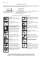
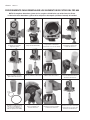
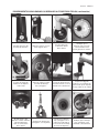
1
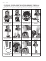
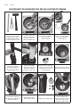
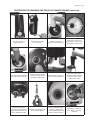
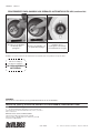
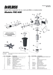
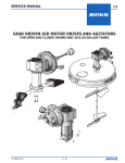
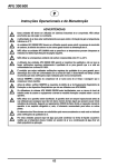
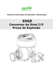
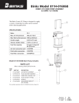
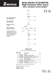
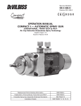
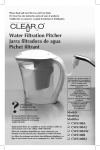
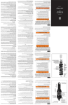
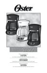
Service Bulletin SB-6-377 Replaces SB-6-132-D Filter, Regulator, Coalescer Air Preparation Unit Model FRC-650 ♦ ♦ ♦ ♦ ♦ Value your job and Protect your equipment: USE ORIGINAL DeVilbiss parts Replacement Kits Standard H K-4106 Replacement Kit of elements 21, 22 and 24 ♦ K-4107 Regulator Repair Kit (See ♦ items above) Fine Mesh K-4108 Filter Replacement Kit (1 micron / 0.1 micron) Item Part Number 1 K-4100 2 – 3 – 4 K-4101 5 – 6 FRC-018 7 – 8 – 9 K-4102 10 FRC-012 11 – 12 – 13 – 14 – 15 – Description Knob assembly Allen cap screw nº 10-24 UNC x 7/16” Regulator flange Regulator screw assembly Top spring Diaphragm assembly Shaft guide disk Nut Regulator seat assembly Gauge Allen cap screw 1/4”-20 UNC x 1/2” Nut 1/4” – 20 UNC Lid Nut 5/16” –18 UNC Allen cap screw 5/16”-18 UNC x 1.1/4” Item Part Number 16 17 18 K-4103 19 20 H21 H22 23 K-4104 H24 25 FRC-044 26 K-4105 27 FRC-043 28 FRC-046 29 - Description Bracket Body Ball valve assembly Swirl baffle Threaded rod Filtering element, 5 micron, standard Coalescent element, 1 micron, standard Nut base O-Ring / Seal Kit Automatic filter drain assembly Coalescent automatic drain assembly Coalescent reservoir Bowl gauge Bowl PAGE 2 SB-6-377 SAFETY PRECAUTIONS This manual contains information that is important for you to know and understand. This information relates to USER SAFETY and PREVENTING EQUIPMENT PROBLEMS. To help you recognize this information, we use the following symbols. Please pay particular attention to these sections. Note Important safety information – A hazard that may cause serious injury or loss of life. Important information that tells how to prevent damage to equipment, or how to avoid a situation that may cause minor inury. Information that you should pay special attention to. Read the following warnings before using this equipment. Read the Manual Before operating finishing equipment, read and understand all safety, operation and maintenance information provided in the operation manual. ELECTRIC SHOCK/GROUNDING Improper grounding or sparks can cause a hazardous condition and result in fire, explosion or electric shock and other serious injury. Wear Safety Glasses Failure to wear safety glasses with side shields could result in serious eye injury or blindness. PROJECTILE HAZARD You may be injured by venting liquids or gases that are released under pressure, or flying debris. De-energize, DEPRESSURIZE, Disconnect and Lock Out All Power Sources During Maintenance Failure to De-energize, disconnect and lock out all power supplies before performing equipment maintenance could cause serious injury or death. INSPECT THE EQUIPMENT DAILY Inspect the equipment for worn or broken parts on a daily basis. Do not operate the equipment if you are uncertain about its condition. Operator Training All personnel must be trained before operating finishing equipment. NEVER MODIFY THE EQUIPMENT Do not modify the equipment unless the manufacturer provides written approval. Equipment Misuse Hazard Equipment misuse can cause the equipment to rupture, malfunction, or start unexpectedly and result in serious injury. FIRE AND EXPLOSION HAZARD Improper equipment grounding, poor ventilation, open flame or sparks can cause hazardous conditions and result in fire or explosion and serious injury. Keep Equipment Guards in Place Do not operate the equipment if the safety devices have been removed. Know Where and How to Shut Off the Equipment in Case of an Emergency HIGH PRESSURE CONSIDERATION High pressure can cause serious injury. Relieve all pressure before servicing. Spray from the spray gun, hose leaks, or ruptured components can inject fluid into your body and cause extremely serious injury. STATIC CHARGE Fluid may develop a static charge that must be dissipated through proper grounding of the equipment, objects to be sprayed and all other electrically conductive objects in the dispensing area. Improper grounding or sparks can cause a hazardous condition and result in fire, explosion or electric shock and other serious injury. PRESSURE RELIEF PROCEDURE Always follow the pressure relief procedure in the equipment instruction manual. FOR FURTHER SAFETY INFORMATION REGARDING BINKS AND DEVILBISS EQUIPMENT, SEE THE GENERAL EQUIPMENT SAFETY BOOKLET (77-5300). SB-6-377 Page 3 The regulator is self relieving, and when it is necessary to lower the regulating outlet pressure, the relief device automatically relieves air pressure so that the air is regulated to the new set pressure indicated on the gauge (10). In addition to allowing for easy regulation to any pressure, the regulating knob is robust and solvent resistant. The gauge located on the bowl (28) indicates the air pressure available at the outlet identified as “line”. Installation The DeVilbiss FRC-650 should be installed in a vertical position at the downwards end of the line, using a coupling and a valve to shut the air flow at the time of maintenance. It should be installed close to the point of usage in a place of easy access to facilitate regulating, drainage and maintenance. Do not install the DeVilbiss FRC-650 in areas above equipment. Drained water may cause damage to the equipment. Regulating Operation After installing the DeVilbiss FRC-650, and before opening any of the ball valves, turn the regulating knob counter-clockwise so as to completely stop the flow of air. Note The DeVilbiss FRC-650 is a compact piece of equipment which brings together a pre-filter, coalescing filter and air regulator in a single unit. To ensure high level performance for many years, it is important to carefully follow the instructions in this manual. Specifications Model: FRC-650 Regulating type: Inlet thread: Valves Outlet threads: Regulated outlets: Air line outlet: Maximum temperature: Inlet maximum pressure: Regulated pressure: Filter element: Coalescent element: Body and Bowl: Draining fixture: Diaphragm 1/2"-14 Pipe Thread 1/4" NPS(M) 3 1 80°C 175 psi (12.3 kgf/cm²) 0-125 psi (0-8.8 kgf/cm²) 5 micron (standard)* 1 micron (standard)* Aluminum Automatic *1 micron filter element and 0.1 micron coalescent element are available in Replacement Kit K-4108. Purpose The purpose of the DeVilbiss FRC-650 is to remove humidity, oil and solid particles which exist in compressed air and provide clean, dry, regulated air. Important It should never be used under conditions that exceed the specified pressure and temperature. It should never be used in air systems destined for human breathing, nor in gas systems which are not inert. Operation Air enters the FRC-650 and is centrifuged by a deflector (19), which impels the liquid and solid particles to the walls of the bowl (29), where they trickle and accumulate at the bottom of the bowl, and will be periodically removed via the drain (25) located on the right. Then the air must travel through the pre-filter (21), which retains the remaining residues. Finally, the air goes to the coalescing element (22). The liquids condensed between the prefilter and the coalescing element trickle down and accumulate in the reservoir (27), and will be periodically removed via the drain (26) located on the left. The clean and dry air goes to the regulating valve that is controlled by the regulating knob (1). Open the desired ball valve, and turn the regulating knob clockwise until you reach the desired outlet pressure. When a new pressure is necessary, reach it from a pressure below the one required. Maintenance Disassembly of the regulator Before disassembly, close the air supply and turn the regulating knob (1), completely counter-clockwise so as to relieve the spring pressure (5). • Remove the screws (2) from the flange (3) and remove the knob assembly. • Remove the upper spring (5), the diaphragm assembly (6) and the shaft guide disk (7). • Use a 1” socket wrench to withdraw the nut (8) and have access to the sealing ring, the valve shaft and the lower spring (9). Disassembly of the filtering elements and valve Before you start disassembling, close the air supply and drain the filter to relieve the internal pressure of the bowl. • Remove screws (11) and manually remove the bowl (29). • Remove the nut base by turning it counter clockwise (23) and remove the elements (21) (22). • Take out the sealing rings. Cleaning and lubricating • Wash all parts. • After cleaning, carefully dry all parts. • Inspect the parts and replace the damaged ones with new DeVilbiss parts. Note • Lubricate o-rings and movable parts with a silicone free lubricant. • Before assembling the outfit, clean the body with a cloth and dry with compressed air. Attention DeVilbiss reserves the right to modify the characteristics of its products without previous warning. PAGE 4 SB-6-377 PROCEDURE FOR REPLACING THE FILTER ELEMENTS OF THE FRC-650 NOTE: When replacing seals and o-rings, be sure to lubricate them with a silicone-free lubricant. Lubrication of the seals and o-rings will improve their performance and aid in the assembly of the unit. Release the 4 screws in the bowl with a 3/16” wrench Remove the filter bowl Then remove the “L” cross section seal from the bowl Remove the o-ring from the external diameter of the nut base Remove the pre-filter by turning the nut base Remove the coalescent element Release the nut base Remove the o-ring ring from the internal diameter of the nut base Replace all the o-rings, seals, and filtering elements (Repair Kit K-4106) Lubricate the new o-ring and install in the nut base Fit the new pre-filter in the nut base Fit the new coalescent element in the center of the swirl baffle SB-6-377 Page 5 PROCEDURE FOR REPLACING THE FILTER ELEMENTS OF THE FRC-650 (continued) Now install the new pre-filter over the coalescent element And turn the filtering element nut base to fasten it Lubricate and install the new o-ring on the external diameter of the nut base Insert the bowl over the pre-filter Fit the bowl fitting into the proper position Screw the 4 screws in the body and tighten them with a 3/16” wrench Put the new “L” cross section seal in the bowl Value your job and Protect your equipment: USE ORIGINAL DeVilbiss parts DeVilbiss reserves the right to modify the characteristics of its products without previous warning. PAGE 6 SB-6-377 PROCEDURE FOR CHANGING THE FRC-650 AUTOMATIC DRAINS Required tools: 7/8” (22 mm) dia. wooden dowel, long nose pliers, a rubber mallet, and a ¾” wrench (not shown) Hold the “umbrella” type automatic drain restrainer with the pliers and pull it out. Remove the “umbrella” type automatic drain restrainer. Remove the “umbrella” type automatic drain with the pliers Place the bowl on the tool bench and place the wooden dowel on the outlet of the drain with the white ring. Hit the dowel with the rubber hammer until the coalescent reservoir comes out. Lift the bowl to get to the coalescent reservoir and the float of the second automatic drain. Inside the bowl you will see the float type drain body. Replace necessary parts. Place the float type drain in the smaller of the two holes in the base of the bowl. (Hole on the right as shown here.) Remove the retaining nut of the float type drain with a ¾” wrench. Remove the body of the float type drain. SB-6-377 Page 7 PROCEDURE FOR CHANGING THE FRC-650 AUTOMATIC DRAINS (continued) Screw on the float type drain nut. Tighten the nut with a ¾” wrench. Put the coalescent reservoir inside the bowl. Check if the reservoir is positioned correctly in the guide lines of the bowl. Place the wooden dowel in the coalescent reservoir. Turn the bowl over and center the outlet of the “umbrella” type drain. Put the bowl on a vise as shown in the illustration. Hit the wooden dowel with the rubber hammer until the reservoir fits tightly in the bowl The white ring of the reservoir should extend approximately 1/16” (1.5 mm) outside the bowl. Hold the “umbrella” type drain with the pliers. Fit the “umbrella” type drain into the O-ring located in the fitting in the bottom of the reservoir. Check if the “umbrella” type drain is correctly inserted. PAGE 8 SB-6-377 PROCEDURE FOR CHANGING THE FRC-650 AUTOMATIC DRAINS (continued) Put in the “umbrella” type drain restrainer. Check to see if the restrainer is correctly in place. Fit the restrainer in with the help of the dowel. DeVilbiss reserves the right to modify the characteristics of its products without previous warning. Value your job and Protect your equipment: USE ORIGINAL DeVilbiss parts WARRANTY This product is covered by DeVilbiss' 1 Year Limited Warranty. DeVilbiss Worldwide Sales and Service Listing: www.devilbiss.com Industrial Finishing DeVilbiss has authorized distributors throughout the world. For technical assistance or the distributor nearest you, see listing below. U.S./Canada Technical Service Office: 195 Internationale Blvd., Glendale Heights, IL 60139 Toll-Free Telephone: 1-888-992-4657 (U.S.A. and Canada only) Toll-Free Fax: 1-800-368-8401 5/08 ©2008 Inc. All rights reserved. Printed in U.S.A. Boletín de mantenimiento SB-6-377 Unidad de preparación de aire coalescente con filtro, regulador Modelo FRC-650 ♦ ♦ ♦ ♦ ♦ Valore su trabajo y Proteja sus equipos: USE PIEZAS ORIGINALES de DeVilbiss Kits de reemplazo Kit estándar H K-4106 de reemplazo de elemento 21, 22 y 24 Kit de reparación del ♦ K-4107 regulador (Ver ♦ artículos anteriores) Kit de reemplazo K-4108 del filtro de malla fina (1 micrón / 0.1 micrón) Art. 1 2 3 4 5 6 7 8 9 10 11 12 13 14 15 Núm. de pieza K-4100 – – K-4101 – FRC-018 – – K-4102 FRC-012 – – – – – Descripción Conjunto del botón Tornillo de casquete Allen nº 10-24 UNC x 7/16" Reborde del regulador Conjunto del tornillo del regulador Resorte superior Conjunto del diafragma Plato guía del eje Tuerca Conjunto del alojamiento del regulador Manómetro Tornillo de casquete Allen de 1/4"-20 UNC x 1/2" Tuerca de 1/4” – 20 UNC Tapa Tuerca de 5/16” –18 UNC Tornillo de casquete Allen de 5/16”-18 UNC x 1.1/4” Art. 16 17 18 19 20 H21 H22 23 H24 25 26 27 28 29 Núm. de pieza K-4103 K-4104 FRC-044 K-4105 FRC-043 FRC-046 - Descripción Soporte Cuerpo Conjunto de la válvula esférica Deflector de turbulencia Varilla roscada Elemento filtrador, 5 micrones, estándar Elemento coalescente, 1 micrón, estándar Base de la tuerca Kit de junta tórica/obturador Conjunto de filtro de drenaje automático Conjunto del drenaje automático coalescente Depósito coalescente Manómetro de la cubeta Cubeta PÁGINA 2 SB-6-377 PRECAUCIONES DE SEGURIDAD Este manual contiene información que es importante que usted conozca y comprenda. Esta información se relaciona con la SEGURIDAD DEL USUARIO y CÓMO EVITAR PROBLEMAS CON LOS EQUIPOS. Para ayudarle a reconocer esta información, utilizamos los siguientes símbolos. Por favor, preste atención especial a estas secciones. ADVERTENCIA PRECAUCIÓN Información importante de seguridad — Un riesgo que puede causar lesiones graves o la pérdida de vida. Información importante que le indica cómo prevenir daños al equipo o cómo evitar una situación que puede causar lesiones de poca gravedad. Nota Información a la que debe prestar atención especial. Lea las siguientes advertencias antes de usar este equipo. Lea el Manual Antes de operar los equipos de acabado, lea y comprenda toda la información de seguridad, operación y mantenimiento incluidaen el manual de operaciones. DESCARGA ELÉCTRICA/ PUESTA A TIERRA La puesta a tierra indebida o las chispas pueden ocasionar condiciones de peligro y producir incendios, explosiones o descargas eléctricas y otras lesiones graves. Use gafas protectoras No usar gafas protectoras con resguardos laterales puede ocasionar lesiones graves en los ojos o ceguera. PELIGRO DE PROYECTILES Usted puede resultar lesionado por dar salida a líquidos o gases liberados bajo presión o por restos volanderos. Desactive, DESPRESURICE, desconecte y bloquee todas las fuentes de energía durante el mantenimiento No desactivar, desconectar y bloquear todas las fuentes de suministro de energía antes de realizar operaciones de mantenimiento en los equipos puede ocasionar lesiones graves o la muerte. INSPECCIONE LOS EQUIPOS DIARIAMENTE Inspeccione diariamente los equipos para verificar que no tengan piezas gastadas o rotas. No opere los equipos si no está seguro de esta condición. Capacitación de los operadores Todos los miembros del personal deben ser capacitados antes de operar los equipos de acabado. NUNCA MODIFIQUE LOS EQUIPOS No modifique el equipo sin la autorización escrita del fabricante. Peligro de uso indebido del equipo El uso indebido del equipo puede ocasionar averías, mal funcionamiento o activación imprevista lo que a su vez puede producir lesiones graves. PELIGRO DE INCENDIO Y EXPLOSIÓN La puesta a tierra indebida de los equipos, la ventilación insuficiente, la llama abierta o las chispas pueden ocasionar condiciones de peligro y producir incendios, explosiones y otras lesiones graves. Mantenga las defensas del equipo en su lugar No operar los equipos si los dispositivos de seguridad fueron removidos. Sepa cómo y dónde desactivar los equipos en caso de emergencia. CONSIDERACIONES DE ALTA PRESIÓN La alta presión puede ocasionar lesiones graves. Antes de reparar o dar mantenimiento a los equipos, alivie toda la presión. El rociado de la pistola pulverizadora, los escapes de la manguera o componentes averiados pueden inyectar fluido en su organismo y ocasionar lesiones sumamente graves. CARGA ESTÁTICA Los fluidos pueden generar una carga estática que debe ser disipada mediante la debida puesta a tierra del equipo, los objetos que van a ser rociados y todos los demás objetos electroconductores en el área de suministro. La puesta a tierra indebida o las chispas pueden ocasionar condiciones de peligro y producir incendios, explosiones o descargas eléctricas y otras lesiones graves. PROCEDIMIENTO DE LIBERACIÓN DE PRESIÓN Siga siempre el procedimiento de liberación de presión que aparece en el manual de instrucciones del equipo. PARA MÁS INFORMACIÓN ACERCA DE LOS EQUIPOS BINKS Y DEVILBISS, CONSULTE EL FOLLETO DE SEGURIDAD GENERAL DE LOS EQUIPOS (77-5300). SB-6-377 PÁGINA 3 El regulador es auto-descargante, y cuando se hace necesario bajar la presión de salida reguladora, el descargador de presión reduce automáticamente la presión del aire de manera que el aire es regulado hasta la nueva presión fijada, indicada en el manómetro (10). Además de permitir la regulación fácil de cualquier presión, el botón regulador es sólido y resistente a los disolventes. El manómetro ubicado en la cubeta (28) indica la presión de aire disponible en la salida Identificada como “línea”. Instalación El modelo FRC-650 de DeVilbiss se debe instalar en posición vertical en el extremo descendente de la línea usando un acoplador y una válvula para cerrar el flujo de aire al momento del mantenimiento. Se debe instalar cerca del punto de uso en un lugar de fácil acceso para facilitar la regulación, el drenaje y el mantenimiento. No instale el modelo FRC-650 de DeVilbiss en áreas sobre el equipo. El agua drenada puede dañar el equipo. Operación de regulación Después de instalar el modelo FRC-650 de DeVilbiss y antes de abrir cualquiera de las válvulas esféricas, gire el botón regulador en sentido antihorario para detener completamente el flujo de aire. Nota El modelo FRC-650 de DeVilbiss es una pieza compacta de equipo compuesto por un prefiltro, un filtro coalescente y un regulador de aire en una sola unidad. Para asegurar un alto nivel de rendimiento por muchos años, es importante seguir cuidadosamente las Instrucciones contenidas en este manual. Abra la válvula esférica que desea abrir, y gire el botón regulador en sentido horario hasta alcanzar la presión de salida deseada. Especificaciones Mantenimiento Modelo: FRC-650 Tipo de regulación: Rosca de entrada: Roscas de entrada de las válvulas: Salidas reguladas: Salida de la línea de aire: Temperatura máxima: Presión de admisión máxima: Presión regulada: Filtro: Filtro coalescente: Cuerpo y cubeta: Elemento de drenaje: Diafragma Rosca de tubo de 1/2"-14 1/4" NPS(M) 3 1 80°C 175 psi (12.3 kgf/cm²) 0-125 psi (0-8.8 kgf/cm²) de 5 micrones (estándar)* de 1 micrón (estándar)* Aluminio Automático *El filtro de 1 micrón y el elemento coalescente de 0.1 micrón están disponibles en el Kit de reemplazo K-4108. Cuando se necesita una nueva presión, alcáncela desde una presión inferior a la necesaria. Desmontaje del regulador ADVERTENCIA Antes de desmontar, cierre el suministro de aire y gire completamente el botón regulador (1), en sentido antihorario para reducir la presión del resorte (5). • Quite los tornillos (2) del reborde (3) y quite el conjunto del botón. • Quite el resorte superior (5), el conjunto del diafragma (6) y el plato guía del eje (7). • Utilice una llave de casquillo de 1" para retirar la tuerca (8) y tener acceso al anillo obturador, el eje de la válvula y el resorte inferior (9). Desmontaje de los elementos filtradores y la válvula ADVERTENCIA Función La función del modelo FRC-650 de DeVilbiss es eliminar la humedad, el aceite y las partículas sólidas que existen en el aire comprimido y proporcionar aire regulado seco y limpio. ADVERTENCIA Importante Nunca se debe utilizar bajo condiciones que sobrepasen la presión y la temperatura especificadas. Nunca se debe utilizar en sistemas de aire destinados a la aspiración humana ni en sistemas de gas que no sean inertes. Operación El aire penetra en el FRC-650 y es centrifugado por un deflector (19), que impulsa las partículas líquidas y sólidas hacia las paredes de la cubeta (29), donde se escurren y se acumulan en el fondo de la cubeta, y serán eliminadas periódicamente a través del drenaje (25) ubicado a la derecha. Luego el aire debe pasar a través del prefiltro (21), que retiene los residuos restantes. Por último, el aire pasa al elemento coalescente (22). Los líquidos condensados entre el prefiltro y el elemento coalescente se escurren y se acumulan en el depósito (27), y serán eliminados periódicamente por el drenaje (26) ubicado a la izquierda. El aire limpio y seco pasa a la válvula reguladora que es controlada por el botón regulador (1). Antes de comenzar a desmontar, cierre el suministro de aire y drene el filtro para descargar la presión Interna de la cubeta. • Quite los tornillos (11) y saque la cubeta con las manos (29). • Quite la base de la tuerca haciéndola girar en sentido horario (23) y quite los elementos (21) (22). • Saque los anillos obturadores. Limpieza y lubricación • Lave todas las piezas. • Después de limpiar, seque todas las partes cuidadosamente. • Inspeccione las piezas y reemplace las que estén dañadas con piezas nuevas de DeVilbiss. Nota • Lubrique las juntas tóricas y las piezas movibles con un lubricante sin silicona. • Antes de ensamblar el equipo, limpie el cuerpo con un paño y séquelo con aire comprimido. Atención DeVilbiss se reserva el derecho de modificar las características de sus productos sin previo aviso. PÁGINA 4 SB-6-377 PROCEDIMIENTO PARA REEMPLAZAR LOS ELEMENTOS DE FILTRO DEL FRC-650 NOTA: Al reemplazar obturadores y juntas tóricas, asegúrese de lubricarlos con un lubricante sin silicona. La lubricación de los obturadores y juntas tóricas mejorará su desempeño y facilitará el montaje de la unidad. Suelte los 4 tornillos en la cubeta con una llave inglesa de 3/16” Saque la cubeta del filtro Luego quite el obturador transversal en “L” de la cubeta Quite el anillo de la junta tórica del diámetro externo de la base de la tuerca Quite el prefiltro haciendo girar la base de la tuerca Quite el elemento coalescente Quite la base de la tuerca Quite el anillo de la junta tórica del diámetro interno de la base de la tuerca Lubrique la nueva junta tórica e instálela en la base de la tuerca Introduzca el nuevo prefiltro en la base de la tuerca Introduzca el nuevo elemento coalescente en el centro del deflector de turbulencia Reemplace todas las juntas tóricas, los obturadores y los elementos filtradores (Kit de reparación K-4106) SB-6-377 PÁGINA 5 PROCEDIMIENTO PARA REEMPLAZAR LOS ELEMENTOS DE FILTRO DEL FRC-650 (continuación) Ahora instale el nuevo prefiltro sobre el elemento coalescente Y gire la base de la tuerca del elemento filtrador para ajustarlo Lubrique e instale la nueva junta tórica en el diámetro externo de la base de la tuerca Inserte la cubeta en el prefiltro Ponga el accesorio de montaje de la cubeta en la posición adecuada Atornille los 4 tornillos en el cuerpo y apriételos con una llave inglesa de 3/16” Ponga el nuevo obturador transversal en “L” en la cubeta Valore su trabajo y Proteja sus equipos: USE PIEZAS ORIGINALES de DeVilbiss DeVilbiss se reserva el derecho de modificar las características de sus productos sin previo aviso. PÁGINA 6 SB-6-377 PROCEDIMIENTO PARA CAMBIAR LOS DRENAJES AUTOMÁTICOS FRC-650 Herramientas necesarias: espiga de madera de 7/8” (22 mm) de diá., pinzas de puntas largas, un martillo de goma y una llave inglesa de ¾” (no ilustrada) Sostenga el restringidor de drenaje automático tipo "paraguas" con las pinzas y hálelo para sacarlo. Quite el restringidor de drenaje automático tipo "paraguas". Quite el drenaje automático tipo "paraguas" con las pinzas Coloque la cubeta en el banco de herramientas y coloque la espiga de madera en la salida del drenaje con el anillo blanco. Golpee la espiga con el martillo de goma hasta que salga el depósito coalescente. Levante la cubeta para alcanzar el depósito coalescente y el flotador del segundo drenaje automático. Dentro de la cubeta usted verá el drenaje tipo flotador. Reemplace las piezas necesarias. Coloque el drenaje tipo flotador en el más pequeño de los dos orificios en la base de la cubeta. (Orificio a la derecha como se ilustra aquí). Quite la tuerca de retención del drenaje tipo flotador con una llave inglesa de ¾”. Quite el cuerpo del drenaje tipo flotador. SB-6-377 PÁGINA 7 PROCEDIMIENTO PARA CAMBIAR LOS DRENAJES AUTOMÁTICOS FRC-650 (continuación) Atornille la tuerca del drenaje tipo flotador. Apriete la tuerca con una llave inglesa de ¾”. Ponga el depósito coalescente dentro de la cubeta. Verifique que el depósito esté colocado correctamente en las líneas guías de la cubeta. Coloque la espiga de madera en el depósito coalescente. Voltee la cubeta y centre la salida del drenaje tipo "paraguas". Ponga la cubeta en una prensa de tornillo como se muestra en la ilustración. Golpee la espiga de madera con el martillo de goma hasta que el depósito encaje ceñido en la cubeta Sostenga el drenaje tipo “paraguas” con las pinzas. Introduzca el drenaje tipo “paraguas” en la junta tórica ubicada en el accesorio de montaje al fondo del depósito. Verifique que el drenaje tipo “paraguas” esté insertado correctamente. El anillo blanco del depósito se debe extender aproximadamente 1/16” (1.5 mm) fuera de la cubeta. PÁGINA 8 SB-6-377 PROCEDIMIENTO PARA CAMBIAR LOS DRENAJES AUTOMÁTICOS FRC-650 (continuación) Introduzca el restringidor del drenaje tipo “paraguas”. Inserte el restringidor con la ayuda de la espiga. Verifique que el restringidor se encuentre correctamente en su lugar. DeVilbiss se reserva el derecho de modificar las características de sus productos sin previo aviso. Valore su trabajo y Proteja sus equipos: USE PIEZAS ORIGINALES de DeVilbiss GARANTÍA Este producto está cubierto por la garantía limitada de un año de DeVilbiss. Centros de venta y servicios de DeVilbiss a escala mundial: www.devilbiss.com Industrial Finishing DeVilbiss tiene distribuidores autorizados en todo el mundo. Para asistencia técnica o localizar al distribuidor más cercano, consulte la lista a continuación. Oficina de servicios técnicos en EE.UU./Canadá: 195 Internationale Blvd., Glendale Heights, IL 60139 Teléfono gratuito: 1-888-992-4657 (sólo en EE.UUU. y Canadá) Fax gratuito: 1-800-368-8401 5/08 ©2008 Inc. Todos los derechos reservados. Impreso en EE.UU.