1
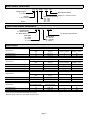
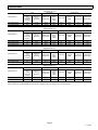
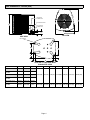
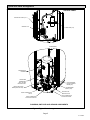
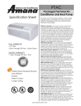
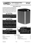
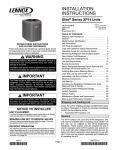
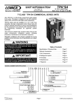
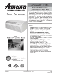
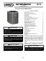
XC16
Corp. 0625−L5
Revised October 8, 2010
Service Literature
XC16 (HFC−410A) SERIES UNITS
WARNING
Improper installation, adjustment, alteration, service or
maintenance can cause personal injury, loss of life, or
damage to property.
Installation and service must be performed by a licensed
professional installer (or equivalent) or a service agency.
CAUTION
Physical contact with metal edges and corners while
applying excessive force or rapid motion can result in
personal injury. Be aware of, and use caution when
working near these areas during installation or while
servicing this equipment.
IMPORTANT
TABLE OF CONTENTS
Unit Dimensions . . . . . . . . . . . . . . . . . . . . . . . . . . . . . . .
4
Model Number Identification . . . . . . . . . . . . . . . . . . . .
2
Typical Serial Number Identification . . . . . . . . . . . . . .
2
Specifications . . . . . . . . . . . . . . . . . . . . . . . . . . . . . . . . .
2
Electrical Data . . . . . . . . . . . . . . . . . . . . . . . . . . . . . . . .
3
Unit Parts Arrangement . . . . . . . . . . . . . . . . . . . . . . . .
5
Operating Gauge Set and Service Valves . . . . . . . . .
6
Recovering Refrigerant from System . . . . . . . . . . . . .
8
Unit Placement . . . . . . . . . . . . . . . . . . . . . . . . . . . . . . . .
9
Removing and Installing Panels . . . . . . . . . . . . . . . . . 11
New or Replacement Line Set . . . . . . . . . . . . . . . . . . . 13
Brazing Connections . . . . . . . . . . . . . . . . . . . . . . . . . . . 15
Flushing Line Set and Indoor Coil . . . . . . . . . . . . . . . . 18
Installing Indoor Metering Device . . . . . . . . . . . . . . . . 19
Leak Test Line Set and Indoor Coil . . . . . . . . . . . . . . . 20
Evacuating Line Set and Indoor Coil . . . . . . . . . . . . . 21
Electrical . . . . . . . . . . . . . . . . . . . . . . . . . . . . . . . . . . . . . 22
Servicing Units Void of Charge . . . . . . . . . . . . . . . . . . 23
Unit Start−Up . . . . . . . . . . . . . . . . . . . . . . . . . . . . . . . . . . 23
System Refrigerant . . . . . . . . . . . . . . . . . . . . . . . . . . . . 23
System Operation . . . . . . . . . . . . . . . . . . . . . . . . . . . . . 28
Maintenance . . . . . . . . . . . . . . . . . . . . . . . . . . . . . . . . . . 28
Checklist . . . . . . . . . . . . . . . . . . . . . . . . . . . . . . . . . . . . . 31
Unit Wiring Diagram and Sequence of
Operations . . . . . . . . . . . . . . . . . . . . . . . . . . . . . . . . . . . . 32
The XC16 Air Conditioners, which will also be referred to in
this instruction as the outdoor unit, uses HFC−410A
refrigerant. This outdoor unit must be installed with a
matching indoor unit and line set as outlined in the Lennox
XC16 Engineering Handbook. XC16 Air Conditioners are
designed for use in thermal expansion valve (TXV)
systems.
NOTE The XC16 outdoor unit is rated for 230V
applications only. A hard-start kit is required for
applications where the supply voltage is less than 230V.
IMPORTANT
The Clean Air Act of 1990 bans the intentional venting of
refrigerant (CFCs, HCFCs and HFCs) as of July 1, 1992.
Approved methods of recovery, recycling or reclaiming
must be followed. Fines and/or incarceration may be
levied for noncompliance.
This unit must be matched with an indoor coil as specified in Lennox XC16 Engineering Handbook. Coils previously charged with HCFC−22 must be flushed.
Page 1
Model Number Identification
X C 16 XXX
230
03
Refrigerant Type
X = R−410A
Minor Revision Number
Voltage 230 = 208/230V−1ph−60hz
Unit Type
C = Air Conditioner
Nominal Cooling Capacity
024 = 2 tons
036 = 3 tons
048 = 4 tons
060 = 5 tons
Series
Typical Serial Number Identification
19 09
C
Location Code
19 = Saltillo, Mexico
58 = Marshalltown, IA
05716
5 (or 6) Digit Unique Number
Year Code
08 = 2008
09 = 2009
10 = 2010
Month Code
A = January
B = February
C = March
Specifications
Unit
Model Number
Outdoor Fan
Sound Rating Number
(dB)1
Factory Refrigerant
Charge2
Number of Blades
Diameter − inches.
XC16−024−230−01
74
7 lbs. 5 oz.
3
18
XC16−024−230−02
74
7 lbs. 6 oz.
4
22
Unit
Model Number
Outdoor Fan
Sound Rating Number
(dB)1
Factory Refrigerant
Charge2
Number of Blades
Diameter − inches.
XC16−036−230−01
76
8 lbs. 9 oz.
4
22
XC16−036−230−02
76
8 lbs. 9 oz.
4
22
XC16−036−230−03
76
8 lbs. 8 oz.
4
22
Unit
Model Number
Outdoor Fan
Sound Rating Number
(dB)1
Factory Refrigerant
Charge2
Number of Blades
Diameter − inches.
XC16−048−230−01
76
11 lbs. 4 oz.
4
22
XC16−048−230−02
76
11 lbs. 4 oz.
4
22
Unit
Model Number
Outdoor Fan
Sound Rating Number
(dB)1
Factory Refrigerant
Charge2
Number of Blades
Diameter − inches.
XC16−060−230−01
78
14 lbs. 2 oz.
3
26
XC16−060−230−02
78
14 lbs. 2 oz.
3
26
1 Tested
according to AHRI Standard 270−2008 test conditions.
2 Refrigerant
charge sufficient for 15 feet length of refrigerant lines.
Page 2
Electrical Data
208/230V−60 Hz−1 Ph
Unit
Compressor
Condenser Fan
Maximum
Over−
current
Protection
(amps)1
Minimum
Circuity
Ampacity2
Rated Load
Amps (RLA)
Locked
Rotor
Amps
(LRA)
Motor HP
Nominal
RPM
Full Load
Amps (FLA)
XC16−024−230−01
20
13.6
10.25
52.0
1/10
1075
0.7
1.4
XC16−024−230−02
20
13.6
10.25
52.0
1/6
825
1.1
1.87
Model Number
Locked Rotor
Amps (LRA)
208/230V−60 Hz−1 Ph
Unit
Compressor
Condenser Fan
Maximum
Over−
current
Protection
(amps)1
Minimum
Circuity
Ampacity2
Rated Load
Amps (RLA)
Locked
Rotor
Amps
(LRA)
Motor HP
Nominal
RPM
Full Load
Amps (FLA)
XC16−036−230−01
35
22.0
16.67
82.0
1/6
825
1.1
2.1
XC16−036−230−02
35
22.0
16.67
82.0
1/6
825
1.1
1.87
XC16−036−230−03
35
22.0
16.67
82.0
1/10
825
1.1
1.87
Model Number
Locked Rotor
Amps (LRA)
208/230V−60 Hz−1 Ph
Unit
Compressor
Condenser Fan
Maximum
Over−
current
Protection
(amps)1
Minimum
Circuity
Ampacity2
Rated Load
Amps (RLA)
Locked
Rotor
Amps
(LRA)
Motor HP
Nominal
RPM
Full Load
Amps (FLA)
Locked Rotor
Amps (LRA)
XC16−048−230−01
45
28.2
21.15
96.0
1/4
825
1.7
3.1
XC16−048−230−02
45
28.2
21.15
96.0
1/4
825
1.7
3.1
Model Number
208/230V−60 Hz−1 Ph
Unit
Compressor
Condenser Fan
Maximum
Over−
current
Protection
(amps)1
Minimum
Circuity
Ampacity2
Rated Load
Amps (RLA)
Locked
Rotor
Amps
(LRA)
Motor HP
Nominal
RPM
Full Load
Amps (FLA)
Locked Rotor
Amps (LRA)
XC16−060−230−01
55
33.9
25.64
118.0
1/3
825
1.8
2.9
XC16−060−230−02
55
33.9
25.87
118.0
1/3
825
1.8
2.9
Model Number
1 HACR
2 Refer
type circuit breaker or fuse.
to National or Canadian Electrical Code manual to determine wire, fuse and disconnect size requirements.
Page 3
XC16 SERIES
Unit Dimensions − Inches (mm)
LIQUID LINE
CONNECTION
C
ELECTRICAL INLETS
A
SUCTION LINE
CONNECTION
4−3/4"
(121)
4−1/2"
(108)
B
TOP VIEW
SIDE VIEW
UNIT SUPPORT
FEET
D
K
E
J
H
G
F
XC14−024 TO −060 BASE WITH
ELONGATED LEGS
A
B
C
XC16−024−230−01
35 (889)
27 (686)
28 (711)
XC16−024−230−02
and later
39 (991)
30−1/2 (775)
35 (889)
XC16−036−230−01
31 (787)
30−1/2 (775)
35 (889)
XC16−036−230−03
and later
45 (1143)
30−1/2 (775)
35 (889)
XC16−048−230−01
39 (991)
30−1/2 (775)
35 (889)
XC16−060−230−01
and later
39 (991)
35−1/2 (902)
39−3/8
(1001)
Model Number
D
E
F
G
H
J
K
13−7/8 (352) 7−3/4 (197)
3−1/4 (83)
27−1/8 (689)
3−5/8 (92)
4−1/2 (114)
20−5/8 (524)
16−7/8 (429) 8−3/4 (222)
3−1/8 (79)
30−3/4 (781) 4−5/8 (117)
3−3/4 (95)
26−7/8 (683)
Page 4
Typical Unit Parts Arrangement
CONTROL PANEL
CONTACTOR−1POLE (K1−1)
GROUND LUG
CAPACITOR (C12)
COMPRESSOR
COMPRESSOR
HARNESS
CRANKCASE
THERMOSTAT
(S40) −048 AND
−060 UNITS ONLY
HIGH PRESSURE
SWITCH (MANUAL
RESET) (S4)
LIQUID LINE FILTER
DRIER (SINGLE FLOW)
LOW PRESSURE
SWITCH (S87)
SUCTION LINE
SERVICE VALVE
LIQUID LINE SERVICE
VALVE
FIELD CONNECTION
FOR SUCTION LINE
FIELD CONNECTION
FOR LIQUID LINE SET
PLUMBING, SWITCHES AND SENSOR COMPONENTS
Figure 1. Typical Parts Arrangements
Page 5
XC16 SERIES
IMPORTANT
WARNING
Only use Allen wrenches of sufficient hardness (50Rc −
Rockwell Harness Scale minimum). Fully insert the
wrench into the valve stem recess.
Service valve stems are factory−torqued (from 9 ft−lbs for
small valves, to 25 ft−lbs for large valves) to prevent
refrigerant loss during shipping and handling. Using an
Allen wrench rated at less than 50Rc risks rounding or
breaking off the wrench, or stripping the valve stem
recess.
See the Lennox Service and Application Notes #C−08−1
for further details and information.
This product and/or the indoor unit it is matched with may
contain fiberglass wool.
Disturbing
the
insulation
during
installation,
maintenance, or repair will expose you to fiberglass wool
dust. Breathing this may cause lung cancer. (Fiberglass
wool is known to the State of California to cause cancer.)
Fiberglass wool may also cause respiratory, skin, and
eye irritation.
To reduce exposure to this substance or for further
information, consult material safety data sheets
available from address shown below, or contact your
supervisor.
IMPORTANT
Lennox Industries Inc.
P.O. Box 799900
Dallas, TX 75379−9900
To prevent stripping of the various caps used, the
appropriately sized wrench should be used and fitted
snugly over the cap before tightening.
Table 1. Torque Requirements
WARNING
Electric Shock Hazard. Can cause injury
or death. Unit must be grounded in
accordance with national and local
codes.
Line voltage is present at all components
when unit is not in operation on units with
single-pole contactors. Disconnect all
remote electric power supplies before
opening access panel. Unit may have
multiple power supplies.
Parts
Recommended Torque
Service valve cap
8 ft.− lb.
11 NM
Sheet metal screws
16 in.− lb.
2 NM
Machine screws #10
28 in.− lb.
3 NM
Compressor bolts
90 in.− lb.
10 NM
Gauge port seal cap
8 ft.− lb.
11 NM
USING MANIFOLD GAUGE SET
When checking the system charge, only use a manifold
gauge set that features low loss anti−blow back fittings.
Operating Gauge Set and Service Valves
These instructions are intended as a general guide and do
not supersede local codes in any way. Consult authorities
who have jurisdiction before installation.
TORQUE REQUIREMENTS
When servicing or repairing heating, ventilating, and air
conditioning components, ensure the fasteners are
appropriately tightened. Table 1 lists torque values for
fasteners.
Manifold gauge set used with HFC−410A refrigerant
systems must be capable of handling the higher system
operating pressures. The gauges should be rated for use
with pressures of 0 − 800 psig on the high side and a low
side of 30" vacuum to 250 psig with dampened speed to
500 psi. Gauge hoses must be rated for use at up to 800
psig of pressure with a 4000 psig burst rating.
OPERATING SERVICE VALVES
The liquid and vapor line service valves are used for
removing refrigerant, flushing, leak testing, evacuating,
checking charge and charging.
Each valve is equipped with a service port which has a
factory−installed valve stem. Figure 2 provides information
on how to access and operating both angle and ball service
valves.
Page 6
SERVICE VALVES ANGLE AND BALL
Operating Angle Type Service Valve:
1. Remove stem cap with an appropriately sized wrench.
2. Use a service wrench with a hex−head extension (3/16" for liquid line valve sizes and 5/16" for vapor line valve sizes) to back
the stem out counterclockwise as far as it will go.
SERVICE PORT CAP
SERVICE PORT CORE
TO INDOOR
UNIT
(VALVE STEM SHOWN
CLOSED) INSERT HEX
WRENCH HERE
(VALVE STEM SHOWN OPEN)
INSERT HEX WRENCH HERE
SERVICE PORT
CORE
STEM CAP
TO OUTDOOR UNIT
ANGLE−TYPE SERVICE VALVE
(FRONT−SEATED CLOSED)
ANGLE−TYPE SERVICE VALVE
(BACK−SEATED OPENED)
When service valve is OPEN, the service port is
open to linE set, indoor and outdoor unit.
To Access Service Port:
Operating Ball Type Service Valve:
A service port cap protects the service port core from contamination and
serves as the primary leak seal.
1. Remove stem cap with an appropriately sized wrench.
2. Use an appropriately sized wrenched to open. To open valve,
roate stem counterclockwise 90°. To close rotate stem clockwise
90°.
TO INDOOR UNIT
TO OPEN ROTATE STEM
COUNTERCLOCKWISE 90°.
TO CLOSE ROTATE STEM
CLOCKWISE 90°.
1. Remove service port cap with an appropriately sized wrench.
2. Connect gauge set to service port.
3. When testing is completed, replace service port cap and tighten as
follows:
BALL (SHOWN
CLOSED)
VALVE
STEM
With torque wrench: Finger tighten and
torque cap per table 1.
Without torque wrench: Finger tighten and
use an appropriately sized wrench to turn
an additional 1/6 turn clockwise.
Reinstall Stem Cap:
1/6 TURN
11 12
10
9
8
7 6
1
5
2
3
4
Stem cap protects the valve stem from damage and serves as the
primary seal. Replace the stem cap and tighten as follows:
SERVICE PORT
1/12 TURN
SERVICE PORT
CORE
SERVICE PORT
CAP
TO OUTDOOR
UNIT
WHEN SERVICE VALVE IS CLOSED, THE SERVICE PORT IS OPEN
TO THE LINE SET AND INDOOR UNIT.
STEM CAP
With Torque Wrench: Finger tighten and
then torque cap per table 1.
Without Torque Wrench: Finger tighten and use an appropriately sized
wrench to turn an additional 1/12 turn
clockwise.
11 12 1
2
10
9
3
4
8
7 6 5
NOTE A label with specific torque requirements may be affixed to the stem cap. If the label is present, use the specified torque.
Figure 2. Angle and Ball Service Valves
Page 7
XC16 SERIES
Recovering Refrigerant from System
1
2
CONNECT MANIFOLD GAUGE SET
DISCONNECT POWER
Disconnect all power to the existing outdoor unit at the disconnect
switch or main fuse box/breaker panel.
Connect a gauge set, clean recovery cylinder and a recovery
machine to the service ports of the existing unit. Use the
instructions provided with the recovery machine to make the
connections.
MAIN FUSE BOX/BREAKER PANEL
MAIN FUSE
BOX/BREAKER
PANEL
MANIFOLD GAUGES
RECOVERY MACHINE
DISCONNECT
SWITCH
LOW
CLEAN RECOVERY
CYLINDER
3
RECOVERING REFRIGERANT
HIGH
OUTDOOR UNIT
Remove existing HCFC−22 refrigerant using one of the following procedures:
IMPORTANT Some system configurations may contain higher than normal refrigerant charge due to either large internal coil volumes,
and/or long line sets.
METHOD 1:
Us this method if the existing outdoor unit is not equipped with shut−off valves, or if the unit is not operational and you plan to use the existing
HCFC−22 to flush the system.
Remove all HCFC−22 refrigerant from the existing system. Check gauges after shutdown to confirm that the entire system is completely void of
refrigerant.
METHOD 2:
Use this method if the existing outdoor unit is equipped with manual shut−off valves, and you plan to use new HCFC−22 refrigerant to flush the
system.
The following devices could prevent full system charge recovery into the outdoor unit:
Outdoor unit’s high or low−pressure switches (if applicable) when tripped can cycle the compressor OFF.
Compressor can stop pumping due to tripped internal pressure relief valve.
Compressor has internal vacuum protection that is designed to unload the scrolls (compressor stops pumping) when the pressure ratio meets
a certain value or when the suction pressure is as high as 20 psig. (Compressor suction pressures should never be allowed to go into a vacuum.
Prolonged operation at low suction pressures will result in overheating of the scrolls and permanent damage to the scroll tips, drive bearings and
internal seals.)
Once the compressor can not pump down to a lower pressure due to one of the above system conditions, shut off the vapor valve. Turn OFF the
main power to unit and use a recovery machine to recover any refrigerant left in the indoor coil and line set.
Perform the following task:
A
Start the existing HCFC−22 system in the cooling mode and close the liquid line valve.
B
Use the compressor to pump as much of the existing HCFC−22 refrigerant into the outdoor unit until the outdoor system is full. Turn the outdoor unit
main power OFF and use a recovery machine to remove the remaining refrigerant from the system.
NOTE It may be necessary to bypass the low pressure switches (if equipped) to ensure complete refrigerant evacuation.
C
D
When the low side system pressures reach 0 psig, close the vapor line valve.
Check gauges after shutdown to confirm that the valves are not allowing refrigerant to flow back into the low side of the system.
Figure 3. Refrigerant Recovery
Page 8
CLEARANCE ON ALL SIDES INCHES (MILLIMETERS)
6 (152)
ACCESS PANEL
CONTROL PANEL
ACCESS
LOCATION
30 (762)
12 (305)
NOTES:
Clearance to one of the other three
sides must be 36 inches (914mm).
Clearance to one of the remaining
two sides may be 12 inches
(305mm) and the final side may be
6 inches (152mm).
LINE SET
CONNECTIONS
36 (914)
MINIMUM CLEARANCE
ABOVE UNIT
48 (1219)
MINIMUM CLEARANCE BETWEEN
TWO UNITS
24 (610)
Figure 4. Installation Clearances
In order to avoid injury, take proper precaution when
lifting heavy objects.
PLACING UNIT ON SLAB
When installing unit at grade level, the top of the slab
should be high enough above grade so that water from
higher ground will not collect around the unit. The slab
should have a slope tolerance as described in figure 5,
detail B.
NOTE If necessary for stability, anchor unit to slab as
described in figure 5, detail D.
See Unit Dimensions on page 3 for sizing mounting slab,
platforms or supports. Refer to figure 4 for mandatory
installation clearance requirements.
ELEVATING THE UNIT
Units are outfitted with elongated support feet as illustrated
in figure 5, detail C.
POSITIONING CONSIDERATIONS
Consider the following when positioning the unit:
If additional elevation is necessary, raise the unit by
extending the height of the unit support feet. This may be
achieved by using a 2 inch (50.8mm) Schedule 40 female
threaded adapter.
The specified coupling will fit snuggly into the recessed
portion of the feet. Use additional 2 inch (50.8mm)
Schedule 40 male threaded adaptors which can be
threaded into the female threaded adaptors to make
additional adjustments to the level of the unit.
NOTE Keep the height of extenders short enough to
ensure a sturdy installation. If it is necessary to extend
further, consider a different type of field−fabricated
framework that is sturdy enough for greater heights.
Unit Placement
CAUTION
Some localities are adopting sound ordinances based
on the unit’s sound level registered from the adjacent
property, not from the installation property. Install the
unit as far as possible from the property line.
When possible, do not install the unit directly outside
a window. Glass has a very high level of sound
transmission. For proper placement of unit in relation
to a window see the provided illustration in figure 5,
detail A.
Page 9
XC16 SERIES
DETAIL A Outside Unit Placement
Install unit away from windows.
DETAIL B Slab Mounting at Ground Level
Install unit level or, if on a slope, maintain slope tolerance of two (2)
degrees (or two inches per five feet [50 mm per 1.5 m]) away from
building structure.
BUILDING
STRUCTURE
MOUNTING
SLAB
TWO 90° ELBOWS INSTALLED IN LINE SET WILL
REDUCE LINE SET VIBRATION.
DETAIL C Elevated Slab Mounting
using Feet Extenders
GROUND LEVEL
STABILIZING UNIT ON UNEVEN SURFACES
DETAIL D Slab Side Mounting
#10 1/2" LONG SELF−DRILLING
SHEET METAL SCREWS
COIL
STABILIZING BRACKET (18 GAUGE
METAL 2" WIDTH; HEIGHT AS
REQUIRED)
BASE PAN
#10 1−1/4" LONG HEX HD SCREW
AND FLAT WASHER
CORNER POST
BASE
Concrete slab use two plastic anchors (hole
drill 1/4")
Wood or plastic slab no plastic anchor (hole
drill 1/8")
DETAIL E Deck Top Mounting
Stabilizing bracket (18 gauge metal 2" (50.8mm) width; height as required); bend to form
right angle as exampled below.
LEG DETAIL
MINIMUM ONE
PER SIDE
2" (50.8MM) SCH 40
FEMALE THREADED
ADAPTER
2" (50.8MM) SCH 40
MALE THREADED
ADAPTER
SAME FASTENERS AS
SLAB SIDE MOUNTING.
Use additional 2" SCH 40 male threaded adapters
which can be threaded into the female threaded
adapters to make additional adjustments to the level of
the unit.
FOR EXTRA
STABILITY
One bracket per side (minimum). For extra stability, two brackets per side, two inches
(51mm) from each corner.
IMPORTANT To help stabilize an outdoor unit, some installations may require strapping the unit to the pad using brackets and anchors
commonly available in the marketplace.
Figure 5. Placement, Slab Mounting and Stabilizing Unit
Page 10
STABILIZING UNIT ON UNEVEN SURFACES
NOTICE
IMPORTANT
Unit Stabilizer Bracket Use (field−provided):
Always use stabilizers when unit is raised above the
factory height. (Elevated units could become unstable in
gusty wind conditions).
Stabilizers may be used on factory height units when
mounted on unstable an uneven surface.
With unit positioned at installation site, perform the
following:
Roof Damage!
This system contains both refrigerant and oil. Some
rubber roofing material may absorb oil and cause the
rubber to swell when it comes into contact with oil. The
rubber will then bubble and could cause leaks. Protect
the roof surface to avoid exposure to refrigerant and oil
during service and installation. Failure to follow this
notice could result in damage to roof surface.
Removing and Installing Panels
IMPORTANT
1. Remove two side louvered panels to expose the unit
base.
Do not allow panels to hang on unit by top tab. Tab is for
alignment and not designed to support weight of panel.
2. Install the brackets as illustrated in figure 5, detail D or
E using conventional practices.
IMPORTANT
To help stabilize an outdoor unit, some installations may
require strapping the unit to the pad using brackets and
anchors commonly available in the marketplace.
3. Replace the panels after installation is complete.
ROOF MOUNTING
Install the unit a minimum of 6 inches (152 mm) above the
roof surface to avoid ice build−up around the unit. Locate
the unit above a load bearing wall or area of the roof that
can adequately support the unit. Consult local codes for
rooftop applications.
If unit coil cannot be mounted away from prevailing winter
winds, a wind barrier should be constructed. Size barrier at
least the same height and width as outdoor unit. Mount
barrier 24 inches (610 mm) from the sides of the unit in the
direction of prevailing winds.
WARNING
To prevent personal injury, or damage to panels, unit or
structure, be sure to observe the following:
While installing or servicing this unit, carefully stow all
removed panels out of the way, so that the panels will not
cause injury to personnel, nor cause damage to objects
or structures nearby, nor will the panels be subjected to
damage (e.g., being bent or scratched).
While handling or stowing the panels, consider any
weather conditions, especially windy conditions, that
may cause panels to be blown around and battered.
Page 11
XC16 SERIES
LOUVERED PANEL REMOVAL
Remove the louvered panels as follows:
1. Remove two screws, allowing the panel to swing open slightly.
2. Hold the panel firmly throughout this procedure. Rotate bottom corner of panel away from hinged corner post until lower
three tabs clear the slots as illustrated in detail B.
3. Move panel down until lip of upper tab clears the top slot in
corner post as illustrated in detail A.
IMPORTANT! DO NOT ALLOW PANELS TO HANG ON UNIT BY TOP TAB. TAB IS FOR
ALIGNMENT AND NOT DESIGNED TO SUPPORT WEIGHT OF PANEL.
PANEL SHOWN SLIGHTLY ROTATED TO ALLOW TOP TAB TO EXIT (OR
ENTER) TOP SLOT FOR REMOVING (OR INSTALLING) PANEL.
SCREW
HOLES
LIP
LOUVERED PANEL INSTALLATION
Position the panel almost parallel with the unit as illustrated in
detail D with the screw side as close to the unit as possible.
Then, in a continuous motion:
1. Slightly rotate and guide the lip of top tab inward as illustrated in detail A and C; then upward into the top slot
of the hinge corner post.
2. Rotate panel to vertical to fully engage all tabs.
3. Holding the panel’s hinged side firmly in place, close
the right−hand side of the panel, aligning the screw
holes.
4. When panel is correctly positioned and aligned, insert
the screws and tighten.
DETAIL A
DETAIL B
ROTATE IN THIS DIRECTION;
THEN DOWN TO REMOVE
PANEL
Detail C
MAINTAIN MINIMUM PANEL ANGLE (AS CLOSE TO PARALLEL WITH THE UNIT
AS POSSIBLE) WHILE INSTALLING PANEL.
ANGLE MAY BE TOO
EXTREME
PREFERRED ANGLE
FOR INSTALLATION
Figure 6. Removing and Installing Panels
Page 12
HOLD DOOR FIRMLY TO THE HINGED
SIDE TO MAINTAIN
FULLY−ENGAGED TABS
New or Replacement Line Set
REFRIGERANT LINE SET
This section provides information on installation or
replacement of existing line set. If new or replacement line
set is not being installed then proceed to Brazing
Connections on page 15.
IMPORTANT
Lennox highly recommends changing line set when
converting the existing system from HCFC−22 to
HFC−410A. If that is not possible and the line set is the
proper size as reference in table 2, use the procedure
outlined under Flushing the System on page 13.
If refrigerant lines are routed through a wall, then seal and
isolate the opening so vibration is not transmitted to the
building. Pay close attention to line set isolation during
installation of any HVAC system. When properly isolated
from building structures (walls, ceilings. floors), the
refrigerant lines will not create unnecessary vibration and
subsequent sounds. See figure 7 for recommended
installation practices. Also, consider the following when
placing and installing a high−efficiency outdoor unit.
Liquid lines that meter the refrigerant, such as RFC1 liquid
lines, must not be used in this application. Existing line set
of proper size as listed in table 2 may be reused. If system
was previously charged with HCFC−22 refrigerant, then
existing line set must be flushed (see Flushing the System
on page 18).
Field refrigerant piping consists of liquid and vapor lines
from the outdoor unit to the indoor unit coil (braze
connections). Use Lennox L15 (sweat, non−flare) series
line set, or field−fabricated refrigerant line sizes as listed in
table 2.
Table 2. Refrigerant Line Set Inches (mm)
Field Connections
Model
NOTE When installing refrigerant lines longer than 50
feet, see the Lennox Refrigerant Piping Design and
Fabrication Guidelines, CORP. 9351−L9, or contact
Lennox Technical Support Product Applications for
assistance.
To obtain the correct information from Lennox, be sure to
communicate the following information:
Model (XC16) and size of unit (e.g. −036).
Line set diameters for the unit being installed as listed
in table 2 and total length of installation.
Number of elbows vertical rise or drop in the piping.
The compressor is charged with sufficient Polyol ester oil
for line set lengths up to 50 feet. Recommend adding oil to
system based on the amount of refrigerant charge in the
system. No need to add oil in system with 20 pounds of
refrigerant or less. For systems over 20 pounds − add one
ounce of every five pounds of refrigerant.
Recommended topping−off POE oils are Mobil EAL
ARCTIC 22 CC or ICI EMKARATE RL32CF.
WARNING
Polyol Ester (POE) oils used with HFC−410A
refrigerant absorb moisture very quickly. It is very
important that the refrigerant system be kept closed
as much as possible. DO NOT remove line set caps
or service valve stub caps until you are ready to make
connections.
IMPORTANT
Mineral oils are not compatible with HFC−410A. If oil
must be added, it must be a Polyol Ester oil.
Recommended Line Set
Liquid
Line
Suction
Line
Liquid
Line
Suction
Line
L15 Line Set
−024
3/8".
(10 mm)
3/4"
(19 mm)
3/8"
(10 mm)
3/4"
(19 mm)
L15−41
15 ft. − 50 ft.
(4.6 m − 15 m)
−036
−048
3/8".
(10 mm)
7/8"
(22 mm)
3/8"
(10 mm)
7/8"
(22 mm)
L15−65
15 ft. − 50 ft.
(4.6 m − 15 m)
−060
3/8".
(10 mm)
1−1/8".
(29 mm)
3/8"
(10 mm)
1−1/8"
(29 mm)
Field
Fabricated
Page 13
XC16 SERIES
Line Set Isolation The following illustrations are examples of proper refrigerant line set isolation:
REFRIGERANT LINE SET INSTALLING
VERTICAL RUNS (NEW CONSTRUCTION SHOWN)
REFRIGERANT LINE SET TRANSITION
FROM VERTICAL TO HORIZONTAL
ANCHORED HEAVY NYLON
WIRE TIE OR AUTOMOTIVE
MUFFLER-TYPE HANGER
NOTE Insulate liquid line when it is routed through areas where the
surrounding ambient temperature could become higher than the
temperature of the liquid line or when pressure drop is equal to or greater
than 20 psig.
AUTOMOTIVE
MUFFLER-TYPE HANGER
OUTSIDE WALL
LIQUID LINE
VAPOR LINE
WALL
STUD
WIRE TIE
INSIDE WALL
STRAP
WOOD BLOCK
BETWEEN STUDS
STRAP LIQUID LINE TO
VAPOR LINE
NON−CORROSIVE
METAL SLEEVE
WIRE TIE
LIQUID LINE
NON−CORROSIVE
METAL SLEEVE
WOOD BLOCK
VAPOR LINE − WRAPPED
IN ARMAFLEX
WIRE TIE
STRAP
REFRIGERANT LINE SET INSTALLING
HORIZONTAL RUNS
SLEEVE
To hang line set from joist or rafter, use either metal strapping material
or anchored heavy nylon wire ties.
WIRE TIE (AROUND
VAPOR LINE ONLY)
VAPOR LINE WRAPPED
WITH ARMAFLEX
8 FEET (2.43 METERS)
STRAPPING
MATERIAL (AROUND
VAPOR LINE ONLY)
OUTSIDE
WALL
FLOOR JOIST OR
ROOF RAFTER
LIQUID
LINE
TAPE OR
WIRE TIE
8 FEET (2.43 METERS)
PVC
PIPE
NON−CORROSIVE
METAL SLEEVE
TAPE OR
WIRE TIE
CAULK
FIBERGLASS
INSULATION
STRAP THE VAPOR LINE TO THE JOIST
OR RAFTER AT 8 FEET (2.43 METERS)
INTERVALS THEN STRAP THE LIQUID
LINE TO THE VAPOR LINE.
NOTE Similar installation practices should be used if line set is
to be installed on exterior of outside wall.
FLOOR JOIST OR
ROOF RAFTER
Figure 7. Line Set Installation
Page 14
Brazing Connections
Use the procedures outline in figures 8 and 9 for brazing
line set connections to service valves.
WARNING
Danger of fire. Bleeding the refrigerant
charge from only the high side may result
in pressurization of the low side shell and
suction tubing. Application of a brazing
torch to a pressurized system may result
in ignition of the refrigerant and oil
mixture − Check the high and low
pressures before applying heat.
IMPORTANT
Connect gauge set low pressure side to vapor line
service valve and repeat procedure starting at
paragraph 4 for brazing the liquid line to service port
valve.
IMPORTANT
Allow braze joint to cool before removing the wet rag
from the service valve. Temperatures above 250ºF can
damage valve seals.
IMPORTANT
WARNING
When using a high pressure gas such as
dry nitrogen to pressurize a refrigeration
or air conditioning system, use a
regulator that can control the pressure
down to 1 or 2 psig (6.9 to 13.8 kPa).
CAUTION
Brazing alloys and flux contain materials which are
hazardous to your health.
Avoid breathing vapors or fumes from brazing
operations. Perform operations only in well−ventilated
areas.
Wear gloves and protective goggles or face shield to
protect against burns.
Wash hands with soap and water after handling brazing
alloys and flux.
Use silver alloy brazing rods with 5% minimum silver
alloy for copper−to−copper brazing. Use 45% minimum
alloy for copper−to−brass and copper−to−steel brazing.
WARNING
Fire, Explosion and Personal Safety
Hazard.
Failure to follow this warning could
result in damage, personal injury or
death.
Never use oxygen to pressurize or
purge refrigeration lines. Oxygen,
when exposed to a spark or open
flame, can cause fire and/or an explosion, that could result in property
damage, personal injury or death.
Page 15
XC16 SERIES
1
CUT AND DEBUR
Cut ends of the refrigerant lines square (free from nicks or dents)
and debur the ends. The pipe must remain round. Do not crimp end
of the line.
2
CAP AND CORE REMOVAL
Remove service cap and core from
both the suction / vapor and liquid line
service ports.
CUT AND DEBUR
SERVICE PORT
CAP
SERVICE
PORT
CORE
LINE SET SIZE MATCHES
SERVICE VALVE CONNECTION
SERVICE
PORT
CORE
SERVICE VALVE
CONNECTION
SERVICE
PORT CAP
COPPER TUBE
STUB
LIQUID LINE SERVICE
VALVE
REDUCER
LINE SET SIZE IS SMALLER
THAN CONNECTION
SUCTION / VAPOR LINE
SERVICE VALVE
DO NOT CRIMP SERVICE VALVE
CONNECTOR WHEN PIPE IS
SMALLER THAN CONNECTION
REFRIGERANT LINE
3
ATTACH THE MANIFOLD GAUGE SET FOR BRAZING LIQUID AND SUCTION / VAPOR LINE SERVICE
VALVES
Flow regulated nitrogen (at 1 to 2 psig) through the low−side refrigeration gauge set into the liquid line service port valve, and out of the suction /
vapor line service port valve.
A
Connect gauge set low pressure side to
liquid line service valve (service port).
USE REGULATOR TO FLOW
B
Connect gauge set center port to bottle of
nitrogen with regulator.
C
Remove core from valve in suction / vapor
line service port to allow nitrogen to escape.
SUCTION / VAPOR SERVICE PORT MUST BE
OPEN TO ALLOW EXIT POINT FOR NITROGEN
C
LOW
HIGH
NITROGEN AT 1 TO 2 PSIG.
ATTACH
GAUGES
B
SUCTION /
VAPOR LINE
SERVICE
VALVE
VAPOR LINE
OUTDOOR
UNIT
INDOOR
UNIT
NITROGEN
LIQUID LINE
LIQUID LINE SERVICE
VALVE
A
WHEN BRAZING LINE SET TO
SERVICE VALVES, POINT FLAME
AWAY FROM SERVICE VALVE.
Figure 8. Brazing Procedures
Page 16
4
5
6
WRAP SERVICE VALVES
To help protect service valve seals during brazing, wrap water saturated cloths around service valve bodies and copper tube stubs. Use
additional water saturated cloths underneath the valve body to protect the base paint.
FLOW NITROGEN
Flow regulated nitrogen (at 1 to 2 psig) through the refrigeration gauge set into the valve stem port connection on the liquid service valve and
out of the suction / vapor valve stem port. See steps 3A, 3B and 3C on manifold gauge set connections
BRAZE LINE SET
Wrap both service valves with water saturated cloths as illustrated here and as mentioned in step 4, before brazing to line set. Water
saturated cloths must remain water saturated throughout the brazing and cool−down process.
LIQUID LINE SERVICE VALVE
WHEN BRAZING LINE SET TO
SERVICE VALVES, POINT FLAME
AWAY FROM SERVICE VALVE.
IMPORTANT Allow
braze joint to cool. Apply
additional water saturated cloths to help cool brazed
joint. Do not remove water saturated cloths until piping
has cooled. Temperatures above 250ºF will damage
valve seals.
WATER SATURATED
CLOTH
LIQUID LINE
WARNING
SUCTION / VAPOR LINE
SERVICE VALVE
1. FIRE, PERSONAL INJURY, OR PROPERTY
DAMAGE will result if you do not wrap a water
saturated cloth around both liquid and suction line
service valve bodies and copper tube stub while
brazing in the line set! The braze, when complete,
must be quenched with water to absorb any residual
heat.
2. Do not open service valves until refrigerant lines and
indoor coil have been leak−tested and evacuated.
Refer to procedures provided in this supplement.
WHEN BRAZING LINE SET TO
SERVICE VALVES, POINT FLAME
AWAY FROM SERVICE VALVE.
SUCTION / VAPOR LINE
WATER SATURATED
CLOTH
7
PREPARATION FOR NEXT STEP
After all connections have been brazed, disconnect manifold gauge set from service ports. Apply additional water saturated cloths to both
services valves to cool piping. Once piping is cool, remove all water saturated cloths. Refer to the unit installation instructions for the next step
in preparing the unit.
Figure 9. Brazing Procedures (continued)
Page 17
XC16 SERIES
Flushing Line Set and Indoor Coil
1A
TYPICAL EXISTING FIXED ORIFICE
REMOVAL PROCEDURE (UNCASED
COIL SHOWN)
1B
TYPICAL EXISTING EXPANSION VALVE REMOVAL
PROCEDURE (UNCASED COIL SHOWN)
OR
TWO PIECE PATCH PLATE
(UNCASED COIL ONLY)
DISTRIBUTOR TUBES
LIQUID LINE ORIFICE HOUSING
DISTRIBUTOR
TUBES
STUB END
LIQUID LINE
ORIFICE
HOUSING
CHECK
EXPANSION
VALVE
TEFLON®
RING
TEFLON® RING
FIXED ORIFICE
BRASS NUT
TEFLON®
RING
DISTRIBUTOR
ASSEMBLY
DISTRIBUTOR
ASSEMBLY
REMOVE AND DISCARD
WHITE TEFLON® SEAL
(IF PRESENT)
A
B
C
D
E
LIQUID LINE
ASSEMBLY WITH
BRASS NUT
CONNECT GAUGES AND EQUIPMENT FOR
FLUSHING PROCEDURE
D
E
INVERTED HCFC−22
CYLINDER CONTAINS
CLEAN HCFC−22 TO BE
USED FOR FLUSHING.
F
A
1
GAUGE
MANIFOLD
LOW
OPENED
EXISTING
INDOOR
UNIT
G
H
HIGH
NEW
OUTDOOR
UNIT
VAPOR LINE
SERVICE VALVE
CLOSED
B
TANK
RETURN
VAPOR
LIQUID
D
C
INLET
DISCHARGE
RECOVERY MACHINE
A
B
C
D
MALE EQUALIZER
LINE FITTING
SENSING BULB
Inverted HCFC−22 cylinder with clean refrigerant to the vapor service
valve.
HCFC−22 gauge set (low side) to the liquid line valve.
HCFC−22 gauge set center port to inlet on the recovery machine with an
empty recovery tank to the gauge set.
Connect recovery tank to recovery machines per machine instructions.
LIQUID
LINE
FLUSHING LINE SET
The line set and indoor unit coil must be flushed with at least the
same amount of clean refrigerant that previously charged the
system. Check the charge in the flushing cylinder before
proceeding.
A
Set the recovery machine for liquid recovery and start the
recovery machine. Open the gauge set valves to allow the
recovery
machine to pull a vacuum on the existing system line
B
set and indoor unit coil.
B
Invert the cylinder of clean HCFC−22 and open its valve to allow
liquid refrigerant to flow into the system through the vapor line
valve. Allow the refrigerant to pass from the cylinder and through
the line set and the indoor unit coil before it enters the recovery
machine.
C
After all of the liquid refrigerant has been recovered, switch the
recovery machine to vapor recovery so that all of the HCFC−22
vapor is recovered. Allow the recovery machine to pull down to 0
the system.
D
Close the valve on the inverted HCFC−22 drum and the gauge
set valves. Pump the remaining refrigerant out of the recovery
machine and turn the machine off.
Figure 10. Installing Indoor Expansion Valve
Page 18
VAPOR
LINE
On fully cased coils, remove the coil access and plumbing panels.
Remove any shipping clamps holding the liquid line and distributor
assembly.
Disconnect the equalizer line from the check expansion valve
equalizer line fitting on the vapor line.
Remove the vapor line sensing bulb.
Disconnect the liquid line from the check expansion valve at the liquid
line assembly.
Disconnect the check expansion valve from the liquid line orifice
housing. Take care not to twist or damage distributor tubes during this
process.
Remove and discard check expansion valve and the two Teflon® rings.
Use a field−provided fitting to temporary reconnect the liquid line to the
indoor unit’s liquid line orifice housing.
3
LIQUID LINE SERVICE
VALVE
RECOVERY
CYLINDER
EQUALIZER
LINE
LIQUID LINE ASSEMBLY
(INCLUDES STRAINER)
On fully cased coils, remove the coil access and plumbing panels.
Remove any shipping clamps holding the liquid line and distributor assembly.
Using two wrenches, disconnect liquid line from liquid line orifice housing. Take care not to twist or damage distributor tubes during this process.
Remove and discard fixed orifice, valve stem assembly if present and A
Teflon® washer as illustrated above.
B
Use a field−provided fitting to temporary reconnect the liquid line to the
indoor unit’s liquid line orifice housing.
C
2
SENSING
LINE
Installing Indoor Metering Device
This outdoor unit is designed for use in systems that use
expansion valve metering devices at the indoor coil.
See the Lennox XC16 Engineering Handbook for
approved expansion valve kit match−ups. The expansion
valve unit can be installed internal or external to the indoor
INDOOR EXPANSION VALVE INSTALLATION
TWO PIECE
PATCH PLATE
(UNCASED
COIL ONLY)
DISTRIBUTOR
TUBES
coil. In applications where an uncased coil is being
installed in a field−provided plenum, install the expansion
valve in a manner that will provide access for field servicing
of the expansion valve. Refer to below illustration for
reference during installation of expansion valve unit.
A
(Uncased Coil Shown)
LIQUID LINE
ORIFICE
HOUSING
STUB
END
B
EXPANSION
VALVE
TEFLON®
RING
TEFLON®
RING
DISTRIBUTOR
ASSEMBLY
C
D
SENSING
LINE
E
EQUALIZER
LINE
LIQUID LINE
ASSEMBLY WITH
BRASS NUT
SENSING BULB INSTALLATION
A
MALE EQUALIZER LINE
FITTING (SEE
EQUALIZER LINE
INSTALLATION FOR
FURTHER DETAILS)
VAPOR
LINE
LIQUID LINE
Sensing bulb insulation is required if
mounted external to the coil casing. sensing
bulb installation for bulb positioning.
B
Attach the vapor line sensing bulb in the proper
orientation as illustrated to the right using the clamp and
screws provided.
BULB
FLARE NUT
OR
ON LINES SMALLER THAN
7/8", MOUNT SENSING
BULB AT EITHER THE 3 OR
9 O’CLOCK POSITION.
VAPOR LINE
Remove and discard either the flare seal cap or flare nut
with copper flare seal bonnet from the equalizer line port
on the vapor line as illustrated in the figure to the right.
Remove and discard either the flare seal cap or flare nut
with copper flare seal bonnet from the equalizer line port on
the vapor line as illustrated in the figure to the right.
FLARE SEAL CAP
1/8 Turn
NOTE Confirm proper thermal contact between vapor line
11 12 1
and expansion bulb before insulating the sensing bulb once 10
2
installed.
9
3
4
B
Connect the equalizer line from the expansion valve to 8 7
6 5
the equalizer vapor port on the vapor line. Finger tighten
the flare nut plus 1/8 turn (7 ft−lbs) as illustrated below.
EQUALIZER LINE INSTALLATION
A
1/2 Turn
Remove the field−provided fitting that temporary
reconnected the liquid line to the indoor unit’s distributor
assembly.
11 12 1
2
Install one of the provided Teflon® rings around the 10
3
stubbed end of the expansion valve and lightly lubricate 9
4
the connector threads and expose surface of the Teflon® 8 7
5
6
ring with refrigerant oil.
Attach the stubbed end of the expansion valve to the
liquid line orifice housing. Finger tighten and use an
appropriately sized wrench to turn an additional 1/2 turn
clockwise as illustrated in the figure above, or 20 ft−lb.
Place the remaining Teflon® washer around the other
end of the expansion valve. Lightly lubricate connector
threads and expose surface of the Teflon® ring with
refrigerant oil.
Attach the liquid line assembly to the expansion valve.
Finger tighten and use an appropriately sized wrench to
turn an additional 1/2 turn clockwise as illustrated in the
figure above or 20 ft−lb.
12
BULB
VAPOR LINE
COPPER FLARE
SEAL BONNET
MALE BRASS EQUALIZER
LINE FITTING
12
BULB
ON 7/8" AND LARGER LINES,
MOUNT SENSING BULB AT
EITHER THE 4 OR 8 O’CLOCK
POSITION. NEVER MOUNT ON
BOTTOM OF LINE.
BULB
NOTE NEVER MOUNT ON BOTTOM OF LINE.
VAPOR LINE
Figure 11. Installing Indoor Expansion Valve
Page 19
XC16 SERIES
Leak Test Line Set and Indoor Coil
IMPORTANT
The Environmental Protection Agency (EPA) prohibits
the intentional venting of HFC refrigerants during
maintenance, service, repair and disposal of appliance.
Approved methods of recovery, recycling or reclaiming
must be followed.
WARNING
When using a high pressure gas such as
dry nitrogen to pressurize a refrigeration
or air conditioning system, use a
regulator that can control the pressure
down to 1 or 2 psig (6.9 to 13.8 kPa).
IMPORTANT
If this unit is being matched with an approved line set
or indoor unit coil which was previously charged with
mineral oil, or if it is being matched with a coil which
was manufactured before January of 1999, the coil
and line set must be flushed prior to installation. Take
care to empty all existing traps. Polyol ester (POE) oils
are used in Lennox units charged with HFC−410A
refrigerant. Residual mineral oil can act as an
insulator, preventing proper heat transfer. It can also
clog the expansion device, and reduce the system
performance and capacity.
Failure to properly flush the system per the
instructions below will void the warranty.
1
IMPORTANT
Leak detector must be capable of sensing HFC
refrigerant.
WARNING
Refrigerant can be harmful if it is inhaled. Refrigerant
must be used and recovered responsibly.
Failure to follow this warning may result in personal injury
or death.
CONNECT GAUGE SET
A
Connect an HFC−410A manifold gauge set high pressure
hose to the vapor valve service port.
LOW
NOTE Normally, the high pressure hose is connected to
the liquid line port. However, connecting it to the vapor port
better protects the manifold gauge set from high pressure
damage.
With both manifold valves closed, connect the cylinder of
HFC−410A refrigerant to the center port of the manifold gauge
set.
B
NOTE Later in the procedure,
the HFC−410A container will be
replaced by the nitrogen
container.
HIGH
MANIFOLD GAUGE SET
OUTDOOR UNIT
A
B
TO VAPOR
SERVICE VALVE
NITROGEN
HFC−410A
2
TEST FOR LEAKS
After the line set has been connected to the indoor and outdoor units, check the line set connections and indoor unit for leaks. Use the
following procedure to test for leaks:
A
With both manifold valves closed, connect the cylinder of HFC−410A refrigerant to the center port of the manifold gauge set. Open the valve
on the HFC−410A cylinder (vapor only).
B
Open the high pressure side of the manifold to allow HFC−410A into the line set and indoor unit. Weigh in a trace amount of HFC−410A. [A
trace amount is a maximum of two ounces (57 g) refrigerant or three pounds (31 kPa) pressure]. Close the valve on the HFC−410A cylinder
and the valve on the high pressure side of the manifold gauge set. Disconnect the HFC−410A cylinder.
C
Connect a cylinder of dry nitrogen with a pressure regulating valve to the center port of the manifold gauge set.
D
Adjust dry nitrogen pressure to 150 psig (1034 kPa). Open the valve on the high side of the manifold gauge set in order to pressurize the line set
and the indoor unit.
E
After a few minutes, open one of the service valve ports and verify that the refrigerant added to the system earlier is measurable with a leak
detector.
F
After leak testing disconnect gauges from service ports.
Figure 12. Leak Test
Page 20
Evacuating Line Set and Indoor Coil
CONNECT GAUGE SET
1
NOTE Remove cores from service valves (if not already done).
A
Connect low side of manifold gauge set
with 1/4 SAE in−line tee to vapor line
service valve
OUTDOOR
B
UNIT
Connect high side of manifold gauge
set to liquid line service valve
A
C
Connect micron gauge available
connector on the 1/4 SAE in−line tee.
D
Connect the vacuum pump (with
vacuum gauge) to the center port of the
NITROGEN
manifold gauge set. The center port
line will be used later for both the
HFC−410A and nitrogen containers.
HFC−410A
LOW
HIGH
MANIFOLD
GAUGE SET
A34000 1/4 SAE TEE WITH
SWIVEL COUPLER
500
MICRON
GAUGE
C
TO VAPOR
SERVICE VALVE
B
VACUUM PUMP
TO LIQUID LINE
SERVICE VALVE
D
2
EVACUATE THE SYSTEM
A
B
RECOMMEND
MINIMUM 3/8" HOSE
Open both manifold valves and start the vacuum pump.
Evacuate the line set and indoor unit to an absolute pressure of 23,000 microns (29.01 inches of mercury).
NOTE During the early stages of evacuation, it is desirable to close the manifold gauge valve at least once. A rapid rise in pressure
indicates a relatively large leak. If this occurs, repeat the leak testing procedure.
NOTE The term absolute pressure means the total actual pressure within a given volume or system, above the absolute zero of
pressure. Absolute pressure in a vacuum is equal to atmospheric pressure minus vacuum pressure.
C
When the absolute pressure reaches 23,000 microns (29.01 inches of mercury), perform the following:
D
E
F
G
Close manifold gauge valves
Close valve on vacuum pump
Turn off vacuum pump
Disconnect manifold gauge center port hose from vacuum pump
Attach manifold center port hose to a dry nitrogen cylinder with pressure regulator set to 150 psig (1034 kPa) and purge the hose.
Open manifold gauge valves to break the vacuum in the line set and indoor unit.
Close manifold gauge valves.
Shut off the dry nitrogen cylinder and remove the manifold gauge hose from the cylinder. Open the manifold gauge valves to release the
dry nitrogen from the line set and indoor unit.
Reconnect the manifold gauge to the vacuum pump, turn the pump on, and continue to evacuate the line set and indoor unit until the
absolute pressure does not rise above 500 microns (29.9 inches of mercury) within a 20−minute period after shutting off the vacuum pump
and closing the manifold gauge valves.
When the absolute pressure requirement above has been met, disconnect the manifold hose from the vacuum pump and connect it to an
upright cylinder of HFC−410A refrigerant. Open the manifold gauge valve 1 to 2 psig in order to release the vacuum in the line set and
indoor unit.
Perform the following:
1/6 TURN
Close manifold gauge valves.
Shut off HFC−410A cylinder.
Reinstall service valve cores by removing manifold hose from service valve. Quickly install cores with core
tool while maintaining a positive system pressure.
Replace stem caps and secure finger tight, then tighten an additional one−sixth (1/6) of a turn as illustrated.
11
10
9
8
12
1
2
4
7
6
3
5
Figure 13. Evacuating System
Page 21
XC16 SERIES
temperatures and pressures present during operation of
an air conditioning system. Non−condensables and water
suction combine with refrigerant to produce substances
that corrode copper piping and compressor parts.
IMPORTANT
Use a thermocouple or thermistor electronic vacuum
gauge that is calibrated in microns. Use an instrument
capable of accurately measuring down to 50 microns.
Electrical
In the U.S.A., wiring must conform with current local codes
and the current National Electric Code (NEC). In Canada,
wiring must conform with current local codes and the current
Canadian Electrical Code (CEC).
Refer to the furnace or air handler installation instructions
for additional wiring application diagrams and refer to unit
nameplate for minimum circuit ampacity and maximum
overcurrent protection size.
24VAC TRANSFORMER
Use the transformer provided with the furnace or air
handler for low-voltage control power (24VAC − 40 VA
minimum)
WARNING
Danger of Equipment Damage. Avoid deep vacuum
operation. Do not use compressors to evacuate a
system. Extremely low vacuums can cause internal
arcing and compressor failure. Damage caused by
deep vacuum operation will void warranty.
Evacuating the system of non−condensables is critical for
proper operation of the unit. Non−condensables are
defined as any gas that will not condense under
SIZE CIRCUIT AND INSTALL DISCONNECT
SWITCH
1
Refer to the unit nameplate for minimum circuit ampacity, and
maximum fuse or circuit breaker (HACR per NEC). Install power
wiring and properly sized disconnect switch.
2
MAIN FUSE
BOX/BREAKER
PANEL
INSTALL THERMOSTAT
Install room thermostat (ordered separately) on an inside wall
approximately in the center of the conditioned area and 5 feet
(1.5m) from the floor. It should not be installed on an outside wall
or where it can be affected by sunlight or drafts.
THERMOSTAT
DISCONNECT
SWITCH
5 FEET
(1.5M)
NOTE Units are approved for use only with copper conductors.
Ground unit at disconnect switch or to an earth ground.
HIGH VOLTAGE FIELD WIRING
UNIT LOW VOLTAGE CONNECTIONS
FACTORY WIRING
LOW VOLTAGE (24V) FIELD WIRING
WIRE NUTS
WIRE RUN LENGTH
AWG# INSULATION TYPE
LESS THAN 100’ (30 METERS)
18
TEMPERATURE RATING
MORE THAN 100’ (30 METERS)
16
35ºC MINIMUM.
A
B
C
YELLOW
C
BLACK
3
NOTE 24VAC, Class II circuit connections are made in the control
panel.
D
Run 24VAC control wires through cutout with grommet.
Run 24VAC control wires through wire tie.
Make 24VAC control wire connections using field provided wire
nuts.
Tighten wire tie to security 24V control wiring.
NOTE − FOR PROPER VOLTAGES, SELECT THERMOSTAT WIRE (CONTROL WIRES)
GAUGE PER TABLE ABOVE.
NOTE − WIRE TIE PROVIDES LOW VOLTAGE WIRE STRAIN RELIEF AND TO MAINTAIN
SEPARATION OF FIELD INSTALLED LOW AND HIGH VOLTAGE CIRCUITS.
A
NOTE − DO NOT BUNDLE ANY EXCESS 24VAC CONTROL WIRES INSIDE CONTROL
BOX.
CUTOUT WITH
GROMMET
24V CONTROL WIRES
B
D
TIGHTEN WIRE TIE
Page 22
2. Inspect all factory− and field−installed wiring for loose
connections.
Servicing Units Delivered Void of Charge
If the outdoor unit is void of refrigerant, clean the system
using the procedure described below.
1. Leak check system using procedure outlined on page
20.
2. Evacuate the system using procedure outlined on
page 21.
3. Use nitrogen to break the vacuum and install a new
filter drier in the system.
4. Evacuate the system again using procedure outlined
on page 21.
5. Weigh in refrigerant using procedure outlined in figure
17.
6. Monitor the system to determine the amount of
moisture remaining in the oil. It may be necessary to
replace the filter drier several times to achieve the
required dryness level. If system dryness is not
verified, the compressor will fail in the future.
Unit Start−Up
IMPORTANT
3. After evacuation is complete, open both the liquid and
vapor line service valves to release the refrigerant
charge contained in outdoor unit into the system.
4. Replace the stem caps and tighten to the value listed
in table 1.
5. Check voltage supply at the disconnect switch. The
voltage must be within the range listed on the unit’s
nameplate. If not, do not start the equipment until you
have consulted with the power company and the
voltage condition has been corrected.
6. Set the thermostat for a cooling demand. Turn on
power to the indoor indoor unit and close the outdoor
unit disconnect switch to start the unit.
7. Recheck voltage while the unit is running. Power must
be within range shown on the nameplate.
8. Check system for sufficient refrigerant by using the
procedures listed under System Charge.
System Refrigerant
If unit is equipped with a crankcase heater, it should be
energized 24 hours before unit start−up to prevent
compressor damage as a result of slugging.
1. Rotate fan to check for binding.
This section outlines procedures for:
1. Connecting gauge set for testing and charging;
2. Checking and adjusting indoor airflow;
3. Adding or removing refrigerant.
GAUGE SET
MANIFOLD GAUGE SET
HIGH
LOW
CONNECTIONS FOR TESTING AND CHARGING
LINE
B SUCTION
SERVICE PORT
CONNECTION
OUTDOOR UNIT
REFRIGERANT TANK
CHARGE IN
LIQUID PHASE
A
VAPOR LINE
SERVICE VALVE
DIGITAL SCALE
D
TEMPERATURE
SENSOR
C
TO LIQUID
LINE SERVICE
VALVE
TEMPERATURE SENSOR
(LIQUID LINE)
A
Close manifold gauge set valves and connect the center hose to a cylinder of HFC−410A. Set for liquid phase charging.
B
Connect the manifold gauge set’s low pressure side to the suction line service port.
C
Connect the manifold gauge set’s high pressure side to the liquid line service port.
D
Position temperature sensor on liquid line near liquid line service port.
LIQUID LINE
SERVICE VALVE
Figure 14. Gauge Set Setup and Connections
Page 23
XC16 SERIES
ADDING OR REMOVING REFRIGERANT
This system uses HFC−410A refrigerant which operates at much higher pressures than HCFC−22. The pre−installed liquid
line filter drier is approved for use with HFC−410A only. Do not replace it with components designed for use with HCFC−22.
This unit is NOT approved for use with coils which use capillary tubes or fixed orifices as a refrigerant metering device.
Check airflow using the Delta−T (DT) process using the illustration in figure 15.
AIRFLOW
INDOOR COIL
Dry−bulb
DT
80 24 24 24 23 23 22 22 22 20 19 18 17 16 15
78 23 23 23 22 22 21 21 20 19 18 17 16 15 14
76 22 22 22 21 21 20 19 19 18 17 16 15 14 13
74 21 21 21 20 19 19 18 17 16 16 15 14 13 12
72 20 20 19 18 17 17 16 15 15 14 13 12 11 10
70 19 19 18 18 17 17 16 15 15 14 13 12 11 10
Wet−bulb ºF 57 58 59 60 61 62 63 64 65 66 67 68 69 70
Temperature of air
entering indoor
coil ºF
A
B
DRY
BULB
A
72º
TDrop
C
53º
19º
air flow
air flow
B
64º
DRY BULB
INDOOR COIL
All temperatures are expressed in ºF
WET BULB
Use the following procedure to adjust for optimal air flow across the indoor coil:
1. Determine the desired DT Measure entering air temperature using dry bulb (A) and wet bulb (B). DT
is the intersecting value of A and B in the table (see triangle).
2. Find temperature drop across coil Measure the coil’s dry bulb entering and leaving air temperatures
(A and C). Temperature Drop Formula: (TDrop) = A minus C.
3. Determine if fan needs adjustment If the difference between the measured TDrop and the desired
DT (TDrop–DT) is within +3º, no adjustment is needed. See example below:
Assume DT = 15 and A temp. = 72º, these C temperatures would necessitate stated actions:
Cº
TDrop –
DT
=
ºF ACTION
Changing air flow affects all temperatures; recheck
19 –
15 = 4 Increase the airflow
temperatures to confirm that the temperature drop
58º
14 –
15 = −1 (within +3º range) no change
and DT are within +3º.
62º
10 –
15 = −5 Decrease the airflow
4. Adjust the fan speed See indoor unit instructions to increase/decrease fan speed.
53º
Figure 15. Checking Indoor Airflow over Evaporator Coil using Delta−T Chart
Page 24
START: Determine how refrigerant is metered
WHEN TO CHARGE?
Warm weather best
Can charge in colder weather
TXV
CHARGE METHOD? Determine by:
Metering device type
Outdoor ambient temperature
OUTDOOR AMBIENT
TEMPERATURE
REQUIREMENTS:
Sufficient heat load in structure
Indoor temperature between 70-80ºF (21−26ºC)
Manifold gauge set connected to unit
Thermometers:
− to measure outdoor ambient temperature
− to measure liquid line temperature
− to measure suction line temperature
65ºF (18.3ºC)
and ABOVE
APPROACH OR
SUBCOOLING
(SECOND STAGE − HIGH
CAPACITY)
64ºF (17.7ºC)
and BELOW
WEIGH-IN
Figure 16. Determining Charge Method
WEIGH IN
CHARGING METHOD 64ºF (17.7ºC) and Below
CALCULATING SYSTEM CHARGE FOR OUTDOOR UNIT VOID OF CHARGE
If the system is void of refrigerant, first, locate and repair any leaks and then weigh in the refrigerant charge into the
unit. To calculate the total refrigerant charge:
Amount specified on
nameplate
Adjust amount. for variation
in line set length listed on
line set length table below.
Total charge
+
=
Refrigerant Charge per Line Set Length
Liquid Line
Set Diameter
Ounces per 5 feet (g per 1.5 m)
adjust from 15 feet (4.6 m) line set*
3/8" (9.5 mm)
3 ounce per 5’ (85 g per 1.5 m)
*If line length is greater than 15 ft. (4.6 m), add this amount. If
line length is less than 15 ft. (4.6 m), subtract this amount.
NOTE Insulate liquid line when it is routed through areas where the surrounding ambient temperature
could become higher than the temperature of the liquid line or when pressure drop is equal to or greater
than 20 psig.
NOTE The above nameplate is for illustration purposes only. Go to actual nameplate on outdoor unit for
charge information.
Figure 17. Using HFC−410A Weigh In Method
Page 25
XC16 SERIES
START: Measure outdoor ambient temperature
1. Connect gauge set as illustrated in figure 14.
2. Confirm proper airflow across coil using figure 15.
3. Compare unit pressures with table 3, Normal
Operating Pressures.
4. Set thermostat to call for heat (must have a cooling
load between 70-80ºF (21−26ºC).
5. When heat demand is satisfied, set thermostat to call
for cooling.
6. Allow temperatures and pressures to stabilize.
7. Record outdoor ambient temperature:
AMBº =_________
65ºF
and
ABOVE
USE
WEIGH-IN
METHOD
DO NOT
CHARGE
UNIT
Weigh-in
orof
remove
refrigerant
(Results
charging
at low
based
upon line length
temperatures
not reliable)
ABOVE or
BELOW
64ºF and
BELOW
APPROACH TXV
8. Record liquid line temperature:
LIQº = __________
If refrigerant is added or
removed, retest to confirm
that unit is properly
charged.
9. Subtract to determine approach (APPº):
LIQº_____ − AMBº _____ = APPº_____
10. Compare results with table below.
APPº (Approach) Values(F:+/−1.0° [C: +/−0.6°])
If value is greater than shown (high
approach), add refrigerant; if less
than shown (liquid temperature too
close to ambient temperature, low
approach), remove refrigerant.
Models XC17−XXX−230−01
ºF (ºC)*
−024
−036
−048
−060
Any
8 (4.4) 10 (5.6) 8 (4.4)
4 (2.2)
*Temperature of air entering outdoor coil
Models XC17−XXX−230−02/−03
ºF (ºC)*
−024
−036
−048
−060
Any
6 (3.3)
6 (3.3) 8 (4.4)
4 (2.2)
*Temperature of air entering outdoor coil
Figure 18. Using HFC−410A Approach (TXV) Charge Method
START: Measure outdoor ambient temperature
USE
METHOD
DO WEIGH-IN
NOT CHARGE
UNIT
Weigh-in
or of
remove
refrigerant
(Results
charging
at low
based
upon line length
temperatures
not reliable)
C
65ºF
and
ABOVE
ABOVE or
BELOW
64ºF and
BELOW
SUBCOOLING TXV
BLOCK OUTDOOR COIL: [sometimes necessary with lower
temperatures] Use cardboard or plastic sheet to restrict the airflow
through the outdoor coil to achieve pressures from 325−375 psig
(2240−2585 kPa). Higher pressures are needed to check charge. Block
equal sections of air intake panels and move coverings sideways until
CARDBOARD OR
the liquid pressure is in the above noted ranges.
PLASTIC SHEETS
If refrigerant is
added or removed,
verify charge using
the Approach
Method.
If value is LESS
than shown, add
refrigerant.
If value is
MORE than
shown, remove
refrigerant.
1. Connect gauge set as illustrated in figure 14.
2. Confirm proper airflow across coil using figure 15.
3. Compare unit pressures with table 3, Normal
Operating Pressures.
4. Set thermostat to call for heat (must have a cooling
load between 70-80ºF (21−26ºC)
5. Measure outdoor ambient temperature
6. When heat demand is satisfied, set thermostat to call
for cooling
7. Allow temperatures and pressures to stabilize.
NOTE − If necessary, block outdoor coil to maintain
325 − 375 psig.
8. Record liquid line temperature:
LIQº = ______
9. Measure liquid line pressure and use the value to
determine saturation temperature (see table 4):
SATº = ______
10. Subtract to determine subcooling (SCº):
SATº_____ − LIQº _____ = SCº _____
11. Compare results with table below.
SCº (Subcooling) Values (F:+/−1.0° [C: +/−0.6°])
Models XC17−XXX−230−01
ºF (ºC)*
−024
−036
−048
−060
Any
5 (2.8)
6 (3.3) 6 (3.3)
9 (5.0)
*Temperature of air entering outdoor coil
MORE or
LESS
Models XC17−XXX−230−02/−03
ºF (ºC)*
−024
−036
−048
−060
Any
5 (2.8)
6 (3.3) 6 (3.3)
9 (5.0)
*Temperature of air entering outdoor coil
Figure 19. Using HFC−410A Subcooling (TXV) Charge Method
Page 26
Table 3. Normal Operating Pressures (Liquid +10 and Suction +5 psig)
Use this table to perform maintenance checks; it is not a procedure for charging the
system. Minor variations in these pressures may be due to differences in installations.
Significant deviations could mean that the system is not properly charged or that a
problem exists with some component in the system.
IMPORTANT
XC16−XXX−230−01
5F (5C)*
−024
Liquid
−036
Suction
Liquid
−048
Suction
Liquid
−060
Suction
Liquid
Suction
First Stage (Low Capacity)
65 (18.3)
223
141
227
137
224
142
215
136
75 (23.9)
256
143
261
142
258
144
250
139
85 (29.4)
297
145
302
145
299
146
291
142
95 (35.0)
341
148
347
148
345
148
337
144
105 (40.6)
389
150
396
150
395
150
388
146
115 (46.1)
443
153
452
154
450
153
444
148
65 (18.3)
232
140
244
132
235
135
220
130
75 (23.9)
268
143
278
139
269
137
256
133
85 (29.4)
310
145
321
142
313
139
299
136
95 (35.0)
356
147
368
144
361
141
347
138
105 (40.6)
405
149
419
147
412
143
402
141
115 (46.1)
459
152
476
150
471
146
462
143
Second Stage (High Capacity)
XC16−XXX−230−02/−03
First Stage (Low Capacity)
65 (18.3)
215
144
226
142
224
142
215
136
75 (23.9)
247
146
261
144
258
144
250
139
85 (29.4)
288
148
304
145
299
146
291
142
95 (35.0)
332
151
352
147
345
148
337
144
105 (40.6)
381
153
405
150
395
150
388
146
115 (46.1)
435
155
460
150
450
153
444
148
65 (18.3)
225
140
228
144
235
135
220
130
75 (23.9)
258
142
262
146
269
137
256
133
85 (29.4)
301
144
306
148
313
139
299
136
95 (35.0)
346
146
353
150
361
141
347
138
105 (40.6)
397
149
405
151
412
143
402
141
115 (46.1)
452
151
462
154
471
146
462
143
Second Stage (High Capacity)
*Temperature of air entering outdoor coil.
Page 27
XC16 SERIES
°F
Psig
°F
Psig
32
33
34
35
36
37
38
39
40
41
42
43
44
45
46
100.8
102.9
105.0
107.1
109.2
111.4
113.6
115.8
118.0
120.3
122.6
125.0
127.3
129.7
132.2
48
49
50
51
52
53
54
55
56
57
58
59
60
61
62
137.1
139.6
142.2
144.8
147.4
150.1
152.8
155.5
158.2
161.0
163.9
166.7
169.6
172.6
175.4
47
134.6
Table 4. HFC−410A Temperature (°F) − Pressure (Psig)
°F
Psig
°F
Psig
°F
Psig
°F
Psig
63
64
65
66
67
68
69
70
71
72
73
74
75
76
77
178.5
181.6
184.3
187.7
190.9
194.1
197.3
200.6
203.9
207.2
210.6
214.0
217.4
220.9
224.4
78
228.0
79
80
81
82
83
84
85
86
87
88
89
90
91
92
93
231.6
235.3
239.0
242.7
246.5
250.3
254.1
258.0
262.0
266.0
270.0
274.1
278.2
282.3
286.5
System Operation
The outdoor unit and indoor blower cycle on demand from
the room thermostat. When the thermostat blower switch
is in the ON position, the indoor blower operates
continuously.
HIGH PRESSURE SWITCH (S4)
XC16 units are equipped with a high-pressure switch that
is located in the liquid line of the compressor as illustrated
in Unit Dimensions on page 4. The switch is a Single Pole,
Single Throw (SPST), manual−reset switch with red cap
that is normally closed and removes power from the
compressor when discharge pressure rises above factory
setting at 590 + 10 psi.
LOW PRESSURE SWITCH (S87)
XC16 units are also equipped with a low pressure switch
that is located in the vapor line of the compressor. The
switch (SPST, auto−reset, normally closed) removes
power from the compressor when vapor line pressure
drops below factory setting at 40 + 5 psi.
94
95
96
97
98
99
100
101
102
103
104
105
106
107
108
290.8
295.1
299.4
303.8
308.2
312.7
317.2
321.8
326.4
331.0
335.7
340.5
345.3
350.1
355.0
109
360.0
110
111
112
113
114
115
116
117
118
119
120
121
122
123
124
365.0
370.0
375.1
380.2
385.4
390.7
396.0
401.3
406.7
412.2
417.7
423.2
428.8
434.5
440.2
°F
Psig
°F
Psig
125
126
127
128
129
130
131
132
133
134
135
136
137
138
139
445.9
451.8
457.6
463.5
469.5
475.6
481.6
487.8
494.0
500.2
506.5
512.9
519.3
525.8
532.4
141
142
143
144
145
146
147
148
149
150
151
152
153
154
155
545.6
552.3
559.1
565.9
572.8
579.8
586.8
593.8
601.0
608.1
615.4
622.7
630.1
637.5
645.0
140
539.0
TWO−STAGE COMPRESSOR
The two−stage scroll compressor operates much like the
standard scroll compressor. The two−stage compressor
steps between low capacity and high capacity as required
to meet cooling demand. The steps occur when gas is
bypassed through a vent port in the first suction pocket.
This bypassing of gas allows the compressor to operate at
low capacity if thermostat demand allows, creating a more
cost effective and efficient compressor.
Full capacity is achieved by blocking the vent port with a
slider ring. The slider ring (vent port cover) is controlled by
a 24VDC internal solenoid in the open position allowing low
capacity. When energized the internal solenoid closes the
slider ring, blocking the vent port and bringing the
compressor to full capacity. Stepping can occur during a
single thermostat demand as the motor runs continuously
while the compressor steps from low to full capacity.
Maintenance
DEALER
Maintenance and service must be performed by a qualified
installer or service agency. At the beginning of each
cooling season, the system should be checked as follows:
CRANKCASE THERMOSTAT (S40) (−048 AND −060
UNITS ONLY)
Outdoor Unit
1. Clean and inspect the outdoor coil. The coil may be
flushed with a water hose. Ensure the power is turned
off before you clean the coil.
2. Outdoor fan motor is prelubricated and sealed. No
further lubrication is needed.
3. Visually inspect connecting lines and coils for
evidence of oil leaks.
4. Check wiring for loose connections.
5. Check for correct voltage at the unit (with the unit
operating).
6. Check amp−draw outdoor fan motor.
Compressor in the XC16−048 and −060 units are equipped
with a 70 watt, belly band type crankcase heater. HR1
prevents liquid from accumulating in the compressor. HR1
is controlled by a thermostat located on the liquid line.
When liquid line temperature drops below 50° F the
thermostat closes energizing HR1. The thermostat will
open, de−energizing HR1 once liquid line temperature
reaches 70° F .
FILTER DRIER
A filter drier is factory-installed as illustrated in Unit
Dimensions on page 4, with each XC16 unit to ensure a
clean, moisture−free system. A replacement filter drier is
available from Lennox. Refer to Lennox Repair Part
Program.
UNIT NAMEPLATE: _________ ACTUAL: __________
NOTE − If owner reports insufficient cooling, the unit should
be gauged and refrigerant charge checked.
Page 28
Outdoor Coil
It may be necessary to flush the outdoor coil more
frequently if it is exposed to substances which are
corrosive or which block airflow across the coil (e.g., pet
urine, cottonwood seeds, fertilizers, fluids that may contain
high levels of corrosive chemicals such as salts)
NOTE − Block outdoor coil to maintain a minimum of 375
psig during testing).
1. Turn main power OFF to outdoor unit.
2. Adjust room thermostat set point 5ºF above the room
temperature.
3. Remove control access panel. Install refrigeration
gauges on unit. Attach the amp meter to the common
(black wire) wire of the compressor harness. Attach
thermometer to discharge line as close as possible to
the compressor.
Outdoor Coil The outdoor coil may be flushed with
a water hose.
Outdoor Coil (Sea Coast) Moist air in ocean
locations can carry salt, which is corrosive to most
metal. Units that are located near the ocean require
frequent inspections and maintenance. These
inspections will determine the necessary need to wash
the unit including the outdoor coil. Consult your
installing contractor for proper intervals/procedures
for your geographic area or service contract.
INDOOR UNIT
1. Clean or change filters.
4. Turn toggle switch OFF and install switch in series with
Y2 wire from room thermostat.
5. Cycle main power ON.
6. Allow pressures and temperatures to stabilize before
taking measurements (may take up to 10 minutes).
7. Record all of the readings for the Y1 demand.
8. Close switch to energize Y2 demand. Verify power is
going to compressor solenoid.
2. Adjust blower speed for cooling. Measure the pressure
drop over the coil to determine the correct blower CFM.
Refer to the unit information service manual for pressure
drop tables and procedure.
9. Allow pressures and temperatures to stabilize before
taking any measured reading (this may take up to 10
minutes).
3. Check blower drive belt for wear and proper tension.
10. Record all of the readings with the Y1 and Y2 demand.
4. Check all wiring for loose connections
5. Check for correct voltage at unit (blower operating).
6. Check amp−draw on blower motor.
UNIT NAMEPLATE: _________ ACTUAL: __________
INDOOR COIL
1. Clean coil, if necessary.
11. If temperatures and pressures change in the direction
noted in chart, the compressor is properly modulating
from low to high capacity. (If no amperage, pressures
or temperature readings change when this test is
performed, the compressor is not modulating between
low and high capacity and replacement is necessary).
12. After testing is complete, return unit to original set up.
2. Check connecting lines and coils for signs of oil leaks.
HOMEOWNER
3. Check condensate line and clean, if necessary.
Cleaning of the outdoor unit’s coil should be performed by
a trained service technician. Contact your dealer and set
up a schedule (preferably twice a year, but at least once a
year) to inspect and service your outdoor unit. The
following maintenance may be performed by the
homeowner.
TWO−STAGE COMPRESSOR CHECKS
Use the checklist procedure on page 31, to verify part-load
and full-load capacity operation of two-stage modulation
compressors.
IMPORTANT
IMPORTANT
This performance check is ONLY valid on systems that
have clean indoor and outdoor coils, proper airflow over
coils, and correct system refrigerant charge. All
components in the system must be functioning proper to
correctly perform compressor modulation operational
check. (Accurate measurements are critical to this test
as indoor system loading and outdoor ambient can affect
variations between low and high capacity readings).
Sprinklers and soaker hoses should not be installed
where they could cause prolonged exposure to the
outdoor unit by treated water. Prolonged exposure of the
unit to treated water (i.e., sprinkler systems, soakers,
waste water, etc.) will corrode the surface of steel and
aluminum parts and diminish performance and longevity
of the unit.
Outdoor Coil
Tools Required
Refrigeration gauge set
Digital volt/amp meter
Electronic temperature thermometer
On-off toggle switch
The outdoor unit must be properly maintained to ensure its
proper operation.
Procedure
Please contact your dealer to schedule proper
inspection and maintenance for your equipment.
Make sure no obstructions restrict airflow to the
outdoor unit.
Page 29
XC16 SERIES
4. Electronic Air Cleaner Some systems are
equipped with an electronic air cleaner, designed to
remove airborne particles from the air passing through
the cleaner. If your system is so equipped, ask your
dealer for maintenance instructions.
5. Indoor Unit The indoor unit’s evaporator coil is
equipped with a drain pan to collect condensate
formed as your system removes humidity from the
inside air. Have your dealer show you the location of
the drain line and how to check for obstructions. (This
would also apply to an auxiliary drain, if installed.)
Grass clippings, leaves, or shrubs crowding the unit
can cause the unit to work harder and use more
energy.
Keep shrubbery trimmed away from the unit and
periodically check for debris which collects around the
unit.
Cleaning of the outdoor unit’s coil should be performed by
a trained service technician. Contact your dealer and set
up a schedule (preferably twice a year, but at least once a
year) to inspect and service your outdoor unit.
Routine Maintenance
Thermostat Operation
In order to ensure peak performance, your system must be
properly maintained. Clogged filters and blocked airflow
prevent your unit from operating at its most efficient level.
1. Air Filter Ask your Lennox dealer to show you
where your indoor unit’s filter is located. It will be either
at the indoor unit (installed internal or external to the
cabinet) or behind a return air grille in the wall or
ceiling. Check the filter monthly and clean or replace
it as needed.
2. Disposable Filter Disposable filters should be
replaced with a filter of the same type and size.
See the thermostat homeowner manual for instructions on
how to operate your thermostat.
NOTE If you are unsure about the filter required for your
system, call your Lennox dealer for assistance.
3. Reusable Filter Many indoor units are equipped
with reusable foam filters. Clean foam filters with a
mild soap and water solution; rinse thoroughly; allow
filter to dry completely before returning it to the unit or
grille.
NOTE The filter and all access panels must be in place
any time the unit is in operation.
Preservice Check
If your system fails to operate, check the following before
calling for service:
Verify room thermostat settings are correct.
Verify that all electrical disconnect switches are ON.
Check for any blown fuses or tripped circuit breakers.
Verify unit access panels are in place.
Verify air filter is clean.
If service is needed, locate and write down the unit
model number and have it handy before calling.
Accessories
For update−to−date information, see any of the following
publications:
Page 30
Lennox XC16 Engineering Handbook
Lennox Product Catalog
Lennox Price Book
Checklists
Two−Stage Modulation Compressors Field Operational Checklist
Unit Readings
Expected results during Y2
demand (Toggle switch On)
Y1 − First-Stage
COMPRESSOR
Voltage
Amperage
OUTDOOR UNIT FAN
MOTOR
Amperage
TEMPERATURE
Ambient
Outdoor Coil Discharge Air
Compressor Discharge Line
Indoor Return Air
Indoor Coil Discharge Air
PRESSURES
Suction (Vapor)
Liquid
Y2 − Second-Stage
Same
Higher
Same or Higher
Same
Higher
Higher
Same
Lower
Lower
Higher
Start−Up and Performance Checklist
Job Name
Job no.
Date
Job Location
City
State
Installer
City
State
Unit Model No.
Serial No.
Service Technician
Nameplate Voltage
Rated Load Ampacity
Compressor
Outdoor Fan
Maximum Fuse or Circuit Breaker
Electrical Connections Tight? Indoor Filter clean? Supply Voltage (Unit Off)
Indoor Blower RPM
S.P. Drop Over Indoor (Dry)
Outdoor Coil Entering Air Temp.
Discharge Pressure
Suction Pressure
Refrigerant Charge Checked?
Outdoor Fan Checked?
Refrigerant Lines:
Leak Checked? Properly Insulated? Service Valves:
Fully Opened?
Caps Tight?
Thermostat
Calibrated? Properly Set? Level? Voltage With Compressor Operating
Page 31
XC16 SERIES
Unit Wiring Diagram and Sequence of Operations
Figure 20. XC16 Unit Wiring Diagram (All Builds)
SEQUENCE OF OPERATIONS
First and second stage cooling operate independent of
each other and can modulate back and forth according to
the thermostat demand.
3. K1 closes energizing B1 compressor and B4 outdoor
fan.
4. Solenoid L34 is not energized so the slider ring
remains open, limiting compressor to low capacity.
First Stage Cooling (Low Capacity)
Second Stage Cooling (Low Capacity)
1. Cooling demand imitates at Y1 at the thermostat.
2. Voltage from terminal Y passes through S4 high
pressure switch, energizes K1 compressor contactor,
passes through the low pressure switch (S87) and
returns to common side of the 24VAC power.
Compressor is operating in first stage cooling. Second
stage thermostat demand sends voltage to rectifier plug
D4. D4 converts the AC voltage to DC voltage and
energizes L34 unloader solenoid. L34 closes the slider
ring, allowing the compressor to operate at high capacity.
Page 32