1
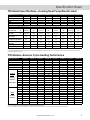
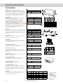
PTAC
Specification Sheet
FULL WARRANTY
• 1st Year
• 2nd- through 5th-Year—Sealed System
LIMITED WARRANTY
• 2nd- through 5th-Year—Parts
Added Great Standard Features
More Efficient
Quieter
Easier to Clean
Longer Lasting
UL
R
C
UL
R
Packaged Terminal Air
Conditioner and Heat Pump
No other unit in the industry offers so many extras
already built in as standard on every unit. Don’t
settle for anything less than the Amana® brand
Standard Advantage!
NEW Bent Coil Design. Our unique new bent condenser coil
maximizes airflow through the 25%-increased primary and
secondary coil surfaces, which further cools the refrigerant and
maximizes the sealed system life. The bent coil design also allows
us to maximize the fan slinger ring by adding side surface for the
condensate to be evaporated, reducing condensate over-flow.
Our bent coil technology raises the bar on America’s best PTAC
to a new level of excellence. Why bend the coil? Quite simply,
to get the maximum primary coil surface area possible into an
industry standard-sized wall sleeve. More primary coil surface
means more efficient heat transfer, lower system operating
temperatures, longer compressor life, better condensate
dispersion and sustainable high efficiencies.
NEW Quieter Operation. Our new PTAC has been redesigned
to be the quietest PTAC we’ve ever built! The new 9-bladed
condenser fan, additional copper refrigerant tubing, increased
copper tubing spacing, relocation of the reversing valve on
heat pumps, as well as other product enhancements, all equate
to a more reliable and much quieter operating unit.
NEW Forward-curved 9-Blade Fan. The new 9-blade, forward
curved, polypropylene condenser fan has been designed to
move more air more efficiently and with much less operating
sound than fans with fewer blades. The result is a more efficient
unit that will last longer and operate quietly.
NEW Removable Top Condenser Shroud. The removable top
of the new bent coil condenser shroud allows easy access to
clean the condenser coil and maintain the unit’s efficiency and
capacity. The removable top reduces cleaning time and cost. A
clean condenser coil extends compressor life.
NEW Pullout Filter Design. Our new 1-piece pullout filter design
allows easy access to clean or replace the filter. Just open
the front louver and pull out the filter. The universal filter design
allows for foolproof installation. The slide-out design also allows
for many optional approved filter media to be used, such as our
Activated Charcoal Filter Kit (CFK01B).
NEW Electronic Temperature Limiting. The new “B” series PTAC
has an enhanced electronic temperature limiter that allows you
to easily select any of the 4 pre-programmed room temperature
ranges by simply flipping an easily accessible set of switches.
Save energy and money by avoiding the extreme temperature
settings that can occur with guest operation.
NEW Deep Base Pan & Sub-cooler. The extra-deep base pan
holds additional condensate water and allows more of the coil
surface to be immersed in condensate water, which further
cools the refrigerant and maximizes heat transfer. The new
sub-cooler design is also in the deepened base pan and adds
additional heat transfer. The result is higher efficiency and a
cooler sealed system, which equates to longer life.
NEW Stonewood Room Front. Our new Stonewood room front
strikes the balance between attractive styling and practical
design. Distinctive contours and a modern appearance
enhance the character of even the most luxurious room, while
the sleek 7⅜” depth—one of the shallowest in the industry—
maximizes usable space for your guests.
NEW WS900D Wall Sleeve. The new Stonewood wall sleeve has
been designed using a technique to dramatically strengthen
and make the sleeve more rigid. The sleeve’s base pan has also
been enhanced by now being made of drawn steel, so the
sleeve has no corner seams that can break and potentially leak
if improperly installed. (This item purchased separately.)
www.amana-ptac.com
Specification Sheet
Standard Features
Energy Efficiencies. Our units’ high efficiencies can qualify you for many of the rebates offered by
electrical power companies. EERs up to 11.6 and COPs up to 3.3 keep energy consumption to a
minimum.
Quiet Operation. Our PTAC has been redesigned to be the quietest PTAC we’ve ever built. The
unit’s state-of-the-art design and construction provide a quiet environment, allowing guests to enjoy
peaceful, sleep-filled nights. Operating sound levels are further dampened when the unit is in “low fan”
mode of operation.
Increased Dehumidification Capacity. Maintain lower humidity levels in rooms while cooling them
without the need for expensive add-ons. As a result, guests feel more comfortable at higher
temperatures, thus reducing cooling costs, and increasing the life of your furniture, wall coverings, and
fixtures is extended, which means less replacement costs.
5-Year Warranty. Enjoy one of the most comprehensive warranties in the industry. Full 1-year warranty on
unit parts and labor; full 5-year warranty on the entire sealed system components; limited 2nd through
5th year parts-only warranty on functional components.
Condensate Dispersion System. Our condensate dispersion system removes condensate from indoor
cooling operation by throwing water directly on to the outdoor “bent” coil for rapid evaporation
and increased cooling efficiencies. The slinger ring on the new, enhanced 9-bladed fan draws water
up and into fan blades. This water is then atomized and evaporated into the atmosphere through
the condenser. Increased surface area from the unique “bent” coil design allow more water to get
evaporated on the sides of the coils and helps to minimize condensate run-off.
Front Desk Control. Obtain greater savings by centrally controlling units and eliminate wasted energy
generated by cooling and heating unoccupied rooms. Each unit has low voltage interface capability
with a field supplied front desk ON/OFF switch.
Freeze Protection. When the unit senses temperatures of 40 °F or below, the unit activates the fan motor
and either the electric resistance heater or the hydronic heater. This may help prevent bursting water
pipes or broken fixtures caused by freezing temperatures.
Easy To Use Controls. No complex controls to confuse your guests and create phone calls for your
manager. Controls are easy to read, understand and activate.
7⅜” Unit Front. Enhance valuable room space—the unit front has a sleek 7⅜” depth, one of the
shallowest silhouettes in the industry today. In addition, to inhibit guest-tampering, the front can be
secured to the chassis with a hidden screw.
Versatile Style. Our unit’s stylish design and neutral color make it compatible with virtually any room
décor or architectural design. The unit becomes less noticeable as it blends into the room’s color
scheme.
Easy to Service and LED Diagnostics. The main components are easily serviced and there is no guessing
to determine the problem with our easy-to-read diagnostics. For example: 2 blinks indicate a blown or
missing fuse while 1 blink every 5 seconds means the board is operating correctly. This diagnostic light is
visible by removing the front cover.
2
www.amana-ptac.com
Specification Sheet
Standard Features (cont.)
Stonewood Room Front. Our new Stonewood room front strikes the balance between attractive styling
and practical design. Distinctive contours and a modern appearance enhance the character of even
the most luxurious room, while the sleek 7⅜” depth—one of the shallowest in the industry—maximizes
usable space for your guests.
Remote Thermostat Control. Each unit is built to be operated from a remote-mounted thermostat, if
desired. Even if you start without a remote, you can take advantage of a built-in low-voltage power
source that accommodates a variety of manufacturer approved thermostat choices—manual, auto
changeover or programmable—at a later date.
Remote Temperature Sensing. Guests enjoy ultimate comfort with consistent climate control. When
the field-installed thermistor (RTS02) is used, the unit mounted thermostat is overridden to allow more
accurate, internal wall-sensing of room ambient temperature.
Extended Heat Pump Heating. The heat pump models will operate in the heat pump heating mode
down to as low as 24 °F outdoor ambient, providing additional hours of energy-saving operation.
Zero Floor Clearance. Unit can be installed flush to the finished floor, if desired. (Some accessories do not
have zero clearance).
30-Second Fan Off Delay. Fan continues to run 30 seconds after compressor has stopped in either
cooling or heat pump mode and after electric heat has been turned off. This improves efficiency by
dispersing the conditioned air on the coils into the room.
Compressor Lock-In. This feature helps prolong the life of the compressor by preventing short-cycling.
When the compressor is switched from Off to On because room temperature has risen or fallen below
the specified limit, it will remain on for at least 4 minutes. If the temperature set point is changed during
this 4 minutes, the lock-in feature is overridden.
Automatic Emergency Heat. No more “my unit is not heating” complaints during the middle of the night.
Heat pump units will automatically switch over to electric resistance heat if for any reason the heat
pump compressor system fails or if the heating load is greater than the unit capacity.
Fan Mode Switch. Take advantage of each unit’s dual options: select continuous fan operation or cycle
the fan ON and OFF with the thermostat.
Reduced Outdoor Sound Transmission. With our STC (Sound Transmission Coefficient) rating of 27, we
keep outdoor sounds out-of-doors. By installing the optional STC 30 Rating Accessory Kit, ratings can be
increased to STC 30, thereby meeting or exceeding most ratings requirements. (Kit ordered separately.)
Hidden Ventilation Control. The ventilation control lever is hidden from the occupant's view to allow you
to manage ventilation requirements.
Optional Accessory
Wall Sleeve (14⅛” x 42” x 161/16”). No more worries about changing out non-standard sleeves that do
not accommodate the bulk of what the industry has to offer. Our wall sleeve is an industry-standard size
of 14⅛” deep x 42” wide x 161/16” high. (Please Note: Wall Sleeve must be ordered separately.)
www.amana-ptac.com
3
Specification Sheet
PTC Model Specifications—Cooling/Electric Heat
Model 1, 7, 9, 10
PTC073B**AJ
PTC074B**AE
PTC123B**AJ
PTC124B**AE
PTC153B**AJ
PTC154B**AE
Voltage 1, 3, 11
230/208
265
230/208
265
230/208
265
230/208
265
Capacity (BTUH)
PTC093B**AJ PTC094B**AE
7,100/6,900
7,100
9,100/8,900
9,100
12,000/11,900
12,000
14,000/13,900
14,000
Amps
2.8/3.0
2.3
3.7/3.8
3.0
4.6/5.0
4.3
6.3/6.9
5.9
Watts
610/595
610
790/775
790
1,110/1,100
1,130
1,470/1,450
1,470
11.6
11.6
11.5
11.5
10.8
10.8
9.5
9.5
3.6
245
220
265
230
5.1
245/240
220/205
265/260
230/215
4.4
245
220
265
230
6.4
325/315
250/229
345/335
265/235
5.7
325
250
345
265
8.8
325/315
250/220
345/335
265/235
7.7
325
250
345
265
65*
65*
65*
70*
70*
70*
70*
65*
65*
65*
70*
70*
70*
70*
1.6
2.6
2.6
3.5
3.5
4.4
4.4
90
105
95
110
95
110
105
120
105
120
110
125
110
125
EER
Unit without Electric Heater
Min. Circuit Ampacity 2, 4
4.0
CFM
245/240
High
Low
(Cool/Wet Coil)
220/205
265/260
CFM
High
Low
230/215
(Dry Coil)
Ventilated Air, CFM
65*
(Fan Only)*
Ventilated Air, CFM
65*
(Compressor & Fan)*
Dehumidification
1.6
(Pints/Hr.)
Net Weight (lbs.)
90
Shipping Weight (lbs.)
105
*Approximately 95 CFM with optional power vent kit. Actual vent CFM performance will vary due to application and installation conditions.
PTC and PTH Models—Electric Heater Performance
See page 11 for Power
Cord Configuration
(Primary Heating for PTC Models; Auxiliary Heating for PTH Models)
Electric
Heater
Size (kW)
No. of
Stages
230/208V
2.5/2.0
1
Nominal Heating
BTUH
BTUH
BTUH
@ 230V @ 208V @ 265V
8,500
6,800
--
230/208V
3.5/2.9
1
12,000
9,900
230/208V
Voltage
Total Watts6
Total Amps8
Minimum
Circuit
Ampacity2
Overcurrent
Protection4
Power Cord
2,650/2,140
11.5/10.2
14.2
15
6 - 15 P
--
3,650/3,040
15.8/14.5
19.6
20
6 - 20 P
6 - 30 P
5.0/4.1
1*
17,100
14,000
--
5,150/4,240
22.3/20.3
27.7
30
265V
2.5
1
--
--
8,500
2,650
10.0
12.4
15
7 - 20 P
265V
3.7
1
--
--
12,600
3,850
14.6
18.1
20
7 - 20 P
265V
5.0
1*
--
--
17,100
5,150
19.5
24.2
25
7 - 30 P
*PTH/PTC09*B50*E/J has the same air flow as a PTC/PTH12*B***E/J. (Not available on 7,000 BTU models.)
Hydronic Heat Models
Hydronic Models/Hot Water & Steam Heating
These models are shipped without a chassis front or
electric heat, and they have an additional relay and
40VA transformer for water or steam valve operation.
Also available is Hydronic with Powered Vent and
Hydronic with Powered Door. See Model Nomenclature
for Special Feature Codes for these models. See page
7 for hydronic accessories.
Hydronic with Manual Door
Model Number Voltage Capacity
Cooling Capacity
EER
PTC093B00HE
230/208
9,100/8,900
11.6
PTC123B00HE
230/208
12,000/11,900
10.8
PTC153B00HE
230/208
14,200/14,000
9.5
PTC094B00HE
265
9,100
11.6
PTC124B00HE
265
12,200
10.8
PTC154B00HE
265
14,200
9.5
NOTES:
1. All 265v models must use our subbase (PTSB4**E) or an Amana® brand hard wire kit (PTPWHWK4)
2. Minimum branch circuit ampacity ratings conform to the National Electric Code. However, local codes should apply.
3. Minimum voltage on 230/208 volt models is 197 volts; maximum is 253 volts. Minimum voltage on 265 volt models is 238.5 volts; maximum is 291.5 volts.
4. Overcurrent protection for all units without electric heaters is 15 amps. Overcurrent protection on 265 volt models must be cartridge-style time delay fuses (included and
factory-installed on Amana® brand all 265 volt chassis).
5. Heating capacity and efficiency is based on unit operation without condensate pump. Unit automatically switches to electric heat at approximately 24 °F outdoor
ambient.
6. Total watts for 12,000 and 15,000 Btuh models. Subtract 70 watts for PT07/09*B**AE.
7. Please specify 2-digit heater kW size to complete model number.
8. Total amps for 12,000 and 15,000 Btuh models; subtract 0.2 amps for PT07/09*B*AE.
9. Refrigerant used in all systems is R-22.
10. All units meet or exceed ASHRAE 90.1 standards.
11. All units less than 250 volts have a Leak Current Detector Interrupter (LCDI) power cord and meet UL 484 standards.
4
www.amana-ptac.com
Specification Sheet
PTH Model Specifications—Cooling/Heat Pump/Electric Heat
Model 1, 7, 9, 10
PTH073B**AJ PTH074B**AE PTH093B**AJ PTH094B**AE PTH123B**AJ PTH124B**AE PTH153B**AJ PTH154B**AE
Voltage 1, 3, 11
230/208
265
230/208
265
230/208
265
230/208
265
12,000/11,800
12,000
14,000/13,900
14,000
Capacity (BTUH)
7,000/6,800
7,000
9,100/8,900
9,100
Amps
2.8/3.0
2.3
3.5/3.8
3.0
4.6/5.0
4.3
6.3/6.9
5.9
Watts
605/585
605
790/775
790
1,110/1,090
1,110
1,505/1,495
1,505
EER
11.6
11.6
11.5
11.5
10.8
10.8
9.3
9.3
Units without Electric Heater
4.0
3.6
5.1
4.4
6.4
5.7
8.8
7.7
Min. Circuit Ampacity 2, 4
245/240
245
245/240
245
325/315
325
325/315
325
CFM
High
Low
(Cool/Wet Coil)
220/205
220
220/205
220
250/229
250
250/220
250
265/260
265
265/260
265
345/335
345
345/335
345
CFM
High
Low
230/215
230
230/215
230
265/235
265
265/235
265
(Dry Coil)
Ventilated Air, CFM
65*
65*
65*
65*
70*
70*
70*
70*
(Fan Only)*
Ventilated Air, CFM
65*
65*
65*
65*
70*
70*
70*
70*
(Compressor and Fan)*
Dehumidification
1.6
1.6
2.6
2.6
3.5
3.5
4.4
4.4
(Pints/Hr.)
Net Weight (lbs.)
95
95
100
100
110
110
115
115
Shipping Weight (lbs.)
110
110
115
115
125
125
130
130
* Approximately 95 CFM with optional power vent kit. Actual vent CFM performance will vary due to application and installation conditions.
**EER - Energy Efficiency Rating per Air Conditioning & Refrigeration Institute (ARI) Test Procedures and Canadian Standards Association
(CSA) EEV Test Procedures
PTH Models—Reverse Cycle Heating Performance
Heating Capacity1
BTUH5
Amps
Watts
COP5
CFM (Dry)
62 °F
57 °F
52 °F
Heating
(BTUH) 5
47 °F
COP*
Outdoor
42 °F
Ambient
37 °F
Rating Point
32 °F
27 °F
24 °F
62 °F
57 °F
52 °F
Watts
47 °F
42 °F
Outdoor
37 °F
Ambient
32 °F
27 °F
24 °F
PTH073B**AJ PTH074B**AE PTH093B**AJ PTH094B**AE PTH123B**AJ PTH124B**AE PTH153B**AJ PTH154B**AE
6,200/6,000
6,200
8,200/8,000
8,200
10,800/10,600
10,800
13,300/13,200
13,300
2.6/3.0
2.2
3.2/3.6
2.6
4.5/5.1
3.9
5.7/6.3
5.4
550/530
550
750/730
750
1,020/1,000
1,020
1,340/1,330
1,340
3.3
3.3
3.2
3.2
3.1
3.1
2.9
2.9
235/230
235
235/230
230
310/290
310
345/335
345
7,200/7,000
7,200
9,800/9,600
9,800
13,000/12,800
13,000
15,800/15,700
15,800
6,900/6,700
6,900
9,300/9,100
9,300
12,300/12,100
12,300
15,000/14,900
15,000
6,500/6,300
6,500
8,700/8,500
8,700
11,600/11,400
11,600
14,200/14,100
14,200
6,200/6,000
6,200
8,200/8,000
8,200
10,800/10,600
10,800
13,300/13,200
13,300
3.3/3.3
3.3
3.2/3.2
3.2
3.1/3.1
3.1
2.9/2.9
2.9
5,900/5,700
5,900
7,700/7,500
7,700
10,100/9,900
10,100
12,500/12,400
12,500
5,600/5,400
5,500
7,200/7,000
7,200
9,400/9,200
9,400
11,700/11,600
11,700
5,300/5,100
5,200
6,700/6,500
6,700
8,600/8,400
8,600
10,800/10,700
10,800
5,000/4,800
5,000
6,200/6,000
6,200
7,900/7,700
7,900
10,000/9,900
10,000
4,800/4,600
4,800
5,900/5,700
5,900
7,500/7,300
7,500
9,500/9,400
9,500
580/560
580
810/790
810
1,120/1,100
1,120
1,465/1,455
1,465
575/555
575
800/780
800
1,090/1,075
1,090
1,440/1,430
1,440
555/535
555
775/755
775
1,060/1,045
1,060
1,405/1,395
1,405
550/530
550
750/730
750
1,020/1,005
1,020
1,340/1,330
1,340
540/525
560
730/710
730
985/970
985
1,325/1,315
1,325
530/515
545
705/685
705
950/935
950
1,285/1,275
1,285
515/500
535
690/670
690
900/885
900
1,240/1,230
1,240
505/490
525
660/640
660
855/840
855
1,190/1,180
1,190
500/485
520
640/620
640
830/815
830
1,180/1,170
1,180
See page 4 for Notes and Auxiliary Electric Heater Performance
COP - Coefficiency of Performance per ARI Test Procedures Units are rated for capacities and efficiencies.
www.amana-ptac.com
5
Specification Sheet
Wall Sleeve 14⅛” (D) x 42” (W) x 161/16” (H)
Our insulated, stonewood beige metal sleeves with industrystandard dimensions are shipped with a weather board for use
during construction. The WS900D is an industry-standard depth
of 14⅛”. The extra-deep sleeves can be custom ordered starting
at 16” to 24” (D) in 1” increments. Sleeves may be shipped
separately to allow for installation during construction.
Outdoor Grilles
Available in stamped-aluminum or architecturally louvered for
application with a WS900D wall sleeve.
AGK—Extruded aluminum architectural grille available with
anodized aluminum finish and a baked-on paint finish for
durability. Choose from 3 stock colors or a custom color.
CB (Clear Anodized), DB (Dark Brown/Bronze), TB (Stonewood
Beige), WB (White), SB (Special/Custom Colors)
PGK—One-piece injection molded grille using a polymer blend
of engineered thermoplastic high-impact strength material with
chemical resistance and an exterior UV protective coating.
Choose from 3 stock colors. DB (Dark Brown/Bronze), TB
(Stonewood Beige), WB (White)
WS900D
Standard 14⅛” Depth
WS9**D1
Extra Deep (16” to 24”)
161/16"
Accessories
** Depth in inches
42"
14
Standard Outdoor Grille
SGK01B
Single Pack
Architectural Grille
Subbase Kit
The fully skirted subbase conceals wiring while providing
strong support, if needed. Plug-in receptacle and field-wiring
access speeds installation. Electrical accessories, such as fuse
holders, circuit breakers and disconnect switches, meet N.E.C.
requirements.
AGK01*B
Single Pack
PGK01*B
Single Pack
PTSB320E
PTSB330E
PTSB420E
PTSB430E
PTSB000E
230/208V 15/20A
230/208V 30A
265V 15/20A
265V 25A
Non-electrical
AGK
or
PGK
Optional
Fuse Holder
Location
Optional
Power Switch and Circuit Breaker
Location
Power Receptacle
Skirting
Hard Wire Kit (not shown)
Used to permanently wire to the chassis when a standard
subbase and power cord are not utilized.
PTPWHWK4
Fuse Holder Kit
Cartridge-style fuses can be installed in the fuse holder for
use in the subbase or chassis. Available in 15, 20 and 30 amp
(included on 265-volt unit).
Subbase Extension Cover Kit
Converts older 30-amp subbases to allow for installation of the
larger 30-amp LCDI power cord and plugs.
Circuit Breaker Kit (230/208V only)
The circuit breaker kit, available in 15, 20 or 30 amp, can
be used with Amana® brand subbases. It gives overcurrent
protection, and its location allows you to turn the unit on or off
without tools.
Wire Harness Kit (not shown)
For quick connections of the remote thermostat or front desk
with jumpers and connectors.
Remote Temperature Sensor
Allows inexpensive, low-voltage temperature sensing on the
internal wall for more accurate temperature control.
Thermostats
The following thermostats offer remote control. Any thermostat
other than those listed must be submitted to Goodman
Company, L.P., for approval prior to use.
Subbase Box Assembly
230/208V 15A
230/208V 20A
FHK330C
230/208V 30A
10 Pack
CBK3**C
Circuit Breaker Kit
PWHK01C
Wire Harness Kit
STC101A
Power Disconnect Switch (not shown)
The PSHW**A power disconnect switch can be used for
265-volt or 230/208-volt physical disconnect, where required
by local codes. The switch is rated at 30-amp capacity. The
switch is for use with and Amana® brand standard subbases or
PTPWHWK4 Hard Wire Kit.
Hard Wire Kit
FHK320C
SBEC10A
Skirting
Leveling Legs
FHK315C
RTS02
STC 30 Rating Accessory Kit (not shown)
Raises sound ratings from 27 to 30 to meet or exceed most
sound test requirements.
6
⅛"
Remote Temperature Sensor
10 Pack
PSHW03A
230/208V
PSHW04A
265V
Heat
Cool
Stages Stages Display
C5200609
1*
1
Mech.
D9945801
2**
1
Mech.
1246005/6
1*
1
Mech.
1246001
1*
1
Digital
1246003
2**
1
Digital
1246004
2**
1
Digital
1241501
2**
1
Digital
Model
www.amana-ptac.com
Shape &
Orientation
Manual
Round
Manual
Rect./Horiz.
Manual
Rect./V or H
Manual
Rect./Horiz.
Manual
Rect./Horiz.
Program
Rect./Horiz.
Auto Change Rect./Vert.
Type
* PTC Models Only
** PTC and PTH Models
Specification Sheet
Condensate Drain Kit
Attaches to the wall sleeve base pan for controlled internal or
external disposal of condensate.
Condensate Drain Kit
(use with WS900D)
Condensate Drain Kit (use with
WS900B & extra deep wall sleeves)
DK900D
DK9001D
Security Key Locks (not shown)
In conjunction with the tamper-resistant front, the installation of
Amana® brand security key locks prevents tampering of the
controls used to set temperature, heating and cooling functions.
U.L. approved for institutional use only.
Remote Escutcheon Kit (not shown)
Optional kit for use with units controlled via a wall thermostat.
Replaces knob controls for units operated by wall thermostat.
Condenser Baffle Kit
For use on non-baffled grilles. These deflectors direct the air in
toward the center and away from the inlet to prevent
recirculation of the hot condenser air.
KL03B
Security Key Lock
REK10B
Remote Escutcheon Kit (10-pack)
DGK1B
Condenser Baffle Kit
DK900D
Each kit contains 80 wires and wire nuts, enough
to attach a thermostat and one additional
accessory to 10 PTAC units. Wires come in
assorted colors for easy attachement.
Condenser Baffles
Condenser
Power Vent Kit (not shown)
Installation of Power Vent increases CFM up to approximately 95.
Vent door will automatically close when unit fan is off.
Power Door Kit (not shown)
Vent door will automatically open when unit fan is on.
Hydronic Transformer Relay Kit (not shown)
Add-on kit that allows field conversion of a standard PTC unit to a
hydronic unit.
Hydronic Heat Kit
Add-on kits fit all units allowing the addition of hydronic water or
hydronic steam heat to cooling and heating units. The kits feature
left- or right-hand piping. Unit retains complete service access
with a kit installed.
Hydronic Valves (not shown)
Water and steam valves are available for use with the HWK03
(water) and HVK03 (steam) heat kits. (See Architects and
Engineers Manual for specifications.)
PVK3A
230/208V
PVK4A
265V
PDK3A
230/208V
PDK4A
265V
Basepan
Hydronic Heat Kit-Top View
5-1/2"
HTK3A
230/208V
HTK4A
265V
HWK03
Hydronic Water Kit
HVK03
Hydronic Steam Kit
15/32"
2 places
2-3/4"
2 places
Hydronic Air
Discharge
NEW! Replacement Charcoal Filter Kit (not shown)
Absorbs airborne odors caused by cigarette, pipe or cigar smoke
and odors caused by mold, mildew, etc. Filters are made of
polyester fibers coated with activated charcoal and are
individually wrapped. This filters are permanent and can be
washed or cleaned. Call your Amana® brand PTAC sales person
for details. 10 filters per pack.
Unit Controls
Compartment
Hydronic Heat Kit-Right View
Hot Water Inlet / Outlet Connections
Steam
Inlet
/ Outlet Connection
Outlet
Connection
VS2WNCA*
2-way/24V/NC/Steam
VS2WNOA*
2-way/24V/NO/Steam
VW2WNCA*
2-way/24V/NC/End Switch
VW2WNOA*
2-way/24V/NO/End Switch
CDP302
230/208V
CDP402
265V
Steam/Water
Coil Position
Hot Water Inlet / Outlet Connections
SteamSteam
Inlet /Inlet
Outlet Connections
16-3/4"
8-1/4"
20-3/16"
2-1/8"
53"
Hydronic Air
Inlet
Hydronic Heat Kit-Side View
3" +1/8"
-0"
Top of Wall Sleeve
4-1/8"
Hydronic Front
Wall Sleeve
Spare Filters (not shown)
Helps keep dirt and lint out of the air and off the coil, thus
increasing the unit's efficiency. Amana® brand filters are easy to
remove, wash and replace.
3-1/4"
1-7/8"
VW3WNC2B*
3-way/24V/NC/NO/End Switch
* Poptop Actuator
Condensate Removal Pump (not shown)
Can be field installed. Assists in removing condensate developed
by heat pump operation and transfers it to indoor coil to dissipate
into room while adding humidity to the room.
1-7/8"
PTAC UNIT WALL SLEEVE
3-1/4"
FK10A
Filters (10-pack) - A Series
FK10B
Filters (10-pack) - B Series
CFK10A
Charcoal Filters
(10-pack) - A Series
CFK10B
Charcoal Filters
(10-pack) - B Series
10-13/16"
Main Duct Kit
TRANSITION
Duct Extension Kit
Extends air distribution to an adjoining room. Consists of a main
duct for the room of origin and an extension duct to reach the
adjoining room and terminal duct.
Heater Kit—For Heater-less Units Only (not shown)
Optional 1.5kW heater kits are available for use only with models
originally shipped without electric heat. Ask salesperson for details.
Main Duct
EDK02B
Extension Duct
TDK02
Terminal Duct
PTDK01A
Transition Duct Only
Full Load Amps
(incl. fan)
Min. Ampacity
Fuse Size
Model
Nominal BTUs
230V
208V
265V
1,500
All
1,500
1,200
7K & 9K
6.9
6.2
6.1
12K & 15K
7.1
6.4
6.3
7K & 9K
8.6
8.6
7.5
12K & 15K
8.8
8.8
7.7
All
15
15
15
www.amana-ptac.com
BAFFLES
Extension Duct Kit
MDK02B
Rated Watts
Toe Plate
0" - 3.0" Long
Bottom of Wall Sleeve
Terminal Duct Kit
7
Specification Sheet
Furnish and install air cooled through the wall package terminal air conditioners (heat
pumps). Units are rated in accordance with the ARI (Air Conditioning & Refrigeration
Institute) Standards 310/380-93, CSA (Canadian Standards Association) EEV
certification programs and listed by U. L. (Underwriters Laboratories).
Ratings
Each unit must meet the following specifications:
ARI rating of _________BTUH cooling (and _________
BTUH reverse cycle heating with a COP of ________
_ at 47° F O.D.)
Electric resistance heat of _________ BTUH. Total
Amp draw must be of _________ and _________
Watts at _________ volts.
The unit must remove a minimum of _________
pints of moisture per hour when operated at rating
conditions. The EER must be a minimum of _______
__ EER.
Unit Chassis
Each unit must be slide out design shipped with
room cabinet front installed. Unit chassis must
have the ability to be installed with 0 clearance
from finished floor. An electrical power cord
must be included with chassis and installed by
the manufacturer to assure proper NEMA 6 or 7
configuration and UL-approved length. Units less
than 250 volts must also have a LCDI power cord.
Unit must be tested for conformance to ASTME
water infiltration specification ASTME 331-86, which
ensures no water infiltration when tested at 8" rain
per hour at 63 mph wind for 15 minutes.
Room Cabinet
The monochromatic front of the room cabinet
must be able to be field-secured to chassis to inhibit
tampering. Filter must be accessible without removing
room front. Cabinet depth must not exceed 7⅜” to
minimize unit’s impact on room space.
Coils
Unit’s coils must have rifled copper tubing expanded
into rippled-edge louvered aluminum fins.
Heat Pumps
Each unit must include a changeover thermistor
that senses an outside ambient switch-over
temperature as low as 24 °F, lock-open refrigerant
reversing valve during heat pump operation,
temperature-activated defrost drain and
automatic emergency heat operation to override
the heat pump’s change-over thermostat and
bring on electric resistance heaters in the event
of a sealed system failure. Unit must not operate
compressor and electric heaters simultaneously.
Unit Controls
The unit’s controls must be completely wired and
accessible from the top. Controls must include
high and low fan speeds for both cooling,
heating, fan-only operation and an OFF position.
Other unit controls must include a concealed
ventilation control to allow the introduction of
outside air into the room, a concealed fan mode
switch to allow the owner to preset for either
continuous fan or thermostatically cycled fan
operation. Additionally, the following controls are
to be included as standard on all units:
• Compressor restart delay
• Random restart circuit
• Front desk control capabilities
• Automatic room freeze protection
• Remote control capability
• Electronic temperature limiter
• Remote temperature sensing capability
• Load shedding capability
Evaporator/Condenser Fans
Direct drive with a permanent, split-capacitor,
two-speed motor. Condensate must be
directed onto the bent condenser coil to aid in
evaporation and removal. Condenser fan must be
a forward-curved, 9-bladed, propeller type with
a slinger ring, and the evaporator fan must be
blower type.
Air Discharge
Must be a sloped surface so that obstructions
cannot be placed on the unit. Discharge
conditioned air can be directed into the
room at an angle of 15 or 40 degrees from the
vertical position. The discharge grille must be
of polycarbonate material to resist bending,
cracking, rusting and corrosion.
Warranty
The warranty is for Full One Year on the entire unit;
Full Second through Fifth Year on the entire sealed
refrigerant system components; Limited Second
through Fifth Year on functional parts only.
Compressor
The compressor must be hermetically sealed,
internally isolated, rotary-type and permanently
mounted on rubber isolators. No removal or
adjustment of compressor hold-down bolts is to be
required during installation.
8
www.amana-ptac.com
Specification Sheet
New installations typically require a minimum of WS900D wall sleeve and an outdoor grille.
Wall Sleeves (WS900D)
The wall sleeve must be industry-accepted
dimensions: 14⅛” depth x 42” width x 161/16” height
and constructed of G90 HDG galvanized steel
with a baked corrosion-inhibiting urethane primer
and baked-polyester topcoat enamel. Sleeve
must be insulated and shipped with a weather
resistant rear closure panel installed.
Outdoor Grilles
Outdoor grille must be architecturally extruded,
louvered aluminum (AGK01*B), one-piece
polymer-blend injection molded louver (PGK01*B)
or standard stamped aluminum (SGK**B). All
other grilles must be submitted to the PTAC
manufacturer for feasibility, airflow characteristics
and compliance with UL regulations, where
necessary.
The optional accessories listed below perform specific functions required in some installations.
Remote Temperature Sensor (RTS02)
A field-installed thermistor will override the
unit-mounted thermostat to allow more
accurate, internal wall-sensing of room-ambient
temperature. All other modes and functions
remain at the PTAC unit.
Condensate Drain Kit (DK900D)
Attaches to the bottom of the wall sleeve for
directional-controlled internal or external disposal
of condensate, defrost or rain water.
Subbase Kit (PTSB***E)
Necessary for U.L. listing requirements for 265V
units (Hard Wire Kit may be substituted for Subbase
kit). Optional for 230/208V units. Must be prewired to facilitate field-electrical connections and
include a NEMA 6 or 7 configuration electrical
receptacle. It must have 2 leveling screws for
sleeve support and accurate unit leveling during
installation. Locations for field installation of
physical disconnect switches, cartridge-style fuse
holders and circuit breakers must be provided.
Side-skirts must be provided with subbases.
(PTSB000E Non-Electrical Subbase available.)
Power Vent & Damper
Must be provided to maximize ventilation air
intake to up to approximately 95 CFM. Power vent
must be off and damper door closed when unit
fan is de-energized.
Fuse Holder (included in 265V chassis)
Must be installed either in the unit or the subbase
and must match the electrical requirements of the
chassis.
Security Key Locks (KL03B)
Must be installed to prevent tampering of the unit
controls. Unit room cabinet must also be secured
to the chassis with field supplied screws. U.L.approved for institutional use only.
Disconnect Switch
Power disconnect switch must be installed in
subbase for use as a physical disconnect, where
required by local codes.
Duct Kits (MDK02B, EDK02B, TDK02)
Three kits must be supplied to provide ducted,
conditioned air into a second room: a main duct
kit, an extension duct kit and a terminal duct kit.
Hydronic Heat Kit
Is required for heating functions instead of electric
resistance heaters. Unit must retain complete
service access with the kit installed. Proper water
or steam valves must be used.
Condensate Removal Pump (Heat Pumps only)
Must be installed to assist in removing the
condensate developed by the heat pump
operation and transfer it to the indoor coil to
dissipate into the room, adding humidity to the
room.
Circuit Breaker Kit
Must be installed in subbase to provide
overcurrent protection for proper 230/208V
amperage. Can also be used as a physical
disconnect where local codes permit for 230/208
voltage.
Hard Wire Kit
Must be used to permanently wire chassis for hard
wire purposes. (For 265V units, Hard Wire Kit may
be substituted with Subbase Kit.)
Charcoal Filter Kit -- Optional (CFK10B)
Amana® brand Activated Charcoal filters absorb
odors caused by cigarette, pipe or cigar smoke
and airborne odors caused by mold, mildew,
etc. These replacement filters are polyester
fibers coated with activated charcoal. Each
filter is individually wrapped to assure maximum
absorption and durability when installed. (10 filters
per kit.)
Thermostats
A manufacturer-approved manual, auto
changeover or programmable thermostat must
be installed to provide full remote operation of the
chassis. A Remote Escutcheon Kit must be used to
indicate remote operation.
www.amana-ptac.com
9
Specification Sheet
Unit with Accessory Wall Sleeve and Subbase Accessory
42"
Top View
40"
6 - 1 / 8"
9 - 9 / 16"
24 - 5 / 16"
1"
Location of external drain holes
on bottom flange of Wall Sleeve
Air
Flow
1"
Air
Flow
Air
Flow
Control
Door
Air Discharge Grille
3
AIR DISCHARGE GRILLE IS
REVERSIBLE TO PROVIDE EITHER
15° OR 40° DISCHARGE ANGLE
3" Clearance
to side walls
"
7/8"
STAMPED GRILLE
21-1/2"
14-1/8"
WALL SLEEVE
7-3/8"
Right View
1-3/8"
ARCH GRILLE
15°
40°
16-1/16"
HINGED
CONTROL
DOOR
OPTIONAL
SUBBASE
4"
13/16"
1 -3 /8"
11-3/8"
13/16"
1/2" O.D.
COPPER
DRAIN TUBE
2-3/4"
42"
Front View
58” LCDI CORD
SET 230V/208V
UNIT*
LEFT
R I GHT
16-1/16"
2-5/8"
3-1/4"
MIN
2"
MAX
1" AND 3/4" CONCENTRIC KNOCKOUTS BACK
& BOTTOM OF SUBBASE (ELECTRICAL ONLY)
10
www.amana-ptac.com
58" CORD
SET 230V/208V UNIT*
18" CORD
SET
265V UNIT*
Specification Sheet
Framing for Accessory Wall Sleeve (WS900D)
JACK STUDS
Alternative
Fastening Method
(Field Supplied)
HEADER - 4" x 4" OR
DOUBLE 2"x 4" ON EDGE
MAIN STUD
Wood Screw
Toggle Bolt
Expansion
Anchor Bolt
Mounting
Holes
(Drilled by
Installer)
16 1/4"
MIN
42
ADJUST FRAMING TO
SECURE THIS DIMENSION
1/4
"
JACK STUD
Plastic
Anchor
Wall Sleeve must
extend a minimum of
¼” beyond outside
wall to allow for proper
caulking.
Screws
CRIPPLE
FINISHED FLOOR
SUB-FLOOR
INSTALLATION NOTES
1. If Subbase (PTSB***E) is installed, allow minimum
3¼” height clearance and maximum 5” height
clearance between wall sleeve and floor; allow
minimum 2¾” protrusion from a finished wall. See
Note 4 if using hydronic units.
4.
5.
For U.L. approval, 265V units must use Amana®
brand Subbase (PTSB***E) or Amana® brand Hard
Wire Kit (PTPWHWK4). Overcurrent protection on
265V units must be by cartridge-style time delay
fuses, which are included and factory-installed on
the Amana® brand 265V chassis.
Power Cord Plugs
20 amp
15 amp
30 amp
277V Rating Power Cord Plugs
NEMA 7 Configuration
W
3.
Drain Kit (DK900D) shipped separately. Can be
mounted either right side, left side or bottom of
sleeve. If mounted to bottom of sleeve, allow 2”
height clearance from floor to bottom of sleeve.
W = 42¼"
250V Rating Power Cord Plugs with LCDI Device
NEMA 6 Configuration
G
2.
H = 16¼"
Wall Sleeve Opening Height
Should Be Squared with
Wall Sleeve Opening Width
W
When installed in an opening, the Wall Sleeve
must be horizontally level (side-to-side) and
pitched ¼ bubble to the outside. (NOTE: To ensure
unit’s maximum efficiency, DO NOT over- or underpitch.)
G
FASTENING WALL SLEEVE
20 amp
30 amp
Power Receptacle Configuration
If Hydronic Kit (HWK03 or HVK03) is installed, Wall
Sleeve must extend exactly 3" into the room from
the finished interior wall. If using the Amana®
brand Subbase (PTSB***E), only the minimum 3¼”
height clearance between wall sleeve and floor is
permissible.
G
NEMA6-15R; 250V receptacle,
used on 230/208V units
G
NEMA6-20R; 250V receptacle,
used on 230/208V units
G
G
W
G
If Duct Kit (MDK02B) is installed, allow a minimum of
2⅜” into the room from the finished interior wall.
NEMA6-30R; 250V receptacle,
used on 230/208V units
NEMA7-20R; 277V receptacle,
used on 265V units
NEMA7-30R; 277V receptacle,
used on 265V units
All units come with factory-installed power cords.
All units less than 250 volts come with LCDI device.
www.amana-ptac.com
11
Specification Sheet
Nomenclature
PT
C
09
3
B
35 A
*
Engineering Design Series
Package
Terminal
E = Standard Control Unit (265 volt only)
G = DigiSmart LED Unit (265 volt only)
H = Premium DigiSmart LED Unit (265 volt only)
J = Standard Control w/LCDI cord (230/208 or 115 volt only)
K = DigiSmart LED w/LCDI cord (230/208 or 115 volt only)
L = Premium DigiSmart LED w/LCDI (230/208 or 115 volt only)
Model Type
C = Cooler
H = Heat Pump
Special Feature Code
Nominal Cooling Capacity
07 = 7,000 BTUH
09 = 9,000 BTUH
12 = 12,000 BTUH
15 = 15,000 BTUH
Major
Design
Series
Voltage
2 = 115v 60 Hz
3 = 230/208v 60 Hz 1 PH
4 = 265v 60 Hz 1 PH
5 = 240/220v 50 Hz 1 PH
A
B
C
D
E
F
G
H
I
J
= Standard Model
= Power Vent
= Seacoast Model
= Condenser Disposal Pump
= Hydronic w/Power Vent & Door
= Hydronic w/Power Door
= Hydronic w/Manual Door
= Power Door
= Condenser Pump & Power Vent
= Condenser Pump & Power Door
Heater Sizes
00
15
25
35
= 0.0 KW
= 1.5 KW
= 2.5 KW
= 3.5 KW (230V-208V) Models
= 3.7 KW (265V) Models
= 5.0 KW
50
Pull-out Easy Access Filter
Maintaining the unit’s efficiency while saving time and money is easy. The filter is easily accessed
for cleaning or replacement without removing the unit front.
Step 1: Open the intake grille louver.
Step 2: Pull the filter up and out.
Amana® is a trademark of Maytag Corporation and used under license to Goodman Company, L.P. All rights reserved.
Our continuing commitment to quality products may mean a change in specifications without notice.
Date: 9/04
Supercedes 6/04
Copyright © 2004 Goodman Company, L.P. · Houston, Texas · Printed in U.S.A
Form: PDB-PTAC
12
www.amana-ptac.com