1
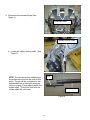
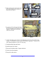
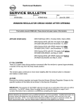
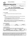
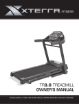
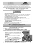
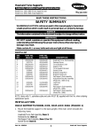
Classification:
Reference:
BT05-040a
Date:
NTB05-077a
September 16, 2005
2005 FRONTIER, XTERRA, PATHFINDER, 2004-2005 TITAN AND
ARMADA; FRONT PASSENGER FOLD FLAT SEAT MANUAL
RECLINER INOPERATIVE
The Applied Vehicle and Service Procedure sections of this bulletin have been amended.
Please discard all other copies.
APPLIED VEHICLE(S):
2005 Frontier (D40),
2005 Xterra (N50),
2005 Pathfinder (R51)
2004-2005 Titan (A60),
2004-2005 Armada (TA60)
IF YOU CONFIRM
The passenger seat does not recline or tilt forward when lifting UP on the recliner handle.
ACTION
Remove the seat and use a steel split spring pin (roll pin) to repair shaft of inboard
recliner mechanism.
This will prevent the inboard recliner mechanism pin from slipping inside the shaft.
CLAIMS INFORMATION
Submit a Primary Operation (PO) line claim using the following claims coding:
DESCRIPTION
OP
CODE
SYM
DIA
FRT
Repair Front Passenger Seat Manual
Recliner
VX49AA
ZE
32
0.5 hrs
PARTS INFORMATION
DESCRIPTION
Steel split spring pin* (roll pin), Size:
5/32 inch (3.96 mm) diameter X ½ inch (12.7 mm) long.
(Use McMaster–Carr part number 98296A892 or equivalent.)
PART #
QUANTITY
Local source
2
*Do not claim billing for the pin, it is considered as a shop supply.
IMPORTANT: The purpose of “ACTIONS” (above) is to give you a quick idea of the work you will be
performing. You MUST closely follow the entire Service Procedure (starting on page 2) as it
contains information that is essential to successfully completing this repair.
Nissan Bulletins are intended for use by qualified technicians, not 'do-it-yourselfers'. Qualified technicians are
properly trained individuals who have the equipment, tools, safety instruction, and know-how to do a job
properly and safely. NOTE: If you believe that a described condition may apply to a particular vehicle, DO
NOT assume that it does. See your Nissan dealer to determine if this applies to your vehicle.
1/5
SERVICE PROCEDURE
1. Preparation for seat removal.
Refer to the Electronic Service Manual (ESM), section SE, for seat removal
information. Make sure to follow all WARNINGS and CAUTIONS.
Before disconnecting any SRS connectors:
A. Write down all radio station presets.
Presets
A
B
C
1
2
3
4
5
6
B. Disconnect both battery cables (negative cable first).
C. Wait at least 3 minutes after the battery cables are disconnected.
2. Remove the seat from the vehicle.
NOTE : Place the seat on a clean surface to prevent dirt/and or scuff marks.
3. Align inboard and outboard recliner devices. Inboard recliner device is on the left side of
the seat and the outboard recliner device is on the right side.
A. Use release handle and recline seat
forward until it stops in “full stop
position” (see Figure 1).
If inboard recliner will not operate
forward, follow Steps B and C.
Figure 1
2/5
B. Remove seat cushion finisher.
Inboard side (left side) of recliner
mechanism with seat cushion
removed is shown in Figure 2.
Figure 2
C. Use pliers to actuate (move) recliner
into forward full stop position. Do this
by turning shaft clockwise
(See
Figure 3)
IMPORTANT: Make sure pliers are locked
tightly on shaft to prevent damage to
shaft.
Figure 3
D. When each recliner is at its forward full stop position, pull the seatback rearward to the
seatback first lock position. This will align the recliners.
NOTE: Make sure the recliner devices are aligned before proceeding. (Step 3, prior page)
3/5
4. Disconnect the seat back flaps (See
Figure 4).
Seat back flaps
Inboard recliner shaft
5. Locate the inboard recliner shaft. (See
Figure 5)
Figure 5
Pin
NOTE: The Inboard recliner shaft and pin
are shown removed from the seat for this
photo. The pin will be re-attached to the
recliner shaft with a steel split spring pin
(roll pin) to keep it from slipping inside the
recliner shaft. This will be done with the
recliner shaft still in the seat.
Recliner shaft
Figure 6
4/5
Drill bit
6. Using a center punch, mark a spot on the
shaft centered between the spring and
cross tube (see Figure 7)
Spring
Cross tube
Figure 7
7. Now drill a 0.157- 0.160 inch (3.98- 4.06
mm) hole through the shaft and pin (See
Figure 8). Clean up any metal debris
/chips from the seat.
Figure 8
8. Install a steel split ring pin (roll pin) in the drilled hole and pin the recliner shaft and pin
together. Use McMaster–Carr part number 98296A892 or equivalent. The size is 5/32
inch (3.96 mm) diameter X ½ inch (12.7 mm) long.
9. Reinstall seatback flaps and finisher.
10. Install the seat in the vehicle.
11. Reconnect the battery cables. Negative cable last.
12. Confirm the recliner operates.
13. Program the radio presets.
5/5