1
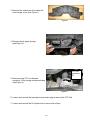
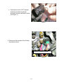
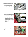
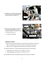
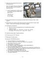
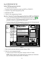
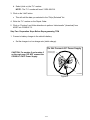
Classification:
Reference:
AT05-009a
Date:
NTB05-084a
November 20, 2006
MURANO; LACK OF POWER ON TAKE OFF WITH DTC
P0868 STORED IN THE TCM AND NO MIL ON
This bulletin has been amended. The Applied Vehicles have been updated.
Please discard all previous copies of this bulletin.
APPLIED VEHICLES:
2003 - 2007 Murano (Z50)
IF YOU CONFIRM
A lack of power when accelerating from a standing start.
With
DTC P0868 stored in the TCM but no MIL ON.
ACTIONS
Step A: Remove the original valve body and install the parts listed in the Parts Information
section of this bulletin.
IMPORTANT: Make sure to erase the EEPROM (see step 28, page 9).
Step B: Reprogram the TCM (see page 10).
PRECAUTIONS WHEN REPLACING CVT VALVE BODY ASSEMBLY
1. If other DTCs are combined w/ P0868, resolve them first. Refer to ASIST and the
Service Manual for diagnostic information.
2. If you observe excessive contamination in the oil pan and/or can isolate an unusual
noise coming from the transmission, this TSB does not apply. Refer to the Service
Manual for further assistance.
3. Transmissions are very vulnerable to particles (dust, metal, etc.).
• When replacing a CVT valve body, make sure your work environment (shop,
workbench, etc.) the transmission area (sub-frame, oil pan, harness connector,
etc.) and your hands are free of contamination.
• Make sure all parts are clean prior to installing on the vehicle.
• Unpack Service Parts just before installation.
IMPORTANT: The purpose of “ACTIONS” (above) is to give you a quick idea of the work you will
be performing. You MUST closely follow the entire Service Procedure (starting on page 2) as it
contains information that is essential to successfully completing this repair.
Nissan Bulletins are intended for use by qualified technicians, not 'do-it-yourselfers'. Qualified technicians are
properly trained individuals who have the equipment, tools, safety instruction, and know-how to do a job
properly and safely. NOTE: If you believe that a described condition may apply to a particular vehicle, DO
NOT assume that it does. See your Nissan dealer to determine if this applies to your vehicle.
1/13
PARTS INFORMATION
DESCRIPTION
Valve body-Assembly
Gasket oil pan
Nissan CVT Fluid
Seal -lip
Bolt -hex
Bolt
Bolt-flange hex
Seal-O ring, drain plug (Aluminum
pan only)
Wash-drain plug (Steel pan only)
Bolt (Aluminum pan only)
Bolt (Steel pan only)
PART #
31705-1XD11
31397-1XD00
999MP-NS200P
31528-1XA01
01121-03071
31377-1XA04
081A0-6301A
31526-1XA01
QUANTITY
1
1
8 Qts.
2
5
2
4
1
11026-01M02
31377-1XD07
31377-1XD06
1
20
20
CLAIMS INFORMATION
Submit a Primary Failed Part (PP) line claim using the following claims coding:
DESCRIPTION
PFP OP CODE SYM
DIA
FRT
RPL Valve Body Assy
(1)
JX05AA
ZE
32
1.4 hrs
Reprogram TCM
JE99AA
(2)
1. Reference the Parts Information Table and use the applicable Valve Body Assy P/N as
the PFP.
2. Reference the current Nissan Warranty Flat Rate Manual and use the indicated FRT.
SERVICE PROCEDURE
Step A: Remove and replace the valve body.
1. A. Write down all radio station presets.
Presets
A
B
C
1
2
3
4
5
B. Disconnect both battery cables (negative cable first).
C. Wait at least 3 minutes after the battery cables are disconnected.
2. Remove the CVT dipstick. Raise the vehicle on a hoist.
2/13
6
3. Remove the undercover from below the
front bumper cover (see Figure 1).
Figure 1
4. Remove the air guide (scoop)
(see Figure 2).
Figure 2
CVT unit
connector
F6
5. Disconnect the CVT unit harness
connector F6 by turning counterclockwise
(see Figure 3).
Figure 3
6. Loosen and remove the transmission pan drain plug to remove the CVT fluid.
7. Loosen and remove the 20 oil pan bolts to remove the oil pan.
3/13
Manual
Plate
8. Remove the nut and lock nut to remove
the manual plate.
Nut
Lock nut
Figure 4
Collar
9. Remove the collar from the manual shaft.
Figure 5
CVT
Connector
10. Remove the large lock ring holding the
CVT connector to the transmission case
(see Figure 6).
• Push the transmission side of the
harness down inside the transmission
case to remove it.
Lock ring
Figure 6
4/13
• Transmission side of CVT harness
connector and lock ring shown
removed from the transmission case
(see Figure 7).
Figure 7
11. Disconnect the harness of the Primary
oil pressure sensor.
Primary oil pressure sensor
Figure 8
5/13
12. Remove the bolts attaching the valve body to the transmission (see Figure 9).
•
There are 11 bolts shown and numbered for convenience.
•
There are 3 different length bolts which are identified by:
S-short
M-medium
L-long
3S
8L
9S
7L
6L
4L
5L
2M
10S
1M
11S
Figure 9
Shift link
13. Remove the valve body. Note the
position of the Ratio Control Valve and
attached shift link.
Ratio Control Valve
Figure 10
6/13
14. Make sure you replace the 2 lip seals
shown in Figure 11.
•
Do not reuse the old lip seals.
•
Use petroleum jelly to keep the new
lip seals in place during reassembly.
.
Lip seals
Figure 11
15. Carefully unpack the new valve body
assembly. When installing the new valve
body, be careful not to allow the Ratio
Control Valve to fall out (see Figure 10).
•
If the Ratio Control Valve does fall
out, check the condition of all surfaces
especially the edges for damage.
Shift link.
Notice the direction
Step motor pin
• Confirm (double check) the direction
of the shift link and the bottom of the
shift link around the step motor pin
(see Figure 12).
Figure 12
16. Route the harness around the outside of
the Valve body as shown (see Figure
13).
Figure 13
7/13
Pin
17. Install the new valve body and shift link
with the fork end of the shift link around
the pin as shown (see Figure 14).
Shift link
Figure 14
Shift link
18. While you are doing Step 17 above, the
lower end of the shift link must stick
through the bottom of the step motor pin
as shown (see Figure 15).
•
Install the CVT dipstick.
Step motor pin
Figure 15
IMPORTANT CHECKS:
• Make sure the upper end (forked end) of the shift link is positioned around the pin
after you install the new valve body. Space is very limited in the work area.
•
Make sure there is adequate clearance between the dipstick and harness.
19. Install and torque the 11 valve body bolts removed in Step 12 (see Figure 9).
•
Tightening torque: 6.9-8.9 N m (0.7-0.9 kg-m, 61-78 in-lb).
•
Torque sequence as per Figure 9: 6-7-5-8-4-9-3-10-2-11-1.
20. Re-install the collar on the manual shaft removed in Step 9 (see Figure 5).
8/13
21. Align the manual plate with the notch in
the manual valve.
Note: First, tighten 19 mm nut, then tighten
the 14 mm lock nut with the specified
tightening torque.
Manual
plate
Manual
valve
• Use a Torque wrench to tighten both the
14 mm and 19 mm nuts; same torque
spec for both :
20.6-23.5 N m
(2.1-2.3 kg-m,
15.1-17.3 ft-lb)
Figure 16
22. Reconnect the harness to the primary oil pressure sensor as shown in Step 11 and
Figure 8.
23. Reinsert the CVT connector with locking ring into the case as shown in Figure 6 and
Figure 7. Check that the locating notch is properly engaged.
24. Install the oil pan and bolts.
• Make sure oil pan and magnets are free of contamination particles.
•
Tightening Torque:
Aluminum oil pan - 5.4 - 7.4 N m (0.5 - 0.7 kg-m, 3.9 - 5.4 lb-ft).
Iron oil pan - 6.9 -10.8 N m ( 0.7-1.1 kg-m, 5.0 - 7.9 lb-ft).
25. Install the battery cables. Negative cable last.
26. Fill and check the CVT fluid level.
27.Reprogram the radio presets.
28. Erase the TCM EEPROM memory.
a.
b.
c.
d.
e.
f.
g.
Connect CONSULT-II to data link connector.
Turn ignition switch ON. Confirm that CONSULT-II is turned ON.
Move selector lever to “R” position.
Touch START on CONSULT-II.
On CONSULT-II select TRANSMISSION > SELF-DIAG RESULTS.
Press on the Brake (Brake switch ON).
Press the accelerator pedal (0.5/8 – 4/8 throttle) not to exceed half, and hold it in the
half or less open position. (This will set the closed throttle position signal to OFF and
the wide open throttle position signal to OFF.)
h. On CONSULT-II touch ERASE, then touch YES.
i. Wait 3 seconds and then release the accelerator pedal.
j. Turn ignition switch OFF.
9/13
Step B: REPROGRAM THE TCM
Vehicle TCM Reprogramming Overview
•
There are four basic steps:
1. Download (transfer) reprogramming data from ASIST into CONSULT-II.
2. “Preparation” steps before reprogramming TCM.
3. Reprogram the TCM.
4. “Wrap-up” after reprogramming is finished.
Step One: Download (Transfer) Reprogramming Data From ASIST Into CONSULT-II
•
If you’re not familiar with the latest TCM reprogramming procedures, click here.
This will link you to the "TCM Reprogramming For Nissan Vehicles" general
procedure, or refer to it in the print copy of this bulletin.
•
For those familiar with TCM Reprogramming, please review the following steps and
use them as a Quick Reference for TCM reprogramming.
Vehicle /
Model
Configuration
* Click the "Add" button
350Z
2004
1 File(s) selected
Vehicle Configuration #1
Maxima
2003
Altima
2002
TCM
Sentra
2001
TCM
TCM
Used
Space
16MB
To 31036-XXXXX Engine #1, Trans #1, etc
To 31036-XXXXX Engine #1, Trans #1, etc.
TCM
To: 31036-XXXXX
Vehicle Configuration #2
"To"
Number
TCM
Quest
2000
Vehicle Configuration #3
TCM
Pathfinder
To 31036-XXXXX Engine #1, Trans #1, etc.
To 31036-XXXXX Engine #1, Trans #1, etc.
To 31036-XXXXX Engine #1, Trans #1, etc.
Murano
Details:
Xterra
Add
Replaces 31036-XXXXX, -XXXXX
Frontier
8MB
Remove
More
More
Search by Code
(per bulletin only)
KeyPad
Back
Up
Show me
Main
Menu
Continue
This illustration is for example only, your vehicle may be different.
TP030621h
Figure A
1. Select vehicle model and model year (example: Murano, 2004).
2. Select the correct reprogramming data:
a. Locate the specific “Model Configuration” (Example: VQ35, CVT, 2WD).
NOTE: Model Configuration may include items such as engine type, transmission
type, and vehicle options such as ASCD, TCS, ABS etc.
10/13
b. Select (click on) the “To” number.
NOTE: The “To” number will read: 31036-XXXXX.
3. Click on the “Add” button.
•
This will add the data you selected to the “File(s) Selected” list.
4. Write the “To” number on the Repair Order.
5. Click on “Continue” and follow directions to perform “data transfer” (download) from
ASIST into CONSULT-II.
Step Two: Preparation Steps Before Reprogramming TCM
1. Connect a battery charger to the vehicle's battery.
•
Set the charger to a low charge rate (trickle charge).
Do Not Connect A/C Power Supply
CAUTION: For number 2 and number 3
on the next page, DO NOT connect the
CONSULT-II A/C Power Supply.
Consult-II A/C
Power Supply
TP040090
Figure B
11/13
NISSAN
ELECTRONIC CONTROL UNIT
REPROGRAMMING
2. Press SUB MODE (see Figure C) then:
AER02C-1
a. From the listed items, find and
select BATTERY CHARGE.
INITIATE ECU REPROGRAM
SUB MODE
LIGHT
COPY
TP030620
Figure C
Battery Charging
CONSULT-II
Battery
Voltage
3. Check the CONSULT-II’s “Charger
Input” reading (see Figure D).
Elapsed
Discharge
Charge Time
00:01.02
00.00:00
00:01.02
Battery Voltage
Charger Input
8.32 12.15
0%
NOTE:
0
•
“Battery Voltage” is the voltage level
of CONSULT-II's battery.
•
MUST BE
ABOVE
12.00 VOLTS!
100%
10
20 30
40 50
60 70
80 90 100
Battery Charge - IDLE
Start
Charging
"Charger Input" is the voltage level of
the vehicle’s battery. (It must be above
12 volts.)
Vehicle
Battery
Voltage
MODE
Check Charger
Input without
AC power
supply
connected.
Discharge &
Charge
BACK
LIGHT
COPY
TP030625
Figure D
CAUTION: If the “Charger Input” is below 12 volts:
•
A list of items to check when “Charger Input” voltage is below 12V is contained in
the "TCM Reprogramming For Nissan Vehicles" general procedure. Click here to
link to it.
Step Three: Reprogram the TCM
•
If you are not familiar with TCM Reprogramming, click here:
•
This will link you back to a general procedure called "TCM Reprogramming For Nissan
Vehicles."
12/13
Step Four: TCM Reprogramming “Wrap-up”
1. Turn the ignition and CONSULT-II OFF.
2. Disconnect CONSULT-II from the vehicle.
3. Start the Engine and make sure the MIL is OFF.
•
If it’s still ON, use CONSULT-II with the Diagnostic (red/white) Card to erase any
DTC’s that may have stored in the TCM and/or the ECM during the reprogramming
procedure.
4. Confirm there are no leaks from the transmission. Test-drive the vehicle and make sure
the transmission operates correctly in all modes and has a normal power level when
starting from a stop.
•
See the AT section of the appropriate Service Manual for operation specifications.
13/13