1
OSBORNE COMPUTER CORPORAnON
SCREEN-PAC OPTION
INST ALL AnON PROCEDURE
FOR THE OCC lilA COMPUTER
S8XNES021
Prepared by:
XEROX Corporation
XEROX Service Business
Service Education &: Customer Support
1341 W. Mockingbird Lane
Dallas, Texas 75247
OCTOBER 1983
dCC lilA
INTRODUCTION TO THE SCREEN-PAC OPTION
PURPOSE:
The purpose of this document is to provide you with the procedures
necessary to upgrade the OSBORNE COMPUTER CORPORATION
(aCC) lIlA COMPUTER to the 52-80-100-column screen option.
REQUIRED TOOLS:
Tool kit
WORDSTAR DISKETTE
W' Drill Bit (XEROX part no. 600T980)
318 " Drill (XEROX part no. 600T871)
Micro Soldering Tip (XEROX part no. 600TI039)
Soldering Heat Element (23-27 watt XEROX part no. 600TI036)
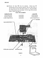
COMPONENTS IN THE SCREEN-PAC OPTION INCLUDE:
I SCREEN-PAC PWB With (2) Pin Spacers (OCC part no. 6NOOOOI-01)
1 SCREEN-PAC Ribbon Cable and Clips (OCC part no. 5N00002-0 1)
I 2732 Rev. 1.44 Monitor ROM (OCC part no. 3AI0082-00)
1 SCREEN-PAC Power Harness (OCC part no. 5N00005-0 1)
1 RCA External Video Connector and Cable OCC part no. 5N00006-0 1)
1 Template (OCC part no. 3N00009-0I)
2 PWB Retainer Clips (OCC part no. JN00008-0 1)
I SCREEN-PAC Users Guide and Extended Utility Disk
NOTE:
The Logic PWB in the computer must be revision G or higher for installation
of the Screen-Pac Option. Return earlier revision PWBs to OCC for upgrading
until further notice.
OCC lIlA & SCREEN-PAC are registered trademarks of the OSBORNE COMPUTER
Corp. WORDSTAR is a registered trademark of DIGITAL RESEARCH Inc.
I
OCC lilA
SCREEN-PAC OPTION INSTALLATION PROCEDURE
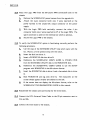
If the computer is receiving both the Double Density &: the SCREEN-PAC
options, complete the Double Density upgrade first.
1.0
Before starting the installation of the option, inspect the computer being
upgraded as follows.
A.
Check the case, handle, and AC power panel for damage.
B.
Check that all keys are in place on the keyboard.
C.
Detach the keyboard from the unit. Check the keyboard cable and
connector for damage.
D.
Check the keyboard connector on the front bezel for bent or
broken pins.
E.
Check the video monitor and contrast/brightness knobs for damage.
2.0
After completing the visual inspection, turn the computer on.
3.0
Verify computer operation in all modes of operation.
A.
Load the OSBORNE Disk Exerciser program and select the SEEK
TRACK function. Step to track 16.
B.
Select the DRIVE TIMER function. The reading should be 200
~"1 %.
Clean the head, replace the load pad, and adjust R23 on the drive
PWB if the reading are not wi thin specification. Inf orm the
customer of any problems encountered up to this point.
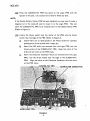
4.0
Using the Osborne Field Service Manual as reference, remove the Logic
PWB from the computer.
A.
Check the IC at location B13 on the Logic PWB. If it is a Fairchild
or SG (SILICON GENERAL) the PWB must be replaced. Return the
incorrect PWB to OCC for upgrade or credit.
B.
Examine the CRT Assembly. It should contain (1) Video PWB. If it
contains (2) PWBs the CRT assembly must be replaced. Return the
Video Assembly to OCC for upgrade or credit.
C.
Place the Logic PWB flat on a soft work surface, component side
up and the video shafts closest to you.
2
acc
lilA
.5.0
Examine the MONITOR ROM at location D12 of the Logic PWB. If it is
not revision 1.43 or higher, replace it with the 1.44 ROM which is part of
the kit. The notch on the ROM aligns with the notch on the Logic PWB
trace.
6.0
There must be a jumper at jumper position J3. Install one if necessary.
7.0
Remove the Z-80 Microprocessor from the Logic PWB. It is located in
Row C between columns 11 and 14.
8.0
Remove the Character Generator from the Logic PWB. It is located in
Row A between columns 15 and 17.
9.0
Examine the sockets on the Logic PWB where you removed the Z-80 and
Character Generator.
If you see the manufacturer's name, AMP, on
either socket, DO NOT proceed with the installation.
The pins on the
underside of the 80-column PWB do not fit AMP sockets correctly. If
the Logic PWB has AMP sockets, replace it with a PWB without AMP
sockets before continuing. Return the PWB with AMP sockets to OCC
for credit or upgrade.
10.0 Remove the SCREEN-PAC ribbon cable from the upgrade kit. The cable
has a 14-pin connector on one end, 12 long wires and 2 shorter wires on
the other end (the 2 shorter wires, red and yellow, will not be
connected).
A.
Attach a piece of double back foam tape (OCC part no.7P70032-00)
to the Logic PWB approximately
~
inch in from the edge of the
PWB, centered between the Keyboard Connector and the video
controls.
B.
With the ribbon cable connector towards you and the pins facing
up, press the cable to the tape approximately
~
inch before the
wires seperate. Approximately (2) to (3) inches of the ribbon cable
should be hanging off of the end of the Logic PWB.
C.
Using the low wattage heat element and the micro soldering tip,
connect the leads to the Logic PWB in the order listed in TABLE 1.
3
OCC lIlA
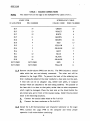
TABLE 1 SOLDER CONNECTIONS
The yellow wire on the edge of the SCREEN-PAC cable is wire 1.
NOTE:
LOGIC PWB
SCREEN-PAC CABLE
IC LOCATION
PIN NUMBER
COLOR CODE
WIRE NUMBER
017
14
GREEN
10
017
13
VIOLET
8
017
12
WHITE
6
017
11
BROWN
4
016
BROWN
14
016
5
4
RED
13
E13
1
YELLOW
1
014
5
ORANGE
12
B16
1
GREY
7
Bl1
12
BLUE
9
E22
12
BLACK
5
018
14
ORANGE
2
NOT USED
NOT USED
RED
3
NOT USED
NOT USED
YELLOW
11
11.0 Remove the 80-column PWB from the kit. The PWB includes a coaxial
cable which has one end already connected.
soldered to the Logic PWB.
The other end will be
To prevent the heat of the soldering iron
from melting the shield of the inner conductor a heat sink must be used.
A heat sink can be an alligator clip, needle nose pliers, or surgical
forceps which are attached to the item being soldered. The purpose of
the heat sink is to draw to that point, rather than to other components
which might be damaged. Place the heat sink on the shield behind the
pre-tinned area and in front of the coaxial casing. Solder the pre-tinned
leads to the following locations.
A.
Connect the coaxial cable shield to Pin 7 of B13.
B.
Connect the inner conductor to Pin 6 of B13.
12.0 Install the Z-80 Microprocessor and Character Generator on the Logic
PWB. Connect the Logic PWB to the computer and verify proper
operation in all modes before continuing •.
4
oce lilA
Remove the 2-80
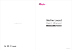
13.0 Remove the Logic PWB from the computer.
Microprocessor and the Character Generator. Place the Logic PWB on a
soft work surface with the video shafts towards you. Hold the SCREENPAC PWB component side up and align it with the Logic PWB as follows
(Refer to Table 2 and Figure 1).
TABLE 2 PIN ALIGNMENT
LOGIC PWB
SCREEN-PAC PWB
2-80 Microprocessor
ALIGN WITH
40-PIN SOCKET
Character Generator
ALIGN WITH
24-PIN SOCKET
IO-PIN CONNECTOR PI
ALIGN WITH
10-PIN CONNECTOR P9
, - - - SPACERS
MAIN LOGIC BOARD -
.......
. .....:.. -::.~'., .:' :, ", " ':":':~':\:':",,;,::,~' .->:' ",' : ",: ' :" .' ,,":":" " ::,:, "
: :....... :' : '.
'.
:.....
:"
.
:
:'
,,'.
. . ': .' . .' .~'.~ ..:.~ .:". :,::,,: ::." :.~
. .:-,' ...... :.":'
,,'
, , ,'. :'" .:::, ">;':
.... :
.
. :.~.:. .
..
',:\
.
...
"
'
,:'"
,,, .""
,','.,'
..
.:
'.
,
'
,
.:
"
......
'::
'
.
,
'••• :' 0':
.
,"
. ..
'"
.'" .... .... ...
~
~.:
:
'::":.....: " ,";' . .- :',
'
'
. ,,;:.:
:' "'::"
....
:
. .
"
'
'...
.......:...
''': ..
:
.:,":
. ',~':~
:....
,,-:
":':"::
••
'
':J
,: ·.··:·i
":::":.:":;
.'
.
.
".
.
.:.
...
,
.' .
,
....
.. .
.
,,'.
",
"
..
.
"
::' ..~.,
':' :
,KEYBOARD CONNECTOR
RETAINER CLIPS
FIGURE I
j
oce IlIA
14.0 Press the SCREEN-PAC PWB into place on the Logic PWB with the
spacers on the pins. Use caution not to bend or break any pins.
NOTE:
If the Double Density Option PWB has been installed, you may need to make a
diagonal cut in the stand-off used to mount it to the Logic PWB.
This will
allow the SCREEN-PAC PWB to be mounted next to the Double Density PWB
(Refer to Figure
O.
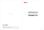
15.0 Locate the 40-pin socket near the center of the PWB, and the 24-pin
socket near the edge of the PWB (Refer to Figure 2).
A.
Check there are no obstructions in the 40-pin socket by carefully
probing each of the sockets with a sharp pin.
B.
Insert the Z-80 which you removed from the Logic PWB, into the
40-pin socket of the SCREEN-PAC PWB.
Align the notch of the
Z-80 with the notch on the PWB trace.
C.
Insert the Character Generator which you removed from the Logic
PWB, into the 24-pin socket near the edge of the SCREEN-PAC
PWB.
Align the notch on the Character Generator with the notch
on the PWB trace •
.seREEN-~Ae :.~~.~·:.::·.;::::::··.::·:\i::~. .:.ieHARAeTER GENERATOR
::::;f.~:~·f(;:.~i,:::::;::;:~~:;.;:::<.,,::·::·g··.t::·::~:>::::-;::::::·::::.;.::l:~:>::.·;·:·
~}};'N~;D,~~U,}iT'r'
""::' """
.
': .
.... .
'
',:-.
~fJtfoGic PWBt~,;X0;~;f;~(};FJ~j:;i~";;'in ;;!{i:i¥5:'r::
FIGURE 2
6
......... -.
:',
:
OCC IlIA
16.0 Connect the ribbon cable from the Logic PWB to P3 on the 80-Column
PWB. Remove the (2) PWB Retainer Clips from the upgrade kit.
A.
Insert (1) retainer clip into the hole on the Logic PWB between the
ribbon cable and the keyboard connector.
Fasten the SCREEN-
PAC PWB to this clip (Refer to Figure 1.)
8.
Position the other retainer clip on the opposite edge of the
SCREEN-PAC PWB.
Fasten this clip into the hole between
locations A13 and A14 (Refer to Figure 1.)
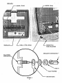
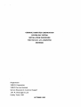
17.0 Remove the RCA External Video Cable and template from the kit. The
Video Cable includes a ground ring, washer, and 7/16 inch nut to secure
it to the bezel (Refer to Figure 3). The cable requires a u,. inch hole
through the front bezel next to the battery cutout. The template will be
used to position this hole correctly.
A.
Press the template into position against the front surface of the
bezel. Align the cutout on the tern plate with the Battery cutout on
the bezel (Refer to Figure 3.)
8.
Using the 3/8 " drill and W' drill bit, drill a hole through the front
of the bezel at the point marked on the template.
Remove the
template.
C.
Remove the single pin connector from the video connector pin.
Remove the 7/16 inch nut, flat washer, and ground ring from the
video connector pin.
D.
Insert the video connector from the outside of the bezel through
the M. inch hole.
E.
Install the ground ring, flat washer, and the 7/16 inch nut on the
video connector shaft.
Carefully tighten the nut until the
connector is secure.
F.
Plug the single pin connector into the video connector pin.
7
oce
lIlA
...-- BEZEL (Front)
,
-:.:.--; .
.'.
.::.'
..::!....
:
.. ::.:: ..... ..... : ....
"
II
DRILL 1/4 DIA HOLE
SCREEN PAC
VIDEO HARNESS
SINGLE PIN CONNECTOR ...;..
RCA VIDEO
CONNECTOR
FLAT WASHER
' - - GROUND RING
FIGURE 3
8
OCC lIlA
18.0 Place the Logic PWB (with the 80-column PWB connected) close to the
chassis.
A.
Remove the SCREEN-PAC power harness from the upgrade kit.
8.
Attach the 4-pin connector (with only 3 wires inserted) on the
power harness to the unused DC output connector on the power
supply.
C.
With the Logic PWB held vertically, connect the other 4 pin
connector (with only 2 wires inserted) to P7 of the Logic PWB. The
spare connector is used for the external fan which is optional.
D.
Secure the Logic PWB to the chassis.
19.0 To verify the SCREEN-PAC option is functioning correctly perform the
following procedure.
A.
Use the copy of the EXTENDED UTILITY disk which came with the
kit. Place a a write protect strip over the notch.
8.
Insert the disk into drive A.
C.
Insert a WORDST AR disk into drive B.
D.
Reference the SCREEN-PAC USER'S GUIDE to SYSGEN CP/M
from the EXTENDED UTILITY disk to the WORDST AR disk.
E.
Reference the SCREEN-PAC USER'S GUIDE to use the SETUP
program with WORDST AR in the 80-column format.
F.
Insert the WORDSTAR disk in drive A and a formatted disk in drive
B.
G.
~Boot
WORDS TAR and log onto drive B.
The characters on the
screen should appear smaller and shifted to the left.
H.
If the screen does not display the 80-column format, refer to the
SCREEN-PAC TROUBLESHOOTING GUIDE in this manual.
20.0 Reassemble the chassis and case except for the front bezel.
21.0 Connect the RCA External Video Cable to the (2) pin connector next to
C16 and 126.
22.0 Connect the front bezel to the chassis.
9
oce
lIlA
NOTE:
Osborne 12 inch video monitors need an adapter. cable for connection to the
RCA External Video Connector. OCC will provide this adapter to end users
with these monitors.
10
acc lIlA
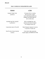
TABLE 3 SCREEN-PAC TROUBLESHOOTING GUIDE
PROBLEM
ACTION
Computer "beeps" when
Turn power off for 5 seconds.
powered-on
Then turn power on again.
Check 2-80 Microprocessor ,2-80
connector, and 40-pin socket for
bent or broken pins.
Scrambled logo when computer
Refer to SCREEN-PAC users
is powered-on
Guide and check SETUP program
for 128 logical screen size.
Lines across screen in 52 and 80
Check Character Generator for secure
fi t and bent or broken pins
Only 52 column format functions
Check power cable connections
correctly
to power supply and SCREEN-PAC PWB.
11
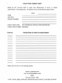
PUBLICATION COMMENT SHEET
Please use this comment sheet to assist with identification of errors or needed
improvements in this publication. For specific errors, include specific page numbers.
DATE
NAME
JOB TITLE
MAILING ADDRESS
PUBLICATION NAME
OCC SCREEN-PAC INSTALLATION PROCEDURE
PUBLICATION NUMBER SBXNES021
PAGE NO.
DESCRIPTION OF ERROR OR IMPROVEMENT
Please mail this form to the following address.
XEROX CORPORATION
1341 W. MOCKINGBIRD LANE
MS301
DALLAS, TEXAS 75247
ATTN: DAVID LEESE, MANAGER XSB SERVICE EDUCATION & CUSTOMER SUPPORT