1
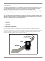
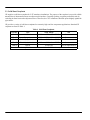
GE Measurement & Control Model C-ET Ultrasonic Flow Transducer System Installation Guide 916-083 Rev. A February 2012 Model C-ET Ultrasonic Flow Transducer System Installation Guide 916-083 Rev. A February 2012 www.ge-mcs.com ©2012 General Electric Company. All rights reserved. Technical content subject to change without notice. [no content intended for this page] ii Preface Information Paragraphs • Note paragraphs provide information that provides a deeper understanding of the situation, but is not essential to the proper completion of the instructions. • Important paragraphs provide information that emphasizes instructions that are essential to proper setup of the equipment. Failure to follow these instructions carefully may cause unreliable performance. • Caution! paragraphs provide information that alerts the operator to a hazardous situation that can cause damage to property or equipment. • Warning! paragraphs provide information that alerts the operator to a hazardous situation that can cause injury to personnel. Cautionary information is also included, when applicable. Safety Issues WARNING! It is the responsibility of the user to make sure all local, county, state and national codes, regulations, rules and laws related to safety and safe operating conditions are met for each installation. Auxiliary Equipment Local Safety Standards The user must make sure that he operates all auxiliary equipment in accordance with local codes, standards, regulations, or laws applicable to safety. Working Area WARNING! Auxiliary equipment may have both manual and automatic modes of operation. As equipment can move suddenly and without warning, do not enter the work cell of this equipment during automatic operation, and do not enter the work envelope of this equipment during manual operation. If you do, serious injury can result. WARNING! Make sure that power to the auxiliary equipment is turned OFF and locked out before you perform maintenance procedures on the equipment. Qualification of Personnel Make sure that all personnel have manufacturer-approved training applicable to the auxiliary equipment. Personal Safety Equipment Make sure that operators and maintenance personnel have all safety equipment applicable to the auxiliary equipment. Examples include safety glasses, protective headgear, safety shoes, etc. Unauthorized Operation Make sure that unauthorized personnel cannot gain access to the operation of the equipment. C-ET Ultrasonic Flow Transducer System Installation Guide iii Preface Environmental Compliance Waste Electrical and Electronic Equipment (WEEE) Directive GE Measurement & Control is an active participant in Europe’s Waste Electrical and Electronic Equipment (WEEE) take-back initiative, directive 2002/96/EC. The equipment that you bought has required the extraction and use of natural resources for its production. It may contain hazardous substances that could impact health and the environment. In order to avoid the dissemination of those substances in our environment and to diminish the pressure on the natural resources, we encourage you to use the appropriate take-back systems. Those systems will reuse or recycle most of the materials of your end life equipment in a sound way. The crossed-out wheeled bin symbol invites you to use those systems. If you need more information on the collection, reuse and recycling systems, please contact your local or regional waste administration. Visit http://www.ge-mcs.com/en/about-us/environmental-health-and-safety/1741-weee-req.html for take-back instructions and more information about this initiative. iv C-ET Ultrasonic Flow Transducer System Installation Guide Contents 1. 2. 3. Introduction . . . . . . . . . . . . . . . . . . . . . . . . . . . . . . . . . . . . . . . . . . . . . . . . . . . . . . . . . . . . . . . . . . . . . . . . . . . . . . . . . . . . . . . . . . . . 1 Transducer Construction. . . . . . . . . . . . . . . . . . . . . . . . . . . . . . . . . . . . . . . . . . . . . . . . . . . . . . . . . . . . . . . . . . . . . . . . . . . . . . . . 1 2.1 Solid Sheet Couplants . . . . . . . . . . . . . . . . . . . . . . . . . . . . . . . . . . . . . . . . . . . . . . . . . . . . . . . . . . . . . . . . . . . . . . . . . . . . . . . 2 Installing the C-ET Transducer System. . . . . . . . . . . . . . . . . . . . . . . . . . . . . . . . . . . . . . . . . . . . . . . . . . . . . . . . . . . . . . . . . . . 3 3.1 Choosing an Installation Location. . . . . . . . . . . . . . . . . . . . . . . . . . . . . . . . . . . . . . . . . . . . . . . . . . . . . . . . . . . . . . . . . . . . 4 3.1a Application Guide - Wall Thickness (in inches) . . . . . . . . . . . . . . . . . . . . . . . . . . . . . . . . . . . . . . . . . . . . . . . . . . 5 3.1b Application Guide - Wall Thickness (in millimeters). . . . . . . . . . . . . . . . . . . . . . . . . . . . . . . . . . . . . . . . . . . . . . 6 3.2 Obtaining the Transducer Spacing . . . . . . . . . . . . . . . . . . . . . . . . . . . . . . . . . . . . . . . . . . . . . . . . . . . . . . . . . . . . . . . . . . . 7 3.2a Determining Special Transducer Parameters . . . . . . . . . . . . . . . . . . . . . . . . . . . . . . . . . . . . . . . . . . . . . . . . . . 7 3.2b Pipe Survey to Determine OD and Wall Thickness . . . . . . . . . . . . . . . . . . . . . . . . . . . . . . . . . . . . . . . . . . . . .11 3.2c Fluid Soundspeed . . . . . . . . . . . . . . . . . . . . . . . . . . . . . . . . . . . . . . . . . . . . . . . . . . . . . . . . . . . . . . . . . . . . . . . . . . .12 3.3 Installing the V Clamping Fixtures and Transducers. . . . . . . . . . . . . . . . . . . . . . . . . . . . . . . . . . . . . . . . . . . . . . . . . .12 3.3a Tools and Equipment Needed . . . . . . . . . . . . . . . . . . . . . . . . . . . . . . . . . . . . . . . . . . . . . . . . . . . . . . . . . . . . . . . .12 3.3b Setting the Transducer Spacing . . . . . . . . . . . . . . . . . . . . . . . . . . . . . . . . . . . . . . . . . . . . . . . . . . . . . . . . . . . . . .13 3.3c Installing the Fixture . . . . . . . . . . . . . . . . . . . . . . . . . . . . . . . . . . . . . . . . . . . . . . . . . . . . . . . . . . . . . . . . . . . . . . . . .15 3.3d Preparing the Pipe. . . . . . . . . . . . . . . . . . . . . . . . . . . . . . . . . . . . . . . . . . . . . . . . . . . . . . . . . . . . . . . . . . . . . . . . . . .18 3.3e Mounting the Transducers . . . . . . . . . . . . . . . . . . . . . . . . . . . . . . . . . . . . . . . . . . . . . . . . . . . . . . . . . . . . . . . . . . .20 3.4 Installing the PI Fixture and Transducers . . . . . . . . . . . . . . . . . . . . . . . . . . . . . . . . . . . . . . . . . . . . . . . . . . . . . . . . . . . .23 3.4a Tools and Equipment Needed . . . . . . . . . . . . . . . . . . . . . . . . . . . . . . . . . . . . . . . . . . . . . . . . . . . . . . . . . . . . . . . .23 3.4b Preparing the Pipe. . . . . . . . . . . . . . . . . . . . . . . . . . . . . . . . . . . . . . . . . . . . . . . . . . . . . . . . . . . . . . . . . . . . . . . . . . .24 3.4c Surveying the Pipe. . . . . . . . . . . . . . . . . . . . . . . . . . . . . . . . . . . . . . . . . . . . . . . . . . . . . . . . . . . . . . . . . . . . . . . . . . .24 3.4d Installing the First Mounting Block. . . . . . . . . . . . . . . . . . . . . . . . . . . . . . . . . . . . . . . . . . . . . . . . . . . . . . . . . . . .27 3.4e Installing the Second Mounting Block. . . . . . . . . . . . . . . . . . . . . . . . . . . . . . . . . . . . . . . . . . . . . . . . . . . . . . . . .29 3.4f Mounting the Transducers. . . . . . . . . . . . . . . . . . . . . . . . . . . . . . . . . . . . . . . . . . . . . . . . . . . . . . . . . . . . . . . . . . . .32 4. 5. Maintenance . . . . . . . . . . . . . . . . . . . . . . . . . . . . . . . . . . . . . . . . . . . . . . . . . . . . . . . . . . . . . . . . . . . . . . . . . . . . . . . . . . . . . . . . . .35 Specifications . . . . . . . . . . . . . . . . . . . . . . . . . . . . . . . . . . . . . . . . . . . . . . . . . . . . . . . . . . . . . . . . . . . . . . . . . . . . . . . . . . . . . . . . .36 CET Ultrasonic Flow Transducer System Installation Guide v Contents [no content intended for this page] vi CET Ultrasonic Flow Transducer System Installation Guide 1. Introduction The clamp-on extended temperature (C-ET) range transducer system provides liquid flow measurement in very low- or very high-temperature applications. It represents GE’s latest generation of non-contact, demanding measurement transducers and capitalizes on more than 20 years of experience from the OKS transducer system. The C-ET system is designed to isolate the transducer from the extreme process conditions, enabling it to measure high temperature hydrocarbon liquids, superheated water, heat transfer oils and cryogenic liquids. In addition, the C-ET system retains all of the characteristics that make ultrasonic technology best for critical process measurements under harsh conditions. The C-ET clamp-on ultrasonic flow transducers are used exclusively with the GE line of ultrasonic flowmeters. These transducers are used to measure the flow of various liquids through pipes having diameters from 3 in. (75 mm) to 24 in. (600 mm). This document provides details on the following topics: • Transducer Construction • Installation • Maintenance • Specifications 2. Transducer Construction The C-ET transducer consists of a C-RS transducer, a waveguide, and a holder pre-assembled from the factory. The transducer assembly includes a 316 stainless steel housing with a plastic wedge attached and a BNC-type electrical connector. The transducer features integral 3/4” NPT-M threads for mounting a junction box and integral 5/8-24 threads for mounting a submersible connector if desired (see Figure 1). BNC Connector 5/8” UNF Thread 3/4” NPT Thread Holder Waveguide Figure 1: Transducer Assembly C-ET Ultrasonic Flow Transducer System Installation Guide 1 2.1 Solid Sheet Couplants GE supplies a solid sheet couplant for C-ET transducer installations. The purpose of the couplant is to provide reliable transmission of ultrasound between two adjacent solid surfaces. Generally speaking, couplants perform this task by excluding air from between the adjacent surfaces. Therefore, the C-ET transducers should be pressed tightly against the pipe surface. GE provides a variety of solid sheet couplants for extremely high- and low-temperature applications. Standard GE couplants are listed in Table 1. Table 1: Solid Sheet Couplants Temp. Range Part No. Type Use CPL-12 Standard –20° to +400°C (-4° to +752°F) Permanent CPL-13 Cryogenics –250° to 100°C (-418° to +212°F) Permanent CPL-14 Gold Only Applications –20° to +400°C (-4° to +752°F) Permanent CPL-15 Zinc Only Applications –20° to +400°C (-4° to +752°F) Permanent CPL-S Special As required Difficult Applications* *Installations where gold or zinc cannot be used. Consult GE for these applications. 2 C-ET Ultrasonic Flow Transducer System Installation Guide 3. Installing the C-ET Transducer System GE offers the following fixtures to suit your applications needs: • V clamping fixture • PI clamping fixture Figure 2 shows the V and PI fixture assemblies (less solid couplant). Complete the steps in the following sections to position and install the transducers and fixtures. V Fixture PI Fixture Figure 2: V and PI Fixtures C-ET Ultrasonic Flow Transducer System Installation Guide 3 3.1 Choosing an Installation Location 1. Locate the transducer measurement point at least 3 ft (1 m) from any butt welds or flanges, ideally in the center of a 20 diameters of straight run of pipe. Keep appropriate clearance on either side of the pipe for easy transducer installation: • 6 in. (15 cm) if you are not using a junction box, or • 9 in. (23 cm) if you are using a junction box. Note: To guarantee the specified accuracy of the flowmeter there is no substitute for straight run and fully-developed flow profile. However, if straight run is not available, the transducer location should be in a position such that the acoustic signal travels through the full distribution of the under-developed flow profile for best repeatability. 2. Choose a location that has at least 10 pipe diameters of straight, undisturbed flow upstream and 5 pipe diameters downstream from the measurement point. Providing undisturbed flow means avoiding sources of turbulence such as flanges, elbows and tees; avoiding swirl; and avoiding disturbed flow profiles. Never install the flowmeter directly downstream of control valves, especially butterfly valves. If you cannot find an ideal location, use a downstream location of straight run in excess of 5 pipe diameters. 3. Place the transducers as close as possible to the horizontal plane. Locate the transducers on opposite sides of the pipe 180o apart, ideally at the 3 and 9 o’clock positions. Do not place transducers on the top or bottom of the pipe. Pipe Transducer Signal Path End View Figure 3: Transducer Locations 4. The following is a guide for the recommended wall thickness in which to install the C-ET transducers. The C-ET transducer cannot be installed on wall thicknesses between 0.27 in (6.86 mm) and 0.33 in (8.38 mm). On page 5 and page 6 are two charts showing typical pipe sizes. 4 C-ET Ultrasonic Flow Transducer System Installation Guide 3.1a Application Guide - Wall Thickness (in inches) Nominal Outside Pipe Size Diameter (in) (in) Schedule 10 20 30 STD 40 60 XS 80 100 120 140 160 XXS 0.438 0.600 0.531 0.674 Wall Thickness (in) 3 3.500 0.216 0.216 0.300 0.300 3 1/2 4.000 0.226 0.226 0.318 0.318 4 4.500 0.237 0.237 0.337 0.337 5 5.563 0.258 0.258 0.375 0.375 0.500 0.625 0.75 6 6.625 0.280 0.280 0.432 0.432 0.562 0.719 0.864 8 8.625 0.250 0.277 0.322 0.322 0.406 0.500 0.500 0.594 0.719 0.812 0.906 0.875 10 10.750 0.250 0.307 0.365 0.365 0.500 0.500 0.594 0.719 0.844 1.000 1.125 1.000 12 12.750 0.250 0.330 0.375 0.406 0.562 0.500 0.688 0.844 1.000 1.125 1.312 1.000 14 14.000 0.250 0.312 0.375 0.375 0.438 0.594 0.500 0.750 0.938 1.094 1.25 1.406 16 16.000 0.250 0.312 0.375 0.375 0.500 0.656 0.500 0.844 1.031 1.219 1.438 1.594 18 18.000 0.250 0.312 0.438 0.375 0.562 0.750 0.500 0.938 1.156 1.375 1.562 1.781 20 20.000 0.250 0.375 0.500 0.375 0.594 0.812 0.500 0.938 1.156 1.375 1.562 1.781 22 22.000 0.250 0.375 0.500 0.375 0.875 0.500 1.125 1.375 1.625 1.875 2.125 24 24.000 0.250 0.375 0.562 0.375 0.989 0.500 1.219 1.531 1.812 2.062 2.344 0.688 0.438 Note: Pipe sizes not suitable for C-ET installations are highlighted in red. C-ET Ultrasonic Flow Transducer System Installation Guide 5 3.1b Application Guide - Wall Thickness (in millimeters) Nominal Outside Pipe Size Diameter (mm) (mm) 80 Schedule 10 20 30 STD 40 88.90 5.49 5.49 60 XS 80 100 120 140 Wall Thickness (mm) 7.62 7.62 160 XXS 11.13 15.24 90 101.60 5.74 5.74 8.08 8.08 100 114.30 6.02 6.02 8.56 8.56 11.13 13.49 17.12 125 141.30 6.55 6.55 9.53 9.53 12.70 15.88 19.05 150 168.28 7.11 7.11 200 219.08 6.35 7.04 8.18 8.18 250 273.05 6.35 7.80 9.27 300 323.85 6.35 8.38 9.53 350 355.60 6.35 7.92 9.53 9.53 11.13 400 406.40 6.35 7.92 9.53 9.53 12.70 16.66 12.70 21.44 26.19 30.96 36.53 40.49 450 457.20 6.35 7.92 11.13 9.53 14.27 19.05 12.70 23.83 29.36 34.93 39.67 45.24 500 508.00 6.35 9.53 12.70 9.53 15.09 20.62 12.70 23.83 29.36 34.93 39.67 45.24 550 558.80 6.35 9.53 12.70 9.53 22.23 12.70 28.58 34.93 41.28 47.63 53.98 600 609.60 6.35 9.53 14.27 9.53 25.12 12.70 30.96 38.89 46.02 52.37 59.54 10.97 10.97 18.26 21.95 10.31 12.70 12.70 15.09 18.26 20.62 23.01 22.23 9.27 12.70 12.70 15.09 18.26 21.44 25.40 28.58 25.40 10.31 14.27 12.70 17.48 21.44 25.40 28.58 33.32 25.40 15.09 12.70 19.05 23.83 27.79 31.75 35.71 17.48 14.27 Note: Pipe sizes not suitable for C-ET installations are highlighted in red. 6 C-ET Ultrasonic Flow Transducer System Installation Guide 3.2 Obtaining the Transducer Spacing 3.2a Determining Special Transducer Parameters The C-ET transducers must be programmed in the flowmeters as special transducers. As specials, four parameters are required: Frequency, Tw, Wedge Angle, and Wedge Soundspeed. Frequency: Frequency is determined based on the part number of the C-ET transducer, and it can be found on the C-ET label. Figure 4: C-ET Parameters Label The CRS-XX-MB defines the frequency of the transducers as follows: If “XX” = 05, then the frequency =.5MHz. If “XX” = 10, then the frequency = 1MHz. Tw: Tw (time in wedge) is determined by the transducer frequency, nominal process temperature, and ambient temperature using Graph #1 (Figure 5 on page 8) or Graph #2 (Figure 6 on page 9) based on the transducer frequency. As an example: If Transducer Frequency = 0.5MHz Ambient Temperature = 20°C Nominal Process Temperature = 340°C Tw would be: 150µs Wedge Angle: Wedge angle is determined by the nominal process temperature and ambient temperature using Graph #3 on page 10 similar to Tw above. As an example: If Ambient Temperature = 20°C Nominal Process Temperature = 340°C Wedge Angle would be: 57.2 degrees Wedge Soundspeed: Wedge soundspeed is always 10104.9 ft/s (3080.0 m/s) for the C-ET transducer. C-ET Ultrasonic Flow Transducer System Installation Guide 7 Figure 5: Graph #1: Tw (0.5 MHz Transducer) 8 C-ET Ultrasonic Flow Transducer System Installation Guide Tw (μs) 139 140 141 142 143 144 145 146 147 148 149 150 151 152 153 154 155 156 157 158 159 160 161 162 0 25 50 dĂŵď͗ϲϬȗ dĂŵď͗ϰϬȗ dĂŵď͗ϮϬȗ dĂŵď͗Ϭȗ 164 163 Tamb: -ϮϬȗ 165 166 75 100 125 175 200 225 250 Nominal Process Temperature (ȗͿ 150 275 300 325 350 375 400 Figure 6: Graph #2: Tw (1.0 MHZ Transducer) C-ET Ultrasonic Flow Transducer System Installation Guide 9 Tw (μs) 136 137 138 139 140 141 142 143 144 145 146 147 148 149 150 151 50 75 dĂŵď͗ϲϬȗ 153 25 dĂŵď͗ϰϬȗ 154 0 dĂŵď͗ϮϬȗ 155 152 dĂŵď͗Ϭȗ Tamb: -ϮϬȗ 156 157 158 100 125 175 200 225 250 EŽŵŝŶĂůWƌŽĐĞƐƐdĞŵƉĞƌĂƚƵƌĞ;ȗͿ 150 275 300 325 350 375 400 Figure 7: Graph #3: Wedge Angle 10 C-ET Ultrasonic Flow Transducer System Installation Guide Wedge Angle (Degrees) 53.50 54.00 54.50 55.00 55.50 56.00 56.50 57.00 57.50 58.00 58.50 59.00 59.50 60.00 60.50 0 25 50 75 dĂŵď͗ϲϬȗ dĂŵď͗ϰϬȗ dĂŵď͗ϮϬȗ dĂŵď͗Ϭȗ Tamb: -ϮϬȗ 100 125 175 200 225 250 EŽŵŝŶĂůWƌŽĐĞƐƐdĞŵƉĞƌĂƚƵƌĞ;ȗͿ 150 275 300 325 350 375 400 3.2b Pipe Survey to Determine OD and Wall Thickness Finding a location where the pipe is concentric is important for optimum accuracy and performance. If possible, perform a pipe survey with an ultrasonic thickness gauge to find the best location. Measure the outside diameter (OD) of the pipe using a tape measure or other suitable device. Mark a circumferential line with the tape measure. Note: If you are using a PT878 thickness gauge at extreme high or low temperatures, it can be in contact with the pipe for less than two seconds only and then must be removed. Allow it to cool for a minimum of 2 minutes before taking another measurement. Now measure the OD and the wall thickness at eight points along the pipe circumference at 45° intervals (shown in Figure 8), three times per point, and record the mean values. Use the mean value for the wall thickness. OD1 OD2 W1 W2 OD3 W8 W3 W7 W4 OD4 W6 W5 Figure 8: Measuring the Wall Thickness To determine the meter's correction factor for non-concentric pipes, calculate the mean inside pipe diameter (ID) and the pipe ID at the transducer locations. Then divide the square of the mean ID by the square of the ID at the transducer location, as shown in the equations below, where ODX is the outside diameter at a given point, and WX is the wall thickness at a given point (as shown in Figure 3-6 on the previous page). mean ID = [((OD1 – (W1 + W2)) + (OD2 – (W2 +W6)) + (OD3 – (W3 + W7)) + (OD4 – (W4 + W8))] / 4 2 Mean ID K for non-concentric pipe = ------------------------------------------------------------------2 ID at transducer location C-ET Ultrasonic Flow Transducer System Installation Guide 11 3.2c Fluid Soundspeed If fluid soundspeed is not known for hydrocarbons, start with a soundspeed of 3500 ft/s (1067m/s) at a temperature range of 400°F to 600°F (200°C to 315°C) or 3000 ft/s (915m/s) at temperature range of 600°F to 752°F (315°C to 400°C). If the fluid is water or liquefied gas, determine the temperature and pressure of the application and determine the soundspeed from published papers or third party software. 3.3 Installing the V Clamping Fixtures and Transducers Installing the V clamping fixture and transducers requires the following steps: • Setting the Transducer Spacing • Installing the Fixture • Preparing the Pipe • Mounting the Transducers Refer to the following section to properly prepare for installation 3.3a Tools and Equipment Needed Installing the fixture and transducers requires various tools. Refer to Table 2 below for a complete list of everything you will need. Table 2: Tools for V Fixture Installation Fixture and Transducers 12 • • • • • • • Straight edge ruler/scale • 1 in. crescent/box wrench or 10 in. adjustable wrench • Other safety equipment suitable for your application Permanent marker Sandpaper File Tape measure Thread sealant (for junction boxes only) 7/16 in. crescent/box wrench or 4 in. adjustable wrench C-ET Ultrasonic Flow Transducer System Installation Guide 3.3b Setting the Transducer Spacing 1. If necessary, assemble the fixture as shown below. Make sure the zero points on each ruler are at the same end of the fixture as shown below. Top View Zero Points 2. Using a ruler (or the ruler printed on the fixture), set one of the mounting blocks at least 2 in. (5 cm) from the edge of the fixture. To move the block, loosen the set screw, slide the block to the desired location and tighten the set screw. Use the edge of the block shown below as the setting point. Zero Point on Measuring Scales Set Screw Mounting Block Set at 2 in. (5 cm) Set at 2 in. (5 cm) using this edge of block Top View C-ET Ultrasonic Flow Transducer System Installation Guide 13 3.3b Setting the Transducer Spacing (cont.) 3. Slide the other mounting block to the calculated spacing plus 2 in. (5 cm). For example: a. Spacing for the first mounting block = 2 in. (5 cm) b. Spacing as calculated by the flowmeter = 0.5 in. (12.5 mm) c. Second mounting block final location = 2 in. + 0.5 in. = 2.5 in. (5 cm + 1.25 cm = 6.25 cm) The overall spacing between blocks should be left edge to left edge, or right edge to right edge. Note: If possible, the second block should also be set at least 2 in. (5 cm) from the edge of the fixture. Set second block using this edge Zero Point on Measuring Scales S 14 Top View C-ET Ultrasonic Flow Transducer System Installation Guide 3.3c Installing the Fixture During this procedure you will be required to place the fixture and transducers on the pipe more than once, and in some cases, as many as 3 times. The fixture and transducers are placed on the pipe temporarily to mark where the fixture and transducers make contact with the pipe so those sections can be cleaned. Use the steps below to begin installation: 1. Remove any pipe insulation from the installation site. Note: Make sure you clear an area that is large enough for the transducers’ installation. 2. Disassemble the fixture by removing the four nuts from the threaded rods and pulling apart the two halves of the fixture. Note: Make note of the assembled fixture to make sure you reassemble it the same way. Otherwise, the transducer spacing will be incorrect. Top View C-ET Ultrasonic Flow Transducer System Installation Guide 15 3.3c Installing the Fixture (cont.) 3. Position the clamping fixture as close as possible to the horizontal plane. The fixture should be positioned so the transducers will be located on the opposite sides of the pipe 180o apart, ideally at the 3 and 9 o’clock positions. IMPORTANT: Do not place the fixture on the pipe so that the transducers are on the top or the bottom of the pipe Note: Make sure you reassemble the fixture properly to ensure the correct transducer spacing. If the fixture has rulers on the rails, make sure the zero points on each ruler are at the same end of the fixture as shown below. Mating Half Zero on Each Measuring Scales Top View Top View 16 C-ET Ultrasonic Flow Transducer System Installation Guide 3.3c Installing the Fixture (cont.) 4. Install the four nuts onto the threaded rods with the convex side of the nut facing the fixture. Hand tighten each nut evenly as shown below. DO NOT use a cross-tightening pattern. Nuts (2 places) Top View Tightening Pattern of Bolts Tighten equally first Tighten equally second 2 3 1 4 Front View C-ET Ultrasonic Flow Transducer System Installation Guide 17 3.3d Preparing the Pipe 1. Using a permanent marker (or other means based on the temperature of the pipe), mark the inside edges of the fixture. These lines indicate where to clean the pipe. Make sure you mark both sides of the fixture. Make marks here and here Top View 2. Remove the fixture. Marks Top View 18 C-ET Ultrasonic Flow Transducer System Installation Guide 3.3d Preparing the Pipe (cont.) 3. Clean the area between the marks. Remove any loose paint or rust with sandpaper. Make sure to preserve the original curvature of the pipe. If the finish is mirror-smooth, use the file to roughen the surface. Note: If you are concerned about removing the reference lines during cleaning, use a tape measure and measure 2 ft (60 cm) from one of the reference lines and mark another line (temporary or permanent). This line can be used as a reference point later. C-ET Ultrasonic Flow Transducer System Installation Guide 19 3.3e Mounting the Transducers If your application: • requires junction boxes, refer to step 1 below. • does not require junction boxes, skip to step 3. 1. Apply a thread sealant to the transducer threads. A sealant is not required within the U.S., however, a sealant must be used in European Communities. 2. Before mounting the transducers, thread the junction box onto the end of the transducer with the BNC connector. Ensure that at least five full threads are engaged. Make sure to orient the cover of the junction box so it is accessible to make cable connections once the box is installed. 3. If you are using: • CPL-16 to confirm the soundspeed of the fluid, proceed to the next step. • CPL-12, -13, -14 or -15, proceed to step 7 on the next page. 4. Apply a bead of couplant 0.25 in. (6 mm) wide along the entire length of each transducer face. The purpose of the couplant is to expel the air gap between the transducer and the pipe. Air will cause the transducer signal to attenuate. 20 C-ET Ultrasonic Flow Transducer System Installation Guide 3.3e Mounting the Transducers (cont.) 5. Insert the transducers into the mounting blocks, making sure the BNC connectors (or junction boxes) point away from the center of the fixture. Tighten the pressure bolts to hold the transducers in place. Hand tighten the bolt enough so the transducer makes contact with the pipe. 6. Measured soundspeed should be within 0.25% of the programmed value. Reprogram the measured value into the flowmeter and change the sensor spacing as calculated if the difference is greater than 0.25%. Replace the RTV couplant every time the sensor spacing is changed. Repeat the procedure (steps 5 and 6), if necessary, until the soundspeeds are within 0.25%. 7. Remove the CPL-16 and prepare the transducer for solid couplant. C-ET Ultrasonic Flow Transducer System Installation Guide 21 3.3e Mounting the Transducers (cont.) Before the C-ET transducer can be permanently inserted into the clamp, solid sheet couplant must be applied. To do this, lay the solid sheet couplant over the transducer face and bend the ends over the transducer’s heel and toe. Temporarily secure the couplant to the heel and toe with electrician’s tape. Do not apply the tape to the pipe contact surface. Tape will burn/fall off after time. Toe Heel Solid Sheet Couplant Figure 9: Applying the Solid Sheet Couplant 8. Install the sensors into the yokes taking care not to shift the couplant. Tighten the hold down bolts to 15 ft-lbs, 20 N-m. Tighten the backing nut. 9. Reinstall the insulation up to the line engraved on the sensors. CAUTION! Not reinstalling the insulation up to the engraved line could cause permanent damage to the C-RS transducer. You have completed installing the V clamping fixture and transducers. You should do all of the following: 22 • Refer to the installation section of your User’s Manual or Startup Guide to make transducer connections. • Make a note of the installation date and set a schedule for periodic inspection and tightening of clamping fixture nuts to ensure the clamping fixture does not become loose and fall, possibly causing injury. • Once the flowmeter is up and running, measure the signal strength upstream and downstream using the flowmeter’s diagnostics menu and make a note of it. This value will be helpful when making periodic checks. Refer to your User’s Manual or Startup Guide for more details. C-ET Ultrasonic Flow Transducer System Installation Guide 3.4 Installing the PI Fixture and Transducers The PI clamping fixture is used for pipes from 12 to 24 in. (300 to 600 mm) in diameter. It consists of two mounting blocks and chain. Installing the PI clamping fixture and transducers requires the following: • Preparing the Pipe • Surveying the Pipe • Installing the Fixture • Mounting the Transducer Refer to the following section to properly prepare for installation 3.4a Tools and Equipment Needed Installing the fixture and transducers requires various tools. Table 3: Tools for PI Fixture Installation Fixture and Transducers • • Sandpaper • Ultrasonic thickness gage • Permanent marker • • Thread sealant (for junction boxes only) • Other safety equipment suitable for your application File 7/16 in. crescent/box wrench or 4 in. adjustable wrench C-ET Ultrasonic Flow Transducer System Installation Guide 23 3.4b Preparing the Pipe 1. Remove any pipe insulation from the installation site. Note: Make sure you clear an area that is large enough for the transducers’ installation. 2. Remove any loose paint or rust with sandpaper. Make sure to preserve the original curvature of the pipe. If the finish is mirror-smooth, use the file to roughen the surface. 3.4c Surveying the Pipe 1. Measure the pipe circumference. IMPORTANT: Do not use a calculated value or a nominal value for the circumference. 2. Mark a line around the entire circumference of the pipe. Circumferential Line Side View 24 C-ET Ultrasonic Flow Transducer System Installation Guide 3.4c Surveying the Pipe (cont.) 3. Line up the zero scale point at the desired transducer location (e.g. 3 or 9 o’clock) of the first transducer. Mark a line (origin line) at least 12 in. (30 cm) long. Zero Point Origin Line, min. 12 in. (30 cm) long Side View 4. To find the coinciding point on the opposite side of the pipe (180° away), divide the measured circumference by 2 and measure this distance along the circumferential line from the zero point. Take the 180° point measurement from both over the top of the pipe and under the bottom of the pipe (on a horizontal pipe) to ensure reciprocity of the installation. Mark a small scribe line at the 180o point. o 180 and C/2 o 180 and C/2 C-ET Ultrasonic Flow Transducer System Installation Guide 25 3.4c Surveying the Pipe (cont.) 5. Mark another origin line at the 180o point at least 12 in. (30 cm) long. 180o Point Origin line, min. 12 in. (30 cm) long Side View (on opposite side of pipe) 26 C-ET Ultrasonic Flow Transducer System Installation Guide 3.4d Installing the First Mounting Block 1. Loosen the wing nuts up to the end of the J-hooks on both of the mounting blocks. Loosen Wing Nuts Side View 2. Take one of the mounting blocks and line up one edge of the mounting block so it is centered over the origin line and the front edge of the mounting edge lines up with the circumferential line. Circumferential Line Origin Line Front Edge of Mounting Block 3. Carefully wrap the chain around the pipe, taking care not to twist it. Hook the chain into the J-hook. Circumferential Line Origin Line Front Edge of Mounting Block C-ET Ultrasonic Flow Transducer System Installation Guide 27 3.4d Installing the First Mounting Block (cont.) 4. Tighten the chain around the pipe so the mounting block can be moved for adjustments. 5. Insert the C-ET transducer without couplant into the mounting block. Confirm that the C-ET mounts into the slider properly. Pressure Bolt Holder Circumference Line Origin Scribe Line 6. Use the pressure bolt to secure the C-ET transducer. Hand-tighten enough to hold the C-ET transducer in place. Do not overtighten so that the holder lifts off the pipe. 7. Adjust the mounting block so the center of the waveguide lines up with the origin line on the pipe. Also, make sure the front edge of the mounting block is still lined up with the circumferential line. When the mounting block is properly aligned, tighten the chain to secure it. 28 C-ET Ultrasonic Flow Transducer System Installation Guide 3.4e Installing the Second Mounting Block 1. On the opposite side of the pipe (180o point), mark the transducer spacing point (obtained as described on page 7) on the origin line. Measure from the zero point. Mark the spacing point with a crosshair. Zero Point Chain from First Mounting Block S = Transducer Spacing Point Origin Line Side View (on opposite side of pipe) 2. Make a second circumferential line at the transducer spacing mark around the entire pipe circumference. Chain from First Mounting Block S = Transducer Spacing Origin Line Circumferential Line Side View (on opposite side of pipe) C-ET Ultrasonic Flow Transducer System Installation Guide 29 3.4e Installing the Second Mounting Block (cont.) 3. Line up the other mounting block so it is centered over the origin line and the front edge of the mounting block lines up with the transducer spacing point as shown below. IMPORTANT: Make sure you use the same edge on both blocks. If you do not, the transducer spacing will be incorrect. 4. Carefully wrap the chain around the pipe, taking care not to twist it. Hook the chain into the J-hook. 5. Tighten the chain around the pipe so the mounting block can be moved for adjustments, but not so loose that it will move without being touched. First Circumferential Line Chain from First Mounting Block Same (Right) Edge of Block Origin Line Transducer Spacing Point Second Circumferential Line Side View (on opposite side of pipe) Spacing (right edge to right edge) Top View 30 C-ET Ultrasonic Flow Transducer System Installation Guide 3.4e Installing the Second Mounting Block (cont.) 6. Remove the transducer from the first mounting block and install it into the second mounting block. Pressure Bolt Holder Circumference Line Origin Scribe Line 7. Use the pressure bolt to secure the transducer. Hand-tighten it enough to hold the transducer in place. Do not overtighten so that the block lifts off the pipe. 8. Adjust the mounting block so the center of the waveguide lines up with the origin line on the pipe. Also, make sure the front edge of the mounting block is still lined up with the circumferential line. When the mounting block is properly aligned, tighten the chain to secure it. 9. Remove the transducer from the mounting block. C-ET Ultrasonic Flow Transducer System Installation Guide 31 3.4f Mounting the Transducers If your application: • requires junction boxes, refer to step 1 below. • does not require junction boxes, skip to step 3. 1. Apply a thread sealant to the transducer threads. A sealant is not required within the U.S., however, a sealant must be used in European Communities. 2. Before mounting the transducers, thread the junction box onto the end of the transducer with the BNC connector. Ensure that at least five full threads are engaged. Make sure to orient the cover of the junction box so it is accessible to make cable connections once the box is installed. 3. If you are using: • CPL-16 to confirm the soundspeed of the fluid, proceed to the next step. • CPL-12, -13, -14 or -15, proceed to step 7 on the next page. 4. Apply a bead of couplant 0.25 in. (6 mm) wide along the entire length of each transducer face. The purpose of the couplant is to expel the air gap between the transducer and the pipe. Air will cause the transducer signal to attenuate. 32 C-ET Ultrasonic Flow Transducer System Installation Guide 3.4f Mounting the Transducers (cont.) 5. Insert the transducers into the mounting blocks, making sure the BNC connectors (or junction boxes) point away from the center of the fixture. Tighten the pressure bolts to hold the transducers in place. Hand tighten the bolt enough so the transducer makes contact with the pipe. 6. Measured soundspeed should be within 0.25% of the programmed value. Reprogram the measured value into the flowmeter and change the sensor spacing as calculated if the difference is greater than 0.25%. Replace the RTV couplant every time the sensor spacing is changed. Repeat the procedure (steps 5 and 6), if necessary, until the soundspeeds are within 0.25%. 7. Remove the CPL-16 and prepare the transducer for solid couplant. C-ET Ultrasonic Flow Transducer System Installation Guide 33 3.4f Mounting the Transducers (cont.) Before the C-ET transducer can be permanently inserted into the clamp, solid sheet couplant must be applied. To do this, lay the solid sheet couplant over the transducer face and bend the ends over the transducer’s heel and toe. Temporarily secure the couplant to the heel and toe with electrician’s tape. Do not apply the tape to the pipe contact surface. Tape will burn/fall off after time. Toe Heel Solid Sheet Couplant Figure 10: Applying the Solid Sheet Couplant 8. Install the sensors into the yokes taking care not to shift the couplant. Tighten the hold down bolts to 15 ft-lbs, 20 N-m. Tighten the backing nut. 9. Reinstall the insulation up to the line engraved on the sensors. CAUTION! Not reinstalling the insulation up to the engraved line could cause permanent damage to the C-RS transducer. You have completed installing the PI clamping fixture and transducers. You should do all of the following: 34 • Refer to the installation section of your User’s Manual or Startup Guide to make transducer connections. • Make a note of the installation date and set a schedule for periodic inspection and tightening of clamping fixture nuts to ensure the clamping fixture does not become loose and fall, possibly causing injury. • Once the flowmeter is up and running, measure the signal strength upstream and downstream using the flowmeter’s diagnostics menu and make a note of it. This value will be helpful when making periodic checks. Refer to your User’s Manual or Startup Guide for more details. C-ET Ultrasonic Flow Transducer System Installation Guide 3.4f Mounting the Transducers (cont.) 10. For permanent applications, tighten the locking nut (see the figure below for location) with a wrench to maintain constant pressure and prevent loosening due to vibration and thermal expansion. Locking Nut Side View 4. Maintenance Transducers, couplant, and the clamping fixture are provided by GE. Once you have completed installation, little maintenance is required. Refer to Table 4 for maintenance information. Table 4: Maintenance Checks Maintenance Check Component Interval Couplant Verify every 6 months in dry areas (e.g. the desert). Verify every 12 months in other areas. Measure the signal strength using diagnostics and compare to the value taken at the time of installation. Good and bad limits are listed in the Service Manual or User’s Manual. No cleaning required. Determined by user. Periodic inspection and tightening of clamping fixture nuts is required to ensure clamping fixture does not become loose and fall, possibly causing injury. No cleaning required. Clamping Fixture C-ET Ultrasonic Flow Transducer System Installation Guide Comments 35 5. Specifications Table 5: C-ET Specifications Transducer No. 536-038-03 Primary Use Large Pipes Small Pipes Installation Type Clamp On Material of Construction Waveguide and C-RS Transducer Pipe Sizes 3” to 24” diameter Clamping Fixture C-ET-V, C-ET-PI Operation Frequency 500kHz Electrical Rating 1MHZ 200V peak-to-peak Ambient Temperature Range –40° to 75°C –40° to 75°C Process Temperature Range –200° to 400°C –200° to 400°C North American Certification Explosion Proof Class I, Division 1, Group B, C, D European Certification Flameproof II 2GD, EEx md IIC T6 Tam –40 to 75°C KEMA 03ATEX1540X North American Certification Weatherproof European Certification Weatherproof IMPORTANT: 36 536-038-02 IP66, Type 4X 200 Vpp, 5mA IP 66 The transducer is protected by a suitable fuse located in the flowmeter electronics. The fuse has a breaking capacity in accordance with the short circuit current of the supply. C-ET Ultrasonic Flow Transducer System Installation Guide Warranty Warranty Each instrument manufactured by GE Sensing is warranted to be free from defects in material and workmanship. Liability under this warranty is limited to restoring the instrument to normal operation or replacing the instrument, at the sole discretion of GE Sensing. Fuses and batteries are specifically excluded from any liability. This warranty is effective from the date of delivery to the original purchaser. If GE Sensing determines that the equipment was defective, the warranty period is: • one year from delivery for electronic or mechanical failures • one year from delivery for sensor shelf life If GE Sensing determines that the equipment was damaged by misuse, improper installation, the use of unauthorized replacement parts, or operating conditions outside the guidelines specified by GE Sensing, the repairs are not covered under this warranty. The warranties set forth herein are exclusive and are in lieu of all other warranties whether statutory, express or implied (including warranties or merchantability and fitness for a particular purpose, and warranties arising from course of dealing or usage or trade). Return Policy If a GE Sensing instrument malfunctions within the warranty period, the following procedure must be completed: 1. Notify GE Sensing, giving full details of the problem, and provide the model number and serial number of the instrument. If the nature of the problem indicates the need for factory service, GE Sensing will issue a RETURN AUTHORIZATION NUMBER (RAN), and shipping instructions for the return of the instrument to a service center will be provided. 2. If GE Sensing instructs you to send your instrument to a service center, it must be shipped prepaid to the authorized repair station indicated in the shipping instructions. 3. Upon receipt, GE Sensing will evaluate the instrument to determine the cause of the malfunction. Then, one of the following courses of action will then be taken: • If the damage is covered under the terms of the warranty, the instrument will be repaired at no cost to the owner and returned. • If GE Sensing determines that the damage is not covered under the terms of the warranty, or if the warranty has expired, an estimate for the cost of the repairs at standard rates will be provided. Upon receipt of the owner’s approval to proceed, the instrument will be repaired and returned. C-ET Ultrasonic Flow Transducer System Installation Guide 37 Warranty [no content intended for this page] 38 C-ET Ultrasonic Flow Transducer System Installation Guide Customer Support Centers U.S.A. The Boston Center 1100 Technology Park Drive Billerica, MA 01821 U.S.A. Tel: 800 833 9438 (toll-free) 978 437 1000 E-mail: [email protected] Ireland Sensing House Shannon Free Zone East Shannon, County Clare Ireland Tel: +353 (0)61 470291 E-mail: [email protected] An ISO 9001:2008 Certified Company www.ge-mcs.com/en/about_us/quality.html www.ge-mcs.com ©2012 General Electric Company. All rights reserved. Technical content subject to change without notice. 916-083 Rev. A