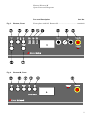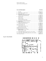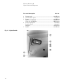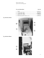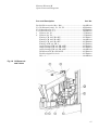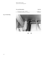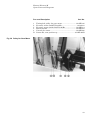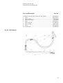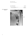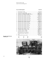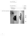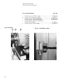
1
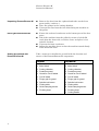
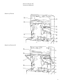
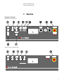
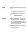
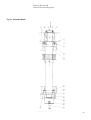
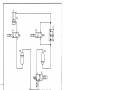
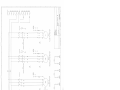
Exotom Exotom-M Instruction Manual Manual No.: 13817001 Date of Release 12.08.1998 Exotom/Exotom-M Instruction Manual Table of Contents Page User’s Guide .............................................................. 1 Reference Guide....................................................... 11 Always state Serial No and Voltage/frequency if you have technical questions or when ordering spare parts. You will find the Serial No. and Voltage on the type plate of the machine itself. We may also need the Date and Article No of the manual. This information is found on the front cover. The following restrictions should be observed, as violation of the restrictions may cause cancellation of Struers legal obligations: Instruction Manuals: Struers Instruction Manual may only be used in connection with Struers equipment covered by the Instruction Manual. Service Manuals: Struers Service Manual may only be used by a trained technician authorised by Struers. The Service Manual may only be used in connection with Struers equipment covered by the Service Manual. Struers assumes no responsibility for errors in the manual text/illustrations. The information in this manual is subject to changes without notice. The manual may mention accessories or parts not included in the present version of the equipment. The contents of this manual is the property of Struers. Reproduction of any part of this manual without the written permission of Struers is not allowed. All rights reserved. © Struers 1998. Struers A/S Valhøjs Allé 176 DK-2610 Rødovre/Copenhagen Denmark Telephone +45 36 70 35 00 Fax +45 38 27 27 01 Exotom/Exotom-M Instruction Manual Exotom/Exotom-M Safety Precaution Sheet To be read carefully before use 1. The operator(s) should be fully instructed in the use of the machine and its cut-off wheels according the Instruction Manual and the instructions on the cut-off wheels. 2. The machine must be placed on a safe and stable support. All safety functions and screws of the machine must be in working order. 3. Use only intact cut-off wheels. The cut-off wheels must be approved for min. 3400 rpm/63 m/s. 4. Observe the current safety regulations for handling, mixing, filling, emptying and disposal of the additive for cooling fluid. 5. Do not touch anything inside the cutting chamber while positioning the cut-off wheel with the button RAPID ADVANCE. 6. The sample must be securely clamped in the quick-clamping device or the like. Large or sharp samples must be handled in a safe way. 7. Protruding work pieces should be shielded or marked. 8. Do not put your hands through the rubber curtain during operation of the machine. 9. Do not open the protection screen before the cut-off wheel has stopped. 10. Struers recommends the use of exhaustion as the cutting materials may emit harmful gasses or dust. See the instructions of the cut-off wheel. The equipment is designed for use with consumables supplied by Struers. If subjected to misuse, improper installation, alteration, neglect, accident or improper repair, Struers will accept no responsibility for damage(s) to the user or the equipment. Dismantling of any part of the equipment, during service or repair, should always be performed by a qualified technician (electromechanical, electronic, mechanical, pneumatic, etc.). Exotom/Exotom-M Instruction Manual User’s Guide Table of Contents Page 1. Getting Started Checking the Contents of Packing ................................................... 3 Exotom ....................................................................................... 3 Exotom-M ................................................................................... 3 Recirculation Cooling Unit ........................................................ 3 Unpacking Exotom/Exotom-M ......................................................... 4 Placing Exotom/Exotom-M ............................................................... 4 Getting Acquainted with Exotom/Exotom-M .................................. 4 Details of Exotom ...................................................................... 5 Details of Exotom-M .................................................................. 5 Noise Level ........................................................................................ 6 Supplying Power ............................................................................... 6 Direction of the Cut-off Wheel .................................................. 6 Supplying Compressed Air ............................................................... 6 Connecting the Recirculation Unit .................................................. 6 2. Operation Using the Controls ............................................................................ 7 Front Panels of Exotom ............................................................. 7 Front Panel of Exotom-M .......................................................... 7 Front Panel Controls ........................................................................ 8 Changing the Cut-off Wheel ............................................................. 9 Clamping the Sample ....................................................................... 9 Positioning the Cut-off Wheel .......................................................... 9 Cutting on Exotom ............................................................................ 9 Starting the Cutting .................................................................. 9 Stopping the Cutting ................................................................. 9 Cutting on Exotom-M ..................................................................... 10 Starting the Cutting ................................................................ 10 Stopping the Cutting ............................................................... 10 Excicut ............................................................................................. 10 Flushing the Cutting Chamber ...................................................... 10 Refilling of Cooling Water .............................................................. 10 1 Exotom/Exotom-M Instruction Manual 2 Exotom/Exotom-M Instruction Manual 1. Getting Started Checking the Contents of Packing In the packing box you should find the following parts: Exotom 1 3 6 1 1 1 1 2 1 1 1 1 1 1 2 1 Exotom Cut-off wheels (81EXO, 83EXO and 86EXO) Cardboard flanges for cut-off wheels 81EXO, 83EXO and 86EXO Fork spanner (32 mm) for mounting of cut-off wheel Additive (1 l) for cooling water Socket spanner (19 mm) Hose for compressed air (3000 mm) Hose Clamps (12 mm) Hose connection Grease gun Hexagon spanner, 3 mm, for the quick clamping device Angled socket spanner, 13 mm, for the quick clamping device Crossbeam Hexagon spanner, 10 mm, for mounting crossbeam Screws for mounting crossbeam Set of Instruction Manuals Exotom-M 1 3 6 1 1 1 1 1 1 1 1 2 1 Exotom-M Cut-off wheels (81EXO, 83EXO and 86EXO) Cardboard flanges for above Fork spanner (32 mm) for mounting of cut-off wheel Additive (1 l) for cooling water Socket spanner (19 mm) Grease gun Hexagon spanner, 3 mm, for the quick clamping device Angled socket spanner, 13 mm, for the quick clamping device Crossbeam Hexagon spanner, 10 mm, for mounting crossbeam Screws for mounting crossbeam Set of Instruction Manuals Recirculation Cooling Unit 1 1 1 2 1 Recirculation cooling unit Lid for cooling unit Sieve for cooling water Plastic inserts for the tank Trolley for cooling unit 3 Exotom/Exotom-M Instruction Manual Unpacking Exotom/Exotom-M Placing Exotom/Exotom-M Getting Acquainted with Exotom/Exotom-M Remove the door from the cupboard and take out the loose parts (trolley, tank etc.). Place the pumps in the cutting chamber. Unscrew the nuts from the four bolts fixing the machine to the pallet. Fasten the enclosed crossbeam at the bottom part of the door posts. Lift of the machine from the pallet by means of a fork-lift truck from the front side, or with a crane, and place it in a suitable location. Unscrew the front crossbeam. Adjust the machine shoes so that the machine stands firmly. Then mount the door. Take a moment to familiarise yourself with the location and names of the Exotom/Exotom-M components. Exotom Exotom-M Front panel controls Front panel controls Main switch Main switch Cutting chamber Cutting chamber Protection guard Protection guard Guard for cut-off wheel Guard for cut-off wheel Cut-off wheel Cut-off wheel Finger grip for guard Finger grip for guard Spindle lock button Spindle lock button Cutting table Cutting table Quick-clamping device Quick-clamping device Flushing hose Flushing hose Cutting handle 4 Exotom/Exotom-M Instruction Manual Details of Exotom Details of Exotom-M 5 Exotom/Exotom-M Instruction Manual Noise Level Approx. 85 dB (A) measured at idle running, at a distance of 1.0 m/39.4” from the machine. Supplying Power IMPORTANT Check that the mains voltage corresponds to the voltage stated on the type plate on the side of the machine. Exotom/Exotom-M is factory mounted with electric cable. Mount a plug on the cable. Black and Brown: phase Yellow/green: earth Direction of the Cut-off Wheel Check that the cut-of wheel rotates in the direction indicated on the label attached to the inner guard of Exotom/Exotom-M. If the direction of rotation is incorrect, switch two of the phases. Supplying Compressed Air (Exotom Model only) Connecting the Recirculation Unit (Both Exotom and Exotom-M) 6 Press the hose connection of the hose for compressed air into the inlet of Exotom placed on the left side of the machine. Fasten it with a hose clamp (12 mm). Connect the other end of the hose to the compressed air source by means of a hose clamp (12 mm). Place a disposable plastic insert (EXOSP) in the tank and fold it over the edge. The pre-punched holes should be in front of the overflow aperture in the tank. Place the cooling unit on the trolley and fill it up with 65 l of water i.e. 8-10 cm from the upper edge. Add additive in the quantity which is stated on the bottle label and stir a little. Put the lid on the tank and place the sieve and the pumps in the lid. Connect the two inlet hoses to the pumps. Place the tank in the cupboard and adjust the outlet hoses so that they discharge into the sieve. Exotom/Exotom-M Instruction Manual 2. Operation Using the Controls Front Panel of Exotom Front Panel of Exotom-M 7 Exotom/Exotom-M Instruction Manual Front Panel Controls Name Key Function Exotom and Exotom-M Turns on the main power of the machine. The main switch is located on the left side of the machine. MAIN SWITCH Power POWER START STOP EMERGENCY STOP EXCICUT FLUSH PUMP 8 Turns on/off the power of the machine. A switch for daily use. The button lights when activated. Starts the machine, recirculation unit, and Excicut when in ONposition. The button lights green when the safety screen is closed and the button can be pressed. Stops the machine, recirculation unit, and Excicut when in ONposition. The button lights red when it can be activated. Interrupts all functions. A red light indicates that the button has been activated or overload of the motors. Pull the button to release the light. Starts/stops the Excicut motion of the cut-off wheel. The button lights when activated. Starts/stops the water flush. The button lights when activated. Name Key Function Exotom only FORCE RAPID ADVANCE RETRACT Adjusting knob for setting the force. Moves the cut-off wheel down towards the sample for as long as the button is pressed. The button lights when activated. When pressed shortly the cut-off wheel will return to its top position. At quick repress the return movement will stop. The button lights when activated. Moves the cut-off wheel down. The button lights when activated. FEED FEED RATE Adjusting knob for setting the feed speed. The knob is provided with a locking pin. When it is pressed down it prevents a set speed rate from being unintentionally changed. Exotom/Exotom-M Instruction Manual Changing the Cut-off Wheel Turn the finger grip to the left and swing the guard for the cut-off wheel open. Turn the cut-off wheel and press the button situated to the right so that it catches the flange and locks the spindle. Remove the nut by means of a fork spanner (32 mm). Remove the flange and the cut-off wheel. IMPORTANT Exotom/Exotom-M is left-hand threaded. Clamping the Sample Positioning the Cut-off Wheel Cutting on Exotom Starting the Cutting Place the sample between the clamp and the back stop. Push the clamp towards the sample, and lock the quick clamping device with the locking handle. After clamping you may lower the cut-off wheel into position, min. 1 mm above the sample, to test the correct position of the cut on the sample: Press the button RAPID ADVANCE, to lower the cut-off wheel. The cut-off wheel stops when the button is released. Leave the cut-off wheel in position before you press the button START . Stopping the Cutting Mount the new cut-off wheel with a cardboard washer on each side. Mount the flange and nut. Tighten carefully and close the guard. Position the cut-off wheel. Close the protection guard. Press the button START . The cut-off wheel starts rotating and the cooling water starts running. Press the button FEED ON/OFF and the cut-off wheel will slowly move down into the sample. Exotom automatically stops cutting when the sample is cut through. The cut-off wheel moves to its top position, stops rotating and the recirculation unit is turned off. The machine can always be stopped by pressing the button RETRACT ON/OFF. The machine can be stopped at any time during operation by pressing the button STOP . 9 Exotom/Exotom-M Instruction Manual Cutting on Exotom-M Starting the Cutting Close the protection guard. Press the button START . The cut-off wheel starts rotating and the cooling water starts running. Lower the cut-off wheel onto the sample by pulling the cutting handle slowly until it comes into contact with the sample. Do not apply much cutting pressure. Let the cut-off wheel work itself a little into the sample. Then increase the pressure and begin cutting. Keep the pressure constant. When the cut-off wheel is almost through the sample the cutting pressure should be reduced. Stopping the Cutting After cutting, return the cut-off wheel to top position. Stop the cut-off wheel and the cooling water by pressing STOP . Excicut To start and stop the Excicut feature, press the button EXCICUT ON/OFF Flushing the Cutting Chamber Refilling of Cooling Water To ensure a longer lifetime of your Exotom, Struers strongly recommends cleaning of the cutting chamber with the flushing hose every day: Point the flushing hose towards the button of the cutting chamber. Press the button FLUSH PUMP ON/OFF to turn the water on. Adjust the flow by means of the lever on the spray nozzle. Clean the cutting chamber thoroughly. Turn off the water by pressing the button FLUSH PUMP ON/OFF again. Refill cooling water in the tank by pouring the water through the sieve until the water level is 2-3 cm from the upper edge. NB! Never refill by pouring the water in the cutting chamber as it would be impossible to check the increasing level in the tank. IMPORTANT Always maintain the correct concentration of Struers Additive in the cooling water (percentage stated on the container of the Additive). Remember to add Struers Additive each time you refill with water. 10 Exotom/Exotom-M Instruction Manual Reference Guide Table of Contents Page 1. Accessories Cut-off Wheels................................................................................. 12 Accessories ...................................................................................... 13 2. Maintenance Cleaning .......................................................................................... 14 Recirculation Unit .......................................................................... 14 3. Service Every Week ..................................................................................... 15 Every 10th Week............................................................................. 15 Every 6th Month ............................................................................. 15 4. Technical Data ................................................................... 16 11 Exotom/Exotom-M Instruction Manual 1. Accessories Cut-off Wheels Application For direct and oscillating cutting of extremely hard steels (> 60HRC) 12 Dimensions Grindin g agent 350x2.5x32mm Al 2 O 3 300 mm Code 81EXO For direct and oscillating cutting of steels (<60HRC). Extremely hard (white cast iron) or ductile (18/8 or St60) steel types are cut with oscillating cutting. Gives good wheel economy 350x2.5x32mm Al 2 O 3 83EXO For cutting with Excicut. Universal cut off-wheel for steel-alloys less than 60 HRC and for general use. 350x2.5x32mm Al 2 O 3 8UEXO Primarily for oscillating cutting 350x2.5x32mm Al 2 O 3 of steels (<60HRC). Gives very good wheel economy 84EXO For direct and oscillating cutting in non-ferrous metals. Primarily for oscillating cutting 350x2.5x32mm SiC 86EXO For direct cutting of titanium and its alloys, as well as other non-ferrous metals 350x2.5x32mm SiC For direct cutting of sintered carbides and ceramics 305x1.8x32mm Diamond 25EXO 26EXO 350x1.8x32mm Diamond 56UNI 90EXO Exotom/Exotom-M Instruction Manual Accessories Specification Code Extra Clamping Table additional table for support of very large work pieces. UNFIT / EXOBA Quick Clamping Device UNIEL / UNIQI Clamping Tools for Exotom. UNIOF / EXOOF Fume Extractor Kit for Exotom (connecting tube ø50 mm). EXOKI Movable Cutting Table for long cuts. To move the specimen parallel to the cut-off wheel, thereby increasing the cutting length up to 150 mm. EXOLA Movable Cutting Table for parallel cuts. Positions the specimen at right angle to the cut-off wheel. With dial (setting 0.1 mm) movable up to 100 mm. EXOEL Disposable plastic inserts for the recirculation unit tank, 10 pcs. EXOSP 13 Exotom/Exotom-M Instruction Manual 2. Maintenance Cleaning Wash the slot between disc screen and cutting arm clean every day. The sieve must be emptied each day after a thorough washing down of the cutting chamber and, especially, the clamping table with the T-slots. The flushing pump must be removed and the sieve cleaned at least once a week, or as necessary, depending on use. Recirculation Unit 14 The cooling unit should be checked for cooling water every week and refilled when the flushing pump cannot reach the cooling water. Remember to use Struers Additive (pH should be around 9). Replace if pH is α 8.0. To check the concentration of Additive use a refractometer (0-10 Brix, see diagram.). Concentration = 2 x Brix. Exotom/Exotom-M Instruction Manual 3. Service Every Week Every 10th Week Grease the nut for cut-off wheel spindle. Use water resistant grease. Spindle tightening. Remove the fixed flange and wash off any dirt behind the flange. Grease the eccentric bearing. Use the grease from the grease gun supplied with the apparatus. You gain access to the grease nipple by dismounting the round cover plate in the right side of Exotom. On Exotom-M, the grease should be applied through the centre of the fixing piece of the lever. IMPORTANT When the machine is in continuous function for 8 hours or more, grease the eccentric bearing every day. Every 6th Month Grease hinges and lock for cut-off wheel screen. Belt tightening. Remove rear plate, release the motor; now tighten the belt using the bolt closest to the belt pulley. Remember to adjust the position of the motor so that it is at right angles to the belts before the motor is fixed again. Check the oil level. While the rear plate is removed the oil level can be checked on the reservoir tubes. Each mark corresponds to an extreme position of the cutting arm. R1 should be at the upper marking and R2 at the lower marking when the cut-off wheel is in its upper position. When filling up and changing the oil, please use Shell Tellus 32. Grease the power transmission part. While the rear plate is dismantled the guide block is greased. Use Shell Albida Grease LX for greasing the eccentric shaft and the quick clamping device as well as the power transmission part. If the cut-off wheel spindle is serviced, the gasket ring should be greased with special water resistant grease, e.g. Staburags NBU 12. 15 Exotom/Exotom-M Instruction Manual 4. Technical Data Subject Specifications Metric/ International Compressed air supply Cutting motor Cooling pump Capacity Flushing pump Capacity Cooling tank Volume Cut-off wheel Cutting speed Max. diameter of work piece Max. dimensions of work piece Cutting Tables Noise Level Voltage/ frequency/ Max. current consumption Dimensions and Weight 16 US Pressure: 6-9.9 bar Consumption: approx. 4 l/min 5.5 kW 7.5 HP 350 mm x 32 mm x 2.5 mm 13.8" x 1.25" x 0.1" 110 mm 4.3" Approx. 80 l/min (50 Hz) Approx. 96 l/min (60 Hz) Approx. 50 l/min (50 Hz) Approx. 60 l/min (60 Hz) 65 l 50 m/s at 2675 rpm Max. length of cut, for a work piece 250 mm 1.6" Max. thickness of cut, for a work piece approx. 40 mm Thickness 140 mm 5.5" Width 475 mm 18.7" Length 600 mm 23.6" (longer sections of bar and rod can be accommodated) Cutting table 300 x 300 mm (12" x 12") (6" x 12") Extra table 150 x 300 mm Approx.85 dB (A) measured at idle running, at a distance of 1.0 m/39.4" from the machine. 3 x 200 V/50-60 Hz 24.8 A 3 x 220 V/50-60 Hz 23.5 A 3 x 380 V/50 Hz 13.8 A 3 x 415 V/50 Hz 13.8 A 3 x 440 V/60 Hz 13.6 A 3 x 480 V/60 Hz 13.6 A 3 x 500 V/50 Hz 11.0 A Width 660 mm 26" Depth 900 mm 35.4" Height 1650 mm 65" Weight 390 kg Exotom Exotom-M Spare Parts and Diagrams Manual No.: 13817001 Date of Release: 12.08 1998 Revised: 01.06.2002 Exotom/Exotom-M Spare Parts and Diagrams Always state Serial No and Voltage/frequency if you have technical questions or when ordering spare parts. The following restrictions should be observed, as violation of the restrictions may cause cancellation of Struers legal obligations: Instruction Manuals: Struers Instruction Manual may only be used in connection with Struers equipment covered by the Instruction Manual. Service Manuals: Struers Service Manual may only be used by a trained technician authorised by Struers. The Service Manual may only be used in connection with Struers equipment covered by the Service Manual. Struers assumes no responsibility for errors in the manual text/illustrations. The information in this manual is subject to changes without notice. The manual may mention accessories or parts not included in the present version of the equipment. The contents of this manual is the property of Struers. Reproduction of any part of this manual without the written permission of Struers is not allowed. All rights reserved. © Struers 2002. Struers A/S Valhøjs Allé 176 DK-2610 Rødovre/Copenhagen Denmark Telephone +45 36 70 35 00 Telefax: +45 38 27 27 01 Exotom/Exotom-M Spare Parts and Diagrams 1. Spare parts and Diagrams Table of contents Photos and drawings Fig 1 2 3 4 5 6 8 9 10 11 12a/b 13 14 15 16 17 18 19 20 21 22 23 24 25 26 27a/b 28 29 30 31 32 33 34 35 36 37a/b 38 50 51 51-M 52 53 Title Exotom, complete Exotom-M, complete Exotom, front Exotom-M, front Fastening the cutting wheel Cleaning the cutting table Exhaust Motor, details Front, details Lights, details V-belt, belt guard Protection screen Mounting strip, horizontal Mounting strip, oblique Flange and spindle Cutting wheel guard Oil reservoir and valves Belt pulley Pulley for gear motor Cutting table Cooling tank and trolley Hose branch Hose branch Hexagonal nipple Tube branch Cylinder and shock absorber Mounting plate for electronics and hydropneumatics Water expeller/filter unit Emergency stop, Manometer Throttle valves Main switch and fuses Transformers and relays PCB console Door, locking device Arm Belts V-belt motor, detail Spindle arm Eccentric shaft Eccentric shaft, Exotom-M Spindle lock case Quick-clamping house 1 Exotom/Exotom-M Spare Parts and Diagrams List of special parts for Exotom-M Diagrams Exotom Exotom-M Pneumatic diagram ......................................................... 13810147A Power circuit diagram ..................................................... 13810065A Wiring diagram................................................................ 13810266B Control circuit diagram for auto model .......................... 13810272D Logic control diagram ...................................................... 13810384C Component illustration logic control board.................... 13810388C Wiring diagram, Exotom-M................................................ 14100105 Control circuit diagram, Exotom-M ................................ 14100111D Diagram for inductive supply and relay, Exotom-M...... 14100150B Component Illustration, Exotom-M................................... 14100155 The drawings are not to scale. Some of the drawings may contain position numbers not used in connection with this manual. 2 Exotom/Exotom-M Spare Parts and Diagrams Photos and Drawings 3 Exotom/Exotom-M Spare Parts and Diagrams Pos. and Description Fig. 1 Cat. No. Exotom, complete ➁ ➀ ➃ ➄ ➆ ➇ ➂ ➅ ➉ ➈ Fig. 2 Exotom-M, complete ➁ ➀ ➃ ➄ ➆ ➇ ➂ ➅ ➉ ➈ 4 Exotom/Exotom-M Spare Parts and Diagrams Pos. and Description Fig. 3 Exotom, Front Fig. 4 Exotom-M, Front Cat. No. Front plate with foil, Exotom-M ........................................ 14100082 5 Exotom/Exotom-M Spare Parts and Diagrams Pos. and Description 1 Fig. 5 Fastening the Cutting Wheel Fig. 6 Cleaning the Cutting Table 6 Cat. No. Rubber cover, lower...................................................... 13810726 Exotom/Exotom-M Spare Parts and Diagrams Pos. and Description Fig. 8 Cat. No. Exhaust 7 Exotom/Exotom-M Spare Parts and Diagrams Pos. and Description 1 1 2 3 3 4 5 6 7 Cat. No. Top rear plate ............................................................... 13819053 Back Plate (Removed = not visible on figure) ............. 13819044 Lower Casing............................................................... R3819049 Mounting Plate (Hidden = not visible on figure) ........ 13819054 Top plate ....................................................................... 13819045 Cover for pointer .......................................................... 13819051 Pointer .......................................................................... 13819002 Dial for pointer ........................................................... 381MP295 Stop for protection screen .......................................... 381MP007 Stop for spindle arm, Exotom-M.................................. 14108001 8 Cast bed ........................................................................ 13819033 Column (Exotom-M) ..................................................... 14108004 Bumper (Exotom-M).................................................... 2GS00315 9 Spring............................................................................ 13810135 10 Thread plate for lower plate (9.2)................................ 13818002 Grease gun.................................................................. 381MP415 Cardboard discs, 25 pcs.............................................. 381MP431 Angle for pulley .......................................................... 381MP387 11 Pulley ............................................................................ 13810129 12 Gas Spring Replacement Kit, see fig. 15..................... 13810115 Fig. 9 8 Motor, Details Exotom/Exotom-M Spare Parts and Diagrams Pos. and Description Cat. No. 1 2 2 4 Handle......................................................................... 2GH20002 Front Plate without foil ............................................. 381MP353 Front plate foil.............................................................. 13810209 Emergency stop push button without switch element S4 ........................................ 381MP439 5 Bourns Dial................................................................. 381MP412 Cable entry ................................................................. 381MP291 Fork wrench.................................................................2GR00232 Socket spanner for jaw................................................2GR00313 6 Stop knob for protection screen ................................... 13810490 7 Manometer.................................................................... 13810238 S1,S5,S6 Push button S1, S5, S6 without switch element.............................................. 381MP249 S2 Push button, S2 .......................................................... 381MP250 S3 Push button, S3 .......................................................... 381MP251 Push button symbol, set............................................... 13810230 S1-S6 Push button cap. ..................................................... 2SA30102 S7-S9 Push button S7-S9 .................................................. 2SA40066 S7-S9 Push button cap, S7-S9........................................... R3810258 Bulb, S7-S9 ................................................................. 2HG10002 Inset (3 pcs.) S7-S9...................................................... 2SA41200 B Sensor B1, Exotom, protective cover closed ............381MP436A B Sensor B1, Exotom-M, protective cover closed ......... 381MP336 H4 Lamp H4 (red) ............................................................ 2HK20342 Fig. 10 Front, Details 9 Exotom/Exotom-M Spare Parts and Diagrams Pos. and Description 1 2 3 4 7 Fig. 11 Lights, Details 10 Cat. No. Sweep strip ................................................................. 381MP363 Intermediate plate........................................................ 13819064 Lamp ........................................................................... 381MP264 Bulb for 381MP264 .................................................... 381MP265 Glass for 381MP264 ...................................................2HW00002 Lamp angle/plate.......................................................... 13819068 Lamp console ................................................................ 13819067 Bumper ........................................................................ 2GS00120 Baffle........................................................................... 381MP426 Exotom/Exotom-M Spare Parts and Diagrams Pos. and Description 1 2 3 4 5 6 Cat. No. Baffle........................................................................... 381MP361 V-belt guard, front....................................................... R3819048 V-belt guard, upper .................................................... 381MP364 V-belt guard, lower..................................................... 381MP365 Rubber cover, upper ..................................................... 13810725 Mounting strip for rubber cover ................................ 381MP368 Fig. 12a V-belt, Guard Fig. 12b V-belt, Wheel 11 Exotom/Exotom-M Spare Parts and Diagrams Pos. and Description 1 2 3 5 7 6 Fig. 13 Protection Screen 12 Cat. No. Protection screen, complete ....................................... 381MP390 Window pacton ........................................................... 381MP032 Protection rail............................................................... 13818002 Rubber plate ............................................................... 381MP036 Bolt, with washer ....................................................... 381MP427 Slide strip complete...................................................... 13810464 Sealing band for window, 2 m ..................................... 2IP00401 Window strip, horizontal ........................................... 381MP040 Window strip, lower vertical...................................... 381MP041 Window strip, upper vertical ..................................... 381MP042 Exotom/Exotom-M Spare Parts and Diagrams Pos. and Description 1 2 3 4 Cat. No. Rubber plate ................................................................. 13810515 Mounting strip, horizontal......................................... 381MP370 Mounting strip, vertical, right hand side.................. 381MP371 Mounting strip, vertical, left hand side .................... 381MP369 Fig. 14 Mounting Strip, Horizontal 13 Exotom/Exotom-M Spare Parts and Diagrams Pos. and Description 1 2 3 4 5 6 Fig. 15 Mounting Strip, Oblique 14 Cat. No. Mounting strip, oblique.............................................. 381MP369 Gas Spring 150N Lift-o-Mat 580 ................................ 2YS00422 Bottom holder, left-hand side ...................................... 13810149 Bottom holder, Right-hand side .................................. 13810148 Shaft for top holder ...................................................... 13810143 Top holder for U-rail .................................................... 13810139 Shaft for bottom holder ................................................ 13810144 Exotom/Exotom-M Spare Parts and Diagrams Pos. and Description 1 2 3 4 4 Cat. No. Flange, inside ............................................................. 381MP433 Flange, outside ........................................................... 381MP043 Spindle nut (left-hand tread) ...................................... 13810122 Cutting wheel guard .................................................. 381MP394 Cutting wheel guard, complete.................................... 13810403 Fig. 16 Flange and Spindle 15 Exotom/Exotom-M Spare Parts and Diagrams Pos. and Description 1 2 3 4 5 6 B Fig. 17 Cutting Wheel Guard 16 Cat. No. Door for cutting wheel guard..................................... 381MP429 Hinge for cutting wheel guard................................... 381MP078 Sensor strap.................................................................. 13810453 Door locking device..................................................... 381MP082 Guide for strap ........................................................... 381MP420 Baffle and spark plate................................................ 381MP361 Sensor B2,................................................................... 381MP263 Exotom/Exotom-M Spare Parts and Diagrams Pos. and Description Cat. No. R1+R2 Oil reservoir (R1 + R2) ......................................... 381MP338 Y1+Y2 Solenoid valve, Y1, Y2, Y5 ................................... 2YM10001 Y3 Solenoid valve, Y3 ...................................................... 2YM10005 Y4 Solenoid valve, Y4 ...................................................... 394MP058 1 Silencer for Y3 ............................................................. 2YL00010 2 Silencer for Y4 ............................................................. 2YL00005 Fitting, CK-1/8-PK-6-KU ............................................2NF20017 Fitting, CK-1/8-PK-4-KU ........................................... 381MP194 Fitting, CK-1/8-PK-3-KU ............................................2NF20090 Fitting, ACK-1/4-PK-4 ................................................2NF10018 Angle fitting GCK-1/4-PK-4-KU .................................2NF10087 Angle fitting GCK-1/8-PK-6-KU .................................2NF20054 Angle fitting GCK-1/8-PK-4-KU ................................ 381MP199 Distributor FCK-3-PK-6-KU.......................................2NF20104 Double nipple E-1/8-1/8...............................................2NF40011 Oil, 1 l.......................................................................... 381MP204 Fig. 18 Oil Reservoir and Valves 17 Exotom/Exotom-M Spare Parts and Diagrams Pos. and Description 1 2 Fig. 19 Belt Pulley 18 Cat. No. Timing belt pulley, spindle ........................................ 381MP104 Timing Belt 322L 100, L=819,15 .................................2JT00025 Exotom/Exotom-M Spare Parts and Diagrams Pos. and Description 1 2 2 3 4 B Cat. No. Timing belt pulley for gear motor ............................. 381MP106 Eccentric motor 3x220V/50-60Hz ................................ 13810810 Eccentric motor 3x380-500V/50-60Hz ....................... 381MP214 Motor bracket ............................................................. 381MP283 Console for sensor ...................................................... 381MP296 Sensor B3, arm position up......................................381MP436B Fig. 20 Pulley for Gear Motor 19 Exotom/Exotom-M Spare Parts and Diagrams Pos. and Description 1 1 2-8 3-6 7 Fig. 21 Cutting Table 20 Cat. No. UNIFT, Cutting table with 10mm T-slots .................. 03816901 UNIBA; Replacement Stainless Steel Bands.............. 05336905 Fixed jaw, with T-screws for 10mm T-slots ............... R5330310 UNIRI, Quick-clamping device, complete, right for 10mm T-slots ................................ 05336907 UNILE, Quick-clamping device, complete, left for 10mm T-slots ................................... 05336906 Exotom/Exotom-M Spare Parts and Diagrams Pos. and Description Cat. No. 1 Cooling tank ............................................................... 381MP140 Lid for cooling Tank ................................................... 381MP142 2 Trolley ......................................................................... 381MP430 3 Lid ............................................................................... 381MP142 4 Sieve for return water .................................................. 14980071 5 Elbow joint for flush pump (1/2”).............................381MP144A 6 Elbow joint for cooling pump (3/4”) .........................381MP145A 7 Pump, cooling. (3 x 220 - 240V/ 50 Hz)....................381MP408A 7 Pump, cooling. (3 x 380 - 440V/ 50 Hz)....................381MP408A 7 Pump, cooling. (3 x 200 - 220V/ 60 Hz)....................381MP409A 7 Pump, cooling. (3 x 380 - 480V/ 60 Hz)....................381MP409A 8 Pump, flushing (3 x 200 - 240V/ 50-60Hz) ..............381MP410A 8 Pump, flushing (3 x 380 - 480V/ 50-60Hz) ..............381MP410B Sieve for Pump, 2AB4 (Ø99) ........................................ 14980074 9 Clamp for sieve............................................................2NS20215 10 Holder for sieve ..........................................................315MP052 Fig. 22 Cooling Tank and Trolley 21 Exotom/Exotom-M Spare Parts and Diagrams Pos. and Description Cat. No. 1+2 Hose branch with union nut and gasket ................... 2NG20065 3 Hose ............................................................................ 2NU20325 4 Hose clamp...................................................................2NS12409 5 Hose branch ................................................................ 2NG20070 6 Elbow .......................................................................... 2NG10002 7 Nipple............................................................................ 13810682 8 Nut .............................................................................. 381MP152 9 Reduction socket......................................................... 381MP153 10 Delivery pipe................................................................2NP10014 11 Elbow, 90° ................................................................... 2NG10040 12 Distribute branch ......................................................... 13810680 13 Elbow, 90° ..................................................................... 13810684 14 Delivery hose .............................................................. 2NU90020 15 Elbow ...........................................................................2NF40098 16 Nipple.......................................................................... 381MP333 Fig. 23 Hose Branch 22 Exotom/Exotom-M Spare Parts and Diagrams Pos. and Description Cat. No. 1+2 Hose branch with union nut and gasket ................... 2NG20063 3 Hose ............................................................................ 2NU20316 4 Hose clamp...................................................................2NS11309 5 Reducing nipple ............................................................ 13810689 6 Hose ............................................................................ 2NU90021 7 Hose branch .................................................................2NF40086 8 Hose clamp...................................................................2NS11309 9 Hose ............................................................................ 2NU29310 10 Water gun ................................................................... 381MP168 Fig. 24 Hose Branch 23 Exotom/Exotom-M Spare Parts and Diagrams Pos. and Description 1 2 3 4 Fig. 25 Hexagonal Nipple 24 Cat. No. Hexagonal nipple.......................................................... 13810688 Elbow (67,5°) with rubber ring .................................. 2NG20567 Elbow (15°) with rubber ring ..................................... 2NG20515 Elbow (45°) with rubber ring ..................................... 2NG20545 Exotom/Exotom-M Spare Parts and Diagrams Pos. and Description 1 2 Cat. No. Branch......................................................................... 381MP418 Outlet hose.................................................................. 381MP419 Fig. 26 Tube Branch 25 Exotom/Exotom-M Spare Parts and Diagrams Pos. and Description Cat. No. Cy Cylinder (Cy) ............................................................... R3810540 Fig. 27a Cylinder Pos. and Description 1 2 3 4 5 6 Fig. 27b Shock Absorber Fig. 27a 26 Cylinder Cat. No. Shock absorber ............................................................ 2GS10001 Top Bracket ................................................................ 381MP321 Bottom Bracket .......................................................... 381MP322 Distance bush ............................................................. 381MP323 Bolt, upper .................................................................. 381MP324 Bolt, lower................................................................... 381MP325 Fig. 27b Shock Absorber Exotom/Exotom-M Spare Parts and Diagrams Pos. and Description Cat. No. 1 Mounting plate for electronics and hydro-pneumatics......................................................... 13819014 Y5 Solenoid valve (Y1, Y2 and Y5).................................. 381MP183 Fig. 28 Plate for Electronics and Hydro-pneumatics 27 Exotom/Exotom-M Spare Parts and Diagrams Pos. and Description Cat. No. V3 Water expeller/filter unit, V3 ..................................... 2YF00001 Glass for 381MP189 ................................................... 375MP200 Fig. 29 Water Expeller/ Filter Unit 28 Exotom/Exotom-M Spare Parts and Diagrams Pos. and Description 1 2 V2 V4 Cat. No. Manometer holder .......................................................2NS11309 Emergency stop switch element, S4.......................... 381MP440 Reduction valve .......................................................... 368MP330 Non-return valve (V4) .................................................2YH00012 Fig. 30 Emergency Stop, Manometer 29 Exotom/Exotom-M Spare Parts and Diagrams Pos. and Description V1 1 2 3 Fig. 31 Throttle Valves 30 Cat. No. Throttle/one way restrictor valve ...............................2YH00010 Angle for valve............................................................ 381MP396 Shaft with toothed wheel ........................................... 381MP397 Toothed wheel for valve 13810375 Exotom/Exotom-M Spare Parts and Diagrams Pos. and Description 1 1 3 SO Cat. No. Fuse holder, F1, F2 ..................................................... 2XS12004 Fuse F1, F2 ..................................................................2FU14150 Angle for 381MP189....................................................2NF10107 Main switch, SO ......................................................... 260MP135 Fig. 32 Main Switch and Fuses 31 Exotom/Exotom-M Spare Parts and Diagrams Pos. and Description 1 1 4 4 5 5 5 5 5 5 5 5 5 5 5 5 5 5 5 5 2 2 3 1 Fig. 33 Transformers and Relays 32 Cat. No. Transformer 220V ........................................................ 12601029 Transformer, 380-500V .............................................. 381MP223 Contactor, 220V/50-60Hz, K3, K4 .............................2KM10232 Contactor, 380-500V/50-60Hz, K3, K4 ......................2KM10232 Thermal relay, TI16 0.13-0.20A ................................ 381MP345 Thermal relay, TI16C 0.13-0.20A............................... 2FS00120 Thermal relay, TI16 0.19-0.29A ..............................394MP050A Thermal relay, TI16C 0.19-0.29A............................... 2FS00130 Thermal relay, TI16 0.27-0.42A ..............................394MP050A Thermal relay, TI16C 0.27-0.42A............................... 2FS00123 Thermal relay, TI16 0.4-0.62A .................................. 381MP234 Thermal relay, TI16C 0.4-0.62A................................. 2FS00123 Thermal relay, TI16 0.6-0.92A .................................. 381MP230 Thermal relay, TI16C 0.6-0.92A................................. 2FS00124 Thermal relay, TI16 4.0-6.2A ..................................... 2FS00129 Thermal relay, TI16C 4.0-6.2A................................... 2FS00129 Thermal relay, TI16 6.0-9.2A .................................... 381MP233 Thermal relay, TI16C 6.0-9.2A................................... 2FS00130 Thermal relay, TI16 11-16A ...................................... 381MP233 Thermal relay, TI16C 11-16A..................................... 2FS00132 Auxiliary switch, NO K2............................................ 2KH00111 Auxiliary switch, NC K4 ............................................ 2KH00112 Barring device for contactor ...................................... 2KH10100 Contactor K2, K5, K6 or K7....................................... 376MP110 Rail ..............................................................................2KM10232 Mains/24V-Connector Kit ............................................ 13812902 Exotom/Exotom-M Spare Parts and Diagrams Pos. and Description Cat. No. 1 Control PCB (Exotom)................................................ 381MP386 Control PCB (Exotom-M) ............................................. 14100140 2 Switch element, S1..................................................... 381MP246 3 Switch element, S2, S3............................................... 381MP247 4 Switch element, S5, S6............................................... 381MP248 5 Flexible PCB................................................................. 13813376 6 Timer, A2 .................................................................... 381MP266 Socket for A2................................................................2KT90411 7 Angle plate for PCB.................................................... 381MP011 8 Tunnel for hydro-pneumatics ...................................... 13810036 9 Ammeter console ........................................................ 381MP015 10 Ammeter, 220V............................................................. 13810232 Ammeter, 380-500V ..................................................... 13810233 Bulb, S1, S3, S5, S6, S2.............................................. 2HK13004 Fig. 34 PCB Console 33 Exotom/Exotom-M Spare Parts and Diagrams Pos. and Description 1 2 3 Fig. 35 Door, Locking Device 34 Cat. No. Door............................................................................... 13819035 Locking device ............................................................ 381MP271 Distance plate............................................................... 13818039 Vibration damper ......................................................... 13810840 Connection box ........................................................... 381MP274 Exotom/Exotom-M Spare Parts and Diagrams Pos. and Description Cat. No. 1 Arm with bolt.............................................................. 381MP391 2 Guide block ................................................................. 381MP392 3 Arm pedestal ................................................................ 13819061 4 Shaft for arm ................................................................ 13810571 5+8 Fork arm for cylinder ................................................... 13810583 1 Bearing bracket .......................................................... 381MP305 7 Shaft for bearing brackets ........................................... 13810556 Bushing for shaft.......................................................... 13810557 Radial flexible bearing for cylinder bottom .............. 381MP443 9 Fitted bolt M10x12x20 .................................................2JT11220 Fig. 36 Arm 35 Exotom/Exotom-M Spare Parts and Diagrams Pos. and Description 1 2 3 3 3 Fig. 37a V-belts 36 Cat. No. V-belts (3 pcs.), 50Hz, L=1202 .................................... 2JD00002 Pulley for cutting motor 50Hz ................................... 381MP107 Cutting motor 3x200-220V/50Hz.............................381MP210A Cutting motor 3x220-220V/60Hz.............................381MP210B Cutting motor 3x380V-415V/50Hz + 3x440V-480V/60Hz..................................................... 381MP211 Cutting motor 3x500V/50Hz ...................................... 381MP212 Fig. 38 V-belt Motor, Detail Exotom/Exotom-M Spare Parts and Diagrams Pos. and Description 1 2 4 5 6 Cat. No. Timing belt, 60Hz 1200-8M-30 RPP............................2JT11200 Pulley for cutting motor, 60Hz .................................. 381MP405 Motor plate ................................................................. 381MP424 Motor base plate/belt tightener .................................. R3818044 Idler, complete, 60 Hz ................................................ 381MP399 Fig. 37b Toothed Belts 37 Exotom/Exotom-M Spare Parts and Diagrams Pos. and Description 1 2 3 4 5 7 8 9 10 11 12 13 14 15 38 Cat. No. Spindle arm with brass bearing and eccentric shaft ..................................................... 381MP060 Spindle shaft w. pin .............................................381MPXX13M Ball bearing, 6207-2RS ...............................................2BK00107 Ball bearing, 6006-2RS ...............................................2BK00080 Sealing ring, steel......................................................... 13810790 Thrust collar ................................................................2GF51019 Circlip........................................................................... 2ZL20550 Circlip........................................................................... 2ZL10300 O-ring (35.1 x 1.6 mm) (10 pcs)....................................2IO16030 Lock nut ........................................................................ 13810792 V-belt pulley for spindle, 50 Hz ................................. 381MP401 Timing belt pulley for spindle, 60 Hz........................ 381MP406 Washer 21/37x3 ........................................................... 2ZA10020 Key (A 8x7x36) for pulleys (2 pcs) .............................. 2ZF10836 Outer ring ..................................................................... 13810791 Sealing ring ................................................................ 381MP411 Washer and screw for spindle.................................... 381MP450 Exotom/Exotom-M Spare Parts and Diagrams Fig. 50 Spindle Arm 39 Exotom/Exotom-M Spare Parts and Diagrams Pos. and Description 1 2 3 4 5 6 7 8 10 11 12 13 14 15 20 21 22 23 40 Cat. No. Spindle arm with brass bearing and eccentric shaft ..................................................... 381MP060 Eccentric shaft (cannot be ordered separately, part of 381MP60) Washer with key........................................................... 13810773 Lock nut ....................................................................... 2TF02515 Lock washer.................................................................. 2ZI02512 Distance ring, outer...................................................... 13810770 Distance ring with key ............................................... 381MP376 Cover ring ................................................................... 381MP377 Ball bearing, 6205-2RS ...............................................2BK00055 Ball bearing, 6006-2RS ...............................................2BK00080 Thrust collar (4 pcs.) ...................................................2GF51019 Circlip.......................................................................... 381MP098 Left arm for motor plate ............................................ 381MP099 Circlip........................................................................... 2ZL10250 Console for pointer shaft............................................ 381MP113 Pointer shaft ............................................................... 381MP114 Distance ring with key ............................................... 381MP376 Grease nipple, type B1, straight (6 mm)................... 2GN20002 Exotom/Exotom-M Spare Parts and Diagrams Fig. 51 Eccentric Shaft 41 Exotom/Exotom-M Spare Parts and Diagrams Pos. and Description Fig. 51-M 42 Eccentric Shaft, Exotom-M Cat. No. Exotom/Exotom-M Spare Parts and Diagrams Pos. and Description 1 2 3 4 Cat. No. Spindle lock case ........................................................ 381MP083 Dowel w. circlip ............................................................ 13810439 Spring............................................................................ 13680095 Knob ............................................................................ 2GH00001 Fig. 52 Spindle Lock Case 43 Exotom/Exotom-M Spare Parts and Diagrams Pos. and Description 1 2 3 4 5 6 7 8 9 10 11 12 13 14 15 16 Fig. 53 Quick-clamping House 44 Cat. No. Quick-clamping house (cast), right............................ 381MP124 Quick-clamping house (cast), left .............................. 381MP138 Guide pin ...................................................................... 13810085 Handle for guide pin .................................................. 381MP126 Eccentric shaft, complete ............................................. 15110025 Handle rod .................................................................... 13810087 Knob ............................................................................ 2GH00180 Clamping ring (for 2 units) ........................................ 315MP005 Clamping Spring (2 pcs)............................................... 12150155 Jaw for QCD, left.......................................................... 15330311 Jaw for QCD, right ....................................................... 15330312 Base plate with dowel pins for 10mm T-slots ............. 15110027 Distance tube...............................................................2GB01155 Pawl (2 pcs)................................................................. 381MP134 Short T-headed screw with washer and cap nut ...... 381MP135 Scraper ring (2 pcs) ...................................................... 2IT00009 Exotom/Exotom-M Spare Parts and Diagrams List of Special Parts for Exotom-M Console for bellow ............................................................... 13810595 Handle ................................................................................. 14109002 51M16 Arm for Handle....................................................... 14109001 51M17 Attachment, left...................................................... 14108003 51M18 Guide for arm ......................................................... 14109007 51M19 Attachment, right................................................... 14109003 See Fig. 10 See Fig. 54 B 1 Sensor B1, protective screen closed........................... 381MP336 Control PCB.................................................................. 14100140 See Fig. 54 45 Exotom/Exotom-M Spare Parts and Diagrams 46 Exotom/Exotom-M Spare Parts and Diagrams Diagrams 47 Dansk Overensstemmelseserklæring Fabrikant Struers A/S Valhøjs Allé 176, DK-2610 Rødovre, Danmark Telefon 36 70 35 00 erklærer herved, at Produktnavn: Type nr.: Maskintype: S Exotom 381 Skæremaskine er i overensstemmelse med følgende EU-direktiver: Maskindirektivet 89/392/EØF, 91/368/EØF, 93/44/EØF og 93/68/EØF efter følgende norm(er): EN292-1:1991, EN292-2:1993/A1:1995, EN294:1993, EN349:1994, EN418:1994, EN954-1:1997, EN1037:1996, EN11200:1996, EN60204-1:1997:ED4. EMC-direktivet 89/336/EØF og 92/31/EØF efter følgende norm(er): EN50081-1:1991, EN50081-2:1993, EN50082-1:1992, EN50082-2:1994. Lavspændingsdirektivet 73/23/EØF og efter følgende norm(er): EN60204-1:1997:ED4. Supplerende oplysninger Endvidere overholdes de amerikanske normer: NEPA 79-1997, UL508 ED14 22-2-88. Ovenstående overensstemmelse(r) er erklæret iflg. den globale metode, modul A Dato: 20.01.1999 English Klaus Kisbøll, udviklingschef, Struers A/S Declaration of Conformity Manufacturer Struers A/S Valhøjs Allé 176 DK-2610 Rødovre, Denmark Telephone 36 70 35 00 Herewith declares that Product Name: Type No: Machine Type: S Exotom 381 Cut-off machine is in conformity with the provisions of the following directives: Safety of Machinery 89/392/EEC, 91/368/EEC, 93/44/EEC and 93/68/EEC according to the following standard(s): EN292-1:1991, EN292-2:1993/A1:1995, EN294:1993, EN349:1994, EN418:1994, EN954-1:1997, EN1037:1996, EN11200:1996, EN60204-1:1997:ED4. EMC-Directive 89/336/EEC and 92/31/EEC according to the following standard(s): EN50081-1:1991, EN50081-2:1993, EN50082-1:1992, EN50082-2:1994. Low Voltage Directive 73/23/EEC according to the following standard(s): EN60204-1:1997:ED4. Supplementary Information The equipment complies with the American standards: NEPA 79-1997, UL508 ED14 22-2-88. The above has been declared according to the global method, module A Date: 20.01.1999 eu_erkl\381c.doc Klaus Kisbøll, R&D Manager, Struers A/S Deutsch Konformitätserklärung Hersteller Struers A/S Valhøjs Allé 176, DK-2610 Rødovre, Danmark Telefon 36 70 35 00 erklärt hiermit, daß Produktname: Typennr.: Maschinenart: S Exotom 381 Trennmaschine konform ist mit den einschlägigen EG-Richtlinien Sicherheit der Betriebsanlage 89/392/EWG, 91/368/EWG, 93/44/EWG, und 93/68/EWG gemäß folgender Normen: EN292-1:1991, EN292-2:1993/A1:1995, EN294:1993, EN349:1994, EN418:1994, EN954-1:1997, EN1037:1996, EN11200:1996, EN60204-1:1997:ED4. EMC-Direktive 89/336/EWG und 92/31/EWG gemäß folgender Normen: EN50081-1:1991, EN50081-2:1993, EN50082-1:1992, EN50082-2:1994. Niederspannungs Direktive 73/23/EWG gemäß folgender Normen: EN60204-1:1997:ED4. Ergänzungs-information Die Maschine entspricht ebenfalls den amerikanischen FCC Normen: NEPA 79-1997, UL508 ED14 22-2-88. Die obenstehende Konformität ist in Folge der globalen Methode, Modul A erklärt Datum: 20.01.1999 Français Klaus Kisbøll, Entwicklungsleiter, Struers A/S Déclaration de conformité Fabricant Struers A/S Valhøjs Allé 176 DK-2610 Rødovre, Denmark Téléphone 36 70 35 00 Déclare ci-après que Nom du produit: Type no: Type de machine: S Exotom 381 Machine pour le tronçonnage est conforme aux dispositions des Directives CEE suivantes: Sécurité des machines 89/392/CEE, 91/368/CEE, 93/44/CEE et 93/68/CEE conforme aux normes suivantes: EN292-1:1991, EN292-2:1993/A1:1995, EN294:1993, EN349:1994, EN418:1994, EN954-1:1997, EN1037:1996, EN11200:1996, EN60204-1:1997:ED4. Directive EMC 89/336/CEE et 92/31/CEE conforme aux normes suivantes: EN50081-1:1991, EN50081-2:1993, EN50082-1:1992, EN50082-2:1994. Directive de basse tension 73/23/CEE conforme aux normes suivantes: EN60204-1:1997:ED4. Informations supplémentaires L’équipement est conforme aux standards américains: NEPA 79-1997, UL508 ED14 22-2-88. La déclaration ci-dessus a été faite d’après la méthode globale, module A Date: 20.01.1999 eu_erkl\381c.doc Klaus Kisbøll, Chef du service developpement, Struers A/S