1
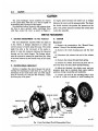
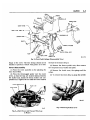
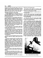
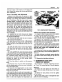
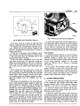
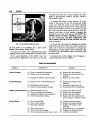
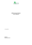
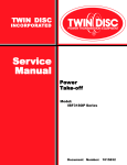
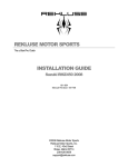
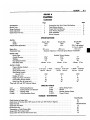
CLUTCH
6-1
GROUP 6
CLUTCH
CONTENTS
Page
Specifications. . . . . . . . . . . . . . . . . . . . . . . . . . . . . . . . .
Special Tools.
Torque Reference
Clutch Adjustment.
Clutch Pedal Free Play
Pa§*
1
1
1
2
2
Transmission Main Drive Pinion Pilot B u s h i n g . . . . . . . . .
Clutch Release Bearing
Torque Shaft and B e a r i n g s . . . . . . . . . . . . . . . . . . . . . .
Clutch Housing Alignment.
Clutch installation
Service Diagnosis
5
6
6
6
7
8
SPECIFICATIONS
CLUTCH
Make.....................:...
Model
Vehicle Model Application
.
Engine Size.
Transmission Type. . . . . . . V . . . . . . . . . . . . . . . .
CLUTCH DISC
Facing Type.
Outside Diameter. .
Thickness.
Disc Springs (number)
Disc Spring Color.
Borg & Beck
1506
VC-1
Borg & Beck
1579
*VC-2 with optional
413 cu. in. engine
361 cu. in.
383 cu. in.
413 cu. In.
Standard 3-Speed or 4 Forward Speed Manual Transmission
10 / "
.125"
10
5 Green 5 Tan
Moulded Woven Asbestos
lO'/a"
.125"
10
5 Green 5 Tan
11"
.125"
10
5 Green 5 Tan
9
6 No Color 3 White
185 ea. 233 ea.
12
6 Orange 6 No Color
162 ea. 185 ea.
12
6 White 6 Orange
233 ea. 162 ea.
1920
3
2"
20
2205
3
2"
20
Va"
2490
3
2"
19
!
2
.
CLUTCH COVER
Pressure Springs (number)
Spring Color. . .
Spring Pressure (lbs.).
Total Spring Pressure
(Ibs.@l /2")
Number of Levers
Height from Face of F l y w h e e l . . . . . . . . . .
Lever Setting Gauge Number
Pedal Free Play (at clutch fork)
*Used with 360 and 390 FirePower Engines.
!
Borg & Beck
1570
VC-2
SPECIAL T O O L S
C-41
DD-286
C-360
C-585B
Pilot Bushing Remover
Bushing Installer and Burnisher
Aligning Arbor
Clutch Rebuilding Fixture
C-647. . . . . . . . . S p r i n g Testing Fixture
C - 8 6 0 . . . . . . . . Reamer
C-869. . . . . . . . Housing Aligning Gauge
C-3005........Torque Wrench
TORQUE
TIGHTENING
Foot-Pounds
Clutch Housing to Engine Bolts.
.,.
Clutch Cover to Flywheel Bolts (%") (Used with 360 and 390 FirePower Engines).
Clutch Pan Bolts
Clutch Fork Pivot B o l t s . . . . . . . . . .
Flywheel Bolt Nut. .
...
..........
.....
Transmission to Clutch Housing Bolts.
Torque Shaft Pivot (engine side)
Torque Shaft Pivot Bracket Bolts (frame side)
?
.
........
....
30
30
100 Inch-Pounds
15
60
50
40
15
CLUTCH
6-2
CLUTCH
The semi-centrifugal clutch combines the feature
of low pedal effort with that of a clutch capable of
transmitting the full torque of the engine.
Six cylindrical rollers, located in the pressure plate,
are free to move outward under centrifugal force
until they contact the cover, as shown in Figure 1.
As engine speed increases the rollers act as wedges
between the cover and the pressure plate. The faster
the clutch revolves, the greater the pressure on the
plate. The greater pressure increases the normal load
on the disc assembly.
SERVICE PROCEDURES
1 . CLUTCH ADJUSTMENT ( I n The Vehicle)
3.
The only adjustment required while the clutch is
in the vehicle, is linkage adjustment to obtain the
correct amount of clutch pedal free play. The clutch
pedal free play is the movement of the pedal required to close the clearance between the throwout
bearing and the clutch fingers. The linkage adjustment is required to restore the pedal free play when
it has been reduced by the ^normal wear of the clutch
(Fig. 2).
>
Removal
CLUTCH
(1) Remove the transmission. See "Manual Transmission" Group 21 for detailed procedure.
(2) Remove the clutch housihg pan and the dust
seal.
(3) Disconnect the release fork rod at the release
fork.
(4) Remove the release fork pull back spring.
(5) Detach the release fork from its pivot and remove the fork, dust seal, sleeve and the bearing.
2 . CLUTCH PEDAL FREE PLAY
(6) Mark the flywheel, the clutch cover and one
pressure plate lug to maintain their same relative
positions during reassembly and instaUation.
Shorten or lengthen the clutch release fork rod by
turning the adjusting nut until there is % inch free
movement of the clutch fork outer end. This adjustment if correctly set, will give the necessary 1 (one)
inch free play at the pedal.
2
(7) Loosen and back off the attaching bolts a turn
or two at a time in rotation to avoid bending the
PLATE
COVER
PRESSURE SPRING
ROLLER
RELEASE BEARING
SLEEVE
PIN
EYEBOLT
//
\
\J
\
N
RELEASE LEVER
^STRUT
EYEBOLT
NUTS
RELEASE LEVER SPRING
60x70
Fig. 1—Semi-Centrifugal Clutch (Disassembled View)
CLUTCH
6-3
SPRING
SEAL
BEARING—(2)
BRAKE ASSY.
DASH PANEL
NUT & L.W. ASSY. (2)
SPACER ASSY.
SHAFT
/
PAD
CLUTCH PEDAL ASSY.
NUT-(2)
PEDAL STOP
BOOT
L.W.-(2)
SCREW—(2)
62x45B
Fig. 2—Clutch Pedal Linkage (Disassembled View)
flange of the cover. The disc facings should not be
handled or placed in contact with grease, oil or dirt.
Cover
Disassembly
(1) Place the cover assembly on the adjusting fixture, Tool C-585A.
(2) Place the three-legged spider over the center
screw, so that the legs are located midway between
the staked nuts. Install the thrust washer and compression nut. Tighten the nut until the cover contacts
the base of the fixture (Fig. 3).
(3) Remove the three eye-bolt nuts, then remove
the compression nut, washer and spider.
(4) Remove the clutch cover, the springs and the
rollers.
(5) To remove the levers (Fig. 4), grasp the eyebolt
CLUTCH PRESSURE PLATE
CLUTCH COVER
45x452
Fig. 3—Clutch Cover and Pressure Plate Assy,
in Fixture ^
Fig. 4—Removing Release Lever
6-4
CLUTCH
between the thumb and index finger to hold it up
I against the lever while the other fingers raise the
lever up. With the other hand, lift the strut over the
ridge on the end of lever. Lift the lever and eye
bolt off the pressure plate and remove the strut.
C l e a n i n g , Inspection and Testing
(1) Use compressed air to clean the dust out of
the clutch housing. Inspect for leakage through the
engine rear main bearing <?il seal. If leaking, it should
be corrected at this time.
v (2) The back face of the flywheel should have a
:; uniform appearance throughout the entire clutch contact area. If there is evidence of heavy contact on
one portion of the wear circle and a very light contact
180° from that portion, the flywheel may be improperly mounted or sprung. In such cases, a dial
indicator, mounted on the clutch housing with the
plunger in contact with the wear circle, should show
no more than .003 inch runout throughout a complete rotation of the flywheel.
(3) The friction face of the flywheel should also
be free from discolored, burned areas, small cracks
and excessive grooves or ridges.
(4) The bushing in the end of the crankshaft should
be smooth and show no excessive wear. A new transmission main drive pinion or bushing driver and
burnisher, Tool C-3181, can be used to gauge the size
of the bushing. The tool should have a snug fit in
the bushing. See Paragraph 4 on "Pinion Pilot Bushing Replacement."
(5) The end of the transmission main drive pinion
should be smooth and bright, without grooves and
ridges.
(6) The disc assembly should be handled without
touching the facings. Replace facings that show
evidence of grease or oil soakage or that are worn
to within less than y inch of the rivet heads. The
hub splines aiid the splines on the transmission main
drive pinion should be a snug fit without signs of
excessive wear. The metallic portions of the assembly
should be dry and clean and should show no evidence
of having been hot. Each of the arched springs between the facings should be unbroken and all rivets
should be tight.
(7) Clean all parts of the pressure plate and cover
assembly in kerosene, mineral spirits or other similar
solvents.
plate lugs, in the marked location.
The pressure plate friction area should be flat
within .005 inch and should be free from discolored
burned areas, cracks, grooves or ridges.
(9) The eyebolts should be a snug but free fit in
the pressure plate.
(10) The rollers and the lugs of the pressure plate
should not show excessive wear. The three sections
of each roller should be free on the pin and free to
revolve independently.
(11) The inner ends of the release levers should
have a uniform wear pattern. Levers which are rough
or badly worn should be replaced.
(12) It is advisable to test the pressure springs
when the clutch is dismantled after considerable service or if there has been a great amount of slippage
creating excessive heat, which may have caused the
springs to lose their initial load. To test a spring,
first determine the length at which the spring is to
be tested. As an example, the compressed length of
the spring to be tested is IV2 inches. Turn the table
of Tool C-647 until the surface is in line with the IV2
inch mark on the threaded stud and the zero mark
to the front. Place the spring over the stud on the
table and lift the compressing lever to the set tone
device. Pull on torque wrench tool C-3005, as shown
in Figure 5, until a ping is heard. Take reading on
wrench at this instant. Multiply the reading by two.
This will give the spring load to the test length.
Pactional measurements are indicated on the table
of finger adjustments. (Refer to Specifications and
32
(8) Using the clutch fixture, Tool C-585, as a surface plate, try the cover for flatness. All the sections
around the attaching bolt holes should be in contact
with the surface plate within .015 inch.
The coter should be a snug fit on the pressure
Fig. 5—Testing Clutch Pressure Springs
CLUTCH
6-5
select the model of the clutch for the spring pressure). Discard the springs that do not meet the minimum requirement.
C o v e r — A s s e m b l y and
Adjustment
Whenever the clutch pedal is operated, a slight
movement of the internal clutch parts must take place
Normally, any moving parts should be lubricated,
but in lubricating a dry disc type clutch, a very
minimum amount of lubricant must be used. When
the clutch pedal is depressed, the disc moves on the
splines of the transmission main drive pinion shaft.
The pressure plate also moves in the slots of the
cover and on the eye bolts. The release levers contact the strut, the cross pin, the lever spring and the
release bearing. When it is advisable to lubricate
these parts, a thin film of wheel bearing grease should
be applied only to the contact area of the part at the
time of assembly.
(1) Assemble the eye bolt, cross pin and release
lever. Hold the threaded end of the eye bolt between
the thumb and index finger.
(2) With the other hand, hold the strut in the slot
in the pressure plate lug (Fig. 4).
(3) Insert the eye bolt in the hole in the pressure
plate and position the release lever under the strut
so that the strut can be positioned in the groove in
the lever.
(4) Install the other levers in the same manner.
(5) Place the pressure plate on the clutch fixture
Tool C-585A with the levers over the fixture feeler
blades.
(6) On the #1506 Clutch, place the pressure springs
on the pressure plate in the following order: Painted
(white) next to the release spring levers followed by
two unpainted springs. There is no spring in the
fourth cavity. On the No. 1570 and No. 1579 clutch,
alternate the colored (or no color) springs evenly
around the pressure cavities.
45x453
Fig. 6—Adjusting Clutch Release Levers
until the cover contacts the base of the fixture.
(11) Apply the fixture clamps at each cover retainer
bolt hole to hold the assembly to the fixture.
(12) Turn the eye bolt nuts down flush with the
ends of the bolts. This is a temporary position.
(13) Remove the compression nut, washer and
spider and push each lever down several times to be
sure that the levers are seated properly.
(14) To adjust the release levers, install spacer
Tool C-585-19 on the fixture center screw, then lever
compression plate Tool C-585-36, flat side down. Install the thrust washer and compression nut and
tighten the nut (Fig. 6).
(15) Adjust the eye bolt nuts until the feeler blades
have the same drag or feel while being pushed in or
pulled out.
(16) After all levers are adjusted, measure the drag
of the feeler blades before staking the eye bolt and
nuts.
(17) Remove the clutch from the fixture.
(7) Place the rollers in position on the pressure
plate.
4 . TRANSMISSION M A I N DRIVE
P I N I O N PILOT BUSHING
(8) Place the cover over the rollers and springs,
with the aligning mark on the cover over the marked
lug of the pressure plate.
See Paragraph 3 "Cleaning, Inspection and Testing," Step 4, for testing the size of the pilot bushing.
(9) Install the three-legged spider over the center
screw with the legs contacting the cover midway between the eye bolt holes.
Removal
(1) Position the outer portion of Tool C-3181 in
contact with the button on the end of the center
screw.
(2) Thread the outer portion of the tool tightly
into the bushing.
(10) Install the thrust washer and compression nut.
While tightening the nut, guide the eye bolts through
the cover and guide the cover over the pressure plate
lugs, also make certain that the rollers are free to
move in their slots. Tighten the compression nut
(3) Turn the center screw in through the outer
portion to remove the bushing.
6-6
CLUTCH
Installation
Soak a new bushing in engine oil prior to installation.
(1) Remove the nut and cup from installing and
burnishing Tool C-3181.
(2) Place the new bushing oii the tool shaft and
drive the bushing flush with the end of the crankshaft. Use a soft hammer to prevent damage to the
tool.
(3) To remove the driver, install the cup and nut.
As the nut is tightened, the tool will burnish, the
bushing.
(4) Insert Y2 teaspoon of wheel bearing lubricant
ahead of the bushing.
5 . CLUTCH RELEASE BEARING
The clutch release bearing is a prelubricated sealed
thrust bearing. It should not be submerged in solvents. The bearing should turn freely, when held in
the hands, with no evidence of roughness.
(1) To install the bearing on the sleeve, support
the sleeve on the press bed.
(2) Align the bearing with the sleeve and hold the
old bearing on the new one.
(3) Bring the ram into contact with the old bearing
ahcl apply sufficient pressure to seat the new bearing
on the shoulder on the sleeve. Rotate the bearing
when installing.
be smooth, without surface scratches or embedded
foreign material. The wear pattern should be uniform
over the entire surface.
Installation
(1) Fill the torque shaft with chassis lubricant and
coat the bearings and ball studs with the same lubricant.
(2) Install the bearings on the bracket ball stud and
force the bearings into the torque shaft far enough
to install the retainer.
(3) Install the bearings on the engine assembly ball
stud and force the torque shaft over the bearings.
(4) Position the torque shaft support bracket. Install the bolts and tighten securely.
(5) Connect the clutch release fork rod and the
spring clip.
(6) Install the clutch fork pull-back spring.
(7) Connect the pedal rod and install the spring
clip.
(8) Adjust the clutch pedal free play.
7. CLUTCH H O U S I N G ALIGNMENT
When performing adjustments or repairs that involve removing the clutch housing, it will be necessary to align the face of the housing parallel with
that of the cylinder block when assembling.
To correctly align the clutch housing, proceed as
follows:
6. TORQUE SHAFT A N D BEARINGS
(1) Mount Tool C-870 with a dial indicator Tool
C-435 on the flywheel.
Removal
(1) Remove the spring clip and pedal rod from the
torque shaft lever.
(2) Remove the clutch fork pull-back spring.
(2) With the flywheel turning Tool. .0-771, turn the
flywheel while noting dial indicator needle deflection.
Out-of-round of bore must not exceed .008 maximum
total indicator reading (See Fig. 7).
(3) Remove the spring clip and clutch release fork
rod from the torque shaft lever.
(4) Remove the torque shaft support bracket attaching bolts.
(5) Pull the torque shaft away from the stud on
the engine assembly and remove the two bearings.
* (6) Remove the retainer and bracket from the
torque shaft and remove the two bearings.
Cleaning and
Inspection
(1) Clean all parts in kerosene, mineral spirits or
other suitable solvent. Remove all grease from the
inside of the torque shaft.
(2) The two ball studs should be bright and without
scratches, ridges or other surface imperfections.
(3) The inner surfaces of the bearings should also
Fig.
7—Measuring
Clutch Housing.
Bore
CLUTCH
6-7
12
Fig. 9—Measuring Clutch Housing Alignment
Fig. 8—Offset Dowel Orientation Diagram
If the bore runout is in excess of .008 inch total
indicator reading proceed with correction as follows:
To illustrate the recommended correction procedure, assume that the total indicator reading is .020
inch, in a direction which approximates 2 o'clock on
engine block (Fig. 8).
In this case, the housing is off crankshaft centerline .010 inch (one-half total indicator reading which
is .006 inch greater than the allowable limit of .004
(one-half total indicator reading).
In the case under consideration, use of the .007
inch offset dowels (pair) will bring the runout well
within the allowable limits of .008 inch: or .008 inch
minus .007 inch (offset dowels) equals .001 inch runout. Dowels must be used in pairs (same part number).
(3) To install the dowel pins (pair), remove the
clutch housing after disconnecting and removing
the starting motor. Remove the dowel pins frpm the
engine block. Select eccentric dowels (pair) which
are available with the following amount of offset:
.007" (No. 1736347), .014" (No. 1736348), .021" (No.
1736353).
The amount of eccentricity of the dowel will produce a total indicator reading change of double the
dowel eccentricity, therffore, a pair of dowels with
the nearest to Vz of the total indicator runout of
the bore. For runout (total indicator reading) of .012"
through .020", use a .007" dowel (P/N 1736347), .022"
through ,034", use .014" dowel (P/N 1736348), and
.036" through .052", use .021" dowel (P/N 1736353).
(4) Install both dowels with the slots parallel and
aligned in the direction to correct the bore runout.
(Slot indicates the direction of the maximum dowel
eccentricity). Both dowels must be inserted into the
engine block, up to the off-set shoulder.
(5) Install and tighten the clutch housing bolts to
50 foot-pounds torque. Remount the dial indicator
and re-measure the bore runout. Small corrections
can be made by removing the clutch housing (if
necessary) and turning the dowels with a screw driver
to shift the housing and bring the bore within limits.
Face Hnnonf
(1) Relocate the dial indicator, as shown in Figure
9. Rotate the flywheel, using Tool C-771. If the total
indicator reading is greater than .003 note the
amount of the total indicator reading and the location
of the lowest indicator reading (i.e., the point
where the indicator arm or follower is extended
the furthest).
(2) To correct the excessive runout, place the
proper thickness of shim stock between the clutch
housing and the engine block or between the transmission and the clutch housing. After measuring the
face runout, tighten the housing bolts to 50 footpounds torque. Install the clutch as follows:
8. CLUTCH INSTALLATION
(1) Coat the clutch shaft pilot bushing (in the end
of the crankshaft) with medium short fiber wheel
bearing lubricant (about a half teaspoon). Place the
lubricant in the radius at the back of the bushing.
(2) Clean the surface of the flywheel and the pressure plate thoroughly, making certain that all oil or
lubricant has been removed.
(3) Hold the clutch disc, pressure plate and cover
in mounting position, with the springs on the disc
damper facing away from the flywheel. Do not touch
disc facing, as clutch chaffer niay result. Insert clutch
disc aligning arbor Tool C^360 through hub of disc
and into the pilot bushing, as shown in Figure 10.
6-8
CLUTCH
ternately) until they are all tight. Tighten the bolts.
Refer to Specifications. Remove the Tool C-360 or
pinion shaft if used.
(6) Inspect the clutch release bearing. If noisy,
rough or dry, press off the old bearing and install
a new one. Pack the recess in the sleeve (directly
behind the bearing) with short fibre wheel lubricant.
Coat the fork contact surfaces on the sleeve and the
pivot ball with short fibre wheel lubricant. Slide the
bearing and sleeve up into position, engaging the
springs on the sleeve with the fork. BE SURE THE
SPRINGS HAVE LATERAL FREEDOM. When installing the transmission, DO NOT LUBRICATE THE
PILOT SHAFT OR THE CLUTCH SPLINES. This area
must be kept dry.
3
Fig. 10—Clutch Disc Aligning Arbor
(4) Insert the clutch cover attaching bolts (after
aligning balance punch marks) but do not draw down.
(7) Install the transmission by guiding into position
with pilot studs Tool C-730. Care should be taken in
order not to bend the clutch disc by allowing the
transmission to hang. Support the transmission with
a suitable jack, then slide into place and secure with
attaching bolts.
(5) To avoid distortion of the clutch cover, the
bolts should be tightened a few turns at a time (al-
(8) Adjust the clutch linkage. See Paragraph 1,
"Clutch Adjustment in the Vehicle".
(If Tool C-360 is not available, use a spare transmission drive pinion clutch shaft.)
SERVICE DIAGNOSIS
Condition
Clutch Chatter
C l u t c h Slipping
Possible Cause
(a) Worn or damaged disc assembly.
(b) Grease or oil on disc facings.
Correction
(c)
Improperly adjusted cover assembly.
(a) Replace the disc assembly.
(b) Replace the disc facing or disc
assembly.
(c) Remove and recondition.
(a)
Burned, worn, or oil soaked facings.
(a)
(b) Insufficient pedal free play.
(c) Weak or broken pressure springs.
Replace the facings or disc
assembly.
(b) Adjust the release fork rod.
(c) Recondition the cover assembly.
Difficult G e a r Shifting (a)
Excessive pedal free play.
(b) Worn or damaged disc assembly.
(c) Improperly adjusted cover assembly.
(d) Clutch disc splines sticking.
(a)
(b)
(c)
(d)
C l u t c h Noisy
(a) Dry clutch linkage.
(b) Worn release bearing.
(c) Worn disc assembly.
(a) Lubricate where necessary.
(b) Replace the release bearing.
(c) Replace the facings or disc
assembly.
Recondition
the cover assembly.
(d)
(e) Lubricate or replace bushing.
(f) Lubricate very lightly.
(d) Worn release levers.
(e) Worn or dry pilot bushing.
(f) Dry contact-pressure plate lugs in cover.
Adjust the release fork rod.
Replace the disc assembly.
Remove and recondition.
Remove the disc assembly and
free up splines or replace the disc.