1
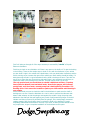
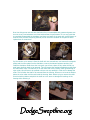
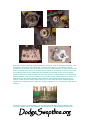
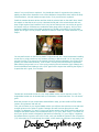
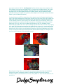
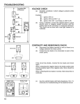
Chrysler Electronic Ignitions
Installing or up grading from a breaker point ignition to an electronic ignition is definitely a
reliability and performance gain all around. The Chrysler Electronic Ignition System is very simple
to install in your Mopar. There are a couple of things to keep in mind if your going to install the
Electronic System: is you will need to maintain a constant voltage in your system, this can be
achieved two ways one is to upgrade to an electronic voltage regulator (which requires some
extra wiring and parts to be installed along with a newer solid state electronic alternator &
regulator) or you can replace your stock point type regulator with a new solid state direct
replacement for your older 1969 & earlier charging system.
I have used this new regulator and it works real well and helps simplify (no wiring or new
alternator) the installation.
You will or should run good 8mm ignition wires, I like and use Taylor Wires, and they work real
well on an electronic system.
You will also want to change the plug gap and bring it out to .040 with the Electronic Ignition, no
special plugs or fancy gadget plugs, just take your stock application Champions and gap them at
.040, along with a new coil. Accel makes coils specifically designed for your Mopar Electronic
System; I would recommend the Accel 140305, which is a 1958-1978 Mopar application.
Now there are two ways to successfully install an Electronic Ignition: One is you can go to the
local bone yard and find a good used distributor, wiring harness, ECU (Electronic Control Unit),
rebuild the distributor and install; Two you can go to your local speed shop and buy a Mopar
Performance conversion kit with all the same parts, brand new you need to complete the install.
Either way depending on your budget it will add a few ponies to your Mopar.
While viewing this document change your zoom level to 200% or better to see the
images better or in more detail.
Here are your basic wiring diagrams to show the wiring of a Chrysler Electronic System.
Here are some pictures showing components and tools needed to successfully install a Chrysler
Electronic System.
First I will take you through all of the steps necessary to successfully “rebuild” a Chrysler
Electronic distributor.
First thing to check on any distributor is if there is any wear on the shaft or if it's just the bushing
in the housing. There are two simple ways to check it. One with the distributor in your vehicle
you can check it right in the vehicle with a dwell meter, with your dwell meter hooked up and the
vehicle running as you increase the rpms of the vehicle your dwell reading should be steady, if it
starts bouncing around it's a good indication that the shaft or bushings are worn. Two with the
cap off try to move the rotor from side to side and if there is any movement you will have to
replace the shaft or the bushing one of the two. The best way to check it is the first.
The only special tools you should have to rebuild a distributor will be a 74 and up
Factory Service Manual, tach and dwell meter, brass feeler gauges, dial indicator,
spring scale, volt/ohm meter, vacuum pump and a bushing driver/burnisher. The
bushing driver is the same tool needed to replace your intermediate shaft bushing in
your engine.
First as mentioned you want to check the shaft in the distributor to make sure the shaft or
bushings are not worn. Place the distributor in a vise in order to perform the side wear test.
Attach a dial indicator so that the plunger rests against the reluctor. Using the spring scale
attached to the shaft pull the scale applying one pound of pull toward the plunger on the dial
indicator and then one pound of pull away from the plunger. If the total plunger movement
reading exceeds .006 you will either have to replace the shaft or the bushings? I would
completely disassemble the distributor one-way or the other. A factory Service Manual will be
very helpful here, to give a complete breakdown of the distributor and its parts.
Over time things wear out and with distributors they are assembled with grease and grease can
turn into a very hard substance over time and decrease the performance. It is a very good idea
to completely disassemble the distributor and clean and wash all the parts with a good cleaner or
solvent. Once you have everything cleaned you can check the condition of the parts to either
replace them or reuse them.
Pry the reluctor up to remove it from the shaft with two screwdrivers, next remove the magnetic
pickup and the lower plate from the distributor, remove the Vacuum advance canister, then
inside the distributor shaft where the rotor goes you will see a piece of felt, under the felt is a
small snap ring that needs to be removed. This will remove the mechanical advancing shaft from
the main shaft. There is a small roll pin on the lower side of the housing, which goes through a
nylon collar, this will have to be pressed or driven out very carefully in order not to damage the
collar. This will allow the shaft to be removed from the housing. Be sure not to loose the washer
above the nylon collar and the seal inside the housing. Note: before trying to remove the shaft
from the housing deburr and polish the shaft as not to score or damage the bushings in the
housing while removing it.
Now that you have completely disassembled your distributor, clean all the parts thoroughly, once
everything is cleaned you can reassemble. There are two bushings in the housing, they are
pressed into the housing, they can be removed with punch and hammer or a press, once the new
ones are installed they will have to be burnished or reamed to fit the shaft, once this is done you
can install the shaft into the housing and pre-lubricate the shaft with a light axle type grease.
Install the mechanical advance weights on the main shaft, do not apply grease to the mechanical
advance weights, a little oil on the slides is fine no grease. Apply a small amount of grease to the
slide buttons on the vacuum advance plate; install the vacuum plate and pickup plate in the
housing. Install the nylon collar, washer and roll pin on the shaft. Check the vacuum advance
canister with a vacuum pump to make sure it holds a vacuum of 15 in. otherwise you will have to
replace it.
To test the pickup in your distributor, you will need your ohmmeter. Place the leads of your
ohmmeter on each wire of the distributor, you should have a reading between 350 and 550
ohms, if not you will have to replace it. You should also check for a ground on the pickup by
placing one lead of the ohmmeter to one of the distributor wires and the other lead to the body
of the distributor, it should read as an open circuit, if not you will have to replace it.
Install the vacuum advance canister and then slide the reluctor back on the shaft. Note: Install
the reluctor so that the arrow is on top. Lubricate the felt pad in the reluctor sleeve with one
drop of light engine oil and install the rotor. Last, but not least you can now set the air gap for
the pickup. Using an .008 brass non-conductive feeler gauge set the air gap to .008, no force
should be needed to remove the feeler gauge and you should not be able to fit a .010 feeler
gauge into the gap if it’s set properly. Now you’re ready to install your rebuilt distributor in your
engine.
You can perform tests on the ECU to check if it’s good as well, but I would recommend installing
a new one vs. using a used one, only because you have no idea how old it is. In any event you
can test from Pin #5 to ground or the housing of the ECU with an ohmmeter, this will test for a
ground, you should have continuity, if not it’s bad. The only other test that can be performed
after checking the ground is on or in the car by removing the coil secondary (high voltage) wire
from the distributor and holding it with a 3/16” gap from the engine then cranking the engine, if
it sparks the unit is good, if not it’s bad.
I would also recommend the use of a new single ballast resistor over a used one as well. The
single ballast resistor can be checked with your ohmmeter, it should read from .5 to 1.8 ohms if
good.
Now that you have all your components and distributor ready, you can install the ECU, ballast
resistor, wiring harness and new coil.
First, you will notice on your original ballast resistor you will have two red wires on one side and
a single red wire on the other for trucks. Passenger cars will have two blue wires on each
terminal. To determine (I-1) and (I-2) turn your ignition switch to the “RUN” position and test for
voltage at the ballast resistor, this will determine the (I-2) or your “RUN” wire(s). The reason for
this is your ignition switch is designed so that while your starting (I-1) your engine, it bypasses
the ballast resistor to give the coil a full 12 volts, once you release the ignition to the run position
(I-2) it then puts the 12 volts through the resistor, which means you have two wires coming from
your ignition switch (I-1 & I-2). See Diagrams The Blue w/Yellow tracer wire coming from the
ECU connector is going to be connected to the (I-2) terminal on the ballast resistor, this is were
you will need the special terminal adapter, which will allow you to connect two female spade
terminals to the one male spade terminal on the ballast resistor. Using this adapter terminal
eliminates cutting your original wiring harness (these adapters can be bought at places like Radio
Shack or your local Auto Parts stores).
You should mount your ECU in a place where it not going to see a lot of engine heat. Mounting
high in the engine compartment is better than mounting it low and in the flow of air through your
engine bay. Once you locate your ECU and mount it, you should run a heavy ground wire from
one of attaching screws to a good ground, this eliminates relying on the mounting screw as the
ground. Next plan the routing of your ECU wiring harness to the ballast resistor (Blue w/Yellow
tracer wire or Pin #1), then to the coil (Black w/Yellow wire or Pin #2), distributor (Brown
w/White & Gray w/White wire or Pin #4 & 5) and tape up the Green wire or Pin #3 it is not going
to be used. The original wire coming from your ballast resistor to your coil + terminal will remain
as is, and the Black w/Yellow from the ECU will go to the – terminal of your new coil. So, all you
should have to do is cut open your original wiring harness to the coil and distributor and re-tape
it with the new wires coming from the ECU harness and the same will apply for running the new
wire from the ECU harness to the new ballast resistor.
Once all you’re wiring is done, you can install your plugs and plug wires. 6cyl and Small Block
V8’s the firing order or distributor rotation is clockwise. Big Block V8’s the firing order or
distributor rotation is counterclockwise. Your 6cyl. Firing Order is 1-5-3-6-2-4 and all V8’s are 1-84-3-6-5-7-2.
Now, the best way I have found to tune a newly installed Electronic Ignition System is by setting
your ignition advance to a “Total” of 34 degrees meaning your vacuum and mechanical advance
combined. In order to do this you should have a timing light with a degree wheel on it; this will
take some fine-tuning of your carb as well. “Total Advance” should be checked with the engine at
2500-2600 rpm’s. If you disconnect your vacuum advance and bring the engine up to an rpm
where it will stop advancing this will give you your total mechanical advance. Once you know
what your total mechanical advance is, then you can adjust your vacuum advance by turning the
adjustment of the canister with a 3/32 allen wrench through the port nipple on the vacuum
canister in or out to increase or decrease the amount of total vacuum advance at 2500-2600
rpm’s. Keep in mind this may require you to retard or advance the distributor timing as well and
depending on your engines camshaft, compression ratio’s, etc. it may require or be able to
handle more or less ignition timing. Once you get a base line established as a general rule with
the least amount of “Total Advance” and maintain a good idle, you can then further fine-tune
even more based on the performance of a road test.
Now your Mopar should be reliably and electronically firing all your cylinders be it 6
or 8.