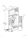
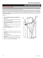
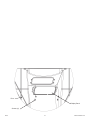
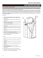
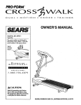
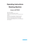
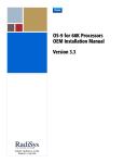
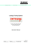
1
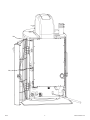
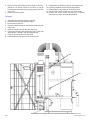
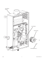
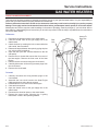
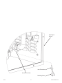
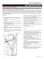
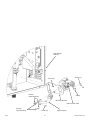
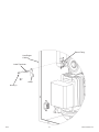
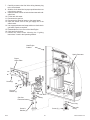
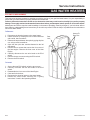
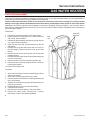
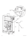
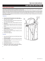
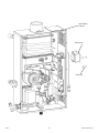
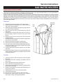
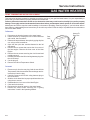
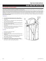
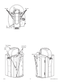
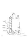
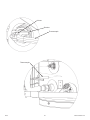
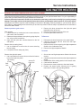
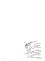
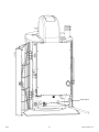
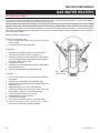
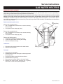
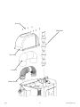
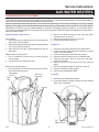
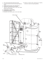
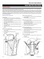
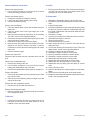
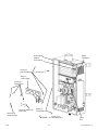
Service Instructions
GAS WATER HEATERS
HEAT ENGINE REPLACEMENT
This instruction has been prepared to acquaint you with the service of your gas-fired water heater. It is your responsibility to
ensure that your water heater is properly installed and maintained.
Failure to follow the instructions in this service instruction sheet may result in serious bodily injury and/or property
damage. Thoroughly read and understand all instructions before you attempt to install, operate or service this heater.
Maintenance and service requires trade knowledge in the areas of plumbing, electricity and gas. If you lack these skills or
have difficulty understanding these instructions you should not proceed. Enlist the help of a qualified service technician to
service this water heater.
3. Remove the flexible elbow from the top of the heat
engine.
Remove panels to gain access:
Door opening
1. Unlock the door by rotating the lock counter-clockwise
with a wide, slot screwdriver.
2. Release the top and bottom door pins by prying the pins
out, using a small screwdriver.
3. Open the door (the door remains fastened to the left
side panel).
Remove the right side panel
1. Use a screwdriver to remove the screw from the bottom,
front of the right side panel.
2. Remove the three screws from the right side panel
towards the rear of the unit.
3. Remove the screw from the top of the unit.
4. Push the panel back and lift out.
Remove the top casing (front)
1. Use a screwdriver to remove the six screws securing
the top casing.
2. Lift up and remove casing top (front).
To Remove:
1. Disconnect the electrical power to the water heater.
2. Close the shutoff valve on the gas supply line to the
water heater.
3. Close the shutoff valves on both the hot-water and coldwater lines.
4. Drain the tank following the instructions in the “Draining
The Tank” section in the Operating Manual.
5. Disconnect the hoses from the heat engine (top is water
outlet and bottom is water inlet).
6. Disconnect the gas line from the heat engine.
7. Carefully disconnect the wire harnesses from the heat
engine.
Remove the flexible venting
1. Unwrap the insulation covering to expose the front elbow
of the venting.
2. Loosen the gear clamps securing the venting.
Top Casing
(Front)
Access To
Door Pins
Door
Lock
Screws
Screws
Screws
Top
Casing (Front)
0610
1
319172-000 Rev. 00
Nut
Nut
0610
2
319172-000 Rev. 00
8. Remove the 4 nuts holding the heat engine to the tank.
(Requires 1/2” wrench, socket or nut-driver.) It may be
necessary to remove part of the venting system to access
some nuts.
9. Remove the heat engine.
9.
10.
11.
12.
13.
Reassemble the flexible venting in the reverse order.
Re-fit the insulation around the exhaust elbows.
Reassemble the top casing in the reverse order.
Reconnect the electrical power to the water heater.
Restart the water heater following the “Lighting
Instructions” found in the Operating Manual.
To Install:
1.
2.
3.
4.
5.
6.
7.
8.
Assemble the new heat engine to the tank.
Reconnect the hoses to the heat engine.
Reconnect the gas line.
Open the shutoff valves on both the hot-water and coldwater lines.
Open the shutoff valve on the gas supply line.
Fill the tank following the instructions in the “Filling The
Water Heater” section in the Operating Manual.
Carefully reconnect the wire harnesses.
Reassemble the side panel in the reverse order.
Nut
Nut
0610
3
319172-000 Rev. 00
0610
4
319172-000 Rev. 00
Service Instructions
GAS WATER HEATERS
CIRCULATION PUMP REPLACEMENT
This instruction has been prepared to acquaint you with the service of your gas-fired water heater. It is your responsibility to
ensure that your water heater is properly installed and maintained.
Failure to follow the instructions in this service instruction sheet may result in serious bodily injury and/or property
damage. Thoroughly read and understand all instructions before you attempt to install, operate or service this heater.
Maintenance and service requires trade knowledge in the areas of plumbing, electricity and gas. If you lack these skills or
have difficulty understanding these instructions you should not proceed. Enlist the help of a qualified service technician to
service this water heater.
7. Secure the Ground Lug with the screw.
8. Carefully reconnect the wiring harness plug to the circuit
board.
9. Slide the circuit board into its proper position and secure
using the two screws.
10. Reassemble the front cover of the Heat Engine.
11. Close and lock the door.
12. Open the shutoff valve on the gas supply line to the
water heater.
13. Reconnect the electrical power to the water heater.
14. Restart the water heater following the “Lighting
Instructions” found in the Operating Manual.
To Remove:
1. Disconnect the electrical power to the water heater.
2. Close the shutoff valves on both the hot-water and coldwater lines.
3. Close the shutoff valve on the gas supply line to the
water heater.
4. Unlock the door by rotating the lock counter-clockwise
with a wide, slot screwdriver.
5. Release the top and bottom door pins by prying the pins
out, using a small screwdriver.
6. Open the door (the door remains fastened to the left
side panel).
7. Remove the ten screws that secure the front cover of
the heat engine. Remove the front cover of the Heat
Engine.
8. Remove the two screws securing the circuit board and
partially extract it.
9. Carefully disconnect the Circulating Pump wiring harness
plug from the circuit board.
10. Drain the tank following the instructions in the “Draining
The Tank” section in the Operating Manual.
11. Disconnect the lower hose from the Water Inlet fitting on
the left hand side of the Heat Engine Cabinet.
12. Remove the two mounting screws for Water Inlet (suction
side) of the pump.
13. Remove the two screws on the discharge side (copper
piping) of the pump.
14. Remove the remaining four Circulating Pump mounting
screws; two located at the bottom of the Heat Engine
Cabinet, and two located at the Water Inlet.
15. Remove the pump.
Access To
Door Pins
Door
Lock
To Install:
1. Assemble the new pump to the Heat Engine Cabinet
using the four screws.
2. Reassemble the copper piping to the pump (discharge
side).
3. Reassemble the Water Inlet fitting to the Heat Engine
Cabinet.
4. Reconnect the lower hose to the Water Inlet fitting.
5. Open the shutoff valves on both the hot-water and coldwater lines.
6. Fill the tank following the instructions in the “Filling The
Water Heater” section in the Operating Manual.
0610
5
319172-000 Rev. 00
Heat Engine
Cabinet
ScrewGround Lug
Circuit Board
Circulation Pump
ScrewsWater Inlet
Copper Piping
ScrewsPump Mounting
0610
Water Inlet Fitting
ScrewsPump Mounting
6
Screws-Pump
Discharge
319172-000 Rev. 00
Service Instructions
GAS WATER HEATERS
BLOWER MOTOR REPLACEMENT
This instruction has been prepared to acquaint you with the service of your gas-fired water heater. It is your responsibility to
ensure that your water heater is properly installed and maintained.
Failure to follow the instructions in this service instruction sheet may result in serious bodily injury and/or property
damage. Thoroughly read and understand all instructions before you attempt to install, operate or service this heater.
Maintenance and service requires trade knowledge in the areas of plumbing, electricity and gas. If you lack these skills or
have difficulty understanding these instructions you should not proceed. Enlist the help of a qualified service technician to
service this water heater.
To Remove:
Access To
Door Pins
1. Disconnect the electrical power to the water heater.
2. Close the shutoff valve on the gas supply line to the
water heater.
3. Unlock the door by rotating the lock counter-clockwise
with a wide, slot screwdriver.
4. Release the top and bottom door pins by prying the pins
out, using a small screwdriver.
5. Open the door (the door remains fastened to the left
side panel).
6. Remove the ten screws that secure the front cover of
the heat engine. Remove the front cover of the Heat
Engine.
7. Remove the two screws securing the circuit board and
partially extract it.
8. Carefully disconnect the Blower Motor wiring harness
plug from the circuit board.
9. Remove the three screws securing the Blower Motor.
10. Remove the Blower Motor.
Door
Lock
To Install:
1. Assemble the new Blower Motor using the three
screws.
2. Carefully reconnect the wiring harness plug to the circuit
board.
3. Slide the circuit board into its proper position and secure
using the two screws.
4. Reassemble the front cover of the Heat Engine.
5. Close and lock the door.
6. Open the shutoff valve on the gas supply line to the
water heater.
7. Reconnect the electrical power to the water heater.
8. Restart the water heater following the “Lighting
Instructions” found in the Operating Manual.
0610
7
319172-000 Rev. 00
Heat Engine
Cabinet
Circuit Board
Blower Motor
Mounting Screw (3)
0610
8
319172-000 Rev. 00
Service Instructions
GAS WATER HEATERS
CIRCUIT BOARD REPLACEMENT
This instruction has been prepared to acquaint you with the service of your gas-fired water heater. It is your responsibility to
ensure that your water heater is properly installed and maintained.
Failure to follow the instructions in this service instruction sheet may result in serious bodily injury and/or property
damage. Thoroughly read and understand all instructions before you attempt to install, operate or service this heater.
Maintenance and service requires trade knowledge in the areas of plumbing, electricity and gas. If you lack these skills or
have difficulty understanding these instructions you should not proceed. Enlist the help of a qualified service technician to
service this water heater.
To Remove:
Access To
Door Pins
1. Disconnect the electrical power to the water heater.
2. Close the shutoff valve on the gas supply line to the
water heater.
3. Unlock the door by rotating the lock counter-clockwise
with a wide, slot screwdriver.
4. Release the top and bottom door pins by prying the pins
out, using a small screwdriver.
5. Open the door (the door remains fastened to the left
side panel).
6. Remove the ten screws that secure the front cover of
the heat engine. Remove the front cover of the Heat
Engine.
7. Remove the two screws securing the circuit board.
8. Carefully disconnect all the wiring harness plugs from
the circuit board.
9. Remove the circuit board.
Door
Lock
To Install:
1. Carefully reconnect the wiring harness plugs to the
circuit board.
2. Assemble the new circuit board to the Heat Engine
Cabinet and secure using the two screws.
3. Reassemble the front cover of the Heat Engine.
4. Close and lock the door.
5. Open the shutoff valve on the gas supply line to the
water heater.
6. Reconnect the electrical power to the water heater.
7. Restart the water heater following the “Lighting
Instructions” found in the Operating Manual.
0610
9
319172-000 Rev. 00
Heat Engine
Cabinet
Circuit Board
Mounting Screw (2)
0610
10
319172-000 Rev. 00
Service Instructions
GAS WATER HEATERS
DISPLAY PANEL REPLACEMENT
This instruction has been prepared to acquaint you with the service of your gas-fired water heater. It is your responsibility to
ensure that your water heater is properly installed and maintained.
Failure to follow the instructions in this service instruction sheet may result in serious bodily injury and/or property
damage. Thoroughly read and understand all instructions before you attempt to install, operate or service this heater.
Maintenance and service requires trade knowledge in the areas of plumbing, electricity and gas. If you lack these skills or
have difficulty understanding these instructions you should not proceed. Enlist the help of a qualified service technician to
service this water heater.
To Remove:
Access To
Door Pins
1. Disconnect the electrical power to the water heater.
2. Close the shutoff valve on the gas supply line to the
water heater.
3. Unlock the door by rotating the lock counter-clockwise
with a wide, slot screwdriver.
4. Release the top and bottom door pins by prying the pins
out, using a small screwdriver.
5. Open the door (the door remains fastened to the left
side panel).
6. Carefully disconnect all the wiring harness plugs from
the Display Panel.
7. Remove the four screws securing the Display Panel.
8. Remove the Display Panel.
Door
Lock
To Install:
1. Assemble the new Display Panel to the door using the
four screws.
2. Carefully reconnect the wiring harness plugs to the
Display Panel.
3. Close and lock the door.
4. Open the shutoff valve on the gas supply line to the
water heater.
5. Reconnect the electrical power to the water heater.
6. Restart the water heater following the “Lighting
Instructions” found in the Operating Manual.
0610
11
319172-000 Rev. 00
Door
Display Panel
Screws (4)
0610
12
319172-000 Rev. 00
Service Instructions
GAS WATER HEATERS
INLET THERMISTOR REPLACEMENT
This instruction has been prepared to acquaint you with the service of your gas-fired water heater. It is your responsibility to
ensure that your water heater is properly installed and maintained.
Failure to follow the instructions in this service instruction sheet may result in serious bodily injury and/or property
damage. Thoroughly read and understand all instructions before you attempt to install, operate or service this heater.
Maintenance and service requires trade knowledge in the areas of plumbing, electricity and gas. If you lack these skills or
have difficulty understanding these instructions you should not proceed. Enlist the help of a qualified service technician to
service this water heater.
To Remove:
Access To
Door Pins
1. Disconnect the electrical power to the water heater.
2. Close the shutoff valve on the gas supply line to the
water heater.
3. Close the shutoff valves on both the hot-water and coldwater lines.
4. Unlock the door by rotating the lock counter-clockwise
with a wide, slot screwdriver.
5. Release the top and bottom door pins by prying the pins
out, using a small screwdriver.
6. Open the door (the door remains fastened to the left
side panel).
7. Remove the ten screws that secure the front cover of
the heat engine. Remove the front cover of the Heat
Engine.
8. Carefully disconnect the wire harness plug leading to
thermistor.
9. Drain the tank following the instructions in the “Draining
The Tank” section in the Operating Manual.
10. Remove the retaining screw for the inlet thermistor
“(using an offset right angle Phillips screwdriver)”.
11. Remove the thermistor.
Door
Lock
To Install:
1. Secure the new thermistor in place with the retaining
screw.
2. Open the shutoff valves on both the hot-water and coldwater lines.
3. Fill the tank with water. Check for leaks and repair as
required.
4. Carefully reconnect the wiring harness plug to the
thermistor.
5. Reassemble the front cover of the Heat Engine.
6. Close and lock the door.
7. Open the shutoff valve on the gas supply line to the
water heater.
8. Reconnect the electrical power to the water heater.
9. Restart the water heater following the “Lighting
Instructions” found in the Operating Manual.
0610
13
319172-000 Rev. 00
Heat Engine
Cabinet
Inlet Thermistor
Internal Flow Valve
Retaining Screw
0610
14
319172-000 Rev. 00
Service Instructions
GAS WATER HEATERS
INTERNAL FLOW VALVE REPLACEMENT
This instruction has been prepared to acquaint you with the service of your gas-fired water heater. It is your responsibility to
ensure that your water heater is properly installed and maintained.
Failure to follow the instructions in this service instruction sheet may result in serious bodily injury and/or property
damage. Thoroughly read and understand all instructions before you attempt to install, operate or service this heater.
Maintenance and service requires trade knowledge in the areas of plumbing, electricity and gas. If you lack these skills or
have difficulty understanding these instructions you should not proceed. Enlist the help of a qualified service technician to
service this water heater.
9. Drain the tank following the instructions in the “Draining
The Tank” section in the Operating Manual.
10. Remove the two screws that fasten the copper piping to
the Circulation Pump (discharge side).
11. Remove the two screws from the flange on the outlet
side of the flow valve and remove the clamp.
12. Remove the two screws fastening the flow valve mounting
bracket to the Heat Engine Cabinet.
13. Remove the two screws fastening the copper piping to
the flow valve mounting bracket.
14. Remove the two screws fastening the flow valve to the
mounting bracket.
15. Remove the Internal Flow Valve.
To Remove:
1. Disconnect the electrical power to the water heater.
2. Close the shutoff valve on the gas supply line to the
water heater.
3. Close the shutoff valves on both the hot-water and coldwater lines.
4. Unlock the door by rotating the lock counter-clockwise
with a wide, slot screwdriver.
5. Release the top and bottom door pins by prying the pins
out, using a small screwdriver.
6. Open the door (the door remains fastened to the left
side panel).
7. Remove the ten screws that secure the front cover of
the heat engine. Remove the front cover of the Heat
Engine.
8. Carefully disconnect the three wire harness plugs leading
to flow valve. Two are for Flow Valve control, one is for
the Inlet Thermistor.
To Install:
1. Secure the new Internal Flow Valve to the mounting
bracket with the two flow valve mounting screws.
2. Secure the copper piping to the flow valve mounting
bracket using the two copper piping mounting screws.
3. Secure the mounting bracket with two screws.
4. Secure the piping for the outlet side of the flow valve with
the clamp and two screws.
5. Secure the copper piping to the Circulation Pump
(discharge side) with two screws.
6. Carefully reconnect the three wire harness plugs.
7. Open the shutoff valves on both the hot-water and coldwater lines.
8. Fill the tank following the instructions in the “Filling The
Water Heater” section in the Operating Manual.
9. Reassemble the front cover of the Heat Engine.
10. Close and lock the door.
11. Open the shutoff valve on the gas supply line to the
water heater.
12. Reconnect the electrical power to the water heater.
13. Restart the water heater following the “Lighting
Instructions” found in the Operating Manual.
Access To
Door Pins
Door
Lock
0610
15
319172-000 Rev. 00
Heat Engine
Cabinet
Screw (2)
Screw (2)
ScrewsValve Mounting
Clamp
Mounting Bracket
Internal Flow Valve
ScrewsPipe Mounting
0610
Screw (2)
16
Copper Piping
319172-000 Rev. 00
Service Instructions
GAS WATER HEATERS
OUTLET THERMISTOR REPLACEMENT
This instruction has been prepared to acquaint you with the service of your gas-fired water heater. It is your responsibility to
ensure that your water heater is properly installed and maintained.
Failure to follow the instructions in this service instruction sheet may result in serious bodily injury and/or property
damage. Thoroughly read and understand all instructions before you attempt to install, operate or service this heater.
Maintenance and service requires trade knowledge in the areas of plumbing, electricity and gas. If you lack these skills or
have difficulty understanding these instructions you should not proceed. Enlist the help of a qualified service technician to
service this water heater.
To Remove:
Access To
Door Pins
1. Disconnect the electrical power to the water heater.
2. Close the shutoff valve on the gas supply line to the
water heater.
3. Close the shutoff valves on both the hot-water and coldwater lines.
4. Unlock the door by rotating the lock counter-clockwise
with a wide, slot screwdriver.
5. Release the top and bottom door pins by prying the pins
out, using a small screwdriver.
6. Open the door (the door remains fastened to the left
side panel).
7. Remove the ten screws that secure the front cover of
the heat engine. Remove the front cover of the Heat
Engine.
8. Carefully disconnect the wire harness plug leading to
thermistor.
9. Drain the tank following the instructions in the “Draining
The Tank” section in the Operating Manual.
10. Remove the two screws from the flange on the return
fitting and remove the clamp.
11. Remove the thermistor.
Door
Lock
To Install:
1. Secure the new thermistor in place with the clamp and
two screws.
2. Open the shutoff valves on both the hot-water and coldwater lines.
3. Fill the tank with water. Check for leaks and repair as
required.
4. Carefully reconnect the wiring harness plug to the
thermistor.
5. Reassemble the front cover of the Heat Engine.
6. Close and lock the door.
7. Open the shutoff valve on the gas supply line to the
water heater.
8. Reconnect the electrical power to the water heater.
9. Restart the water heater following the “Lighting
Instructions” found in the Operating Manual.
0610
17
319172-000 Rev. 00
Return Fitting
Heat Engine
Cabinet
Outlet Thermistor
Clamp
Screw (2)
0610
18
319172-000 Rev. 00
Service Instructions
GAS WATER HEATERS
GAS VALVE REPLACEMENT
This instruction has been prepared to acquaint you with the service of your gas-fired water heater. It is your responsibility to
ensure that your water heater is properly installed and maintained.
Failure to follow the instructions in this service instruction sheet may result in serious bodily injury and/or property
damage. Thoroughly read and understand all instructions before you attempt to install, operate or service this heater.
Maintenance and service requires trade knowledge in the areas of plumbing, electricity and gas. If you lack these skills or
have difficulty understanding these instructions you should not proceed. Enlist the help of a qualified service technician to
service this water heater.
To Remove:
To Install:
1. Disconnect the electrical power to the water heater.
2. Close the shutoff valve on the gas supply line to the
water heater.
3. Close the shutoff valves on both the hot-water and coldwater lines.
4. Unlock the door by rotating the lock counter-clockwise
with a wide, slot screwdriver.
5. Release the top and bottom door pins by prying the pins
out, using a small screwdriver.
6. Open the door (the door remains fastened to the left
side panel).
7. Remove the ten screws that secure the front cover of
the heat engine. Remove the front cover of the Heat
Engine.
8. Remove the two screws securing the circuit board and
partially extract it.
9. Carefully disconnect the Gas Valve wiring harness plug
from the circuit board.
10. Disconnect the gas line from the heat engine.
11. Remove the two screws that secure the Gas Inlet
Fitting.
12. Remove the four screws that secure the Burner Orifice
Plate. One of these screws also secures the Spark
Generator.
13. Pull the Gas Valve Assembly away from the heat
engine.
14. Carefully disconnect the wire harness from the Gas
Valve Assembly.
15. Remove the five screws and washers securing the Burner
Orifice Plate to the Gas Valve.
16. Remove the four screws and washers that secure the
Gas Line Extension to the Gas Valve.
17. Remove the Gas Valve.
1. Fasten the Gas Line Extension to the new Gas Valve
with the four screws and washers. Ensure the O-ring is
undamaged and properly positioned.
2. Secure the Burner Orifice Plate to the Gas Valve with
five screws and washers.
3. Carefully reconnect the wire harness to the Gas Valve
Assembly (green wire pair to the lower right solenoid,
yellow & black pair wire to the lower left solenoid, black
& white pair to the top right side solenoid and black &
brown pair to the top left side solenoid).
4. Install the Gas Valve Assembly into the heat engine,
ensuring the Assembly is seated properly between the
Orifice Plate and the heat engine.
5. Secure the Orifice Plate with four screws. Ensure the
Spark Generator is properly secured.
6. Secure the Gas Inlet Fitting with two screws. Ensure the
O-ring is undamaged and properly positioned.
0610
Access To
Door Pins
Door
Lock
19
319172-000 Rev. 00
7. Carefully reconnect the Gas Valve wiring harness plug
to the circuit board.
8. Slide the circuit board into its proper position and secure
using the two screws.
9. Open the shutoff valves on both the hot-water and coldwater lines.
10. Fill the tank with water.
11. Reconnect the gas line.
12. Reconnect the electrical power to the water heater.
13. Open the shutoff valve on the gas supply line to the
water heater.
14. Use a approved water and soap solution to check the for
gas leaks. Repair as required.
15. Reassemble the front cover of the Heat Engine.
16. Close and lock the door.
17. Restart the water heater following the “Lighting
Instructions” found in the Operating Manual.
Heat Engine
Cabinet
Spark Generator
Burner
Orifice Plate
Screw (4)
Screw &
Washer (5)
Gas Valve
Gas Line
Extension
O-ring
O-ring
Screw (2)
Screw &
Washer (4)
0610
20
Gas Inlet
Fitting
319172-000 Rev. 00
Service Instructions
GAS WATER HEATERS
ECO SWITCH REPLACEMENT
This instruction has been prepared to acquaint you with the service of your gas-fired water heater. It is your responsibility to
ensure that your water heater is properly installed and maintained.
Failure to follow the instructions in this service instruction sheet may result in serious bodily injury and/or property
damage. Thoroughly read and understand all instructions before you attempt to install, operate or service this heater.
Maintenance and service requires trade knowledge in the areas of plumbing, electricity and gas. If you lack these skills or
have difficulty understanding these instructions you should not proceed. Enlist the help of a qualified service technician to
service this water heater.
To Remove:
Access To
Door Pins
1. Disconnect the electrical power to the water heater.
2. Unlock the door by rotating the lock counter-clockwise
with a wide, slot screwdriver.
3. Release the top and bottom door pins by prying the pins
out, using a small screwdriver.
4. Open the door (the door remains fastened to the left
side panel).
5. Remove the ten screws that secure the front cover of
the heat engine. Remove the front cover of the Heat
Engine.
6. Carefully disconnect the two wire leads to the ECO
switch.
7. Remove the two screws securing the ECO switch.
8. Remove the ECO switch.
Door
Lock
To Install:
1. Secure the new ECO switch using the two screws.
2. Carefully reconnect the two wire leads to the ECO
switch.
3. Reassemble the front cover of the Heat Engine.
4. Close and lock the door.
5. Reconnect the electrical power to the water heater.
6. Restart the water heater following the “Lighting
Instructions” found in the Operating Manual.
0610
21
319172-000 Rev. 00
Heat Engine
Cabinet
Screw (2)
ECO
Transformer
0610
22
319172-000 Rev. 00
Service Instructions
GAS WATER HEATERS
POWER CORD REPLACEMENT
This instruction has been prepared to acquaint you with the service of your gas-fired water heater. It is your responsibility to
ensure that your water heater is properly installed and maintained.
Failure to follow the instructions in this service instruction sheet may result in serious bodily injury and/or property
damage. Thoroughly read and understand all instructions before you attempt to install, operate or service this heater.
Maintenance and service requires trade knowledge in the areas of plumbing, electricity and gas. If you lack these skills or
have difficulty understanding these instructions you should not proceed. Enlist the help of a qualified service technician to
service this water heater.
To Remove:
Access To
Door Pins
1. Disconnect the electrical power to the water heater.
2. Unlock the door by rotating the lock counter-clockwise
with a wide, slot screwdriver.
3. Release the top and bottom door pins by prying the pins
out, using a small screwdriver.
4. Open the door (the door remains fastened to the left
side panel).
5. Remove the ten screws that secure the front cover of
the heat engine. Remove the front cover of the Heat
Engine.
6. Remove the two screws securing the circuit board and
partially extract it.
7. Carefully disconnect the Power Cord wiring harness plug
from the circuit board.
8. Remove the two screws securing the Ground Lugs.
9. Remove the two screws securing the Power Cord to the
Heat Engine Cabinet.
10. Remove the Power Cord.
Door
Lock
To Install:
1. Secure the new Power Cord to the Heat Engine Cabinet
with the two screws.
2. Secure the Ground Lugs with the two screws.
3. Carefully reconnect the Power Cord wiring harness plug
to the circuit board.
4. Slide the circuit board into its proper position and secure
using the two screws.
5. Reassemble the front cover of the Heat Engine.
6. Close and lock the door.
7. Reconnect the electrical power to the water heater.
8. Restart the water heater following the “Lighting
Instructions” found in the Operating Manual.
9.
0610
23
319172-000 Rev. 00
Screw-Ground
Lug (2)
Heat Engine
Cabinet
Screw (2)
Power Cord
0610
24
319172-000 Rev. 00
Service Instructions
GAS WATER HEATERS
TRANSFORMER REPLACEMENT
This instruction has been prepared to acquaint you with the service of your gas-fired water heater. It is your responsibility to
ensure that your water heater is properly installed and maintained.
Failure to follow the instructions in this service instruction sheet may result in serious bodily injury and/or property
damage. Thoroughly read and understand all instructions before you attempt to install, operate or service this heater.
Maintenance and service requires trade knowledge in the areas of plumbing, electricity and gas. If you lack these skills or
have difficulty understanding these instructions you should not proceed. Enlist the help of a qualified service technician to
service this water heater.
To Remove:
Access To
Door Pins
1. Disconnect the electrical power to the water heater.
2. Unlock the door by rotating the lock counter-clockwise
with a wide, slot screwdriver.
3. Release the top and bottom door pins by prying the pins
out, using a small screwdriver.
4. Open the door (the door remains fastened to the left
side panel).
5. Remove the ten screws that secure the front cover of
the heat engine. Remove the front cover of the Heat
Engine.
6. Remove the two screws securing the circuit board and
partially extract it.
7. Carefully disconnect the Transformer wiring harness
plugs from the circuit board.
8. Remove the four screws securing the Transformer to the
Heat Engine Cabinet.
9. Remove the Transformer.
Door
Lock
To Install:
1. Secure the new Transformer to the Heat Engine Cabinet
with the four screws.
2. Carefully reconnect the Transformer wiring harness plugs
to the circuit board.
3. Slide the circuit board into its proper position and secure
using the two screws.
4. Reassemble the front cover of the Heat Engine.
5. Close and lock the door.
6. Reconnect the electrical power to the water heater.
7. Restart the water heater following the “Lighting
Instructions” found in the Operating Manual.
8.
0610
25
319172-000 Rev. 00
Heat Engine
Cabinet
Transformer
Screw (4)
0610
26
319172-000 Rev. 00
Service Instructions
GAS WATER HEATERS
FLAME ROD REPLACEMENT
This instruction has been prepared to acquaint you with the service of your gas-fired water heater. It is your responsibility to
ensure that your water heater is properly installed and maintained.
Failure to follow the instructions in this service instruction sheet may result in serious bodily injury and/or property
damage. Thoroughly read and understand all instructions before you attempt to install, operate or service this heater.
Maintenance and service requires trade knowledge in the areas of plumbing, electricity and gas. If you lack these skills or
have difficulty understanding these instructions you should not proceed. Enlist the help of a qualified service technician to
service this water heater.
To Remove:
Access To
Door Pins
1. Disconnect the electrical power to the water heater.
2. Unlock the door by rotating the lock counter-clockwise
with a wide, slot screwdriver.
3. Release the top and bottom door pins by prying the pins
out, using a small screwdriver.
4. Open the door (the door remains fastened to the left
side panel).
5. Remove the ten screws that secure the front cover of
the heat engine. Remove the front cover of the Heat
Engine.
6. Carefully disconnect the wire leading to the Flame
Rod.
7. Remove the two screws securing the Flame Rod.
8. Remove the Flame Rod and Gasket. Ensure old gasket
is completely removed and no material remains.
Door
Lock
To Install:
1. Secure the new Flame Rod and Gasket with the two
screws.
2. Carefully reconnect the wire leading to the Flame Rod.
3. Reassemble the front cover of the Heat Engine.
4. Close and lock the door.
5. Reconnect the electrical power to the water heater.
6. Restart the water heater following the “Lighting
Instructions” found in the Operating Manual.
0610
27
319172-000 Rev. 00
Heat Engine
Cabinet
Gasket
Flame Rod
Screw (2)
0610
28
319172-000 Rev. 00
Service Instructions
GAS WATER HEATERS
SPARK GENERATOR REPLACEMENT
This instruction has been prepared to acquaint you with the service of your gas-fired water heater. It is your responsibility to
ensure that your water heater is properly installed and maintained.
Failure to follow the instructions in this service instruction sheet may result in serious bodily injury and/or property
damage. Thoroughly read and understand all instructions before you attempt to install, operate or service this heater.
Maintenance and service requires trade knowledge in the areas of plumbing, electricity and gas. If you lack these skills or
have difficulty understanding these instructions you should not proceed. Enlist the help of a qualified service technician to
service this water heater.
To Remove:
Access To
Door Pins
1. Disconnect the electrical power to the water heater.
2. Unlock the door by rotating the lock counter-clockwise
with a wide, slot screwdriver.
3. Release the top and bottom door pins by prying the pins
out, using a small screwdriver.
4. Open the door (the door remains fastened to the left
side panel).
5. Remove the ten screws that secure the front cover of
the heat engine. Remove the front cover of the Heat
Engine.
6. Remove the two screws securing the circuit board and
partially extract it.
7. Carefully disconnect the Spark Generator wiring harness
plug from the circuit board.
8. Remove the screw securing the Ground Lugs.
9. Remove the screw securing the Spark Generator.
10. Remove the two screws securing the Electrode assembly.
It may be necessary to remove the Power Cord to gain
access to the two screws.
11. Carefully disconnect the wire harness from the Spark
Generator.
12. Remove the Spark Generator, Electrode assembly and
Gasket. Ensure old gasket is completely removed and
no material remains.
Door
Lock
To Install:
1. Carefully reconnect the wire harness to the new Spark
Generator.
2. Secure the Electrode assembly and Gasket with the
two screws.
3. Secure the Spark Generator with the screw.
4. Secure the Ground Lugs with the screw.
5. Carefully reconnect the Spark Generator wiring harness
plug to the circuit board.
6. Slide the circuit board into its proper position and secure
using the two screws.
7. Reassemble the front cover of the Heat Engine.
8. Close and lock the door.
9. Reconnect the electrical power to the water heater.
10. Restart the water heater following the “Lighting
Instructions” found in the Operating Manual.
0610
29
319172-000 Rev. 00
Screw-Ground
Lug
Heat Engine
Cabinet
Gasket
Electrode
Screw (2)
Screw
Spark
Generator
0610
30
319172-000 Rev. 00
Service Instructions
GAS WATER HEATERS
HILIMIT TEMPERATURE SWITCH REPLACEMENT
This instruction has been prepared to acquaint you with the service of your gas-fired water heater. It is your responsibility to
ensure that your water heater is properly installed and maintained.
Failure to follow the instructions in this service instruction sheet may result in serious bodily injury and/or property
damage. Thoroughly read and understand all instructions before you attempt to install, operate or service this heater.
Maintenance and service requires trade knowledge in the areas of plumbing, electricity and gas. If you lack these skills or
have difficulty understanding these instructions you should not proceed. Enlist the help of a qualified service technician to
service this water heater.
To Remove:
Access To
Door Pins
1. Disconnect the electrical power to the water heater.
2. Unlock the door by rotating the lock counter-clockwise
with a wide, slot screwdriver.
3. Release the top and bottom door pins by prying the pins
out, using a small screwdriver.
4. Open the door (the door remains fastened to the left
side panel).
5. Remove the ten screws that secure the front cover of
the heat engine. Remove the front cover of the Heat
Engine.
6. Remove the two screws securing the circuit board and
partially extract it.
7. Carefully disconnect the HiLimit wiring harness plug from
the circuit board.
8. Cut the plug off.
9. Remove the HiLimit Temperature Switch.
Door
Lock
To Install:
1. Extract one pin from the new plug, feed the new HiLimit
Temperature Switch around the heat exchanger and reinsert the pin into the plug.
2. Carefully reconnect the HiLimit wiring harness plug to
the circuit board.
3. Slide the circuit board into its proper position and secure
using the two screws.
4. Reassemble the front cover of the Heat Engine.
5. Close and lock the door.
6. Reconnect the electrical power to the water heater.
7. Restart the water heater following the “Lighting
Instructions” found in the Operating Manual.
0610
31
319172-000 Rev. 00
HiLimit Temperature
Switch
Heat
Exchanger
Heat Engine
Cabinet
0610
32
319172-000 Rev. 00
Service Instructions
GAS WATER HEATERS
INLET WATER FILTER REPLACEMENT
This instruction has been prepared to acquaint you with the service of your gas-fired water heater. It is your responsibility to
ensure that your water heater is properly installed and maintained.
Failure to follow the instructions in this service instruction sheet may result in serious bodily injury and/or property
damage. Thoroughly read and understand all instructions before you attempt to install, operate or service this heater.
Maintenance and service requires trade knowledge in the areas of plumbing, electricity and gas. If you lack these skills or
have difficulty understanding these instructions you should not proceed. Enlist the help of a qualified service technician to
service this water heater.
To Remove:
Access To
Door Pins
1. Disconnect the electrical power to the water heater.
2. Close the shutoff valves on both the hot-water and coldwater lines.
3. Unlock the door by rotating the lock counter-clockwise
with a wide, slot screwdriver.
4. Release the top and bottom door pins by prying the pins
out, using a small screwdriver.
5. Open the door (the door remains fastened to the left
side panel).
6. Drain the tank following the instructions in the “Draining
The Tank” section in the Operating Manual.
7. Unscrew the Water Inlet Filter.
Door
Lock
To Install:
1. Install the new Water Inlet Filter.
2. Close the drain valve.
3. Open the shutoff valves on both the hot-water and coldwater lines.
4. Fill the tank following the instructions in the “Filling The
Water Heater” section in the Operating Manual.
5. Close and lock the door.
6. Reconnect the electrical power to the water heater.
7. Restart the water heater following the “Lighting
Instructions” found in the Operating Manual.
0610
33
319172-000 Rev. 00
Heat Engine
Cabinet
Water Inlet Filter
Water Inlet Fitting
0610
34
319172-000 Rev. 00
Service Instructions
GAS WATER HEATERS
HOSE (HEAT ENGINE TO STORAGE TANK) REPLACEMENT
This instruction has been prepared to acquaint you with the service of your gas-fired water heater. It is your responsibility to
ensure that your water heater is properly installed and maintained.
Failure to follow the instructions in this service instruction sheet may result in serious bodily injury and/or property
damage. Thoroughly read and understand all instructions before you attempt to install, operate or service this heater.
Maintenance and service requires trade knowledge in the areas of plumbing, electricity and gas. If you lack these skills or
have difficulty understanding these instructions you should not proceed. Enlist the help of a qualified service technician to
service this water heater.
Remove panels to gain access:
To Remove:
1. Close the shutoff valves on both the hot-water and coldRemove Door
water lines.
2. Drain the tank following the instructions in the “Draining
1. Disconnect the electrical power to the water heater.
2. Unlock the door by rotating the lock counter-clockwise
The Tank” section in the Operating Manual.
3. Unscrew the fitting at both ends of the hose assembly(s).
with a wide, slot screwdriver.
3. Release the top and bottom door pins by prying the pins
The upper hose is the (hot) water outlet from the heat
out, using a small screwdriver.
engine. The lower hose is the (cold) water inlet to the
4. Open the door (the door remains fastened to the left
heat engine.
4. Remove the hose assembly(s).
side panel).
5. Carefully disconnect all the wiring harness plugs from
the Display Panel.
To Install:
6. Carefully remove the door hinge pins from their retaining
fingers.
1. Install the new hose assembly(s).
2. Tighten the fitting at both ends of the hose
Remove the top casing (front)
assembly(s).
1. Use a screwdriver to remove the six screws securing
3. Close the drain valve.
the top casing.
4. Open the shutoff valves on both the hot-water and cold2. Lift up and remove casing top (front).
water lines.
5. Fill the tank following the instructions in the “Filling The
Remove the left side panel
Water Heater” section in the Operating Manual.
1. Use a screwdriver to remove the screw from the bottom,
6. Check for leaks and repair as required.
front of the left side panel.
7. Reassemble the side panel in the reverse order.
2. Remove the three screws from the left side panel towards
8. Reassemble the door in the reverse order.
the rear of the unit.
9. Carefully reconnect the wiring harness plugs to the
3. Remove the screw from the top of the unit.
Display Panel.
4. Push the panel back and lift out.
10. Reassemble the top casing in the reverse order.
11. Reconnect the electrical power to the water heater.
12. Restart the water heater following the “Lighting
Instructions” found in the Operating Manual.
0610
35
319172-000 Rev. 00
Screws
Screws
Top
Casing (Front)
Top Casing
(Front)
Access To
Door Pins
Door
Lock
Screws
0610
36
319172-000 Rev. 00
Upper Hose
Assembly (Hot)
Heat Engine
Outlet Fitting
Heat Engine
Inlet Fitting
Lower Hose
Assembly (Cold)
Drain Valve
0610
37
319172-000 Rev. 00
0610
38
319172-000 Rev. 00
Service Instructions
GAS WATER HEATERS
TANK THERMISTOR REPLACEMENT
This instruction has been prepared to acquaint you with the service of your gas-fired water heater. It is your responsibility to
ensure that your water heater is properly installed and maintained.
Failure to follow the instructions in this service instruction sheet may result in serious bodily injury and/or property
damage. Thoroughly read and understand all instructions before you attempt to install, operate or service this heater.
Maintenance and service requires trade knowledge in the areas of plumbing, electricity and gas. If you lack these skills or
have difficulty understanding these instructions you should not proceed. Enlist the help of a qualified service technician to
service this water heater.
To Remove:
Access To
Door Pins
1. Disconnect the electrical power to the water heater.
2. Unlock the door by rotating the lock counter-clockwise
with a wide, slot screwdriver.
3. Release the top and bottom door pins by prying the pins
out, using a small screwdriver.
4. Open the door (the door remains fastened to the left
side panel).
5. Carefully disconnect the Tank Thermistor wiring harness
plug from the Display Panel located on the door.
6. Carefully disconnect the Tank Thermistor wiring harness
plug from the Heat Engine Cabinet.
7. Loosen the screw on the Tank Thermistor bracket and
remove the bracket.
8. Remove the Tank Thermistor.
Door
Lock
To Install:
1. Install the new Tank Thermistor.
2. Reinstall the Tank Thermistor bracket around the
thermistor and tighten the screw.
3. Carefully reconnect the Tank Thermistor wiring harness
plug to the Heat Engine Cabinet.
4. Carefully reconnect the Tank Thermistor wiring harness
plug to the Display Panel.
5. Close and lock the door.
6. Reconnect the electrical power to the water heater.
7. Restart the water heater following the “Lighting
Instructions” found in the Operating Manual.
0610
39
319172-000 Rev. 00
Screw
Bracket
Thermocouple
Thermocouple
0610
40
319172-000 Rev. 00
Service Instructions
GAS WATER HEATERS
EXHAUST VENT HIGH-TEMPERATURE SWITCH REPLACEMENT
This instruction has been prepared to acquaint you with the service of your gas-fired water heater. It is your responsibility to
ensure that your water heater is properly installed and maintained.
Failure to follow the instructions in this service instruction sheet may result in serious bodily injury and/or property
damage. Thoroughly read and understand all instructions before you attempt to install, operate or service this heater.
Maintenance and service requires trade knowledge in the areas of plumbing, electricity and gas. If you lack these skills or
have difficulty understanding these instructions you should not proceed. Enlist the help of a qualified service technician to
service this water heater.
2. Remove the three screws from the right side panel
towards the rear of the unit.
3. Remove the screw from the top of the unit.
4. Push the panel back and lift out.
Remove panels to gain access:
Door opening
1. Unlock the door by rotating the lock counter-clockwise
with a wide, slot screwdriver.
2. Release the top and bottom door pins by prying the pins
out, using a small screwdriver.
3. Open the door (the door remains fastened to the left
side panel).
To Remove:
1. Disconnect the electrical power to the water heater.
2. Carefully disconnect the two wires from the Hightemperature Switch.
3. Remove the two screws securing the High-temperature
Switch to the Condensate Trap.
4. Remove the High-temperature Switch.
Remove the top casing (front)
1. Use a screwdriver to remove the six screws securing
the top casing.
2. Lift up and remove casing top (front).
To Install:
1. Secure the new High-temperature Switch with the two
screws.
2. Carefully reconnect the two wires to the High-temperature
Switch.
3. Reassemble all the casing panels in the reverse order.
4. Close and lock the door.
5. Reconnect the electrical power to the water heater.
6. Restart the water heater following the “Lighting
Instructions” found in the Operating Manual.
Remove the right side panel
1. Use a screwdriver to remove the screw from the bottom,
front of the right side panel.
Top Casing
(Front)
Access To
Door Pins
Door
Lock
Screws
Screws
Screws
Top
Casing (Front)
0610
41
319172-000 Rev. 00
VENTING
EXHAUST
ELBOW
BARBED FITTING
HIGH
TEMPERATURE
SWITCH
DRAIN PAN - ROUTE
TO SUITABLE DRAIN
CONDENSATE
TRAP
CONDENSATE TUBE SLOPE TO SUITABLE DRAIN
NOTE: THE CONDENSATE TUBE
MUST BE BELOW EXHAUST ELBOW.
0610
42
319172-000 Rev. 00
Service Instructions
GAS WATER HEATERS
DRAIN VALVE REPLACEMENT
This instruction has been prepared to acquaint you with the service of your gas-fired water heater. It is your responsibility to
ensure that your water heater is properly installed and maintained.
Failure to follow the instructions in this service instruction sheet may result in serious bodily injury and/or property
damage. Thoroughly read and understand all instructions before you attempt to install, operate or service this heater.
Maintenance and service requires trade knowledge in the areas of plumbing, electricity and gas. If you lack these skills or
have difficulty understanding these instructions you should not proceed. Enlist the help of a qualified service technician to
service this water heater.
To Remove:
Access To
Door Pins
1. Disconnect the electrical power to the water heater.
2. Unlock the door by rotating the lock counter-clockwise
with a wide, slot screwdriver.
3. Release the top and bottom door pins by prying the pins
out, using a small screwdriver.
4. Open the door (the door remains fastened to the left
side panel).
5. Close the shutoff valves on both the hot-water and coldwater lines.
6. Drain the tank following the instructions in the “Draining
The Tank” section in the Operating Manual.
7. Remove the Drain Valve.
Door
Lock
To Install:
1. Use only Teflon tape or an approved pipe sealant on
the threads.
2. Install the new Drain Valve.
3. Open the shutoff valves on both the hot-water and coldwater lines.
4. Fill the tank following the instructions in the “Filling The
Water Heater” section in the Operating Manual.
5. Check for leaks and repair as required.
6. Close and lock the door.
7. Reconnect the electrical power to the water heater.
8. Restart the water heater following the “Lighting
Instructions” found in the Operating Manual.
0610
43
319172-000 Rev. 00
Drain Valve
0610
44
319172-000 Rev. 00
Service Instructions
GAS WATER HEATERS
TEMPERATURE & PRESSURE RELIEF VALVE REPLACEMENT
This instruction has been prepared to acquaint you with the service of your gas-fired water heater. It is your responsibility to
ensure that your water heater is properly installed and maintained.
Failure to follow the instructions in this service instruction sheet may result in serious bodily injury and/or property
damage. Thoroughly read and understand all instructions before you attempt to install, operate or service this heater.
Maintenance and service requires trade knowledge in the areas of plumbing, electricity and gas. If you lack these skills or
have difficulty understanding these instructions you should not proceed. Enlist the help of a qualified service technician to
service this water heater.
To Remove:
To Install:
1. Disconnect the electrical power to the water heater.
2. Close the shutoff valves on both the hot-water and coldwater lines.
3. Drain the tank following the instructions in the “Draining
The Tank” section in the Operating Manual.
4. Disconnect the discharge piping from the Temperature
& Pressure Relief Valve.
5. Remove the Temperature & Pressure Relief Valve.
1. Use only Teflon tape or an approved pipe sealant on
the threads.
2. Install the new Temperature & Pressure Relief Valve.
3. Open the shutoff valves on both the hot-water and coldwater lines.
4. Fill the tank following the instructions in the “Filling The
Water Heater” section in the Operating Manual.
5. Check for leaks and repair as required.
6. Close and lock the door.
7. Reconnect the electrical power to the water heater.
8. Restart the water heater following the “Lighting
Instructions” found in the Operating Manual.
0610
45
319172-000 Rev. 00
Temperature & Pressure
Relief Valve
Discharge
Piping
0610
46
319172-000 Rev. 00
Service Instructions
GAS WATER HEATERS
CONDENSATE TRAP REPLACEMENT
This instruction has been prepared to acquaint you with the service of your gas-fired water heater. It is your responsibility to
ensure that your water heater is properly installed and maintained.
Failure to follow the instructions in this service instruction sheet may result in serious bodily injury and/or property
damage. Thoroughly read and understand all instructions before you attempt to install, operate or service this heater.
Maintenance and service requires trade knowledge in the areas of plumbing, electricity and gas. If you lack these skills or
have difficulty understanding these instructions you should not proceed. Enlist the help of a qualified service technician to
service this water heater.
Remove panels to gain access:
To Remove:
Door opening
1. Unlock the door by rotating the lock counter-clockwise
with a wide, slot screwdriver.
2. Release the top and bottom door pins by prying the pins
out, using a small screwdriver.
3. Open the door (the door remains fastened to the left
side panel).
1. Disconnect the electrical power to the water heater.
2. Loosen the lower gear clamp that secures the venting
system to the exhaust elbow.
3. Lift the venting system away from the exhaust elbow.
4. Remove the condensate tube from the condensate
trap.
5. Remove the two screws that secure the High-temperature
Switch.
6. Remove the two screws that secure the Condensate
Trap Assembly.
7. Remove the Condensate Trap Assembly (it could be a
snug fit).
8. Remove the exhaust elbow gasket.
9. Remove the barbed fitting (if installed).
Remove the top casing (front)
1. Use a screwdriver to remove the six screws securing
the top casing.
2. Lift up and remove casing top (front).
Remove the right side panel
1. Use a screwdriver to remove the screw from the bottom,
front of the right side panel.
2. Remove the three screws from the right side panel
towards the rear of the unit.
3. Remove the screw from the top of the unit.
4. Push the panel back and lift out.
0610
To Install:
1. Re-install the barbed fitting (if required).
2. Ensure the gasket is placed correctly onto the exhaust
elbow prior to assembly.
3. Install the new Condensate Trap Assembly.
4. Secure the Condensate Trap Assembly with the two
screws.
5. Secure the High-temperature Switch with the two
screws.
6. Connect the condensate tube to the condensate trap.
7. Reposition the venting into the vent coupler.
8. Tighten the lower gear clamp to secure the venting
system to the exhaust elbow.
9. Reassemble the right side panel.
10. Reassemble the casing top (front).
11. Close and lock the door.
12. Reconnect the electrical power to the water heater.
13. Restart the water heater following the “Lighting
Instructions” found in the Operating Manual.
47
319172-000 Rev. 00
Top Casing
(Front)
Access To
Door Pins
Door
Lock
Screws
Screws
Screws
Top
Casing (Front)
Venting
System
Vent
Coupling
High-temperature
Switch
Gasket
Gear
Clamp
Screw (2)
Barbed
Fitting
0610
Condensate
Trap
Exhaust Elbow
Condensate Tube
48
319172-000 Rev. 00
Service Instructions
GAS WATER HEATERS
ANODE REPLACEMENT
This instruction has been prepared to acquaint you with the service of your gas-fired water heater. It is your responsibility to
ensure that your water heater is properly installed and maintained.
Failure to follow the instructions in this service instruction sheet may result in serious bodily injury and/or property
damage. Thoroughly read and understand all instructions before you attempt to install, operate or service this heater.
Maintenance and service requires trade knowledge in the areas of plumbing, electricity and gas. If you lack these skills or
have difficulty understanding these instructions you should not proceed. Enlist the help of a qualified service technician to
service this water heater.
Remove panels to gain access:
Remove the top casing (front).
1. Use a screwdriver to remove the six screws securing
the top casing.
2. Lift up and remove casing top (front).
Screws
Screws
To Remove:
1. Disconnect the electrical power to the water heater.
2. Close the shutoff valve on the cold-water line.
3. Follow the instructions in the “Draining The Tank” section
in the Operating Manual to drain approximately 5 gallons
(20 litres) of water from the tank.
4. Close the drain valve.
5. Disconnect the hot-water piping from the Hot Water
Outlet Nipple/Anode.
6. Remove the Hot Water Outlet Nipple/Anode.
Top
Casing (Front)
To Install:
1. Use only Teflon tape or an approved pipe sealant on
the threads.
2. Install the new Hot Water Outlet Nipple/Anode.
3. Reconnect the hot-water piping to the Hot Water Outlet
Nipple/Anode.
4. Open the shutoff valve on the cold-water line.
5. Fill the tank following the instructions in the “Filling The
Water Heater” section in the Operating Manual.
6. Check for leaks and repair as required.
7. Reassemble the casing top (front).
8. Close and lock the door.
9. Reconnect the electrical power to the water heater.
10. Restart the water heater following the “Lighting
Instructions” found in the Operating Manual.
0610
49
319172-000 Rev. 00
Hot Water Outlet
Nipple/Anode
0610
50
319172-000 Rev. 00
Service Instructions
GAS WATER HEATERS
DIP TUBE REPLACEMENT
This instruction has been prepared to acquaint you with the service of your gas-fired water heater. It is your responsibility to
ensure that your water heater is properly installed and maintained.
Failure to follow the instructions in this service instruction sheet may result in serious bodily injury and/or property
damage. Thoroughly read and understand all instructions before you attempt to install, operate or service this heater.
Maintenance and service requires trade knowledge in the areas of plumbing, electricity and gas. If you lack these skills or
have difficulty understanding these instructions you should not proceed. Enlist the help of a qualified service technician to
service this water heater.
Remove panels to gain access:
Remove the top casing (front)
1. Use a screwdriver to remove the six screws securing
the top casing.
2. Lift up and remove casing top (front).
Screws
Screws
To Remove:
1. Disconnect the electrical power to the water heater.
2. Close the shutoff valve on the cold-water line.
3. Follow the instructions in the “Draining The Tank” section
in the Operating Manual to drain approximately 5 gallons
(20 litres) of water from the tank.
4. Close the drain valve.
5. Disconnect the cold-water piping from the Cold Water
Inlet Nipple/Dip Tube.
6. Remove the Cold Water Inlet Nipple/Dip Tube.
Top
Casing (Front)
To Install:
1. Use only Teflon tape or an approved pipe sealant on
the threads.
2. Install the new Cold Water Inlet Nipple/Dip Tube.
3. Reconnect the cold-water piping to the Cold Water Inlet
Nipple/Dip Tube.
4. Open the shutoff valve on the cold-water line.
5. Fill the tank following the instructions in the “Filling The
Water Heater” section in the Operating Manual.
6. Check for leaks and repair as required.
7. Reassemble the casing top (front).
8. Close and lock the door.
9. Reconnect the electrical power to the water heater.
10. Restart the water heater following the “Lighting
Instructions” found in the Operating Manual.
0610
51
319172-000 Rev. 00
Cold Water Inlet
Nipple/Dip Tube
0610
52
319172-000 Rev. 00
Service Instructions
GAS WATER HEATERS
MAIN BAFFLE REPLACEMENT
This instruction has been prepared to acquaint you with the service of your gas-fired water heater. It is your responsibility to
ensure that your water heater is properly installed and maintained.
Failure to follow the instructions in this service instruction sheet may result in serious bodily injury and/or property
damage. Thoroughly read and understand all instructions before you attempt to install, operate or service this heater.
Maintenance and service requires trade knowledge in the areas of plumbing, electricity and gas. If you lack these skills or
have difficulty understanding these instructions you should not proceed. Enlist the help of a qualified service technician to
service this water heater.
Remove panels to gain access:
Top
Casing (Rear)
Remove the top casing (front)
1. Use a screwdriver to remove the six screws securing
the top casing.
2. Lift up and remove casing top (front).
Screws
Screws
Remove the top casing (rear).
1. Use a screwdriver to remove the two screws securing
the top casing.
2. Lift up and remove casing top (rear).
Remove the flexible venting
1. Unwrap the insulation covering the venting.
2. Loosen the gear clamps securing the venting.
3. Remove the flexible venting.
To Remove:
Top
Casing (Front)
1. Disconnect the electrical power to the water heater.
2. Remove the main baffle.
To Install:
1. Install the new main baffle.
2. Reassemble the flexible venting to the heat engine and
the storage tank.
3. Re-fit the insulation around the exhaust elbows.
4. Reassemble the top casing.
5. Reconnect the electrical power to the water heater.
6. Restart the water heater following the “Lighting
Instructions” found in the Operating Manual.
0610
53
319172-000 Rev. 00
Screw (8)
Main Baffle
Top Casing
Insulation
Flexible Venting
0610
54
319172-000 Rev. 00
Service Instructions
GAS WATER HEATERS
CONDENSATION BAFFLE REPLACEMENT
This instruction has been prepared to acquaint you with the service of your gas-fired water heater. It is your responsibility to
ensure that your water heater is properly installed and maintained.
Failure to follow the instructions in this service instruction sheet may result in serious bodily injury and/or property
damage. Thoroughly read and understand all instructions before you attempt to install, operate or service this heater.
Maintenance and service requires trade knowledge in the areas of plumbing, electricity and gas. If you lack these skills or
have difficulty understanding these instructions you should not proceed. Enlist the help of a qualified service technician to
service this water heater.
2. Remove the three screws from the right side panel
towards the rear of the unit.
3. Remove the screw from the top of the unit.
4. Push the panel back and lift out.
Remove panels to gain access:
Door opening
1. Unlock the door by rotating the lock counter-clockwise
with a wide, slot screwdriver.
2. Release the top and bottom door pins by prying the pins
out, using a small screwdriver.
3. Open the door (the door remains fastened to the left
side panel).
To Remove:
1. Disconnect the electrical power to the water heater.
2. Loosen the upper gear clamp that secures the venting
system to the vent coupler.
3. Lift the venting system out of the vent coupler.
4. Remove the drain tubing from the condensate trap.
5. Carefully disconnect the two wires from the Hightemperature Switch.
6. Remove the two screws that secure the exhaust
elbow.
7. Remove the exhaust elbow (it could be a snug fit).
8. Remove the exhaust elbow gasket.
9. Remove the Condensation Baffle.
Remove the top casing (front)
1. Use a screwdriver to remove the six screws securing
the top casing.
2. Lift up and remove casing top (front).
Remove the right side panel
1. Use a screwdriver to remove the screw from the bottom,
front of the right side panel.
Top Casing
(Front)
Access To
Door Pins
To Install:
Door
Lock
1. Install the new Condensation Baffle.
2. Ensure the gasket is placed correctly onto the exhaust
elbow prior to assembly.
Screws
Screws
Screws
Top
Casing (Front)
0610
55
319172-000 Rev. 00
3. Secure the exhaust elbow with the two screws.
4. Carefully reconnect the two wires to the High-temperature
Switch.
5. Connect the drain tubing to the condensate trap.
6. Reposition the venting into the vent coupler.
7. Tighten the upper gear clamp to secure the venting
system to the vent coupler.
8. Reassemble the right side panel.
9. Reassemble the casing top (front).
10. Close and lock the door.
11. Reconnect the electrical power to the water heater.
12. Restart the water heater following the “Lighting
Instructions” found in the Operating Manual.
Venting System
Vent Coupling
Gear
Clamp
Condensation
Baffle
Gasket
Screw
Exhaust Elbow
Condensate Trap
0610
Condensate Tube
56
319172-000 Rev. 00
Service Instructions
GAS WATER HEATERS
TANK REPLACEMENT
This instruction has been prepared to acquaint you with the service of your gas-fired water heater. It is your responsibility to
ensure that your water heater is properly installed and maintained.
Failure to follow the instructions in this service instruction sheet may result in serious bodily injury and/or property
damage. Thoroughly read and understand all instructions before you attempt to install, operate or service this heater.
Maintenance and service requires trade knowledge in the areas of plumbing, electricity and gas. If you lack these skills or
have difficulty understanding these instructions you should not proceed. Enlist the help of a qualified service technician to
service this water heater.
Remove panels to gain access:
Remove the top casing (rear)
1. Use a screwdriver to remove the two screws securing
the top casing.
2. Lift up and remove casing top (rear).
Remove Door
1. Disconnect the electrical power to the water heater.
2. Unlock the door by rotating the lock counter-clockwise
with a wide, slot screwdriver.
3. Release the top and bottom door pins by prying the pins
out, using a small screwdriver.
4. Open the door (the door remains fastened to the left
side panel).
5. Carefully disconnect all the wiring harness plugs from
the Display Panel.
6. Carefully remove the door hinge pins from their retaining
fingers.
Remove the right side panel
1. Use a screwdriver to remove the screw from the bottom,
front of the right side panel.
2. Remove the three screws from the right side panel
towards the rear of the unit.
3. Remove the screw from the top of the unit.
4. Push the panel back and lift out.
Remove the left side panel
1. Use a screwdriver to remove the screw from the bottom,
front of the left side panel.
2. Remove the three screws from the left side panel towards
the rear of the unit.
3. Remove the screw from the top of the unit.
4. Push the panel back and lift out.
Remove the top casing (front)
1. Use a screwdriver to remove the six screws securing
the top casing.
2. Lift up and remove casing top (front).
Top Casing
(Front)
Access To
Door Pins
Remove the rear panel
1. Use a screwdriver to remove the four screws on the
back side
2. Lift off the panel.
Door
Lock
Top
Casing (Rear)
Screws
Screws
Screws
Top
Casing (Front)
0610
57
319172-000 Rev. 00
Remove additional components:
To Install:
Remove the casing bracket
1. Use a Phillips screwdriver to remove the four screws
holding the casing bracket to the tank.
1. Fit the new tank in position. Hint: Screw a short length of
3/4” NPT pipe into the sides of the water heater to use
as handles to move the water heater.
Remove the flexible venting
1. Unwrap the insulation covering the venting.
2. Loosen the gear clamps securing the venting.
3. Remove the flexible venting.
To Reassemble:
1. Reinstall the earthquake straps in the reverse order.
2. Reinstall the tank temperature sensor and clip in reverse
order.
3. Install the large baffle.
4. Install the small baffle into the condensation trap by fitting
the tabs into the slots inside the condensation trap and
then install condensation trap and small baffle into tank
in reverse order.
5. Reinstall the venting.
6. Connect the hot-water and cold-water lines to the tank.
7. Assemble heat engine to the tank.
8. Reconnect the gas line.
9. Reconnect the hoses to the tank.
10. Open the shutoff valves on both the hot-water and the
cold-water lines.
11. Fill the tank following the instructions in the “Filling The
Water Heater” section of the Operating Manual.
12. Carefully reconnect the wire harnesses.
13. Reinstall the flexible venting in reverse order.
14. Re-fit the insulation around the exhaust elbows.
15. Reinstall the casing bracket in reverse order.
16. Reassemble the rear panel in reverse order.
17. Reassemble the left side panel in reverse order.
18. Reassemble the right side panel in reverse order.
19. Reassemble the top casing (front and back) in reverse
order.
20. Close and lock the door.
21. Open the shutoff valve on the gas supply line to the water
heater.
22. Reconnect the electrical power to the water heater.
23. Restart the water heater following the “Lighting Instructions”
found in the Operating Manual.
Remove the Heat Engine
1. Close the shutoff valves on both the hot-water and coldwater lines.
2. Close the shutoff valve on the gas supply line to the
water heater.
3. Drain the tank following the instructions in the “Draining
The Tank” section in the Operating Manual.
4. Disconnect the hoses from the heat engine (top is water
outlet and bottom is water inlet).
5. Disconnect the gas line from the heat engine.
6. Remove the 4 nuts holding the heat engine to the tank.
(Requires 1/2” wrench, socket or nut-driver.) It may be
necessary to remove part of the venting system to access
some nuts.
7. Remove the heat engine.
Remove the water lines
Disconnect the hot-water and the cold-water lines from the
tank.
Remove the condensation trap
1. Remove the venting to the unit.
2. Use a Phillips screwdriver to remove the two screws
holding the condensation trap to the tank.
3. Remove the condensation trap by pulling it straight out.
Remove the baffles
1. Remove the large baffle by pulling it straight up out of the
top of the flue tube.
2. Remove the small baffle by pulling it straight out of the
side of the flue tube.
Remove the tank temperature sensor
1. Remove the clip and slide the sensor out.
Remove the earthquake straps
1. Remove the bolts at the clamp that hold the two halves
of the earthquake strap.
To Remove:
1. Lift tank out of position. Hint: Screw a short length of 3/4”
NPT pipe into the sides of the water heater to use as
handles to move the water heater.
0610
58
319172-000 Rev. 00
0610
59
319172-000 Rev. 00
0610
60
319172-000 Rev. 00
Service Instructions
GAS WATER HEATERS
HEAT EXCHANGER REPLACEMENT
This instruction has been prepared to acquaint you with the service of your gas-fired water heater. It is your responsibility to
ensure that your water heater is properly installed and maintained.
Failure to follow the instructions in this service instruction sheet may result in serious bodily injury and/or property
damage. Thoroughly read and understand all instructions before you attempt to install, operate or service this heater.
Maintenance and service requires trade knowledge in the areas of plumbing, electricity and gas. If you lack these skills or
have difficulty understanding these instructions you should not proceed. Enlist the help of a qualified service technician to
service this water heater.
5. Remove the ten screws that secure the front cover of
the heat engine. Remove the front cover of the Heat
Engine.
6. Remove the two screws securing the circuit board and
partially extract it.
7. Carefully disconnect the HiLimit temperature switch (2
thin red wires) and the Blower motor wiring harness plug
from the circuit board.
8. Carefully disconnect the (black) wire from the Spark
generator to the electrode.
9. Remove the two screws securing the retaining clip that
holds in the copper tube to the fitting on the left side of
the heat engine.
10. Remove the retaining clip.
11. Remove the two screws securing the retaining clip that
holds in the copper tube to the internal flow valve at the
lower right side of the heat engine.
12. Remove the retaining clip.
13. Carefully disconnect the blue wire from the Flame
sensor.
14. Remove the two screws securing the ECO switch.
15. Remove the ECO switch.
16. Remove the four screws around the outside of the orifice
plate. One of these screws also secures the Spark
generator, another one secures a ground lug.
17. Remove the five screws that secure the top portion of
the Gas valve to the burner chamber.
18. Remove the four retaining screws that secure the heating
core to the Heat Engine Cabinet. There is one under the
blower, one under the combustion chamber and one on
each side at the top. Note: When removing the upper
two screws support the core so that it will not drop.
19. Remove the Heat exchanger assembly from the Heat
engine.
20. Remove the exhaust gasket and ring.
21. Remove six screws securing the Combustion chamber
to the lower portion of Heat exchanger.
22. Remove the Combustion chamber.
23. Remove the six screws securing the Draft hood to the
upper portion of Heat exchanger.
24. Remove the Draft hood.
25. Carefully remove and retain (but do NOT cut!) the HiLimit
temperature switch from the heat exchanger.
26. Ensure old (white) gasket is completely removed and
no material remains on the Draft Hood and Combustion
chamber.
Remove panels to gain access:
Door opening
1. Unlock the door by rotating the lock counter-clockwise
with a wide, slot screwdriver.
2. Release the top and bottom door pins by prying the pins
out, using a small screwdriver.
3. Open the door (the door remains fastened to the left
side panel).
To Remove:
1. Disconnect the electrical power to the water heater.
2. Close the shutoff valve on the gas supply line to the
water heater.
3. Close the shutoff valves on both the hot-water and coldwater lines.
4. Drain the tank following the instructions in the “Draining
The Tank” section in the Operating Manual.
Top Casing
(Front)
Access To
Door Pins
Door
Lock
Screws
0610
61
319172-000 Rev. 00
Heat Engine
Cabinet
Spark
Generator
ECO Switch
Screw (4)
Heat Exchanger
Burner
Orifice Plate
Screw (4)
Orifice Plate
Screw & Washer (5)
Gas Valve
Screw (2)
Circuit Board
Screw (2) &
Retaining Clip)
0610
Screw (2) &
Retaining Clip)
62
Flame
Rod
319172-000 Rev. 00
To Install:
Screw (6)
Draft Hood
1. Re-install the original HiLimit temperature switch.
2. Secure a new (white) gaskets in place on the Draft Hood
and Combustion Chamber.
3. Reassemble the Draft Hood to the upper portion of heat
engine.
4. Reassemble the Combustion chamber to the heat
exchanger.
5. Reassemble the exhaust gasket and ring over the
exhaust vent.
6. Re-install the Heat exchanger assembly to the Heat
Engine Cabinet.
7. Carefully reconnect the HiLimit temperature switch (2
thin red wires) and the Blower motor wiring harness plug
to the circuit board.
8. Carefully reconnect the (black) wire from the Spark
generator to the electrode.
9. Slide the circuit board into its proper position and secure
using the two screws.
10. Reassemble the orifice plate to the combustion chamber.
One of these screws also secures the Spark generator,
another one secures a ground lug.
11. Reassemble the top portion of the Gas valve to the
burner chamber.
12. Re-install the ECO switch.
13. Carefully reconnect the blue wire to the Flame sensor.
14. Reassemble the retaining clip that holds in the copper
tube to the internal flow valve at the lower right hand side
of the heat engine.
15. Reassemble the retaining clip that holds in the copper
tube to the fitting on the left hand side of the heat
engine.
16. Open the shutoff valves on both the hot-water and coldwater lines.
17. Fill the tank following the instructions in the “Filling The
Water Heater” section in the Operating Manual.
18. Check for leaks and repair as required.
19. Reassemble the front cover of the Heat Engine.
20. Close and lock the door.
21. Open the shutoff valve on the gas supply line to the
water heater.
22. Reconnect the electrical power to the water heater.
23. Restart the water heater following the “Lighting
Instructions” found in the Operating Manual.
0610
Draft
Hood
Gasket
(Exhaust)
Ring
Heat
Exchanger
Gasket
(Combustion
Chamber)
Gasket
(Draft Hood)
Combustion
Chamber
HiLimit
Temperature
Switch
Screw (6)
Combustion
Chamber
63
319172-000 Rev. 00