1
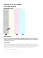
HP Color LaserJet 4700 and 4730 MFP Series
Products - PQ Defects Guide
Overview
Fine Line Segments
Banding 5.88 mm pitch
Poor Transfer (Mottle)
Snail Tracks, Slugs (Fuser)
Rain, dark, OPC 94 mm pitch
Rain, white, OPC 94 mm pitch
Banding, OPC - 94 mm pitch, sharp bands
Offset, Fuser/Electrostatic
Gloss Band/Hot Offset Fuser
Banding CMY developer hue shift 38.5 mm pitch
Banding K developer hue shift 34mm pitch
Background Toner (Front side)
Re-Transfer, Cyan
Random Bands
Snake Bite
38 mm Repetitive Spot (Label Adhesive)
Cleaning Blade Streaks
Marks across page (Fuser 110 Volts in 220 Volts)
Backside Tick Marks (Fuser)
OPC (94 mm) Ghosting
Developer (38/34 mm) Ghosting
Streaks, fine developer
Partial or missing color plane
Toner scatter
Breakdown - chicken tracks
Discharge marks (Similar to chicken tracks)
Banding, small pitch, less than 2.4 mm
Banding OPC Light Damage, 94 mm pitch
Color Toner Missing from Color Documents
Edge to Edge Solid Bands
Light and dark bands on page (at 20mm offset)
Scan/Copy Image Formation Troubleshooting
ADF Streaks
Dark, Blurry Copies or Scans
Overview
Welcome to the HP Color LaserJet 4700 and 4730 MFP Series Printers PQ Defects Guide. This guide
will be updated as needed to reflect new information. Updated: May 02, 2006. Document number:
c00571422.
WARNING:
The information contained in this guide is HP and Channel Partner Use Only.
One of the goals in creating this guide was to capture and preserve PQ defect corner cases; these
are isolated cases for specific print quality defects.
top
How to Properly Define PQ Issues
z
Repetitive Defect
Only refers to dots, dashes, or scratches that repeat at the interval. This does not include
any horizontal or vertical lines.
z
Banding
Only refers to a horizontal line or horizontal hue shift, not dots, dashes, or vertical lines.
z
Streaks
Only refers to a vertical line. No dots, dashes, or horizontal lines.
Repetitive Defect Distances
Replacement
Part
Roller
Distance
34.3 mm
(1.35
inches)
Print Cartridge
Developing cylinder
Print Cartridge
Primary charging roller - Print cartridge or tranfer
37.7 mm
roller (if the defect occurs in only one color, the
(1.48
defective part is the print cartridge; if the defect
inches)
occurs in all colors, the defective part is the ETB.
Print Cartridge
Toner feed roller
42.7 mm
(1.68
inches)
ETB
Media attaching roller
75.0 mm
(2.95
inches)
Fuser
Fuser sleeve
76.0 mm
(2.99
inches)
Fuser
Fuser pressure roller
81.0 mm
(3.19
inches)
Print Cartridge
Photosensitive drum
94.2 mm
(3.71
inches)
Print Image Formation Troubleshooting
Collecting Print Samples from U.S. Customers:
If the customer is experiencing any print quality issues, we need print samples. If we are
replacing an ETB or toner cartridge, they get instructions with the Parts Recovery Program,
that are to be crewed out with the part. If we are not replacing the part, we need print
samples, in all instances.
Collecting Print Samples from Customers in the Rest of the World:
Please send any print samples that you receive through your normal escalation process. If
the issue is not resolved and is not currently documented, collect the defective part as well,
for analysis. The defect may be added to this PQ Guide. If the issue is not currently resolved,
the print samples may be escalated through to division for further analysis and
troubleshooting advice.
the image formation system is the central hub of teh printer. During image formation, an
image of colored toner is formed and then fused onto the paper. The image formation system
consists of the following physical components: four laser/scanner, four print cartridges, ETB,
and fuser.
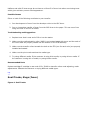
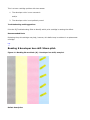
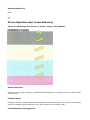
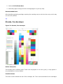
Fine Line Segments
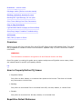
Figure 1: Fine Line Segments
Defect description
Fine horizontal lines/banding in the scan direction (similar to fine developer streaks, only
horizontally creating a linen look).
Contributing Condition
Electrostatic breakdown between cartridge charge roller and the OPC drum creates areas that
attract more toner on the OPC.
Possible Causes
If charge roller resistivity is too low (out of spec) then discharge results creating dark fine line
segments.
Troubleshooting and Suggestions
Isolate problem color and replace corresponding cartridge. This may or may not help the defect.
Can also try changing the humidity in the environment.
Recommended Parts
Toner cartridge. Replacing the cartridge may improve the banding, but cannot be guaranteed.
top
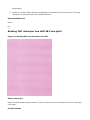
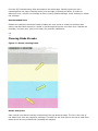
Banding 5.88 mm pitch
Figure 2: Banding, 5.88mm pitch
Defect description
Dark narrow horizontal bands typically visible in half tone colors that repeat at a small pitch
spacing of 5.8 mm.
Possible Causes
Cartridge developer/ OPC drive gear tooth pitch irregularities.
Troubleshooting and Suggestions
z
Print PQ Troubleshooting Suite to isolate color plane producing the defect.
z
If seen in green (secondary), then replace the cyan main motor.
z
If seen in red (secondary), then replace the magenta main motor.
z
If seen in black, then replace the black main motor. The defect will not be seen in yellow.
Recommended Parts
Replace the Drum Drive Motor for the affected color plane.
top
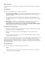
Poor Transfer (Mottle)
Figure 3: Poor Transfer Mottle
Defect description
Halftone and solid fill toner areas do not have a uniform fill of toner but rather are missing toner
which gives a blotchy uneven filled appearance.
Possible Causes
Either or both of the following contribute to poor transfer:
1. Poor development of toner from the developer roller to the OPC drum.
2. Poor or incomplete transfer of toner from the OPC drum to the paper. This can occur from
using too thick or too thin of media.
Troubleshooting and Suggestions
1. Replace toner that is near end of life or has low status.
2. Make sure the media attraction roller (MAR) is not contaminated with toner and the ends of
the roller shaft are properly seated into the holders on the ETB assembly.
3. Make sure the transfer rollers beneath the belt on the ETB (one for each color) are properly
installed and seated.
4. Make sure the print mode matches the media type.
5. Try using different media. If the customer is using thick media, try using thinner media. If
the customer is using thin of media, try using thicker media.
Recommended Parts
Replace cartridge if cartridge is near end of life. If MAR or transfer rollers need adjusting, make
adjustments. Educate the customer on trying different media types.
top
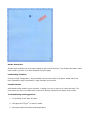
Snail Tracks, Slugs (Fuser)
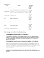
Figure 4: Snail Tracks
Defect description
Streaks that meander but are mostly parallel to the process direction. The streaks resemble a track
mark made by a snail or to water droplets along the page.
Contributing Condition
Printing in High Temperature / High Humidity environment and/or with paper media which has
been exposed to High Temperature / High Humidity environment.
Possible Causes
Acclimated media contains more moisture - causing it to curl or wave as it enters the fuser. The
snail tracks are due to the difference in the toner density caused by the shape of the media.
Troubleshooting and Suggestions
1. Try a sealed, fresh ream of paper.
2. Use approved 75 g/m2 or heavier media.
3. Decrease ambient humidity and temperature.
Recommended Parts
None.
top
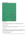
Rain, dark, OPC 94 mm pitch
Figure 5: Rain OPC
Defect description
Small specks of toner that are visible at 94 mm pitch spacing.
Possible Causes
OPC contamination causes toner to stick to the OPC surface, which does not get properly cleaned
off by the cleaning blade. This creates small dots on the page that repeat at 94 mm. It is usually
difficult for the customer to detect the 94 mm repetitive interval on the page.
Troubleshooting and Suggestions
The rain can come and go as the contamination may be cleaned off over time. The defect seems to
occur more frequently during long continuous print jobs.
Recommended Parts
Replace the cartridge.
top
Rain, white, OPC 94 mm pitch
Figure 6: Rain white
Defect description
Small specks of missing toner that are visible on a solid-fill area at 94 mm pitch spacing.
Possible Causes
OPC contamination causes toner to stick to the OPC surface, which does not get properly cleaned
off by the cleaning blade. This creates small white dots on a solid filled area on the page that
repeat at 94 mm. It is usually difficult for the customer to detect the 94 mm repetitive interval on
the page.
Troubleshooting and Suggestions
The rain can come and go as the contamination may be cleaned off over time. The defect seems to
occur more frequently during long continuous print jobs.
Recommended Parts
Replace the cartridge.
top
Banding, OPC - 94 mm pitch, sharp bands
Figure 7: Sharp Band
Defect description
Horizontal sharp light lines appear at a 94 mm pitch spacing.
NOTE:
Dark line appears below the light line in this defect.
Possible Causes
Toner additives and/or foreign materials adhere to the contact area of the OPC cleaning blade and
the OPC drum surface when the drum is stopped. This can be caused when the OPC has not rotated
for several minutes. After the OPC rotates, the defect does go away after a few pages and will stay
away during continuous printing.
Troubleshooting and Suggestions
Customer can set front control panel to turn on 'Pre-rotations'. Go to Configure Device, then go
Print Quality, then Optimize. This will avoid the mark, but it will cause a slower first page out
(20 seconds), and will use up cartridge life.
Recommended Parts
None. Do not replace cartridge, this will not help.
top
Offset, Fuser/Electrostatic
Figure 8: Fuser Offset (Electrostatic offset)
Defect description
Text and image ghost are visible at 76 mm pitch from original text or images.
Contributing Condition
Printing in duplex mode and/or Low Temperature/Low Humidity environment (can also occur in
other environments as well)
Possible Causes
Toner is electrostatically attracted from the paper to the fuser sleeve and then redeposited onto the
paper after one circumferential rotation of the sleeve (76 mm).
Troubleshooting and Suggestions
1. Use Fresh unpacked Media.
2. If printing with rough paper, change fuser mode from rough to normal via the front control
panel.
Recommended Parts
None
top
Gloss Band/Hot Offset Fuser
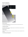
Figure 9: Gloss Bands
Defect description
A wide horizontal band with a higher gloss level (more shine) appears within 76 mm from the
leading edge of the media. Appears in solid fill colors printed in plain and gloss modes.
Contributing Condition
Hot offset occurs on glossy media because the temperature of the fuser pressure roller is higher
when intermittently printing short jobs over a long period of time.
Possible Causes
The fuser sleeve surface temperature is hotter for the initial rotation (76 mm of paper travel) but
then becomes less hot as the fuser heater can not maintain the initial temperature due to the low
thermal mass of the instant on fuser. The increased gloss corresponds to the hotter sleeve
temperature during the initial 76 mm rotation.
Troubleshooting and Suggestions
1. Try printing a couple of pages prior to print job to allow instant on fuser to stabilize fusing
temperature.
2. Customer can also reduce the fuser temperature to reduced via the control panel. This may
change the overall gloss level of printed documents.
Recommended Parts
None.
top
Banding CMY developer hue shift 38.5 mm pitch
Figure 10: Banding 38.5 mm developer hue shift
Defect description
Dark horizontal bands typically visible in C,M & Y halftone colors, that repeat at 38.5 mm developer
roller pitch.
Possible Causes
This is a toner cartridge problem with two causes:
1. The developer roller is non-concentric.
and/or
2. The developer roller is not perfectly round.
Troubleshooting and Suggestions
Print the PQ Troubleshooting Suite to identify which print cartridge is causing the defect.
Recommended Parts
Replacing the print cartridge may help; however, this defect may be evident in a replacement
cartridge.
top
Banding K developer hue shift 34mm pitch
Figure 11: Banding 34 mm black (K) - Developer hue shift, sample 1
Defect description
Dark horizontal bands typically visible in K halftone colors that are repeating at 34 mm developer
roller pitch.
Possible Causes
This is a toner cartridge problem with two causes:
1. The developer roller is non-concentric.
and/or
2. The developer roller is not perfectly round.
Troubleshooting and Suggestions
Print the PQ Troubleshooting Suite to identify which print cartridge is causing the defect.
Recommended Parts
Replacing the print cartridge may help; however, this defect may be evident in a replacement
cartridge.
top
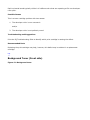
Background Toner (Front side)
Figure 12: Background toner
Defect description
Very light hues of color(s) on non-printed areas of the page.
Contributing Condition
Continuous printing stirs toner and degrades the charge properties. Also the toner in cartridges
that are near end of life have charge properties that are not optimal.
Possible Causes
This is typically a toner cartridge problem caused by positive 'wrong sign' toner being attracted to
the media. This defect can be found most often on glossy media and at cartridge end of life after
printing low coverage.
Troubleshooting and Suggestions
1. Replace cartridge w/ high life or near end of life.
2. Avoid higher resistivity or glossy papers.
3. Try using an sealed, fresh package of paper.
4. Try using the background reduction modes 1 and 2 from the front display panel.
Recommended Parts
Replace cartridge if cartridge is near end of life. Try another media type.
top
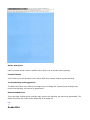
Re-Transfer, Cyan
Figure 13: Re-Transfer, Cyan
Defect description
Cyan color halftone and solid fill toner areas do not have a uniform fill of toner but rather are
missing cyan toner which gives a blotchy uneven filled appearance. This produces a mottled look,
especially in solid green fills but also occasionally shows up in solid red and solid blue fills. The
mottling is on a scale of perhaps 1 to 3 mm. The phenomenon is worse on glossy media, especially
on the second side of a duplex page. It is worse late in cyan cartridge life and may be aggravated
by a yellow cartridge that is fairly new. Environment other than normal (For Example: Low
temperature / low humidity or high temperature / high humidity may also produce more retransfer.
Contributing Condition
Continuous printing stirs toner and degrades the charge properties. Also the toner on cartridges
that are near end of life have charge properties that are not optimal.
Possible Causes
The transfer order for the colors is Y, C, M & K. Cyan toner on the paper surface is attracted back
(retransferred) to the OPC drums of the M & K cartridges as the paper is transported toward the
fuser. Contributing factors are duplex, media and media condition, environment, toner charge, and
cartridge life.
Troubleshooting and Suggestions
Transfer settings have been fine tuned on the HP CLJ4700 & 4730 MFP to reduce retransfer.
Additional changes to transfer settings may have the undesirable side effect of producing poor
transfer. In addition to transfer settings, the environmental sensor in the printer is also used to
adjust transfer settings to reduce retransfer.
Poor transfer is evident mainly on heavier media and will show as a mottled appearance on primary
color, heavy fill areas.
A retransfer optimize mode was created and is accessible through the front panel. It may produce
a higher incidence of poor transfer (especially in solid primaries), but it may help reduce mottle in
solid secondary colors such as green and red.
Recommended Parts
Further improvement is not possible at this time. For customer satisfaction, however, a one-time
cartridge replacement may need to be performed. However, this is not advisable since it is a
temporary fix (it's not a problem with the toner cartridge). It may not be possible to eliminate this
problem.
top
Random Bands
Figure 14: Banding - Random bands
Defect description
Dark horizontal bands visible in halftone colors that occur at random pitch spacings.
Possible Causes
Toner build-up on the developer roller and/or OPC drum causes random impulse banding.
Troubleshooting and Suggestions
The defect should be less visible at the beginning of cartridge life. Replacing the cartridge may
improve the banding, but cannot be guaranteed.
Recommended Parts
Toner cartridge. Replacing the cartridge may improve the banding, but cannot be guaranteed. The
defect should be less visible at the beginning of cartridge life.
top
Snake Bite
Figure 15: Snake bite, sample 1
Defect description
Two irregularly shaped light spots or toner voids that can vary in size from 1 to 4 mm. The two
spots are in the scan direction and are spaced 26 mm apart and 55 mm from the leading edge of
the page.
Contributing Condition
Occurs only when printing from tray 1. Is worse in a High Temperature / High Humidity
environment with acclimated media.
Possible Causes
Caused by media deformation/contamination from the tray 1 pick roller and lift plate contact when
feeding.
Troubleshooting and Suggestions
Use freshly opened media. Print from another tray.
Recommended Parts
None.
top
38 mm Repetitive Spot (Label Adhesive)
Figure 16: Repeating dot at 34 mm or 38 mm - charge roller adhesive
Defect description
Defect shows as small irregularly, shaped dots repeating down the page at a 38 mm interval (OPC
charge roller).
Possible Causes
Customer may be printing with adhesive labels that are either defective, out of spec, or previously
used. The adhesive gets transferred to the OPC and then to the charge roller.
Troubleshooting and Suggestions
Print the PQ Troubleshooting Suite and examine the white page. Identify what color dot is
repeating down the page to identify which print cartridge is causing the defect. If unable to
determine color, remove one cartridge at a time (using 'disable cartridge. check' feature) to isolate
the cartridge.
Recommended Parts
Educate the customer that some brands of labels are more prone to create this problem than
others, and that labels cannot be 'reused' or fed through the printer more than once. Replace the
cartridge, 'one time only' (due to this issue) for customer satisfaction.
top
Cleaning Blade Streaks
Figure 17: Streak, cleaning blade
Defect description
Dark vertical lines that are usually continuous all the way down the page. The line is the color of
the waste toner from the respective cartridge. The dark line will show up over the top of solid filled
areas as well as non-printed areas (including the margins).
Contributing Condition
Cold temperature. Printing in dusty environments and starting the printer below 15o Centigrade.
Possible Causes
There are two reasons for this:
1. A foreign particle can become trapped in the cleaning and create an opening for the waste
toner to streak onto the page. A foreign particle can also cut a notch into the cleaning blade
and cause the same result.
2. Cold temperatures cause the cleaning blade to be stiffer and cause small openings to occur
between the blade and OPC surface.
Troubleshooting and Suggestions
Print the PQ Troubleshooting Suite and look at the vertical streaks on the blank page. Replace the
defective cartridge. Reprint the PQ Troubleshooting Suite to verify the correct cartridge was
replaced. If the customer has the printer in a cold environment, suggest the printer be run in a
warmer temperature. The defect can come and go, as either the temperature is raised or the
foreign particle works its way out.
Recommended Parts
Replace the toner cartridge if needed.
top
Marks across page (Fuser 110 Volts in 220 Volts)
Figure 18: Marks across page (fuser)
Defect description
Marks appear as short segments that are grouped together as a band. This defect occurs only if
wrong fuser voltage is being used (When using a 110 Volt fuser in a 220 Volt engine.)
Possible Causes
Using the wrong fuser voltage impacts the fusing temperature and fuser sleeve bumps develop
causing the 'Marks.' The defect will be noticed with Glossy media.
Troubleshooting and Suggestions
Check if the customer is using the correct fuser voltage with the correct engine voltage.
110 Volt fuser has a white Serial number Label.
220 Volt Fuser has a pink Serial number Label.
Recommended Parts
New Fuser (with the correct voltage).
top
Backside Tick Marks (Fuser)
Figure 19: Backside Tick Marks, Simplex
Figure 20: Backside Tick Marks, Duplex
Defect description
Tick marks aligned in one or two streaks on the backside of the page. This usually occurs on glossy
duplex pages.
Possible Causes
Continuous printing with envelopes or with narrow media could create cuts on the Fuser Pressure
Roller.
Troubleshooting and Suggestions
Verify with the customer if cuts are seen on the pressure rollers and if they have been printing with
envelopes and/or with narrow media.
Recommended Parts
New fuser.
top
OPC (94 mm) Ghosting
Figure 21: Ghosting, OPC
Defect description
OPC ghosting is when a printed object is discernable further down the page at 94 mm offset from
original.
Possible Causes
Photoconductive drum ghost can be caused in different ways:
1. Incorrect transfer settings: This can occur by running media in an incorrect mode. It may
also occur if there are hardware problems with the transfer circuitry (such as the spring
contacts to the ETB).
2. Some ghosting may occur on heavy glossy media, especially in high temperature, high
humidity environments. This is a consequence of transfer settings being optimized to reduce
re-transfer.
3. Erase failure: The printer has a LED that shines into a light pipe which illuminates the
photoconductive drum as it rotates. Anything that stops light from reaching the
photoconductive drum will cause a ghost. This could occur by light pipe breakage, hardware
failure of the LED or associated circuitry, or by obstruction of the light between the engine
and the light pipe (by toner, or by a broken mechanism).
Troubleshooting and Suggestions
1. Attempt to isolate which cartridge or cartridges are producing the ghosting image. (Disable
cartridge check function can help facilitate this.)
2. Check to see if the light pipe is in any way dislodged from its normal position on the
cartridge.
3. Try using a soft tissue to clean any toner, dust or debris accumulation away from the light
emitting length of the light pipe.
If the customer is using heavy glossy media (or heavier, slicker media) in a high temperature, high
humidity environment, this has been found to be one of the most frequent causes, so ask the
customer to try different media (either lighter or less glossy). Lastly, check the contacts between
the ETB and the engine - the copper contacts on the left side of the ETB and the spring contacts to
the left of the cartridges.
Recommended Parts
As a last resort, replace the cartridge responsible for the ghosting.
NOTE:
A cartridge may not fix the problem and if the problem occurs with the new cartridge, the
printer may require on-site diagnosis.
top
Developer (38/34 mm) Ghosting
Figure 22: Ghost, developer 01
Defect description
Developer ghosting is when a printed object is discernable further down the page. For ghosting
caused by the developer roller, the repeated image appears at 38 mm pitch for cyan, magenta, and
yellow, and 34 mm for black.
Possible Causes
Developer ghosting is caused by the charge characteristics of the toner. Most often it is seen as a
ghost of a solid fill cut-out (like a ghost of white letters in a solid blue field). Blue may produce
worse results than other colors. It is worse early in cartridge life (first few hundred pages) but may
persist. Results may be better on the first page of a job than on subsequent copies.
Troubleshooting and Suggestions
1. Check the printer's transfer settings, including print and optimize modes, as this can have a
significant effect on cartridge ghosting.
2. Perform Full Calibrate Now.
3. Alternating high coverage and low coverage pages in a job may help.
Recommended Parts
After identifying ghosting cartridge, replacing the cartridge may be tried one time only as this may
not solve the problem.
top
Streaks, fine developer
Figure 23: Streaks, fine developer
Defect description
Thin streaks print in halftone areas. These lines may appear in one color (cyan), or may appear in
any combination of colors (CMYK).
Possible Causes
This issue is seen towards the end of the cartridge's life. Toner has accumulated on the cartridge's
doctor blade. The purpose of the doctor blade is to create an even level of toner onto the
developing roller. Since the doctor blade no longer has an even surface, uneven amounts of toner
are placed on the developing roller, then transferred onto the OPC.
Troubleshooting and Suggestions
1. Print the PQ troubleshooting pages from the printer to verify which cartridge(s) is showing
the vertical lines.
2. Print the supplies status page to gauge the percent life remaining for each infected cartridge.
If any cartridges are reading order supplies (below 20%), recommend that the customer
replace the cartridge. Otherwise, replace the cartridge under warranty.
Recommended Parts
Replace only the affected print cartridge(s).
top
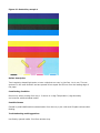
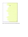
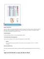
Partial or missing color plane
Figure 24: Partial or missing color plane, typical of misaligned gears on main drive
assembly
Figure 25: Partial or missing color plane, black - Config Page, typical of misaligned gears
on the main drive assembly
1 - Paper motion.
2 - Faded blue (No black).
Figure 26: Faded yellow, typical of misaligned cable cover
Figure 27: Partial color plane, typical of poor OPC grounding image
Full Missing color plane, typical of poor OPC grounding image
Defect description
Images appear to change color or completely fade away, either from side to side or top to bottom.
Possible Causes
1. OPC grounding spring not making adequate contact. In this case, additional defects that may
occur intermittently along with this, in the same color, are edge to edge banding and
light/dark bands 20mm apart.
2. Main drive assembly was not aligned properly during reinstallation.
3. If in yellow, improper reinstallation of the cable cover on the paper feed assembly.
Troubleshooting and Suggestions
1. Be sure the cartridge is not “low” or running in “override” mode.
2. Verify 10.92.xx error does not appear in event log as associated with this failure. If failure is
associated with a 10.92.xx error in the event log, see “10.92.00 and black color plane
missing” document. This error is associated with only the black color plane.
3. Run the laser scanner motor test to make sure that the laser scanner is working correctly. If
the laser scanner is not working, replace the laser scanner for the associated color.
4. If the main drive assembly has recently been removed, follow the steps in the service manual
to realign the gears on the main drive assembly.
5. If in yellow and the paper feed assembly has recently been removed, check that the cable
cover is installed properly.
6. See the service advisory on this issue for replacement of the OPC gears.
NOTE:
Do not replace the print cartridge for this issue, unless it indicates an “order” or
“replace” message.
Recommended Parts
If all other issues have been ruled out, replace the OPC grounding springs per the service advisory.
top
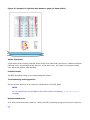
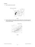
Toner scatter
Figure 28: Typical leading edge forward scatter on heavy media in dry environment
1 - Leading edge
2 - Feed direction
3 - Forward scatter
Defect description
Printed text appears to be fuzzy, especially black text superimposed over colored background. Most
commonly seen when duplexing.
Possible Causes
This scatter is most common with dry paper conditions that can occur in low humidity
environments or when printing on both sides. It is most common on heavy media. Above is a photo
of typical performance on heavy media (65#) from a low temperature and low humidity
environment. The forward scatter is most easily seen in the black toner but can also occur in the
color toners.
Typically seen toward the end of print cartridge life.
Troubleshooting and Suggestions
In low humidity conditions, the use of freshly opened media can help reduce the tendency for
forward scatter, especially for single sided printing. Media that has been allowed to dry in the paper
trays for extended periods can be susceptible to forward scatter.
More flexible media will sometimes reduce the forward scatter since its path is more quickly
controlled than stiff media. Thick media can be especially susceptible to leading edge forward
scatter.
Media with different surface properties will sometimes reduce the amount of scatter. The toner and
the media surface can tend to hold an electrostatic charge too long on some media and are thus
susceptible to discharge in the paper path.
Scatter may be reduced after printing 100 pages, due to the normal toner maintenance process
within the print cartridge (every 100 pages the toner is "stirred" to retain the appropriate charge
properties). Try setting the paper type to "light <75 g/m²". Replacing the toner cartridge may
temporarily solve the problem, if seen later in the print cartridge life. It may reoccur for the
reasons with a replacement cartridge. The only way to completely resolve the issue is to try
creating a more humid operating environment.
Recommended Parts
None.
top
Breakdown - chicken tracks
Figure 29: Breakdown (chicken tracks)
Defect description
Breakdown chicken tracks, simplex mode also called 'discharge marks' are an irregular, wave-like
pattern that resembles a chicken track imprint and appear in lighter halftone image areas. Typically
at the trailing edge of the page.
Contributing Condition
Printing on thin paper or paper which has been exposed for a long time in Low Temperature / Low
Humidity environment. Operating the printer in low temperature low humidity environments.
Possible Causes
The toner on the paper scatters due to the electrostatic discharging when the trailing edge of the
paper separates from the ETB.
Troubleshooting and Suggestions
1. Use 75 g/m2 - 120 g/m2 media.
2. Use fresh paper.
3. Increase the ambient temperature and humidity.
Recommended Parts
None.
top
Discharge marks (Similar to chicken tracks)
Figure 30: Discharge (chicken tracks)
1 - Typical trailing edge discharge on dry media.
Defect description
Discharge marks can appear at the leading and trailing print areas in lighter halftone image areas,
which appear as an irregular, wave-like pattern that resembles a chicken track imprint. These
discharge marks are most common with dry paper conditions that can occur in low humidity
environments or when printing on both sides.
Leading Edge: The leading print area marks tend to be thin tendrils of disturbed toner and can be
up to 20 mm or longer from the leading paper edge. The leading edge marks shown in the above
image are most easily seen in the black toner but also occur in the color toners.
NOTE:
Leading print area or leading edge refers to the first edge exiting the printer and may or may
not be the top of the image.
Trailing Edge: Trailing edge marks tend to be obvious fan marks of disturbed toner. They can be
up to 10 to 15 mm from the tailing paper edge. As with the leading edge marks, trailing edge
discharge marks are most easily seen in the black toner but also occur in the color toners. See the
above image.
Contributing Condition
Operating the printer in a low temperature, low humidity environment and/or printing on thin
paper or paper which has been fully acclimated to a low temperature, low humidity environment.
In dry conditions, electrostatic discharge can occur as paper touches or separates from various
surfaces in the printer. Discharge can occur when paper goes between rollers, as paper separates
from the transport belt, and as paper is directed with guides and ribs. This discharge can disturb
the toner on the surface of the paper causing various visible patterns.
The patterns above typically occur as the paper separates from the ETB and as the paper is guided
into the fuser rollers. When the paper is captured in the fuser and still electrostatically attached to
the paper transport belt, the path the paper takes between the belt and the fuser can be controlled
and the discharge marks minimized. However, the leading and trailing edges are difficult to control
and discharge can occur as the paper exits the transport belt or touches guides.
Troubleshooting and Suggestions
In low humidity conditions, the use of freshly opened media can help reduce the discharge marks,
especially for single sided printing. Media that has been allowed to dry in the paper trays for
extended periods can be susceptible to discharge marks.
If the defect appears in normal environmental conditions (T > 19o degrees C, % RH > 20%), then
more flexible media will sometimes reduce the discharge since its path is more easily controlled
than stiff media. Thick media can be especially susceptible to trailing edge discharge.
Media with different surface properties (lower surface resistivity) will sometimes reduce the amount
of discharge. The toner and the media surface can tend to hold an electrostatic charge too long on
some media and are thus susceptible to discharge in the paper path.
Recommended Parts
None.
top
Banding, small pitch, less than 2.4 mm
Figure 31: Less than 2.4 mm Banding, small pitch
Defect description
Dark narrow horizontal bands typically visible in half tone colors that repeat at a small pitch
spacing of 1.6 to 2.4 mm.
Possible Causes
This is caused by gear chatter between various engine and cartridge gears.
Troubleshooting and Suggestions
Small pitch banding is inherent to the print process due to the meshing of gears.
Recommended Parts
None. Reseating or Replacing the cartridge may improve the banding, but cannot be guaranteed.
top
Banding OPC Light Damage, 94 mm pitch
Figure 32: 94 mm Banding - OPC, light damage
Defect description
Dark narrow horizontal bands (Approximately 10 mm wide) typically appear in halftone colors at
the 94 mm OPC drum pitch interval.
Contributing Condition
Improper storage and light exposure of OPC drum.
Possible Causes
Extended light exposure of OPC drum surface changes charge properties of OPC.
Troubleshooting and Suggestions
Ask the customer if they are storing the cartridges outside the box and/or bag. Warn the customer
that this is the cause and to avoid this in the future. The light damage does fade over time, but can
take awhile. Replace the cartridge this first time.
Recommended Parts
Toner cartridge.
top
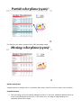
Color Toner Missing from Color Documents
Figure 33: Color missing
Defect description
Color toner is missing either on the full page or on a portion of the page. Color may be evident, but
extremely faint. If calibration occurs while the ETB is in this state, two stripes of toner (calibration
patches) may be on the backside of images, along with 54.xx errors in the event log.
Possible Causes
The transfer rollers in the ETB are not alienating properly.
Troubleshooting and Suggestions
1. Verify that the color cartridges are not running in Override at Out Mode. Print a Supplies
Status Page and check for the message “Supply Used After Out with OVERRIDE” under the
cartridge part number. When a cartridge is used in this mode, the toner may be depleted,
causing that color to fade.
2. Confirm that the image is not merely printed in grayscale. If the full image is printed (i.e. if
areas that should be printed in color are printed in grayscale), then the printer may be
experiencing one of the following:
{ The customer may be using a black-only print driver.
{
{
"RESTRICT COLOR USE” may be set to “COLOR IF ALLOWED” or “DISABLE COLOR”
through the control panel or EWS.
“COLOR SUPPLY OUT” may be set to “AUTOCONTINUE BLACK” through the control
panel or EWS.
3. Verify that all three color planes (CMY) are missing from or appear very, very faint on the
Supplies Status Page.
4. Set Color/Black Mix in the System Setup Menu to the default setting of “Auto”. The “Mostly
Black Pages” setting may exacerbate the issue.
5. Open and close and the ETB. This will sometimes resolve the issue temporarily, so the
product will work correctly until a replacement ETB can be obtained.
Recommended Parts
Replace the ETB.
NOTE:
Do not replace the print cartridges for this defect.
top
Edge to Edge Solid Bands
Figure 34: Example of Edge to Edge Solid Bands
Defect description
A band or bands of varying width appear randomly on pages, from edge to edge. Additional defects
that may occur intermittently along with this, in the same color, are partial or complete missing
color plane and light/dark bands 20mm apart.
Possible Causes
The OPC grounding spring is not making adequate contact.
Troubleshooting and Suggestions
See the service advisory on this issue for replacement of the OPC gears.
NOTE:
Do not replace the print cartridge for this issue unless it indicates an “order” or “replace”
message.
Recommended Parts
If all other issues have been ruled out, replace the OPC grounding springs per the service advisory.
top
Light and dark bands on page (at 20mm offset)
Figure 35: Example of Light and dark bands on page (at 20mm offset)
Defect description
A light band (toner missing) followed 20mm’s later by a dark band (extra toner). Additional defects
that may occur intermittently along with this, in the same color, are partial or complete missing
color plane and edge to edge banding.
Possible Causes
The OPC grounding spring is not making adequate contact.
Troubleshooting and Suggestions
See the service advisory on this issue for replacement of the OPC gears.
NOTE:
Do not replace the print cartridge for this issue unless it indicates an “order” or “replace”
message.
Recommended Parts
If all other issues have been ruled out, replace the OPC grounding springs per the service advisory.
top
Scan/Copy Image Formation Troubleshooting
NOTE:
Applicable to the Color LaserJet 4730mfp only.
top
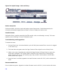
ADF Streaks
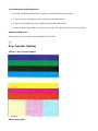
Figure 36: Example of ADF Streaks
Defect description
Using the automatic document feeder (ADF), color copies and scans of dark images have blue, red
and green streaks down the length of the copy or portion of the copy. The streaks may not be
evident in lighter color tones or where only one color of toner is applied.
Possible Causes
Debris has settled on the glass or in the Mylar scan window in between the page and the scanner.
If the dust is large and black the streaks will be black. If the dust is white, the streak will be white.
If the dust is extremely small it may block only one pixel, resulting in red, green or blue streaks.
Troubleshooting and Suggestions
1. Wipe the glass with a lint free rag to remove any dust. Warning: facial tissue will create more
dust.
2. Replace the mylar in the ADF scan window.
3. Use the flatbed scanner. When the flatbed scanner is used, the page stays stationary and the
scanner moves, so even if dust is on the glass streaks will not be apparent.
4. Copy in black and white. In a black and white scan, the small red, green and blue lines are
not seen and the light gray streaks are less obvious.
5. Change the standard copy options – An option that may improve the streaks includes
changing the Page Content setting for the original to Photo. Also, setting the darkness to a
lighter setting may help and will also save toner.
Recommended Parts
Do not replace any parts for this issue. Use the workarounds above.
top
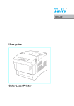
Dark, Blurry Copies or Scans
Figure 37: Printed image - correct
Figure 38: Copied image - dark and blurry
Defect description
Copies print dark, with blurry text and blotchy areas of extra toner. Printed documents print
correctly and scanned images (Scan to Email or Scan to Folder) also look correct.
Possible Causes
Calibration failure, possibly caused by the ETB transfer rollers not alienating correctly. This issue
typically occurs following a “normal” calibration cycle.
Troubleshooting and Suggestions
To isolate the issue:
1. Print an Event Log - the last calibration cycle will likely have caused 54.xx errors to be logged
in the Event Log.
2. The issue does not appear when the Page Content of the original is set to Glossy Photo.
3. Make a color copy, describing the original with Page Content of Glossy Photo to ensure the
issue does not appear. The original used to make the copy need not be an actual glossy
photo. However, if it is not, the resulting copy may contain a moiré pattern, but the dark,
blotchy areas will be gone.
4. Once the issue is verified, upgrade to at least firmware version 46.121.2, which resolves this
issue.
Recommended Parts
Do not replace any parts. Upgrade to at least firmware version 46.121.2, which resolves this issue.
top