1
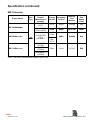
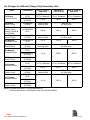
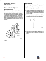
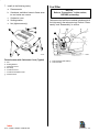
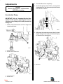
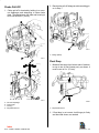
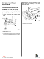
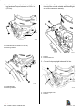
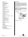
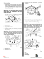
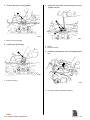
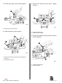
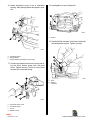
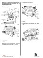
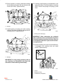
FUEL SYSTEM 5 B 70389 WEBER 4 BARREL CARBURETOR Index Table of Contents Page Identification . . . . . . . . . . . . . . . . . . . . . . . . . . . . . 5B-1 Replacement Parts Warning . . . . . . . . . . . . . . . 5B-1 Torque Specifications . . . . . . . . . . . . . . . . . . . . . 5B-1 Tools . . . . . . . . . . . . . . . . . . . . . . . . . . . . . . . . . . . 5B-1 Specifications . . . . . . . . . . . . . . . . . . . . . . . . . . . . 5B-2 MCM Carburetor . . . . . . . . . . . . . . . . . . . . . . 5B-2 MIE Carburetor . . . . . . . . . . . . . . . . . . . . . . . . 5B-3 Jet Changes for Altitude (Change Only Secondary Jets) . . . . . . . . . . . . . . . . . . 5B-4 MCM Carburetor Adjustment Specifications . . . . . . . . . . . . . . . . . . . . . . . . 5B-5 MIE Carburetor Adjustment Specifications . . . . . . . . . . . . . . . . . . . . . . . . 5B-5 Description . . . . . . . . . . . . . . . . . . . . . . . . . . . . . . 5B-6 Precautions . . . . . . . . . . . . . . . . . . . . . . . . . . . . . 5B-6 Important Service Information . . . . . . . . . . . . . . 5B-7 Weber Carburetor Adjustable Accelerator Pump . . . . . . . . . . . . . . . . . . . . . 5B-7 Hard Starting . . . . . . . . . . . . . . . . . . . . . . . . . . 5B-7 Carburetor Metering Rod And Jet Indentification . . . . . . . . . . . . . . . . . . . . . . . . 5B-8 Maintenance . . . . . . . . . . . . . . . . . . . . . . . . . . . . . 5B-9 Flame Arrestor . . . . . . . . . . . . . . . . . . . . . . . . 5B-9 Fuel Filter . . . . . . . . . . . . . . . . . . . . . . . . . . . 5B-10 Adjustments . . . . . . . . . . . . . . . . . . . . . . . . . . . . 5B-11 Accelerator Pump . . . . . . . . . . . . . . . . . . . . 5B-11 Choke Pull-Off . . . . . . . . . . . . . . . . . . . . . . . 5B-12 Float Drop . . . . . . . . . . . . . . . . . . . . . . . . . . . 5B-12 Float Level . . . . . . . . . . . . . . . . . . . . . . . . . . . 5B-13 Idle Speed and Mixture Adjustments . . . . . . . 5B-14 Thunderbolt IV Equipped Engines . . . . . . 5B-14 Thunderbolt V Equipped Engines . . . . . . . 5B-16 Repair . . . . . . . . . . . . . . . . . . . . . . . . . . . . . . . . . 5B-17 Removal . . . . . . . . . . . . . . . . . . . . . . . . . . . . 5B-17 Installation . . . . . . . . . . . . . . . . . . . . . . . . . . . 5B-18 Exploded View . . . . . . . . . . . . . . . . . . . . . . . 5B-24 Disassembly . . . . . . . . . . . . . . . . . . . . . . . . . 5B-25 Cleaning and Inspection . . . . . . . . . . . . . . . 5B-34 Reassembly . . . . . . . . . . . . . . . . . . . . . . . . . 5B-35 NOTICE For information and procedures on troubleshooting, refer to Section 1C. Index 5B - WEBER 4 BARREL CARBURETOR 5B-0 - WEBER 4 BARREL CARBURETOR 90-823224--2 796 Identification Torque Specifications Fastener Location in. lb. Carburetor To Manifold 132 Fuel Line To Carburetor lb. ft. N·m 15 18 24 Tools Description a 70389 a - Weber Identification Number Location Part Number Universal Carburetor Gauge 91-36392 Tachometer 91-59339 Universal Carburetor Stand Torx Screwdriver Replacement Parts Warning Obtain Locally (15,20,25) TORX SCREWDRIVERS ! WARNING Electrical, ignition and fuel system components on your MerCruiser are designed and manufactured to comply with U.S. Coast Guard Rules and Regulations to minimize risks of fire and explosion. Weber carburetors will have a “star” shaped socket in the head of some screws. A TORX screwdriver must be used on this type of screw. The sizes used are numbers 15, 20 and 25. Use of replacement electrical, ignition or fuel system components, which do not comply with these rules and regulations, could result in a fire or explosion hazard and should be avoided. Index 90-823224--2 796 WEBER 4 BARREL CARBURETOR - 5B-1 Specifications MCM Carburetor Secondary Jet Size Metering Rod Number Metering Rod Spring Color .107 in.1 .098 in.1 16-6542 Pink 3310-806969 (9780S) .104 in. .098 in. 16-757347 Green 3310-818659 (9772) .107 in.1 .098 in.1 16-6542 Pink 3310-805569 (9777) .107 in.1 .098 in.1 16-7147 Pink 3310-806969 (9780) .104 in. .098 in. 16-757347 Green MCM 454 Magnum SN OF304599 and below 3310-816917 (9773) .107 in. .107 in. 16-6542 Pink MCM 454 Magnum SN OF305000 and Above MCM 454 Magnum 3310-806755 ( , 9779S)) (9779, .106 in. .092 in. 16-757347 Green MCM 502 Magnum 3310-805341 (9776) 3310-806791 (9776S) .110 in. .101 in. 16-7147 Pink Engine Model Carb Type MCM 7.4L SN OF352105 and Below MCM 7.4L SN OF352106 and Above MCM 7.4L Bravo Three SN OF070156 and Above MCM 7.4L Bravo Three SN OF070155 and Below MCM 7.4L WFB Mercury Number (Manufacturer Number) Primary Jet Size 3310-818659 (9772) 1 7.4L Engines with the following serial numbers may have staggered jets in the main and/or secondary jets. They should be changed to jets listed above for that respective carburetor. MCM (Stern Drive) serial numbers OF022828 and below MIE (Inboard ) serial number OD857999 and below Index 5B-2 - WEBER 4 BARREL CARBURETOR 90-823224--2 796 Specification (continued) MIE Carburetor Engine Model Carb Type MIE 7 7.4L 4L Bluewater 8 2L Bluewater Bl t MIE 8.2L WFB Mercury Number (Manufacturer Number) Primary Jet Size Secondary Jet Size Metering Rod Number Metering Rod Spring Color 3310-818659 (9772) .107 in. .098 in. 16-6542 Pink 3310-806969 ((9780, 9780S) S) .104 104 in. in .098 098 in in. 16-757347 Green Starboard Side .107 in. 098 in. i .098 16 6542 16-6542 Pi k Pink .110 iin. i .101 in. 16-7147 Pi k Pink 3310-817693 ( (9774) ) See Note 1 Port Side .104 in. 3310-805341 (9776S) L Bluewater Bl MIE 8.2L 3310-805341 (9776SA) 3310-806971 (9776SB) Note1: This model carburetor had staggered primary jets. Index 90-823224--2 796 WEBER 4 BARREL CARBURETOR - 5B-3 Jet Changes for Altitude (Change Only Secondary Jets) Part Number 5000 ft. (1525 m) and below 5000-9000 ft. (1525-2745 m) 9000 ft. (2745 m) and above 3310-818659A (9772) .098 in. Port .077 In. Starboard .092 in. Port .074 in. Starboard .089 in. Port .071 in. Starboard 3310-818659A (9772SA) .098 in. .092 in. .089 in. 3310-806969 (9780S) Stock 3 Step Metering Rod 7.4L Bravo Three Electric Choke Serial # OF838819 to OF800699 3310-805569A (9777) .098 in. 7.4L Bravo Three Electric Choke 3310-806755A (9779S) Stock 3 Step Metering Rod 454 Magnum Automatic Choke 3310-816917A (9773) .107 in. 454 Magnum Electric Choke 3310-806755A (9779S) Stock 3 Step Metering Rods Model 7.4L Bravo Automatic Choke C 7.4L Bravo Electric Choke g 502 Magnum Automatic Choke C 502 Magnum Electric Choke 7.4L Inboard Automatic Choke C 7.4L Inboard Electric Choke 8.2L Inboard Automatic Choke C 8.2L Inboard Electric Choke Elevation Kit #1 (See Note) .092 in. .089 in. Elevation Kit #1 (See Note) .101 in. .098 in. Elevation Kit #2 (See Note) 3310-805341 (9776) 3310-806791A (9776SA) .101 in. i .095 in. i .092 in. i 3310-818659A (9772) .098 in. Port .077 In. Starboard .092 in. Port .074 in. Starboard .089 in. Port .071 in. Starboard 3310-818659A (9772SA) .098 in. .092 in. .089 in. 3310-806969 (9780S) Stock 3 Step Metering Rod 3310-806971A (9776SB) Elevation Kit #1 (See Note) 3310-805341 (9776) 3310-806791A (9776SA) i .101 in. i .095 in. i .092 in. 3310-806971A (9776SB) NOTE: Elevation Kit Number 1 (Part Number 809615) Elevation Kit Number 2, 454 Magnum Only (Part Number 809620) Index 5B-4 - WEBER 4 BARREL CARBURETOR 90-823224--2 796 UNIT OF MEASUREMENT In. (mm) ALL MEASUREMENTS ARE ± 1/64 In. (0.4 mm). MCM Carburetor Adjustment Specifications Engine Model 7.4L / 7.4L Bravo Three 454 Bravo 502 Bravo Carburetor Manufacturer Number 9772, 9777 9779S, 9780S 9773, 9779S 9776, 9776SA, 9776SB Float Level 1-9/32 in. (33 mm) Float Drop 2 in. (51 mm) Pump Rod Hole Location Third Hole From End Accelerator Pump 7/16 in. (11 mm) 1 Choke Pull-Off 15/64 in. (6 mm) Choke Coil Rod Top Of Rod Even With Bottom Of Lever Hole 2 Preliminary Mixture Idle Screw Setting 1-1/4 Turns MIE Carburetor Adjustment Specifications Engine Model 7.4L 8.2L Carburetor Manufacturer Number 9772, 9780S 9774, 9776, 9776S, 9776SB Float Level 1-9/32 in. (33 mm) Float Drop 2 in. (51 mm) Pump Rod Hole Location Third Hole From End Accelerator Pump 7/16 in. (11 mm) 1 Choke Pull-Off 15/64 in. (6 mm) Choke Coil Rod Top Of Rod Even With Bottom Of Lever Hole 2 Preliminary Mixture Idle Screw Setting 1 Measured 1-1/4 Turns from top of carburetor to bottom of S-link 2 Remove choke rod from lever hole. Choke held closed and choke rod pushed down with top edge of rod even with bottom edge of hole. Index 90-823224--2 796 WEBER 4 BARREL CARBURETOR - 5B-5 Description Weber WFB carburetor is unique in design, as the main body and flange are cast as a one piece unit. This, along with the bowl cover, make up the two piece construction which is made of light, durable aluminum to dissipate heat. There are two separate float circuits. Each float circuit supplies fuel to a primary low speed circuit and a primary and secondary high speed circuit. The bowls are vented to the inside of the air horn. A connecting vent passage effects a balance of the air pressure between the two bowls. The float needle valves are installed at an angle to provide the best possible seating action on the needles. This provides better needle response to float movement, also. The high speed circuits use staged step-up rods in the main metering jets to control the amount of fuel admitted to the nozzles. The position of the step-up rod is controlled by manifold vacuum applied to the vacuum piston. A primary air bleed located in the venturi cluster prevents a rich condition or bog as the high speed circuit is reactivated after deceleration. Small “L” shaped metal tabs, called “distribution tab(s),” are attached to some venturi clusters and protrude into the air stream at the proper location to aid distribution of fuel on selected applications. Precautions ! WARNING Always disconnect battery cables from battery BEFORE working on fuel system to prevent fire or explosion. ! WARNING Be careful when cleaning flame arrestor and crankcase ventilation hose: gasoline is extremely flammable and highly explosive under certain conditions. Be sure that ignition key is OFF. DO NOT smoke or allow sources of spark or open flame in area when cleaning flame arrestor and crankcase ventilation hose. ! WARNING Be careful when changing fuel system components: gasoline is extremely flammable and highly explosive under certain conditions. Be sure that ignition key is OFF. DO NOT smoke or allow sources of spark or open flame in area while changing fuel filter. Wipe up any spilled fuel immediately. Fuel Supply Connections ! WARNING Avoid gasoline fire or explosion. Improper installation of brass fittings or plugs into fuel pump or fuel filter base can crack casting and/or cause a fuel leak. • Apply #592 Loctite Pipe Sealant with Teflon to threads of brass fitting or plug. DO NOT USE TEFLON TAPE. • Thread brass fitting or plug into fuel pump or fuel filter base until finger tight. • Tighten fitting or plug an additional 1-3/4 to 2-1/4 turns using a wrench. DO NOT OVER-TIGHTEN. • Install fuel line. To prevent over-tightening, hold brass fitting with suitable wrench and tighten fuel line connectors securely. • Check for fuel leaks. ! WARNING Make sure no fuel leaks exist, before closing engine hatch. ! CAUTION DO NOT operate engine without cooling water being supplied to water pickup holes in gear housing or water pickup inlet, or water pump impeller will be damaged and subsequent overheating damage to engine may result. Index 5B-6 - WEBER 4 BARREL CARBURETOR 90-823224--2 796 Important Service Information Hard Starting Weber Carburetor Adjustable Accelerator Pump 1. Before starting engine, remove flame arrestor then operate throttle to see if choke closes. The accelerator pump lever on Weber Carburetors has three holes in it. The closest hole to the lever’s pivot point is the richest, the second hole is leaner and the hole furthest away is the leanest. All production carbs have the pump rod installed in the closest (richest) hole. If you are having a “rich” bog on acceleration, move the rod to the second or third hole. Weber put the three holes in the lever so the amount of fuel delivered by the accelerator pump could be changed. 2. If choke is stuck open, check choke stove link rod and choke linkage on both sides of carburetor for cause of sticking. Possible paint or interference to rod or linkage. If a hard starting condition exists, after engine has not been operated for a period of time, proceed with the following: 3. If choke plate does not close tight step 2 or 3, then choke link rod will have to be bent to make it shorter so it will close choke plate completely. a 73716 a - Bend Here To Shorten a 4. After installing, ensure that the rod does not rub against stove cover or carburetor throughout its travel. b c 70472 a - Rich b - Lean c - Leaner Index 90-823224--2 796 WEBER 4 BARREL CARBURETOR - 5B-7 METERING JETS Carburetor Metering Rod And Jet Indentification The metering jets in this carburetor are taller than the jets in a standard carburetor. METERING ASSEMBLY Three Step Two Step The metering rod assemblies are different in the following ways: Three Step b a a d b 73728 c a - Three Step Metering Rod b - Two Step Metering Rod METERING ROD HAS “THREE STEPS” -VSTWO e 73732 Three Step 73726 b Two Step a Two Step 73724 d c PISTON SHAPE IS DIFFERENT AND HAS A SECOND SPRING e 73729 a b c d e - Three Step Piston Metering Rod Spring Jet Piston Cover 73730 Two Step 73727 Index 5B-8 - WEBER 4 BARREL CARBURETOR 90-823224--2 796 PISTON ASSEMBLY COVER IS HIGHER ELECTRIC CHOKE The electric choke should be set with marks aligned. 73735 Three Step Two Step 73725 74104 Maintenance 73736 PISTON BORE HAS A STEP ON THREE STEP MODEL Flame Arrestor NOTICE Refer to “Precautions,” in this section, BEFORE proceeding. 5. Remove (in the following order): a. Nut b. Sealing washer c. Carburetor cover d. Crankcase ventilation hoses from flame arrestor and rocker arm covers e. Flame arrestor 6. Clean and inspect: a. Clean flame arrestor in solvent and blow dry with compressed air. b. Clean crankcase ventilation hoses. 73737 c. Inspect crankcase ventilation hoses for cracks or deterioration, and replace if necessary. Index 90-823224--2 796 WEBER 4 BARREL CARBURETOR - 5B-9 7. Install (in the following order): Fuel Filter a. Flame arrestor b. Crankcase ventilation hoses to flame arrestor and rocker arm covers NOTICE Refer to “Precautions,” in this section, BEFORE proceeding. c. Carburetor cover Carburetor inlet fuel filter is installed in bottom side of fuel inlet seat (in the carburetor top). Refer to “Disassembly” and “Reassembly” to service. d. Sealing washer e. Nut (tighten securely) a c b a d b d e e f 71372 Flame Arrestor with Carburetor Cover (Typical) a b c d e f g - Nut Sealing Washer Carburetor Cover Sta-Strap Crankcase Cover Crankcase Ventilation Hose Flame Arrestor 70447 a - Fuel Inlet Seat (with Gasket) b - Fuel Inlet Filter Index 5B-10 - WEBER 4 BARREL CARBURETOR 90-823224--2 796 2. Close throttle valves completely. Adjustments NOTICE Refer to “Precautions,” in this section, BEFORE proceeding. 3. Accelerator pump is set at 7/16 in. (11 mm), which is measured from the carburetor top to the bottom of the S-link as shown. Accelerator Pump IMPORTANT: Refer to “Important Service Information” in this section, regarding the three accelerator pump linkage holes and placement of linkage rod. 1. Back out idle speed screw until it no longer contacts throttle lever. 70472 4. Adjustment of accelerator pump is done by bending the linkage as necessary to achieve the proper dimension as stated above. a b 70474 a - Idle Speed Screw b - Throttle Lever Contact Point a 70473 a - Bend Here a b 70473 a - Idle Speed Screw b - Throttle Lever Index 90-823224--2 796 WEBER 4 BARREL CARBURETOR - 5B-11 Choke Pull-Off 1. Choke pull-off is checked by holding in on vacuum diaphragm and attempting to close choke plate. The gap between the plate and housing is to be set at15/64 in. (6 mm). 2. Bend choke pull-off linkage to achieve setting given in Step 1. b c a 70471 a - linkage (Bend) a 70471 d Float Drop 1. Measure float drop from bottom side of carburetor top to toe of float (lowest part), as shown. It must be set at 2 in. (51 mm). 70471 a b c d - Vacuum Diaphragm Choke Plate Housing Gap Measurement a 70469 a - Drop Measurement 2. If float drop is not correct, hold hinge pin firmly and bend tab shown, as needed. Index 5B-12 - WEBER 4 BARREL CARBURETOR 90-823224--2 796 IMPORTANT: Do not put pressure on fuel needle valve and seat while bending tab, or damage may result. 2. If float level requires adjustment, hold hinge pin firmly and bend float arm shown, as needed. IMPORTANT: Do not put pressure on fuel needle valve and seat while bending tab, or damage may result. a b a 70470 70468 a - Float b - Tab (Bend) a - Float Level Tab (Bend) Float Level 1. Measure float level from bottom side of carburetor top (with gasket in place) to toe of float as shown. It must be set at 1-9/32 in. (33 mm). b a 70468 a - Float Level Measurement b - Gasket Index 90-823224--2 796 WEBER 4 BARREL CARBURETOR - 5B-13 IMPORTANT: Do not turn idle mixture screws tightly against seat, as damage to seat and/or needle may result. Idle Speed and Mixture Adjustments Thunderbolt IV Equipped Engines PRELIMINARY IDLE SPEED AND MIXTURE Initial start settings are given following. Make final adjustment with engine running (refer to “Final Idle Speed and Mixture”). 1. Turn idle speed screw until it contacts throttle lever. a a 71171 a - Idle Mixture Screws (Needles) b 70474 a - Idle Speed Screw b - Throttle Lever Contact Point 2. Turn idle mixture screws (needles) in (clockwise) until LIGHTLY seated, then back out 1-1/4 turns. Index 5B-14 - WEBER 4 BARREL CARBURETOR 90-823224--2 796 FINAL IDLE SPEED AND MIXTURE 4. With boat in open water, place remote control in forward gear, idle position. IMPORTANT: Boat MUST BE in the water and engine at normal operating temperature to accurately check and adjust idle speed and mixture. 5. Disconnect throttle cable barrel from anchor stud. BE SURE NOT TO LOSE SPACER ON ANCHOR STUD. Carburetor should be set so that engine idles as smoothly as possible, with boat in the water, engine normal operating temperature and drive unit in forward gear. To adjust idle speed and mixture, proceed as follows: 6. Adjust idle speed adjustment screw to obtain specified idle RPM. (Refer to Section 1B “Tune-Up Specifications” charts.) IMPORTANT: DO NOT attempt to compensate for other engine problems (incorrect ignition timing, faulty ignition components, low compression, vacuum leaks, etc.) with carburetor adjustments. This will only cover the problem, which must be corrected if engine is to achieve maximum fuel economy and performance. 1. Connect a shop tachometer to engine. IMPORTANT: DO NOT turn idle mixture screws (needles) tightly into seat, as damage to needle and/or seat may result. 2. If a new or rebuilt carburetor has been installed, turn each idle mixture screw until it LIGHTLY contacts seat (if not already accomplished), then back out 1-1/4 turns. This will provide a sufficient setting to allow starting the engine. 3. Start engine and run at 1500 RPM until engine reaches normal operating temperature. ! WARNING DO NOT leave helm unattended while performing idle speed and mixture adjustments, following. BE CAREFUL NOT TO ACCIDENTALLY ACCELERATE ENGINE WHILE PERFORMING ADJUSTMENTS. NOTE: Idle speed must be at specified RPM or less. Or engine will be operating on the off idle circuit. Mixture screw adjustments will be ineffective if this condition exists. 7. With engine running at or just below specified idle RPM, adjust idle mixture screws as follows: a. Turn idle mixture needle in (clockwise) until the engine speed begins to decrease due to LEAN mixture. b. Turn same idle mixture screw outward (counterclockwise) until the engine speed begins to decrease due to a RICH mixture. c. Turn screw in to a point between these two extremes to obtain maximum engine smoothness and RPM. d. Repeat procedure with other mixture screw. e. Readjust idle speed adjusting screw, if necessary, to obtain specified idle RPM. 8. Place remote control in neutral. Turn ignition OFF. 9. Accelerator pump linkage should be rechecked at this time. Refer to Steps 3 and 4, of Adjustments - “Accelerator Pump”, as previously outlined and verify pump is set at 7/16 in. (11mm) as specified. 10. Refer to SECTION 2. Install and adjust throttle cable following instructions appropriate to your power package. Index 90-823224--2 796 WEBER 4 BARREL CARBURETOR - 5B-15 Thunderbolt V Equipped Engines ADJUSTING IDLE MIXTURE The procedure for adjusting carburetor idle mixture can be found in the appropriate engine service manual. This procedure also requires that the ignition module be locked in the “Base Timing Mode”. IMPORTANT: In order to properly set idle mixture, the ignition module MUST BE locked in the “Base Timing Mode”. This is necessary because of the “Idle Speed Control” feature that exists in the ignition module. See information on the previous pages about this feature. 1. Using a jumper wire, connect the ignition system timing lead “13” (PUR/WHT wire) to a good engine ground (–). This locks the ignition module into the “Base Timing Mode”. 2. Adjust idle mixture following the procedure in the appropriate engine service manual. 3. Remove the jumper wire from the timing terminal. ADJUSTING ENGINE IDLE SPEED This procedure should be done with boat in the water, drive unit in neutral and engine at normal operating temperature. Refer to the Operation and Maintenance Manual for the correct idle speed. IMPORTANT: In order to properly set idle speed, the ignition module MUST BE locked in the “Base Timing Mode”. This is necessary because of the “Idle Speed Control” feature that exists in the ignition module. See information on the previous pages about this feature. 2. Connect a shop tachometer to engine. 3. Using a jumper wire, connect the ignition system timing lead “13” (PUR/WHT wire) to a good engine ground (–). This locks the ignition module into the “Base Timing Mode”. 4. Start engine and allow it to reach normal operating temperature. Place the remote control lever in forward gear, idle position. 5. Adjust idle speed to recommended RPM. 6. Stop engine. Readjust cable barrel and reinstall the throttle. IMPORTANT: Be sure to disconnect the jumper wire from the ignition system test terminal before attempting to resume normal operations. If the jumper wire is left in place, the ignition module will operate in the “Base Timing Mode”. This means that the additional timing advance features would not be functioning. 7. Remove the jumper wire from the timing terminal. 1. Disconnect the throttle cable from carburetor. Index 5B-16 - WEBER 4 BARREL CARBURETOR 90-823224--2 796 4. Disconnect retaining clip and choke linkage rod. Repair NOTICE Refer to “Precautions,” in this section, BEFORE proceeding. Removal b IMPORTANT: Carburetor malfunctions are, in many cases, caused by the presence of dirt, water or other foreign matter in carburetor. To aid in diagnosis, carefully remove carburetor from engine without draining fuel from bowl. Contents of fuel bowl may, then, be inspected for contamination as carburetor is disassembled. 1. Turn off fuel supply at fuel tank. 2. Remove carburetor cover. Remove crankcase ventilation hoses from flame arrestor, then remove flame arrestor. a 71096 a - Retaining Clip b - Linkage Rod 5. Disconnect fuel pump sight tube and fuel line. IMPORTANT: Place a clean cloth in bores of carburetor to prevent dirt and foreign material from falling into bores. a 3. Disconnect throttle cable attaching hardware from throttle bracket and throttle lever anchor studs. Remove throttle cable. b b 71171 d a - Fuel Pump Sight Tube b - Fuel Line c d a c 71097 a b c d - Throttle Cable Bracket Attaching Hardware Anchor Studs Index 90-823224--2 796 WEBER 4 BARREL CARBURETOR - 5B-17 6. Remove fuel line and carburetor attaching hardware. Remove carburetor and throttle bracket. Discard old gasket from carburetor. 7. Remove adaptor/wedge plate (if so equipped) from manifold and discard old gasket. 8. Place a clean cloth over intake manifold openings. IMPORTANT: Covering intake manifold prevents entry of dirt or foreign material through openings. a Installation 1. Place appropriate new gasket on intake manifold. b 71173 2. If so equipped, install adaptor or wedge plate, depending on model. Place appropriate new gasket on top. b c 71172 a - Fuel Line b - Attaching Hardware c - Throttle Bracket Index 5B-18 - WEBER 4 BARREL CARBURETOR 90-823224--2 796 IMPORTANT: Carburetor is calibrated for use with an adaptor or 15° wedge plate if the model was originally so equipped. Be certain to install adaptor or 15° wedge plate if it was present upon disassembly. MCM 7.4L BRAVO / MIE 7.4L HURTH DOWN ANGLE, VELVET DRIVE (BORG-WARNER) 5000 AND VELVET DRIVE V-DRIVE TRANSMISSIONS 74394 74485 74393 MIE 7.4L VELVET DRIVE (BORG-WARNER) IN-LINE TRANSMISSION [15 DEGREE WEDGE] 74395 MCM 7.4L PT BRAVO THREE 74393 Index 90-823224--2 796 WEBER 4 BARREL CARBURETOR - 5B-19 MCM 454 MAGNUM 74937 74394 MCM 502 MAGNUM 74394 Index 5B-20 - WEBER 4 BARREL CARBURETOR 90-823224--2 796 MIE 8.2L VELVET DRIVE (BORG-WARNER) V-DRIVE AND HURTH DOWN ANGLE TRANSMISSIONS 74395 MIE 8.2L VELVET DRIVE (BORG-WARNER) IN-LINE TRANSMISSION 74396 Index 90-823224--2 796 WEBER 4 BARREL CARBURETOR - 5B-21 3. Install carburetor and throttle bracket with attaching hardware. Torque fasteners to 132 lb. in. (15 N·m). 4. Install fuel line. To prevent over-tightening, hold fuel inlet filter nut with suitable wrench and tighten fuel line connector securely. b a a b 71173 a - Throttle Bracket (Not Visible In This View) b - Attaching Hardware 71173 a - Fuel Line b - Fuel Inlet Filter Nut 5. Connect fuel pump sight tube and fuel line. b a a 71172 b a - Throttle Bracket b - Attaching Hardware 71171 a - Fuel Pump Sight Tube b - Fuel Line Index 5B-22 - WEBER 4 BARREL CARBURETOR 90-823224--2 796 6. Connect choke linkage rod and install retaining clip. b a 71096 a - Clip b - Linkage Rod 7. Refer to Section 2. Install and adjust throttle cable following instructions appropriate to your power package. 8. Install flame arrestor and tighten nut securely. 9. Reconnect battery cables to battery by first installing positive battery cable to positive (+) battery terminal. Tighten clamp securely. Then, install negative battery cable to negative (–) battery terminal. Tighten clamp securely. 10. Turn on fuel supply at fuel tank. 11. Start engine and check for gasoline leaks. If leaks exist, STOP ENGINE IMMEDIATELY and recheck connections. 12. Adjust idle speed and idle mixture, as previously outlined under “Adjustments.” Index 90-823224--2 796 WEBER 4 BARREL CARBURETOR - 5B-23 Exploded View Weber Carburetor 1 2 3 4 5 6 7 8 35 9 36 10 37 11 38 12 39 40 41 13 14 15 16 42 43 17 44 18 45 19 46 20 47 21 48 22 49 23 24 50 51 25 26 27 28 29 30 31 32 33 34 Index 5B-24 - WEBER 4 BARREL CARBURETOR 90-823224--2 796 1-Air Deflector (2) 2-Screw (2) 3-Cover, Metering Rod (2) 4-Metering Rod Assembly (2) 5-Spring, Metering Rod (2) 6-Fuel Inlet Fitting 7-Sealing Washer 8-Screw 9-Linkage Rod, Choke Pull-Off 10- Screw 11- Air Horn (Carburetor Top) 12- Filter, Fuel Inlet (2) 13- Gasket (2) 14- Seat, Fuel Inlet (2) 15- Needle Valve, Fuel Inlet (2) 16- Pin (2) 17- Float (2) 18- Secondary Venturi Cluster (2) 19- Baffle Plate, Float Bowl (2) 20- Screw (4) 21- Primary Venturi Cluster (2) 22- Gasket (2) 23- Jet, Primary Fuel (2) 24- Screw (2) 25- Fuel Pump Injector Housing 26- Gasket 27- Check-Weight (or Check-Spring, if So Equipped) 28- Check-Ball 29- Screw 30- Diaphragm, Choke Pull-Off 31- Vacuum Hose 32- Idle Mixture Screw (2) 33- Spring, Idle Mixture Screw (2) 34- Gasket, Carburetor Base 35- Linkage Rod, Choke Plate 36- S-Link 37- Accelerator Pump Lever 38- Screw 39- Linkage Rod, Accelerator Pump 40- Wire Clip 41- Wire Clip 42- Gasket 43- Screw (4) 44- Gasket (2) 45- Jet, Secondary Fuel (2) 46- Secondary Air Valve and Weight Assembly 47- Plunger Washer 48- Plunger Guide 49- Accelerator Pump 50- Spring, Accelerator Pump 51- Float Bowl/Body (Carburetor Bottom) Disassembly The following is a step-by-step procedure for completely overhauling carburetor after removal from engine. In many cases, however, complete overhaul is not necessary and, in these cases, only the steps required to repair the carburetor malfunction should be performed. Read the instructions carefully to prevent doing unnecessary steps. IMPORTANT: Before performing any service on carburetor, it is essential that carburetor be placed in a holding fixture to prevent possible damage to throttle valves. 1. Remove wire clip to disconnect accelerator pump linkage. b a 70390 a - Wire Clip b - Accelerator Pump Linkage Rod Index 90-823224--2 796 WEBER 4 BARREL CARBURETOR - 5B-25 2. Remove wire clip to disconnect choke plate linkage. a 4. Remove screws from choke pull-off diaphragm bracket to disengage choke pull-off linkage. NOTE: Depending on amount of service required, it may not be necessary to remove diaphragm and bracket. b 70391 b a b 70394 70392 a - Screws b - Linkage Rod a - Wire Clip b - Choke Plate Linkage Rod NOTE: Do not remove vacuum hose if not servicing diaphragm. 3. Disconnect vacuum hose from choke pull-off diaphragm. IMPORTANT: Metering rods should always be removed before separating top and bottom halves of carburetor. b a 70393 a - Vacuum Hose b - Choke Pull-Off Diaphragm Index 5B-26 - WEBER 4 BARREL CARBURETOR 90-823224--2 796 5. Loosen (not necessary to remove, depending on amount of service required) metering rod cover screws. Turn cover, or remove, to expose metering rod. 7. Remove metering rod springs. IMPORTANT: Metering rod springs are color coded and should not be interchanged with other carburetors. c a b a 71094 70397 71095 a - Screws b - Metering Rod Cover(s) c - Air Deflectors If Equipped) a - Spring(s) IMPORTANT: Be careful not to mix metering rods when removing them. 8. Remove nine screws to separate top and bottom halves of carburetor. 6. Carefully lift metering rod assemblies straight out. a a 70398 a - Screw(s) 70396 a - Metering Rod Assembly(s) Index 90-823224--2 796 WEBER 4 BARREL CARBURETOR - 5B-27 9. Carefully lift off carburetor top and disconnect choke linkage. 11. Remove inlet needle from seat. IMPORTANT: Be careful not to mix up inlet needles and seats after removal. a 70399 b 10. Slide pin out to remove the float. 70401 IMPORTANT: Be careful not to mix up floats after removal. b b a a a 70400 a - Pin(s) b - Float(s) b 70446 a - Inlets Needle(s) b - Seat(s) Index 5B-28 - WEBER 4 BARREL CARBURETOR 90-823224--2 796 12. Remove seat, gasket, and inlet filter. 14. Remove accelerator pump lever. IMPORTANT: Be careful not to mix up seats after removal. c a b b c a 70449 a - Accelerator Pump b - Accelerator Pump Lever c - Retaining Screw 70447 15. Remove accelerator pump. a - Seat b - Gasket c - Inlet Filter 13. Remove gasket from top of carburetor. a a b c 70448 a - Gasket 70450 a - Accelerator Pump b - Plunger Guide c - Plunger Washer (Not Visible In This View) Index 90-823224--2 796 WEBER 4 BARREL CARBURETOR - 5B-29 16. Remove accelerator pump spring from bottom half of carburetor. 17. Remove two screws that secure primary venturi cluster. a a a b 70453 b 70451 a - Screw(s) Two On Each Side b - Primary Venturi Cluster(s) a - Accelerator Pump Spring b - Carburetor Bottom IMPORTANT: Before removing venturi clusters, it is important to note which clusters are equipped with a “distribution tab.” This distribution tab arrangement varies from one carburetor to another. 18. Remove primary venturi cluster by lifting straight up. a 70454 70452 a - Distribution Tab(s) Location And Total Number May Vary Index 5B-30 - WEBER 4 BARREL CARBURETOR 90-823224--2 796 19. Remove gasket from beneath venturi cluster. 21. Remove secondary venturi cluster by lifting it straight up. a 70455 70457 a - Gasket Primary Venturi Cluster 20. Remove two screws that secure secondary venturi clusters. a 22. Remove gaskets from beneath secondary venturi clusters. a b 70456 a - Screw(s) Two Each Side b - Secondary Venturi Cluster(s) 70458 a - Gasket, Secondary Venturi Cluster Index 90-823224--2 796 WEBER 4 BARREL CARBURETOR - 5B-31 23. Remove secondary air valve and weight assembly by lifting it straight out. 25. Remove pump jet housing. a a 70461 70459 a - Pump Jet Housing 26. Remove gasket from beneath pump jet housing. a - Secondary Air Valve And Weight Assembly 24. Remove two screws that secure pump jet housing. a a 70462 a - Gasket, Pump Jet Housing b 70460 a - Screw(s) b - Pump Jet Housing 27. Remove check-ball and check-weight, or check-ball and check-spring, from hole beneath pump jet housing. Index 5B-32 - WEBER 4 BARREL CARBURETOR 90-823224--2 796 IMPORTANT: If your carburetor had a ball and weight combination, replace with ball and weight. If your carburetor used a ball and spring combination, replace with ball and spring. IMPORTANT: Do not mix up the primary and secondary jets. Make note of the jet sizes and their location before removal to be certain that during reassembly they are installed in the carburetor side from which they were removed. NOTE: If jets are difficult to remove, place a screwdriver, with the correct width, in the jet slot and lightly tap the end of the screwdriver with a hammer. a 29. Remove primary and secondary jets. 70463 a - Ball Location b a 70466 a b a a - Primary Fuel Jet b - Secondary Fuel Jet c 70464 IMPORTANT: Before removing mixture screws, check and note the number of turns from the fully seated position. Also, do not mix up the two screws. a - Check Ball b - Check Weight c - Check Spring 28. Remove float bowl baffle plates, if necessary. a 70465 a - Baffle Plate Index 90-823224--2 796 WEBER 4 BARREL CARBURETOR - 5B-33 30. Remove mixture screws. IMPORTANT: DO NOT use a wire or drill to clean jets, passages, or tubes in carburetor, as this may enlarge orifices and seriously affect carburetor calibration. 3. Wipe all parts that cannot be cleaned in immersion cleaner with a clean, dry cloth. a 4. Carefully inspect all carburetor parts for damage or wear; pay particular attention to the following: a. Idle mixture screws - Replace if damaged or worn. b 70467 b. Fuel inlet needle valve and seat - Replace with new needle and seat if worn or damaged. a - Idle Mixture Screw b - Spring, Idle Mixture Screw c. Casting surfaces - Inspect accelerator pump plunger well for scoring or deposits. Replace worn or corroded components. Cleaning and Inspection d. All linkage rods and levers - Replace if worn or damaged. ! CAUTION Rubber, plastic parts, pump plungers or diaphragms cannot be immersed in carburetor cleaner. ! CAUTION e. Accelerator pump and plunger parts - Replace pump and parts if worn or damaged. f. Float assembly and hinge pin - Float weight of each should be the same. Replace either if fuel can be heard inside when shaken. Check hinge pin and holes for wear. Replace components if worn or defective. Avoid damage to carburetor. Do not leave carburetor in immersion-type cleaner for more than two hours. g. Throttle valves and shafts - Check for binding (through entire operating range, making sure valves open and close completely) or for looseness in carburetor body. IMPORTANT: Do not immerse metering rod springs in carburetor cleaner; the color, if not “natural” metal, may be removed. Clean separately as needed. IMPORTANT: DO NOT remove throttle valves. If any of the throttle parts or float bowl/carburetor body shaft bores are found to be worn or damaged, carburetor replacement is required. 1. Clean metal carburetor parts in a commercial, immersion-type cleaner, until all deposits have been removed. Follow manufacturer’s instructions of cleaner being used for proper cleaning and rinsing procedures. h. Choke valve and shaft/lever assembly Check shaft and lever for excessive looseness in air horn. Check choke valve and shaft/lever assembly for binding through entire operating range. Air horn assembly must be replaced if choke valve and shaft/lever are worn. ! CAUTION Avoid personal injury. Always wear safety glasses when using compressed air. 2. Blow out passages with compressed air. Do not drill through passages. 5. Check that choke pull-off diaphragm plunger retracts when vacuum is applied to unit, and that it holds vacuum (plunger remains seated if vacuum is maintained). Index 5B-34 - WEBER 4 BARREL CARBURETOR 90-823224--2 796 Reassembly 1. Install mixture screws (needles) with springs in place. Turn idle mixture screws in (clockwise) until LIGHTLY seated, then back out one and quarter (1-1/4) turns if previous settings were not noted on disassembly. 3. Install the float bowl baffle plates, if previously removed. a IMPORTANT: Do not turn idle mixture screws tightly against seat, as damage to seat and/or needle may result. a 70465 c - Baffle Plate 4. Into bore beneath pump jet housing location, install check-ball and then check-weight or, if so equipped, check-ball and check-spring. b 70467 IMPORTANT: If your carburetor had a ball and weight combination, replace with ball and weight. If your carburetor used a ball and spring combination, replace with ball and spring. a - Idle Mixture Screw b - Spring, Idle Mixture Screw a 2. Install the primary and secondary jets. Tighten only till snug. IMPORTANT: Be sure that primary and secondary jets are installed in the appropriate location. Be sure that the size matches the same size recorded during disassembly. 70463 a b a b c d b 70466 a - Primary Fuel Jet b - Secondary Fuel Jet 70464 a b c d - Bore Check Ball Check Weight Check Spring Index 90-823224--2 796 WEBER 4 BARREL CARBURETOR - 5B-35 5. Position pump jet housing gasket. 7. Install two screws that secure pump jet housing. Tighten securely. a a b 70462 70460 a - Gasket, Pump Jet Housing 6. Install pump jet housing. a - Screws b - Pump Jet Housing 8. Install the secondary air valve and weight assembly. a a 70461 a - Pump Jet Housing 70459 a - Secondary Air Valve And Weight Assembly Index 5B-36 - WEBER 4 BARREL CARBURETOR 90-823224--2 796 IMPORTANT: Before installing venturi clusters, it is important to note which clusters were equipped with a “distribution tab.” This distribution tab arrangement varies from one carburetor to another. 10. Install the secondary venturi clusters. a a 70457 a - Secondary Venturi Cluster 70452 11. Secure each cluster with two screws. Tighten securely. a - Distribution Tab(s) Location And Total Number May Vary 9. Position the secondary venturi cluster gaskets. a a b 70456 a - Screws (Two On Each Side) b - Secondary Venturi Cluster(s) 70458 a - Gasket, Secondary Venturi Cluster Index 90-823224--2 796 WEBER 4 BARREL CARBURETOR - 5B-37 12. Position the primary venturi cluster gaskets. 14. Secure each cluster with two screws. Tighten securely. a a a b 70455 70453 a - Gasket, Primary Venturi Cluster 13. Install the primary venturi clusters. a - Screws (Two Each Side) b - Primary Venturi Cluster(s) 15. Install the accelerator pump spring into bottom half of carburetor. b a a a 70454 a - Gasket, Primary Venturi Cluster (One Not N+Visible In This View) b - Primary Venturi Cluster b 70451 a - Accelerator Pump Spring b - Carburetor Bottom Index 5B-38 - WEBER 4 BARREL CARBURETOR 90-823224--2 796 16. Install accelerator pump in top of carburetor housing, after placing washer and guide in position. 18. Install gasket on top of carburetor. a a 70448 a - Gasket b c 19. Install inlet filter in bottom of inlet seat. Install inlet seat with gasket in place. Tighten securely. 70450 a - Accelerator Pump b - Plunger Guide c - Plunger Washer (Not Visible In This View) a 17. Connect accelerator pump lever to pump rod using the S-link. Secure pump lever with pivot screw. Tighten securely. Check to ensure lever actuates the accelerator pump. c b c 70447 a - Seat b - Gasket c - Inlet Filter d a b 70449 a b c d - Accelerator Pump Lever Accelerator Pump S-Link Retainer Screw Index 90-823224--2 796 WEBER 4 BARREL CARBURETOR - 5B-39 IMPORTANT: If using existing needles and seats, be sure to reinstall them as matched sets, as noted during disassembly. 20. Install appropriate inlet needles into inlet seats. 21. Install floats using hinge pins. b b a a a 70400 b a - Pin(s) b - Floats(s) 70446 22. Carefully lower top of carburetor onto bottom part. a b 70401 70399 a - Inlet Needle(s) b - Seat(s) IMPORTANT: If using existing floats, be sure to reinstall them on the same side as removed. Index 5B-40 - WEBER 4 BARREL CARBURETOR 90-823224--2 796 23. Ensure gasket is properly positioned between the two parts and secure the top to bottom with screws (nine total). Tighten securely. 25. Carefully install metering rod assemblies in the appropriate holes. Push down lightly on metering rods to ensure that plunger will spring up and down. a a 70398 a - Screw(s) 24. Install metering rod springs into each metering rod hole. Be certain to install the appropriate color spring (refer to “Specifications”). 70396 a - Metering Rod Assembly(s) IMPORTANT: Some carburetors are equipped with air deflectors that are attached to the screw that holds down the metering rod covers. Be sure to reinstall the deflectors if your model carburetor requires them. a 26. Position metering rod covers (and air deflectors, if equipped) over metering rods and install screws. Tighten securely. c a b 70397 a - Spring(s) 71094 IMPORTANT: If using existing metering rods, be sure that they are reinstalled in the same side from which removed during disassembly. 71095 a - Screws b - Metering Cover(s) c - Air Deflectors (If Equipped) Index 90-823224--2 796 WEBER 4 BARREL CARBURETOR - 5B-41 27. Reconnect choke pull-off linkage to carburetor. Reinstall choke pull-off diaphragm. Secure with two screws and tighten securely. 29. Reconnect choke plate linkage. Secure with wire clip. a a b 70392 70394 b a - Screw(s) b - linkage Rod 28. Reconnect vacuum hose to choke pull-off diaphragm. a 70391 a - Choke Plate Linkage Rod b - Wire Clip a 70393 a - Vacuum Hose Index 5B-42 - WEBER 4 BARREL CARBURETOR 90-823224--2 796 30. Reconnect accelerator pump linkage rod to hole in accelerator pump lever where originally connected or refer to “Important Service Information” in this section for information regarding adjustment. Accelerator pump linkage adjustment should be checked at this time; refer to Adjustments - “Accelerator Pump” as previously outlined. Secure using wire clip. a b 70390 a - Accelerator Pump Linkage Rod b - Wire Clip 31. Refer to “Installation” and install carburetor. Index 90-823224--2 796 WEBER 4 BARREL CARBURETOR - 5B-43 THIS PAGE IS INTENTIONALLY BLANK TO ALLOW FOR CORRECTIONS OR ADDITIONS AT A LATER DATE Index 5B-44 - WEBER 4 BARREL CARBURETOR 90-823224--2 796 THIS PAGE IS INTENTIONALLY BLANK TO ALLOW FOR CORRECTIONS OR ADDITIONS AT A LATER DATE Index 90-823224--2 796 WEBER 4 BARREL CARBURETOR - 5B-45


![3830 - SO02471 [96202 SW15623_0H Dwg13068A] Donovan](http://vs1.manualzilla.com/store/data/005999028_1-10b082f35c5d7c0c53e968105ce08056-150x150.png)