1
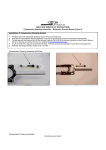
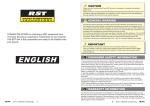
A
B
MANITOU SUSPENSION FORKS
INSTALLATION INSTRUCTIONS
CONGRATULATIONS ON CHOOSING A 2004 MANITOU FORK. This fork
is fully assembled and ready to be installed onto your bicycle. It comes equipped
with a 11/8-inch threadless steerer tube and may be available in
a disc brake only version. A handlebar-mounted reflector must be used for onroad use, which is not included with your fork.
The steerer tube may need to be cut to length to fit your bicycle head tube. If you
are not familiar with this procedure, or do not have the proper tools to cut the
steerer tube, it is recommended that you seek a dealer with a qualified bicycle
mechanic to perform installation.
2004 MANITOU SIX FORK LINE
*Preset from the factory, but changeable.
THE STEERER TUBE AND STANCHIONS (INNER LEGS) ARE
A ONE TIME PRECISION PRESS FIT AT THE FACTORY AND
CANNOT BE REMOVED FROM THE CROWN. REPLACEMENT OF THE ENTIRE
CROWN/STEERER ASSEMBLY MUST BE DONE TO INCREASE STEERER TUBE
LENGTHS OR CHANGE DIAMETERS. REMOVING AND REPLACING THE STEERER
TUBE OR STANCHIONS WILL RESULT IN AN UNSAFE CONDITION AND SHOULD
NEVER BE DONE.
You can also download this manual at www.answerproducts.com.
BREAK-IN
SIX ............................80 OR 100 MM TRAVEL* / COIL & MCU SPRING / SINGLE
CROWN / RA ALUMINUM CASTING
SIX SPORT ................80 OR 100 MM TRAVEL* / COIL & MCU SPRING / SINGLE
CROWN / RA MAGNESIUM CASTING
BICYCLING IS A HAZARDOUS ACTIVITY
THAT REQUIRES THAT THE RIDER STAY IN
CONTROL OF HIS OR HER BICYCLE AT ALL TIMES. READING THIS MANUAL
ENTIRELY AND PROPERLY MAINTAINING YOUR BICYCLE AND SUSPENSION FORK
WILL REDUCE THE POSSIBILITY OF INJURY OR POSSIBLE DEATH. PRIOR TO RIDING YOUR BICYCLE, YOU SHOULD INSPECT YOUR SUSPENSION FORK TO ENSURE
THAT NO DAMAGE HAS OCCURRED DURING THE COURSE OF PREVIOUS RIDING OR
ASSEMBLY. DO NOT RIDE YOUR BICYCLE IF THE FORK SHOWS ANY SIGNS OF
BENDING, CRACKING, CREAKING, LEAKING, OR IF IT IS MISSING ANY OF THE
ORIGINALLY SUPPLIED COMPONENTS. ANY FALL FROM YOUR BICYCLE CAN
RESULT IN SERIOUS INJURY OR EVEN DEATH. FOLLOWING THESE INSTRUCTIONS
CAN HELP YOU REDUCE THE RISK OF BEING INJURED. IF YOU ARE A MODERATE
OR AGGRESSIVE OFF-ROAD RIDER, OR RIDE AT LEAST THREE TIMES A WEEK
OVER ROUGH TERRAIN, ANSWER RECOMMENDS RETURNING YOUR SUSPENSION
FORK EVERY 2 YEARS FOR A THOROUGH INSPECTION AND UPDATE. TAKE YOUR
FORK TO A MANITOU AUTHORIZED DEALER WHO CAN ARRANGE FOR SHIPMENT
TO ANSWER PRODUCTS, OR YOU MAY CALL ANSWER TO HAVE YOUR FORK
SHIPPED DIRECTLY AT (800) 423-0273.
IMPORTANT: The Manitou fork is an off-road fork, and as such, does not
come with proper reflectors for on road use. Have your dealer or mechanic
install proper reflectors to meet the Consumer Product Safety Commission’s
(C.P.S.C.) Requirements for Bicycles if the fork is going to be used on public
roads at any time. If you have questions regarding C.P.S.C. Standards, contact
your dealer.
CONSUMER SAFETY INFORMATION
Never remove or have the steerer tube or stanchions removed from the crown.
The steerer tube and stanchions (inner legs) are press fit at the factory. Press fit
inner legs have higher performance versus bolt-in inner legs, but can not be
pressed out. Pressing them out will permanently damage the crown beyond repair
and render it unsafe for any continued use. Never attempt to thread a threadless
steerer tube. Cutting threads will weaken the steerer tube and cause an unsafe
condition. The only safe thing to do is to obtain the proper crown/steerer from
your dealer, or contact Answer Customer Service at (800) 423-0273. Any other
alteration or modification to your fork should be considered unsafe. Contact
Answer Customer Service prior to modifying your fork in any way for safety information.
Do not use the fork if any parts are broken, bent, cracked, or you suspect may be
damaged. Contact your dealer or Answer Products Customer Service at (800) 4230273 if you have any questions concerning the integrity or condition of your fork.
Answer Products recommends that you periodically inspect your fork for wear and
damage. Inspect the crown, inner legs, outer legs, dropouts and brake arch areas
for cracks or damage.
WARRANTY INFORMATION
Any Answer Products fork found by the factory to be defective in materials and/or
workmanship within one year from the date of purchase (or two years in EU countries) will be repaired or replaced at the option of the manufacturer, free of charge,
when received at the factory, freight prepaid. This warranty does not cover breakage, bending, or damage that may result from crashes or falls. This warranty does
not cover any fork that has been subject to misuse or whose serial number has
been altered, defaced or removed. This warranty does not cover paint damage.
Any modifications made by the user will render the warranty null and void. This
warranty is expressly in lieu of all other warranties, and any implied are limited in
duration to the same duration as the expressed warranty herein. Answer Products
shall not be liable for any incidental or consequential damages.
If for any reason warranty work is necessary, return the fork with original purchase
receipt to the place of purchase. At that time, instructions for repair, return, or
replacement shall be given. Customers in countries other than USA should contact
their dealer or local distributor.
Your new fork is designed to break in during your first few rides (about 20 hours
total riding time). Prior to break-in, you may notice your fork feels tight and slightly notchy. Following the break-in period, your fork will feel much smoother and
will react to bumps much better than when you first put it on your bike. After 20
hours, you may want to recheck adjustments (where applicable) to fine tune the
fork completely.
FORK INSTALLATION
1. Remove the old fork from your bicycle.
2. Measure and cut the steerer tube to fit your bicycle head tube (see WARNING
above). You can use your old fork as a guide for cutting the steerer tube
length.
3. Remove the headset crown race from the old fork.
4. Install headset and fork per headset manufacturer’s instructions.
5. Install the handlebars and stem to the stem and handlebar manufacturer’s
instructions.
6. Install the brakes per the brake manufacturer’s instructions.
7. To install the front wheel adjust the front wheel quick release to clear the secondary dropout safety tabs. Secure wheel per quick release manufacturer’s
instructions.
8. Install the brake cable per brake manufacturer instructions. Ensure that the
front brake cable is properly routed. Make sure the brake line is not crimped
or contacts the tire as the fork moves through its travel.
WHEN INSTALLING THE WHEEL WITH A PROPERLY INFLATED TIRE, CHECK TO MAKE SURE THE FORK ACHIEVES
MINIMUM TIRE CLEARANCE.
1. MEASURE FROM THE HIGHEST POINT ON THE TIRE TO THE BOTTOM OF THE
BRAKE ARCH, SEE FIGURE A. SEE TABLE 1 FOR MINIMUM BRAKE ARCH
CLEARANCE.
2. MEASURE THE TIRE AT MAXIMUM WIDTH, SEE FIGURE B. SEE TABLE 1 FOR
MAXIMUM TIRE WIDTH.
TABLE 1: WHEEL CLEARANCE
MINIMUM BRAKE ARCH CLEARANCE
(See Figure A)
MAXIMUM
TIRE WIDTH
(See Figure B)
5 mm
55 mm
IMPORTANT: Failure to properly route and securely attach the front brake
cable to the fork can cause serious injury or death. This fork should not be used
if any parts appear to be or are damaged. Contact your local dealer or Answer
Products for replacement parts.
INITIAL SET-UP
MEASURING TRAVEL
To determine which travel your fork is in, simply measure the distance from the
top of the seal area on the lowers (or the bottom of the fork boot) to the bottom of
the crown. See Table 2 to determine travel.
TABLE 2: TRAVEL MEASUREMENT
FORK TRAVEL
SEAL TO CROWN
MEASUREMENT
80 mm
Around 110 mm
100 mm
Around 130 mm
MEASURING SAG
You’ll need a tape measure, a pencil, a piece of paper and a helper.
1. Measure the distance from the front axle’s centerline to the bottom of the
upper crown when no one’s sitting on the bike and write this distance down.
(Remember the exact locations of the two points because you’ll need to use
them later.)
2. Have the rider sit on the bike and measure the distance between the same
two points as in step one. It’s important to be in the normal riding position
(weight centered) with your feet on the pedals.
3. Subtract the second measurement from the first. The resulting measurement
is the static sag (See Table 3).
4. The preload adjuster on Manitou forks are located on the top left of the crown
(as you are looking at the fork from the rider’s perspective). Turning the knob
clockwise increases spring preload and decreases sag, while turning the knob
counterclockwise decreases spring preload and increases sag.
5. If adjusting the preload does not provide the proper sag you may require a
new ride kit. Please see recommended ride kits below.
TABLE 3: SAG MEASUREMENT
FORK TRAVEL
SAG
80 mm
12-16 mm
100 mm
18-24 mm
NOTE: Forks with standard dropouts are equipped with dropout safety tabs to
retain the wheel in the fork in the event the quick release comes loose.
2. Wipe the inner legs and clean the fork. Check the entire fork for any obvious
damage. Do not use the fork if any parts are broken, bent, cracked, or you
suspect may be damaged.
3. Check the headset for proper adjustment per headset manufacturer’s instructions.
4. Ensure that the front brake cable is properly routed and check brake adjustment.
If you have any questions regarding your 2004 Manitou suspension fork in the
U.S., contact the Answer Customer Service Department at (800) 423-0273. For
information outside of the U.S., contact your authorized Manitou dealer or distributor.
You can also log on to www.answerproducts.com and download this manual or see
detailed instructions on how to service your suspension fork.
04 SIX SERVICE PART KITS
04 SIX Pre-Load Adjuster Assemblies
85-4810
SIX / SIX Sport Pre-Load Adjuster Assembly
04 SIX Crown Steer Leg Assemblies
85-5366
85-5367
26" SIX Crown/Steer Assembly - Steel
26" SIX Crown/Steer Assembly - Alloy
04 SIX Outer Leg Assemblies
85-5250
85-5368
85-5376
85-5377
85-5228
85-5229
85-5236
85-5233
26" SIX Outer Leg Assembly - Black
26" SIX Outer Leg Assembly - Silver
26" SIX Outer Leg Assembly - Black, No Boss
26" SIX Outer Leg Assembly - Silver, No Boss
26" SIX Sport Outer Leg Assembly - Black
26" SIX Sport Outer Leg Assembly - Silver
26" SIX Sport Outer Leg Assembly - Black, No Boss
26" SIX Sport Outer Leg Assembly - Silver, No Boss
04 SIX Sticker/Boot/Knob/Seal/Bumper Kits
MAINTENANCE
Your fork requires periodic maintenance, cleaning and inspection. This
is because moisture and contamination may build up inside the fork depending on
the severity of riding conditions. To maintain top performance, it is recommended
that the fork be periodically disassembled, cleaned, dried and re-lubricated. You
can download service and tuning instructions on the web at www.answerproducts.com.
SUGGESTED SERVICE INTERVALS FOR SIX FORKS
Short, Sporadic Rides
Long, Frequent Rides
Normal
Conditions
Lube fork as needed
with Prep M grease via
Microlube lubrication
ports (4-6 squirts every
15 rides). Disassemble
fork per Service Manual;
clean and grease every
5-6 months, grease
spring stack as needed.
Lube fork as needed
with Prep M grease via
Microlube lubrication
ports (4-6 squirts every
10 rides). Disassemble
fork per Service Manual;
clean and grease every
4-5 months, grease
spring stack as needed.
Severe
Conditions
Lube fork as needed
with Prep M grease via
Microlube lubrication
ports (4-6 squirts every
10 rides). Disassemble
fork per Service Manual;
clean and grease every
6-8 weeks, grease
spring stack as needed.
Lube fork as needed
with Prep M grease via
Microlube lubrication
ports (4-6 squirts every
10 rides). Disassemble
fork per Service Manual;
clean and grease every
4-6 weeks, grease
spring stack as needed.
IMPORTANT: When lubricating the fork with grease through the Microlube
ports, it is important to note that the grease is being forced between the upper
and lower bushings. If the area is overfilled, the grease may force the upper
bushing and dust seal out. You should only insert grease to the level at which
stiction (stickiness when you compress the fork) is no longer felt.
IMPORTANT: Before every ride you should:
1. Ensure that quick release skewers are properly adjusted and tight per quick
release manufacturer’s instructions.
85-5313
85-5314
85-5388
85-5389
85-5390
85-5395
85-5391
85-5363
SIX Sticker Kit - Silver
SIX Sticker Kit - Black
SIX Sport Sticker Kit - Silver
SIX Sport Sticker Kit - Black
SIX Boot Kit
SIX Knob Kit
SIX Seal Kit
SIX Bumper Kit
04 SIX Ride Kits
85-5030
85-5031
85-5032
SIX Ride Kit - Soft
SIX Ride Kit - Medium
SIX Ride Kit - Firm
Rider Weight Range
130-150 lbs.
150-170 lbs.
170 lbs. & above
04 SIX Compression Rods
85-5315
SIX Compression Rod Assembly, 60 or 75 mm