1
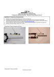
• ENGLISH
MANITOU SUSPENSION FORKS
CONGRATULATIONS ON CHOOSING THE LATEST IN SUSPENSION TECHNOLOGY
AVAILABLE, A 2007 MANITOU FORK. This fork is fully assembled and ready to be
installed onto your bicycle. It comes equipped with either a 1 1/8-inch or a 1.5-inch
steerer tube and may also be available in disc brake only or Hex Lock Thru Axle
versions. A handlebar-mounted reflector must be used for on-road use, which is
not included with your fork.
This manual is designed as a comprehensive guide for all 2007 Manitou fork
models, including TRAVIS, STANCE, GOLD LABEL JUMP SERIES, NIXON, MINUTE,
R7, RELIC, SLIVER, SLATE, AND AXEL. All figures and tables are located at the
back of this manual. This manual can also be downloaded from the
www.answerproducts.com website.
GENERAL CONSUMER SAFETY
INFORMATION
BICYCLING IS A HAZARDOUS ACTIVITY THAT REQUIRES THAT THE RIDER
STAY IN CONTROL OF HIS OR HER BICYCLE AT ALL TIMES. ANY FALL FROM
YOUR BICYCLE CAN RESULT IN SERIOUS INJURY OR EVEN DEATH. READING
THIS MANUAL ENTIRELY AND PROPERLY MAINTAINING YOUR BICYCLE AND
SUSPENSION FORK WILL REDUCE THE POSSIBILITY OF INJURY OR POSSIBLE
DEATH. PRIOR TO EVERY RIDE, YOU SHOULD CLOSELY EXAMINE YOUR
SUSPENSION FORK (AFTER CLEANING) IN BRIGHT SUNLIGHT TO ENSURE
THAT NO DAMAGE HAS OCCURRED DURING THE COURSE OF RIDING,
TRANSPORTING OR AFTER A FALL. PAY PARTICULAR ATTENTION TO THE
CROWN, INNER LEGS, OUTER LEGS, DROPOUTS, BRAKE ARCH AREAS AND
“STRESS POINTS” (SUCH AS WELDS, SEAMS, HOLES AND POINTS OF
CONTACT WITH OTHER PARTS ETC.) DO NOT RIDE YOUR BICYCLE IF THE
FORK SHOWS ANY SIGNS OF BENDING, LEAKING, CRACKING, CREAKING,
SQUEAKING, CLUNKING OR ANY OTHER UNFAMILIAR NOISES, OR IF IT IS
MISSING ANY OF THE ORIGINALLY SUPPLIED COMPONENTS. CONTACT YOUR
DEALER OR ANSWER PRODUCTS CUSTOMER SERVICE AT (800) 423-0273 IF
YOU HAVE ANY QUESTIONS CONCERNING THE FUNCTION, INTEGRITY OR
CONDITION OF YOUR FORK. ANY MODIFICATIONS NOT AUTHORIZED IN THIS
MANUAL SHOULD BE CONSIDERED UNSAFE. IF YOU ARE A MODERATE OR
AGGRESSIVE OFF-ROAD RIDER, OR RIDE AT LEAST THREE TIMES A WEEK
OVER ROUGH TERRAIN, ANSWER RECOMMENDS RETURNING YOUR
SUSPENSION FORK TO ANSWER PRODUCTS EVERY 2 YEARS FOR A THOROUGH
INSPECTION. TAKE YOUR FORK TO A MANITOU AUTHORIZED DEALER WHO CAN
ARRANGE FOR SHIPMENT TO ANSWER PRODUCTS, PHONE # (800) 423-0273.
REFLECTORS
MANITOU FORKS ARE DESIGNED FOR OFF-ROAD USE, AND AS SUCH, THEY DO
NOT COME WITH PROPER REFLECTORS FOR ON-ROAD USE. HAVE YOUR
DEALER OR MECHANIC INSTALL PROPER REFLECTORS TO MEET THE
CONSUMER PRODUCT SAFETY COMMISSION’S (C.P.S.C.) REQUIREMENTS FOR
BICYCLES IF YOUR FORK IS GOING TO BE USED ON PUBLIC ROADS AT ANY
TIME. IF YOU HAVE QUESTIONS REGARDING C.P.S.C. REFLECTORS, PLEASE
CONTACT YOUR DEALER.
IT IS CRITICAL THAT YOU SELECT AND USE THE
SUSPENSION FORK THAT IS APPROPRIATE FOR YOUR
ANTICIPATED RIDING STYLE, THAT YOU USE THE FORK PROPERLY AND
FOLLOW THE WARNINGS CONTAINED IN THE OWNER’S MANUAL, REGARDLESS
OF THE RIDING STYLE. FAILURE TO PROPERLY MATCH THE FORK TO YOUR
FRAME OR RIDING STYLE COULD CAUSE THE FORK TO FAIL, RESULTING IN A
LOSS OF BICYCLE CONTROL AND POSSIBLY SERIOUS INJURY OR DEATH TO
THE RIDER. IN ADDITION, AN IMPROPER COMBINATION OF FRAME AND FORK
FOR THE INTENDED CATEGORY WILL VOID THE FORK'S WARRANTY. VISIT OUR
WEBSITE AT WWW.ANSWERPRODUCTS.COM/ IU FOR MORE DETAILED
INFORMATION AND GUIDANCE ON FORK SELECTION FOR YOUR RIDING STYLE.
YOU SHOULD ONLY ATTACH GENERATORS, RACKS AND DISC BRAKES TO THE
DESIGNATED MOUNTING POINTS PROVIDED ON THE FORKS. NEVER MAKE ANY
MODIFICATION TO YOUR FORK TO ATTACH ANY EQUIPMENT. THERE IS A
HEIGHTENED LEVEL OF VOLUNTARY RISK ASSOCIATED WITH FREERIDING,
DIRT JUMPING AND DOWNHILLING. LARGER STUNTS/JUMPS MEAN MORE
POTENTIAL FOR EQUIPMENT ISSUES OR PROBLEMS AND THE LIKELIHOOD OF
SERIOUS INJURY IS GREATLY INCREASED. LEARN HOW TO PROPERLY RIDE
AROUND OBSTACLES ON THE TRAIL OR ROAD. HITTING OBSTACLES SUCH AS
CURBS, ROCKS, TREES, ROOTS, HOLES OR SIMILAR OBSTACLES STRAIGHT ON
PUTS FORCES ON YOUR FORK IT WAS NOT DESIGNED TO ABSORB.
LANDING IMPROPERLY AFTER A JUMP OR DROP ALSO PUTS FORCES ON
YOUR FORK IT WAS NOT DESIGNED TO ABSORB. YOU SHOULD ONLY PERFORM
JUMPS OR DROPS WHEN A TRANSITION OR DOWN RAMP IS AVAILABLE TO
HELP YOUR BICYCLE AND FORK ABSORB THE IMPACT FORCES GENERATED
DURING THE LANDING, AND BOTH WHEELS SHOULD SMOOTHLY MAKE
CONTACT WITH THE TRANSITION OR DOWN RAMP AT THE SAME TIME. ANY
OTHER TYPE OF LANDING IS DANGEROUS, AS IT COULD OVERLOAD THE
FRAME OR FORK AND RESULT IN A COMPONENT PART FAILURE AND AN
ACCIDENT OR COULD CAUSE YOU TO LOOSE CONTROL OF THE BICYCLE, EVEN
WITHOUT A COMPONENT PART FAILURE. THE STEEPNESS AND LENGTH OF
THE TRANSITION OR DOWN RAMP DEPENDS ON THE HEIGHT FROM WHICH
YOU JUMP OR DROP. EVERY SITUATION IS DIFFERENT FOR EVERY RIDER;
CONSULT WITH AN EXPERIENCED RIDER BEFORE ATTEMPTING ANY JUMP
OR DROP.
FAILURE TO PROPERLY RIDE AROUND OBSTACLES ON THE TRAIL, OR FAILURE
TO PROPERLY LAND AFTER A JUMP OR DROP COULD CAUSE YOUR FORKS TO
FAIL, RESULTING IN A LOSS OF BICYCLE CONTROL AND, POSSIBLY, SERIOUS
INJURY OR DEATH TO THE RIDER. RIDE ONLY IN AREAS SPECIFICALLY
DESIGNATED FOR YOUR RIDING STYLE. DO NOT MISUSE OR ABUSE YOUR
FORKS. LEARN HOW TO RIDE, AND ALWAYS RIDE WITHIN YOUR ABILITIES.
OUT-OF-CONTROL RIDING PUTS THE EQUIVALENT OF YEARS OF HARD USE ON
YOUR FORKS AFTER ONLY A FEW RIDES. SOMETIMES THE DAMAGE IS NOT
OBVIOUS TO THE USER, BUT COULD HAVE FAILED INTERNAL COMPONENTS OR
DAMAGED THE LOAD CARRYING ABILITIES OF THE MATERIALS USED IN THE
CONSTRUCTION OF THE FORK.
ALL SUSPENSION FORKS REQUIRE REGULAR MAINTENANCE AND REPAIR.
THE HARDER YOU RIDE, THE MORE OFTEN YOU MUST INSPECT AND MAINTAIN
YOUR FORKS. IF YOUR FORKS START MAKING ANY STRANGE NOISES,
CLUNKS, CREAKS, CLICKS, OR FEEL “LOOSE” OR DIFFERENT IN ANY WAY,
THEY SHOULD NOT CONTINUE BEING USED, BUT IMMEDIATELY HAVE A
CERTIFIED MANITOU SERVICE CENTER INSPECT AND REPAIR THE FORKS
BEFORE YOU RIDE AGAIN. INSPECT YOUR FORKS REGULARLY TO SEE THAT
THEY ARE NOT BENT, DEFORMED, CRACKED, CHIPPED, NO MATTER HOW
SLIGHT, THEY SHOULD NOT CONTINUE TO BE USED, BUT ALSO IMMEDIATELY
HAVE A CERTIFIED MANITOU SERVICE CENTER INSPECT AND REPAIR THE
FORKS BEFORE BEING USED AGAIN.
IDENTIFY YOUR RIDING STYLE
It is critical that you select and use the suspension fork that is appropriate for
your anticipated riding style, that you use the fork properly and follow all warnings
contained in this owner’s manual regardless of the riding style. See below for
different riding categories. Visit our website at www.answerproducts.com/iu for
more detailed information and guidance on fork selection for your riding style.
Trekking (TK): Trekking is similar to XC riding but not as aggressive as XC. It
involves slower riding, typically on paved and smooth roads, and no riding
obstacles such as rocks, roots, or depressions.
Cross Country (XC): Also called “marathon riding”. Involves riding along hilly trails
where some bumps and smaller obstacles, such as rocks, roots, or depressions,
may be encountered. XC RIDING DOES NOT INCLUDE LARGE JUMPS OR DROPS
(riding off rocks, fallen trees or ledges) from any height. XC forks must only be
used with tires specifically designed for cross country riding. XC forks can be used
with disc, rim or linear pull brakes.
All Mountain (AM): Riding with more emphasis on aggressive XC riding with
larger obstacles and rough terrain. AM RIDING DOES NOT INCLUDE LARGE
JUMPS OR DROPS (riding off rocks, fallen trees or ledges) from any height. These
forks should be used only with disc brakes, as well as frames, wheels and other
components specifically designed for this riding style.
Freeride (FR): This riding style is for skilled riders and involves aggressive slopes,
very rough terrain, large obstacles and moderate jumps. Freeride forks should be
used only with disc brakes as well as frames, wheels and other components
specifically designed for freeriding.
Dirt Jumping (DJ) : Also called “Urban Riding”, this type of riding is only for the
most skilled riders and involves jumping from one mound of dirt to another and
landing smoothly on a downside transition. It also includes riding or jumping over
and around man-made or other concrete structures. These forks should be used
only with frames, wheels and other components specifically designed for this
riding style.
3
Downhill (DH): This discipline is only for professional or highly-skilled riders. It
includes use on relatively high jumps (or “drops”) and negotiating larger obstacles
such as boulders, fallen trees or holes. These forks should be used only with disc
brakes, as well as frames, wheels and other components specifically designed for
this riding style.
INTENDED USES
Visit our website at www.answerproducts.com/iu for more detailed information
and guidance on fork selection for your riding style.
Trekking
Forks for smooth pavement riding.
Cross Country
Intermediate terrain, expeditions and
competition use.
DOWNHILL OR FREESTYLE RIDING OR RACING PLACES EXTREME STRESS ON
BICYCLES AND THEIR COMPONENTS (LIKE IT DOES RIDERS). REPEATED USE
OF A FORK IN DOWNHILL RIDING MAY RESULT IN SUDDEN OR PREMATURE
FAILURE OF A BICYCLE OR COMPONENT RESULTING IN SEVERE INJURIES. IF
YOU PARTICIPATE IN THESE TYPES OF EVENTS, THE LIFETIME OF THE
PRODUCT MAY BE SIGNIFICANTLY SHORTENED DEPENDING UPON THE LEVEL
AND AMOUNT OF RACING. THE “NORMAL WEAR” OF A COMPONENT MAY
DIFFER GREATLY BETWEEN COMPETITIVE AND NON-COMPETITIVE USES,
WHICH IS WHY PROFESSIONAL LEVEL RIDERS OFTEN USE NEW BIKES AND
COMPONENTS EACH SEASON AS WELL AS HAVE THEIR BIKES SERVICED BY
PROFESSIONAL MECHANICS.
REDUCED FORK LIFE
All Mountain
Riding based with more emphasis on
aggressive XC riding with larger obstacles.
Freeride
Forks for the roughest descents, jumps and
drops.
Dirt Jumping
Suspension for big air, manmade stunts and
dual slalom courses.
Downhill
Forks for aggressive riding and pro downhill
racing.
THE LIFE OF THIS FORK WILL BE REDUCED IF (1) YOU USE IT MORE THAN THE
AVERAGE USER, (2) YOU ARE HEAVIER THAN THE AVERAGE RIDER, (3) THE
TERRAIN YOU RIDE ON IS ROUGHER THAN AVERAGE, (4) YOU TEND TO BE
HARDER ON COMPONENTS THAN THE AVERAGE RIDER, (5) IT IS INSTALLED
OR MAINTAINED IMPROPERLY, (6) IT MUST ENDURE MORE ADVERSE ENVIRONMENTAL CONDITIONS THAN THE AVERAGE FORK (I.E. SWEAT, CORROSIVE
MUD, SALTY BEACH AIR ETC.), AND/OR (7) YOU DAMAGE IT IN A CRASH,
JUMP OR THROUGH OTHER ABUSE. THE MORE FACTORS YOU MEET, THE
MORE ITS LIFE WILL BE REDUCED, HOWEVER IT IS IMPOSSIBLE TO SAY
HOW MUCH.
PRESS FIT CROWNS
INTENDED USE
FORK
MODEL
AXEL
•
GOLD LABEL
JUMP SERIES
•
•
•
MINUTE
NIXON
R7
RELIC
SLATE
SLIVER
STANCE
TRAVIS
THE STEERER TUBE (ON BOTH SINGLE AND DOUBLE CROWN FORKS) AND
STANCHIONS (INNER LEGS ON SINGLE CROWN FORKS) ARE PRESS FIT AT THE
FACTORY AND SHOULD NEVER BE REMOVED FROM THE CROWN. PRESSING
THEM OUT WILL PERMANENTLY DAMAGE THE CROWN BEYOND REPAIR AND
RENDER IT UNSAFE FOR ANY CONTINUED USE. NEVER ATTEMPT TO THREAD A
THREADLESS STEERER TUBE. CUTTING THREADS WILL WEAKEN THE STEERER
TUBE AND CAUSE AN UNSAFE CONDITION. OBTAIN THE CORRECT
CROWN/STEERER FROM YOUR DEALER, OR CONTACT ANSWER CUSTOMER
SERVICE AT (800) 423-0273.
•
•
•
•
REPLACEMENT OF THE ENTIRE CROWN/STEERER ASSEMBLY MUST BE DONE
TO INCREASE STEERER TUBE LENGTHS OR CHANGE DIAMETERS. REMOVING
AND REPLACING THE STEERER TUBE WILL RESULT IN AN UNSAFE CONDITION
AND SHOULD NEVER BE DONE.
•
•
•
•
•
INSTALLATION INSTRUCTIONS
•
Please see the website at www.answerproducts.com for additional information.
“DOWNHILL”, “FREESTYLE” OR
COMPETITIVE RIDING
TO RIDE DOWNHILL AT HIGH SPEED OR IN COMPETITION IS TO VOLUNTARILY
ASSUME A VERY HIGH RISK, AND DOWNHILL OR FREESTYLE RIDING CAN
LEAD TO SERIOUS ACCIDENTS. SPEEDS “DOWNHILLING” CAN REACH SPEEDS
SEEN ON MOTORCYCLES WITH SIMILAR HAZARDS AND RISKS. WEAR
APPROPRIATE SAFETY GEAR, INCLUDING A FULL FACE HELMET, FULL FINGER
GLOVES AND BODY ARMOR. HAVE YOUR BICYCLE INSPECTED BY A QUALIFIED
MECHANIC BEFORE EVERY EVENT AND BE SURE IT IS IN PERFECT WORKING
CONDITION. ROUTINE AND THOROUGH MAINTENANCE IS EVEN MORE
CRITICAL THAN WITH A BIKE NOT USED FOR DOWNHILLING OR FREESTYLE
RIDING. CONSULT WITH EXPERT RIDERS AND RACE OFFICIALS ON
CONDITIONS AND EQUIPMENT ADVISABLE AT THE SITE WHERE YOU PLAN TO
RIDE DOWNHILL OR FREESTYLE. SUSPENSION AND DISK BRAKES MAY
INCREASE THE HANDLING CAPABILITIES AND COMFORT OF YOUR BICYCLE
AND MAY ALLOW YOU TO RIDE FASTER, BUT DO NOT CONFUSE THE ENHANCED
CAPABILITIES OF A SUSPENSION BIKE WITH DISK BRAKES WITH YOUR OWN
CAPABILITIES. INCREASING YOUR SKILL WILL TAKE TIME AND PRACTICE.
PROCEED CAREFULLY UNTIL YOU ARE SURE YOU ARE COMPETENT TO HANDLE
THE FULL CAPABILITIES OF YOUR BIKE. WHILE THE RUGGED APPEARANCE OF
MOUNTAIN BIKES AND THESE DISK BRAKES MIGHT SUGGEST THEY ARE
INDESTRUCTIBLE, THEY ARE NOT. CERTAINLY THEY ARE TOUGH AND STURDY.
4
Ensure that the proper steerer tube has been delivered on your fork first. The
steerer tube may need to be cut to length to fit your bicycle head tube. If you
are not familiar with this procedure, or do not have the proper tools to cut the
steerer tube, it is recommended that you seek a dealer with a qualified bicycle
mechanic to perform the installation. When cutting a steering column of a fork
make sure to measure twice before cutting; forks cut too short during
installation are NOT covered by the warranty.
BREAK-IN
Your new fork is designed to break in during your first few rides (about 20 hours
total riding time). Prior to break-in, you may notice your fork feels tight and slightly
notchy. Following the break-in period, your fork will feel much smoother and will
react to bumps much better than when you first put it on your bike. After 20 hours,
you may want to recheck adjustments (where applicable) to fine-tune the fork
completely.
WHENEVER YOU INSTALL ANY NEW COMPONENT ON
YOUR BIKE MAKE SURE YOU THOROUGHLY TRY IT OUT
CLOSE TO HOME (WITH YOUR HELMET) WHERE THERE ARE NO OBSTACLES,
TRAFFIC OR OVERLY CHALLENGING TERRAIN. MAKE SURE EVERYTHING IS
WORKING PROPERLY BEFORE GOING OFF ON A RIDE OR TO A RACE.
FORK INSTALLATION – SINGLE CROWN FORKS
1. Remove the old fork from your bicycle.
2. Measure and cut the steerer tube to fit your bicycle head tube (see CAUTION
above). You can use your old fork as a guide for cutting the steerer tube length.
3. Remove the headset crown race from the old fork and press onto the fork
steerer until the race is seated snugly against the top of the crown per the
headset manufacturer’s instructions.
4. Clean and grease the headset bearings and races per the headset
manufacturer’s instructions.
5. Install the lower bearings (if applicable) on fork crown race per the headset
manufacturer’s instructions.
6. Insert the steerer tube into the head tube of the frame.
7. Install the upper bearings, stem spacers, and stem.
8. Install the stem cap and bolt. Tighten the bolt to headset manufacturer’s
specifications.
9. Install the handlebars and torque the stem pinch screws or stem clamping
system to stem manufacturer’s specifications.
10. Install the brakes and adjust per the brake manufacturer’s instructions.
11. For forks equipped with IT or ClickIt remote lockout levers, install the lever in
an easily accessible position and torque to values indicated in Table 6 at the
back of this manual.
12. For forks with standard dropouts (non through axle), adjust the front wheel
quick release to clear the 0.275” (7 mm) thick secondary catch dropout. The
quick release must be tightened to quick release manufacturer’s specifications
after it is properly seated into the dropout counter bores. Ensure that there is
adequate thread engagement (4 or more threads with the release adjusted to
lock). Refer to your bicycle owners manual on the proper use and adjustment
of the quick release lever. NOTE: 2007 forks with standard dropouts are
equipped with a secondary catch dropout to retain the wheel in the fork in the
event the quick release comes loose.
13. To install the hex axle, simply slip the axle into the dropout, small axle hex
side first into the large dropout hex. Thread in the set bolt into the small hex
side and snug slightly. Push the fork up and down a few times to center the
axle and hub and then tighten all pinch bolts (or levers on the QR Hex Axle
system) to recommendations found in Table 6.
14. Install the brake cable per manufacturer’s instructions.
quick release lever. NOTE: 2007 forks with standard dropouts are equipped
with a secondary catch dropout to retain the wheel in the fork in the event the
quick release comes loose.
13. To install the hex axle, simply slip the axle into the dropout, small axle hex
side first into the large dropout hex. Thread in the set bolt into the small hex
side and snug slightly. Push the fork up and down a few times to center the
axle and hub and then tighten all pinch bolts (or levers on the QR Hex Axle
system) to recommendations found in Table 6.
14. Install the brake cable per manufacturer’s instructions (see WARNING below.)
BRAKE CABLE INSTALLATION
FAILURE TO PROPERLY ROUTE AND SECURELY ATTACH
THE FRONT BRAKE CABLE TO THE FORK CAN CAUSE
SERIOUS INJURY OR DEATH.
Included with your fork is a small black disc brake cable guide (part no. 066455)
that can be attached to the fork to aid in routing the cables to disc brake calipers.
The best method we’ve found is to attach the cable so that it runs down the
outside of the left fork leg. Make sure the brake line is not crimped and does not
touch the tire as the fork moves through its range of travel.
WHEN INSTALLING THE WHEEL WITH A PROPERLY
INFLATED TIRE, CHECK TO MAKE SURE THE FORK
ACHIEVES MINIMUM TIRE CLEARANCE. FAILURE TO CONFORM TO
RECOMMENDED TIRE CLEARANCE SPECIFICATIONS MAY CAUSE THE TIRE TO
STOP SUDDENLY DURING USE CAUSING PERSONAL INJURY OR DEATH.
Measure minimum tire clearance from any point on the profile of the tire upward to
the bottom of the brake arch (see Figure A). Compare to Table 1 for minimum
brake arch clearance. All figures and tables are located at the back of this manual.
Measure the tire at maximum width (see Figure B). Compare with Table 1 for
maximum tire width.
INITIAL SET-UP
MEASURING TRAVEL (the total amount of up and down movement)
To determine how much travel your fork has, simply measure the distance from the
top of the seal on the lowers (or the bottom of the fork boot) to the bottom of the
crown. See Table 2 to determine travel.
FORK INSTALLATION – DUAL CROWN FORKS
1. Remove the old fork from your bicycle.
2. Measure and cut the steerer tube to fit your bicycle head tube. You can use
your old fork as a guide for cutting the steerer tube length. To determine which
upper triple clamp your frame will need see Table 5.
3. Remove the headset crown race from the old fork and press onto the fork
steerer until the race is seated snugly against the top of the crown per the
headset manufacturer’s instructions.
4. Clean and grease the headset bearings and races per the headset
manufacturer’s instructions.
5. Install the lower bearings (if applicable) on fork crown race per the headset
manufacturer’s instructions.
6. Insert the steerer tube into the head tube of the frame.
7. Install the upper bearings, stem spacers, upper triple clamp and stem or
integrated upper handlebar stem clamp.
8. Install the stem cap and bolt. Tighten the bolt to headset manufacturer’s
specifications.
9. Install the handlebars and torque the stem pinch screws or stem clamping
system to stem manufacturer’s specifications. Triple clamp, steerer tube, and
handlebar bolts (integrated crown/stem models only) should be tightened to
recommendations found in Table 6.
10. Install the brakes and adjust per the brake manufacturer’s instructions.
11. Adjust stanchion legs in the upper and lower crowns. The top of the lower
clamp must not be more than 15mm from the step-down point in the upper
stanchion tube leg.
12. For forks with standard dropouts (non through axle), adjust the front wheel
quick release to clear the 0.275” (7 mm) thick secondary catch dropout. The
quick release must be tightened to manufacturer’s specifications after it is
properly seated into the dropout counter bores. Ensure that there is adequate
thread engagement (4 or more threads with the release adjusted to lock).
Refer to your bicycle owners manual on the proper use and adjustment of the
MEASURING SAG (the amount your suspension compresses due to the
weight of your body when in a ntural riding position)
To measure sag, you’ll need a tape measure, a pencil, a piece of paper and a helper.
1. Measure the distance from the front axle’s centerline to the bottom of the
crown when no one is sitting on the bike and write down this measurement.
(Remember the exact locations of the two points because you’ll need to use
them later.)
2. Have the rider sit on the bike and measure the distance between the same two
points as in step one. It is important to be in the normal riding position
(weight centered) with your feet on the pedals.
3. Subtract the second measurement from the first. The resulting measurement
is the static sag (see Table 3).
4. On coil forks with preload adjusters, turning the knob clockwise increases
spring preload and decreases sag, while turning the knob counterclockwise
decreases spring preload and increases sag.
5. On air forks, remove the Schrader air cap located on the top or on the bottom
of the left leg and, using a dedicated shock pump (Manitou part #85-4162),
inflate the fork with the desired pressure. Be aware that sometimes air
systems lose a small amount of pressure when the pump is removed, so you
may want to check exactly how much your pump loses by reinstalling it after
you have set and checked the pressure.
When setting sag on forks featuring IT (Infinite Travel) technology, see
“ADJUSTING MAIN SPRING AIR PRESSURE” below.
6. If adjusting the preload or air pressure does not provide the proper sag, you
may require a new ride kit. Please see recommended ride kits below.
5
COMPRESSION DAMPING ADJUSTMENT – INTRINSIC DAMPING™
COMPRESSION DAMPING ADJUSTMENTS – PLATFORM PLUS™
Forks equipped with the Intrinsic damping system are designed to be extremely
supple in the initial 50% of their travel while still maintaining the bottomless feeling
inherent with a traditional SPV damped fork. Turning the red knob at the top of the
right fork leg counterclockwise delays Intrinsic’s anti-bottoming properties until the
fork is deeper in the stroke. Turning the red knob clockwise will create a more
progressive damping effect and make the suspension firmer from mid-stroke to
bottom-out.
For forks equipped with the Platform Plus damping system, a simple turn of the
red knob located on top of the right leg is all that is needed to increase platform
effect. Turning the knob clockwise (as you are looking from a rider’s position)
increases the amount of platform and bobbing resistance, while turning the knob
counterclockwise decreases platform for a more active feel.
PLATFORM ADJUSTMENT – SNAP VALVE SPV™
and SPV EVOLVE™
Forks equipped with the FFD damper do not have external compression damping
adjustments.
With Snap Valve SPV (“Stable Platform Valve” damping) and SPV Evolve damping
systems, your suspension’s compression damping characteristics, platform, and
position sensitivity can be set with an SPV pump (Manitou part #85-4163). For
proper function of your SPV damping system follow this procedure:
1. Start by removing the red SPV air cap located on the top of the right fork leg,
as you are looking at the fork from the rider’s position. Using a dedicated SPV
pump (Manitou Part #85-4163), inflate the fork to the pressure recommended
in Table 7.
2. Check sag per procedure above.
3. Adjust SPV pressure. More pressure will create more compression damping,
hold the bike up more and pedal better. Less pressure will create less
compression damping, allow more sag, and be more responsive and supple.
NOTE: Snap Valve SPV forks will have a much higher platform for a given
pressure setting since it is a cross country/marathon specific damper. For the
Snap Valve SPV system, we recommend starting with 70 psi (4.8 bar) in both
the main spring and the Snap Valve damper leg. Ideal setup with this system
will have roughly equal pressures in both the main spring and the Snap Valve
damper sides.
REBOUND DAMPING ADJUSTMENT
DO NOT RUN SPV PRESSURE BELOW 30 PSI (2.04 BAR).
PRESSURES BELOW 30 PSI (2.04 BAR) WILL RESULT IN
A LACK OF BOTH COMPRESSION AND REBOUND DAMPING AS WELL AS A
KNOCKING SENSATION IN THE FORK. MAXIMUM SPV PRESSURE IS 150 PSI
(10.2 BAR).
4. Adjust SPV volume (SPV Evolve forks only). With a 16 mm socket wrench or
the SPV 16 mm volume adjust socket (part #85-3007), you can adjust the air
volume in your SPV Evolve suspension. The volume adjust hex is colored red
and is located on top of the right leg. Turning the volume adjuster inwards will
create a more progressive damping effect and make the suspension firmer
from mid-stroke to bottom-out. Turning the volume adjuster outwards will
make the suspension more linear in compression damping and have a
softer finish.
COMPRESSION DAMPING ADJUSTMENT – TPC+™
For forks equipped with TPC+, a simple turn of the knob located on top of the right
leg is all that is needed to add compression damping. Turning the knob clockwise
(as you are looking from a rider’s position) increases compression damping, while
turning the knob counterclockwise decreases compression damping. Some forks
featuring TPC+ may not have external compression adjustments. Please consult
the service manual (located at www.answerproducts.com) for further instructions
on how to adjust these forks.
COMPRESSION DAMPING ADJUSTMENT – TPC LOCKOUT™
and CLICKIT REMOTE LOCKOUT™
For forks equipped with TPC with lockout, a simple turn of the knob located on top
of the right leg is all that is needed to add compression damping and activate the
lockout. Turning the knob clockwise (as you are looking from a rider’s position)
increases compression damping and activates the lockout, while turning the knob
counterclockwise decreases compression damping and deactivates the lockout.
The last 1/4 turn of the knob activates the lockout, while the initial part of the
knob’s travel increases or decreases compression damping.
TPC Lockout forks can be upgraded to the ClickIt remote lockout system. ClickIt
remote lockout is an “on or off” lockout system designed to be mounted on the
handlebar for easier lockout actuation.
It is important to note that the ClickIt remote lockout system requires the rider to
un-weight the fork before lockout disengagement. When you release the fork from a
lockout position, the lockout will not disengage until after the next bump encounter
or until the fork is un-weighted.
6
COMPRESSION DAMPING ADJUSTMENTS – FLUID FLOW
DAMPING (FFD)™
Rebound adjusters on Manitou forks are located on the bottom of the right fork
leg. Turning the knob clockwise (as you are looking at the fork from the bottom)
increases rebound damping, while turning the knob counterclockwise decreases
rebound damping.
ADJUSTING MAIN SPRING AIR PRESSURE
Remove the air cap located on either the top or bottom of the left fork leg and,
using a dedicated air pump (Manitou Part #85-4162), inflate the fork with the
desired pressure. Be aware that sometimes air systems lose a small amount of
pressure when the pump is removed, so you may want to check exactly how much
your pump loses by reinstalling it after you have set and checked pressure.
Forks with Infinite Travel (IT)™ adjustment have their main air spring adjuster at
the bottom of the left fork leg. When pressurizing the main spring with IT, you will
need to turn your fork /bike upside down (to keep from getting oil inside your air
pump), pump to the desired setting, and with the pump still installed, depress the
handlebar mounted travel adjuster. This will equalize the two chambers in the fork
leg and cause the pressure reading on your pump to drop. Repeat the procedure
until the pressure reading on the shock pump, with the handlebar-mounted travel
adjuster depressed, reaches the desired pressure. Maximum main spring air
pressure is 300 psi (20.4 bar). Consult the website for further instructions if
necessary.
INFINITE TRAVEL (IT)™ TRAVEL ADJUSTMENT
Forks with IT adjustment can be set to anywhere in their travel range by
depressing the bar-mounted travel adjust lever, compressing the fork to the desired
travel, then releasing the bar-mounted lever. These forks can be set anywhere
within their travel range while maintaining a constant spring rate. Changing travel
while riding IT forks requires the rider to be proficient with the IT system, as
lengthening travel will require you to un-weight the front end of the bike. For sag
and air pressure adjustments, please see above recommendations.
RAPID TRAVEL WIND DOWN™
To change the travel with Rapid Travel Wind Down, just turn the knob located at
the top of the left leg (from a rider’s perspective) clockwise for shorter travel and
counterclockwise for longer travel. Use the dial indicator to determine the travel you
are in. The number that is at the back of the crown indicates your current travel
setting. Do not attempt to activate this travel adjust feature while riding.
STAGE 2™ SPRING RATE ADJUSTMENT SYSTEM
The Stage 2 spring rate adjustment system is featured on 2007 MINUTE COMP
forks only. Much more than just a preload, the Stage 2 adjuster allows the rider to
alter the spring rate from a medium to a firm setting. Just turn the knob located at
the top of the left leg (from a rider’s perspective) clockwise for a firmer rate and
counterclockwise for a lighter rate.
MAINTENANCE
Your fork requires periodic maintenance, cleaning and inspection. This is because
moisture and contamination may build up inside the fork depending on the severity
of riding conditions. To maintain top performance, it is recommended that the fork
be periodically disassembled, cleaned, dried and re-lubricated. You can download
service and tuning instructions on the web at www.answerproducts.com.
SUGGESTED SERVICE INTERVALS FOR
ALL MANITOU SUSPENSION FORKS
NORMAL CONDITIONS
Short, Sporadic Rides
Long, Frequent Rides
Disassemble fork per Service Manual.
Clean out casting and replace Semi
Bath oil every 6 months. Service FFD,
TPC, TPC+, SPV Evolve, Snap Valve
SPV, and Intrinsic damping systems
by changing the damper oil every year.
Grease spring stack as needed. On air
fork models, check the oil level sitting
on top of the air piston every 2
months per directions found on
www.answerproducts.com.
Disassemble fork per Service Manual.
Clean out casting and replace Semi
Bath oil every 4 months. Service FFD,
TPC, TPC+, SPV Evolve, Snap Valve
SPV, and Intrinsic damping systems
by changing the damper oil every year.
Grease spring stack as needed. On air
fork models, check the oil level sitting
on top of the air piston every 6 weeks
per directions found on
www.answerproducts.com.
SEVERE CONDITIONS
Short, Sporadic Rides
Long, Frequent Rides
Disassemble fork per Service Manual.
Clean out casting and replace Semi
Bath oil every 4 months. Service FFD,
TPC, TPC+, SPV Evolve, Snap Valve
SPV, and Intrinsic damping systems
by changing the damper oil every year.
Grease spring stack as needed. On air
fork models, check the oil level sitting
on top of the air piston every 6 weeks
per directions found on
www.answerproducts.com.
Disassemble fork per Service Manual.
Clean out casting and replace Semi
Bath oil every 3 months. Service FFD,
TPC, TPC+, SPV Evolve, Snap Valve
SPV, and Intrinsic damping systems
by changing the damper oil every year.
Grease spring stack as needed. On air
fork models, check the oil level sitting
on top of the air piston every 4 weeks
per directions found on
www.answerproducts.com.
BEFORE EVERY RIDE YOU SHOULD:
1. Ensure that the quick release skewers are properly adjusted and tight.
Refer to your bicycle owners manual on the proper use and adjustment of
the quick release lever and for other pre ride checks. NOTE: 2007 forks
with standard dropouts are equipped with a secondary catch dropout to
retain the wheel in the fork in the event the quick release comes loose.
2. Ensure that all bolts are tightened to the appropriate torque
recommendations by the parts’ respective manufacturer.
3. Wipe the inner legs and clean the fork. Check the entire fork for any
obvious damage.
4. Check the headset for proper adjustment. To check for a loose front
headset apply the front brake with both wheels on level pavement and
push the bike forwards and backwards rapidly to see if you hear the
headset rattling. If it is then it is too loose. Follow headset manufacturer’s
instructions to tighten.
5. Ensure that the front brake cable is properly routed and check brake
adjustment. Follow brake manufacturer’s instructions.
TABLE 1 – WHEEL CLEARANCE
FORK MODEL
MINIMUM BRAKE ARCH
CLEARANCE
MAXIMUM
TIRE WIDTH
(See Figure A)
(See Figure B)
AXEL
8.5 mm
SLATE
8.5 mm
60 mm
RELIC
12.5 mm
60 mm
SLIVER
60 mm
9 mm
55 mm
R7
10 mm
60 mm
MINUTE
9.5 mm
63 mm
17 mm
65 mm
NIXON
GOLD LABEL
14.2 mm
65 mm
STANCE
12 mm
65 mm
TRAVIS
11.4 mm
70 mm
TABLE 2 – TRAVEL MEASUREMENT
NOTE: Measurements taken on outside of the stanchion leg.
MODEL
FORK
TRAVEL
TOP OF BOOT TO CROWN
MEASUREMENT
AXEL
80 mm
AXEL
100 mm
120 mm
AXEL
120 mm
140 mm
MODEL
FORK
TRAVEL
100 mm
SEAL TO CROWN
MEASUREMENT
SLATE
80 mm
90 mm
SLATE
100 mm
110 mm
SLATE
130 mm
140 mm
RELIC
80 mm
90 mm
RELIC
100 mm
110 mm
RELIC
130 mm
139 mm
SLIVER
80 mm
92 mm
SLIVER
100 mm
112 mm
R7
80 mm
103 mm
R7
100 mm
123 mm
MINUTE
100 mm
124 mm
MINUTE
120 mm
144 mm
MINUTE
140 mm
161 mm
167 mm
NIXON
145 mm
CHECKING OIL LEVEL
NIXON
160 mm
189 mm
SETTING THE PROPER OIL LEVEL IN YOUR DAMPED
SUSPENSION FORK IS CRITICAL. THE DAMPING IS
LOCATED IN THE RIGHT LEG OF YOUR FORK. NOT ENOUGH OIL WILL ALLOW
FOAMING AND REDUCE THE PERFORMANCE. TOO MUCH OIL WILL RESTRICT
TRAVEL AND MAY CAUSE DAMAGE TO THE SYSTEM AND CREATE AN UNSAFE
RIDING CONDITION. FINISH READING THIS ENTIRE SECTION PRIOR TO
ALTERING THE OIL LEVEL.
To check the oil level, remove the compression assembly located in the right leg
(as you are looking at the fork from the rider’s position). Leave the spring stack in
place to keep the fork fully extended. Use a tape measure or “dip stick” to measure
from the top of the fork crown down to where the oil sits (Figure C). See Table 4 for
the correct oil level for your fork model.
NOTE: Use SAE 5WT suspension fork oil from high quality manufacturers such as
Motorex or Maxima.
If you have any questions regarding your 2007 Manitou suspension fork in the
USA, contact the Answer Customer Service Department at (800) 423-0273. For
information outside of the USA, contact your authorized Manitou dealer or
distributor. You can also log on to www.answerproducts.com and download this
manual or see detailed instructions on how to service your suspension fork.
GOLD LABEL JUMP
80 mm
110 mm
GOLD LABEL JUMP
100 mm
130 mm
STANCE (single crown)
80 mm
109 mm
STANCE (single crown)
100 mm
129 mm
STANCE (single crown)
130 mm
154 mm
STANCE (single crown)
150 mm
181 mm
STANCE (single crown)
170 mm
201 mm
STANCE (dual crown)
150 mm
193 mm
STANCE (dual crown)
170 mm
213 mm
TRAVIS (single crown)
150 mm
162 mm
TRAVIS (single crown)
180 mm
192 mm
TRAVIS (single crown)
203 mm
215 mm
TRAVIS (dual crown)
180 mm
223 mm
TRAVIS (dual crown)
203 mm
246 mm
7
TABLE 3 – SAG MEASUREMENT
FORK TRAVEL
TABLE 6 – RECOMMENDED TORQUE SPECIFICATIONS
SAG
TORQUE SPECIFICATIONS – Nm (in-lbs)
12 - 16 mm
TRAVIS INTEGRATED STEM
5.7 - 6.8 Nm (50 - 60 in-lb)
100 mm
15 - 20 mm
DUAL CROWN CLAMPS
11.3 - 12.4 Nm (100 - 110 in-lb)
120 mm
18 - 30 mm
HEX AXLE BOLTS
3.4 - 4.5 Nm (30 - 40 in-lb)
130 mm
26 - 33 mm
QUICK RELEASE HEX AXLE
140 mm
27 - 36 mm
145 mm
29 - 37 mm
150 mm
30 - 45 mm
160 mm
32 - 47 mm
QUICK RELEASE THROUGH AXLE
TORQUE PROCEDURE:
A) Install axle.
B) Put lever in closed position.
C) Torque lever bolts to 3.4 - 4.5 Nm
(30 - 40 in-lb).
170 mm
34 - 50 mm
180 mm
36 - 54 mm
203 mm
40 - 60 mm
TABLE 4 – OIL LEVEL HEIGHT
FORK MODEL
* AXEL
* SLATE
* SLIVER
* RELIC
R7 COMP, FFD
R7 ELITE, Platform+
* R7 SUPER, TPC/Lockout
R7 PLATINUM, Snap Valve SPV, 80 mm
R7 PLATINUM, Snap Valve SPV, 100 mm
* MINUTE
NIXON
GOLD LABEL JUMP SERIES
STANCE (Single Crown)
STANCE (Double Crown)
TRAVIS
Levels for Noted Options:
* Remote Lockout
OIL LEVEL
110 - 125 mm
110 - 125 mm
110 - 125 mm
115 - 125 mm
110 - 125 mm
75 - 85 mm
115 - 125 mm
110 - 120 mm
90 - 100 mm
See Service Manual on Web
See Service Manual on Web
110 - 115 mm
85 - 95 mm
220 - 240 mm
See Service Manual on Web
105 - 115 mm
TABLE 5 – DUAL CROWN SIZING
CUP-TO-CUP MEASUREMENT*
DUAL CROWN SIZE
STANCE KINGPIN
130 - 160 mm
Small (flat upper crown)
155 - 185 mm
Large (drop upper crown)
TRAVIS
130 - 169 mm
Small (flat upper crown)
150 - 185 mm
Large (drop upper crown)
*Cup-to-cup measurement is the distance from the bottom of the lower headset
cup to the top of the upper headset cup.
8
ITEM
80 mm
AXLE BOLT:
D) Torque: Hand tight.
REMOTE HANDLEBAR CLAMP
0.45 - 0.68 Nm (4 - 6 in-lb)
REMOTE LEVER CABLE CLAMP SCREW
0.34 - 0.56 Nm (3 - 5 in-lb)
TABLE 7 – SPV PRESSURE RECOMMENDATIONS
SPV PRESSURE:
Pressurize the red Schrader valve to the following percentage of your
body weight:
Pounds and PSI
50-70% of your body weight (between minimum 40 and maximum 175 psi)
for shocks
30-40% of your body weight (between minimum 40 and maximum 175 psi)
for forks with SPV or SPV Evolve
35-50% of your body weight (between minimum 40 and maximum 175 psi)
for forks featuring Snap Valve SPV
Kg and Bar
7.5-10.5% of your body weight (between minimum 2.75 and maximum
12 bar) for shocks
4.5-6.5% of your body weight (between minimum 2.75 and maximum
12 bar) for forks with SPV or SPV Evolve
5.25-7.5% of your body weight (between minimum 2.75 and maximum
12 bar) for forks featuring Snap Valve SPV
WORLDWIDE LIMITED WARRANTY
Answer Products (producer/manufacturer) warrants to the original retail
purchaser (“you”) that the Answer Products product for which they received this
warranty is free from defects in material and workmanship for ONE year (two
years in European Union countries) from the date of original retail purchase. This
warranty is not transferable to a subsequent purchaser. Answer Products’ sole
obligation under this warranty is to repair or replace the product, at Answer
Products’ option. Answer Products must be notified in writing of any claim under
this warranty within 60 days of any claimed lack of conformity of the product.
purchased the item or another authorized Answer Products retailer, or authorized
Answer Products distributor.
Any postage, insurance or other shipping costs incurred in sending your Answer
Products product for service is your responsibility. Answer Products will not be
responsible for products lost or damaged in shipping.
For products purchased in countries other than the United States please contact
Answer Products’ authorized distributor or retailer in the country where the
product was purchased. They can be found on our website at
www.answerproducts.com.
Warranty Limitations
Warranty Exclusions
The duration of any implied warranty or condition, of merchantability, fitness for a
particular purpose, or otherwise, on this product shall be limited to the duration
of the express warranty set forth above. In no event shall Answer Products be
liable for any loss, inconvenience or damage, whether direct, incidental,
consequential or otherwise, resulting from breach of any express or implied
warranty or condition, of merchantability, fitness for a particular purpose, or
otherwise with respect to this product, except as set forth herein. Some states or
countries do not allow limitation on how long an implied warranty lasts and some
do not allow exclusions or limitations of incidental or consequential damages, so
the above limitations or exclusions may not apply to you. This warranty gives you
specific legal rights, and you may also have other rights, which may vary, from
location to location. This warranty will be interpreted pursuant to the laws of the
United States. The original English language version/meaning of this warranty
controls over all translations and Answer Products is not responsible for any
errors in translation of this warranty or any product instructions. This warranty is
not intended to confer any additional legal, jurisdictional or warranty rights to you
other than those set forth herein or required by law. If any portion of this
warranty is held to be invalid or unenforceable for any reason, such finding will
not invalidate any other provision. For products purchased in countries other than
the United States please contact Answer Products’ authorized distributor or
retailer in that respective country.
Retailers and sellers of Answer Products products are not authorized to modify
this warranty in any way. It is your responsibility to regularly examine the product
to determine the need for normal service or replacement. This warranty does not
cover the following:
Warranty Service
To obtain service under this warranty you must bring or send your Answer
Products product, together with this warranty, the retail seller's original receipt or
other satisfactory proof of the date of purchase to the retailer where you
• Products that have been modified, neglected or poorly maintained, used for
commercial purposes, misused or abused or involved in accidents.
• Damage occurring during shipment of the products (such claims must be
presented directly to the shipper).
• Products whose serial number has been altered, defaced or removed.
• Damage to products resulting from improper assembly or repair, the use or
installation of parts or accessories not compatible with the original intended use
of the product, or the failure to follow the product warnings and usage
instructions.
• Damage or deterioration to the surface finish, paint, aesthetics or appearance of
the product.
• The labor required to remove and/or re-fit and re-adjust the item covered by
this warranty.
• Normal wear to the product.
• Any products for which the consumer does not follow the warranty procedures
outlined above.
For the current version of this warranty please visit our website at
www.answerproducts.com.
9
.B.
.A.
.C.
71
Answer Products, Inc.
28209 Avenue Stanford
Valencia, California 91355
Phone 1-661-257-4411 or toll free 1-800-423-0273
www.answerproducts.com
[email protected]
© Copyright Answer Products, Inc. April 2006