1
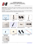
Unity-Series
Component Systems
Installation & Reference Manual
1240 Oak Industrial Lane
Cumming Georgia 30041
United States
(T) +1 770 888 8200
(F) +1 888 886 4605
hybrid-audio.com
Contents
01
02
03
04
05
2
© Hybrid Audio Technologies • Cumming, GA • 770.888.8200
Welcome & Introduction
Pages 4-5
Component Specific Information
Pages 6-17
Midbass, Tweeter, & Crossover
Attributes, Specifications, Parameters,
and Mechanical Drawings
Getting Started
Pages 18-23
Basic System Installation
Moving Forward
Pages 24-31
Advanced System Installation,
Lessons Learned, Mounting Baffle
Considerations, and Acoustic
Treatment
Warranty
Page 32-33
© Hybrid Audio Technologies • Cumming, GA • 770.888.8200
3
Congratulations
on your Unity
Component
System purchase,
and welcome
to the world of
Hybrid Audio
Technologies!
Welcome and Introduction
by Scott Buwalda - Founder
We realize that
you have a choice
in loudspeakers,
and are thrilled
that you have
chosen the Unity
series component
systems. For more
information about
Hybrid Audio
Technologies,
our philosophies
regarding
high-end mobile
audio, to learn
more about
our lifetime
guaranteed value
program, and
for information
about our other
products, please
visit us at:
hybrid-audio.com
Speaker development is our passion!
When installed and set-up properly,
the Unity Component System you have
purchased will make a remarkable
improvement in the sound quality
of virtually any mobile audio sound
system and give years of superior
performance.
With the publication of this manual, it
is our goal to assist the “do it yourself”
enthusiast and professional installer
alike in getting the highest level of
performance out of Unity Component
Systems using straight-forward
installation advice.
Thank you, and happy listening!
4
© Hybrid Audio Technologies • Cumming, GA • 770.888.8200
© Hybrid Audio Technologies • Cumming, GA • 770.888.8200
5
Unity
Component
Systems
Your Unity system
contains speaker drivers
and passive crossover
networks that were
developed and assembled
with a significant
effort in research and
development, materials
science engineering,
an exhaustive level of
sampling and prototyping,
real-world testing, and
obsessive attention to
detail. The specifications
and parameters of your
Unity component system is
detailed on these pages.
6
Midbass Attributes
Unity U5 & U6
Frame
Cast ABS plastic. The basket is a high-quality cast
ABS design, which plays a critical role in aligning the
voice coil in the magnetic circuit. Additionally, the
cast ABS frame allows for better clamping strength
verses typical stamped steel frames, and ensures
that the voice coil remains centered in the former.
The frame is a shared technology with the Imagine
series coaxial and convertible component sets,
and allow for immediate upgrade potential due
to identical size footprint, mounting depth, bolt
circle diameter, and motor diameter as the Imagine
convertible coaxial systems.
Cone and Dust Cap
Pressed paper with water proof treatment. It is
widely acknowledged that pressed paper cones
are the best marriage of lightness, stiffness, and
ability of the cone to damp unwanted cone and
edge modes and resonances (read: distortion). The
paper cone, known for its excellent sonic attributes,
is water proof, thanks to a polymer developed
exclusive and proprietarily by Hybrid Audio
Technologies. The treatment does not change the
look and parameters of the driver like old-fashioned
“glossy” polymers which added an appreciable
amount of moving mass and significantly colored
the sound. No, the Unity cones look like any
“normal” paper cone, but in reality are likely the
© Hybrid Audio Technologies • Cumming, GA • 770.888.8200
only high-performance water proof paper cone
car audio speaker systems on the market. The
treatment protects the cone from periodic drips
(such as inside a door panel), as well as accidental
splashes to the front of the cone. Likewise, the
paper dustcap is also treated for water resistance.
The cone is a shared technology with the Imagine
series coaxial and convertible component sets. On
the hybrid-audio.com website, we have hosted a
video of an actual water-proof demonstration of
the Imagine I61-2, which uses the same cone as the
Unity series, where we pour two liters of water over
the driver, and then connect it to a musical source.
That video may be viewed at: http://hybrid-audio.
com/imagine/
Surround
Inverted high-loss rubber surround. The inverted
high-loss rubber surround (in concert with the
spider, detailed below), helps to provide the
compliance and “restorative force” needed for
the Unity drivers to play effectively into the lower
midbass, and even upper subbass frequencies
(depending on in-car cabin gain and other factors).
You’ll also know a Hybrid Audio midrange and
midbass design by its inverted surround; this
design feature allows for the use of a smaller height
grille, better clearance with OEM panels, and more
flexibility in mounting options. The surround is a
shared technology with the Imagine series coaxial
and convertible component sets.
Spider
Phenolic fabric and tinned tinsel leads. The spider
is the brownish/yellow corrugated (rippled) fabric
that attaches the cone and voice coil. The spider for
the Unity designs was the subject of a considerable
amount of our research and development. The
spider is a phenolic symmetrically-rolled fabric
which provides excellent restorative force during
excursion. The spider is vented courteous of the
speaker frame; a design element not typically found
in this price range of speaker system. The spider
venting increases the thermal power handling
of the Unity midbass driver. The tinsel leads are
connected to real epoxy PCB, not flimsy cardboard.
The spider, tinsel leads, and terminals are shared
technologies with the Imagine series coaxial and
convertible component sets.
Voice Coil and Motor System
The voice coil used in the Unity midbass is a
2-layer aluminized copper wire coils on a round
former. An “overhung” voice coil was selected to
improve sensitivity while still keeping distortion to
a minimum. The voice coil and motor system are
shared technologies with the Imagine series coaxial
and convertible component sets.
Continued on following page...
© Hybrid Audio Technologies • Cumming, GA • 770.888.8200
7
Unity
Component
Systems
Your Unity system
contains speaker drivers
and passive crossover
networks that were
developed and assembled
with a significant
effort in research and
development, materials
science engineering,
an exhaustive level of
sampling and prototyping,
real-world testing, and
obsessive attention to
detail. The specifications
and parameters of your
Unity component system is
detailed on these pages.
Tweeter Attributes
Unity U1
Dome
Small diameter impregnated silk textile dome
with high-loss rubber suspension. The U1 is a
shared technology with the high-end Clarus
C1 tweeter, boasting has an impregnated fine
cloth silk dome diaphragm for a linear, smooth
sound, with a high-loss rubber suspension
to damp edge modes and resonances. The
dome is of extremely low mass and is much
less susceptible to mechanical deformation
than other designs, and yet yields a smooth
response over the extent of its range. At Hybrid
Audio Technologies, we feel larger diaphragm
tweeters sound heavy and unremarkable,
lack detail in the upper treble frequencies,
have undesirable polar response, and are
difficult to install. Additionally, we find metal
dome tweeters to be harsh, brittle, and sound
unrealistic. As a small diameter, soft-dome
tweeter, the U1 is the antithesis of large
diaphragm and metal-dome tweeters, for the
effective and convincing reproduction of treble
frequencies.
Voice Coil and Motor System
20mm complimentary design. The motor
assembly is “conventional dynamic”, with a
compact neodymium magnet structure to
8
© Hybrid Audio Technologies • Cumming, GA • 770.888.8200
ensure a small footprint size and shallow
depth. A perforated grille protects the dome.
The voice coil is ferrofluid cooled and damped,
and the tweeter housing consists of extruded
plastic with three different mounting options
in component set mode, giving the end-user
flexibility in not only placement of the U1 but
also in physical installation.
Network Components
Audiophile grade. The U51-2 and U61-2
passive crossover networks incorporate a
super high quality and low tolerance metalized
polypropylene film capacitor for highpass, and
a low-tolerance quality metalized electrolytic
capacitor for low pass, in concert with air-core
inductors, and low tolerance non-inductive
resistors. No output level switches were
used in the passive crossover design because
switches add a resistive effect and are typically
of extremely low quality. Additionally, “jumper
Unity U2x
pins” add an unnecessary pair of splices in
the signal path to the tweeter, and were not
Alignment
included in our design either. Rather, all tweeter
Second order L/R (12 dB/octave) filters for low
level adjustments are done on the board level
pass (U5 or U6) and high pass (U1). The U51-2
with dedicated non-inductive resistors; tweeter
2-way passive crossover network includes
attenuation is accomplished by selecting the
a unity low pass and high pass crossover
appropriate output (-3 dB, 0 dB, or +3 dB)
frequency of 5,700 Hz at 12 dB/octave. The
on the passive crossover circuit board. The
U61-2 2-way passive crossover network includes components selected are complimentary and
a unity low pass and high pass crossover
ensure no notable signal degradation between
frequency of 5,200 Hz at 12 dB/octave. The use the input and output side of the crossovers. The
of 12 dB/octave filters on both low pass and
network componentry, design, circuitry, and
high pass, often not found in speakers in this
polyethylene case with transparent cover are
price range, minimizes phase-related distortion shared technologies to the Clarus series, and
typical of crossovers with mismatched orders,
the Clarus C2x crossover design.
and ensures phase-coherent imaging and
staging. The alignment topology is a shared
technology to the high-end Clarus C2x
crossover design and features asymmetricallyaligned network components.
Crossover Attributes
© Hybrid Audio Technologies • Cumming, GA • 770.888.8200
9
Unity
Component
Systems
Specifications &
Parameters
U51-2
System
U61-2
System
U5
Midbass
U6
Midbass
Overall Diameter
Φ150 mm
Φ165 mm
Mounting Depth
68 mm
68.8 mm
Bolt Circle Diameter
Φ139 mm
Φ156 mm
Mounting Hole
Φ 123 mm
Φ140 mm
65 Hz
60 Hz
Recommended Minimum Highpass
Crossover Frequency (fourth order)
Continuous Power Handling
(Pnom Rated Power Input • No crossover)
100 watts
100 watts
(25 watts)
(40 watts)
Peak Power Handling
(Pmax Rated Power Input • No Crossover)
230 watts
230 watts
(50 watts)
(80 watts)
Recommended Power Range
20-150 watts
20-150 watts
Frequency Response (+/- 3dB)
55 Hz - 22 kHz
50 Hz - 22 kHz
60 Hz - 8 kHz
55 Hz - 6.5 kHz
91.8 dB
93.2 dB
Mms
9.48 g
10.5 g
Cms
416 μM/N
403 μM/N
5.5
5.5
25.5 mm
25.5 mm
DC Resistance
3.4 Ω
3.4 Ω
Fs (Free Air)
80 Hz
75 Hz
Qms
3.227
4.506
Qes
0.553
0.679
Qts
0.472
0.59
Xmax (Two Way)
10mm
12mm
Vas
5.2 L
8.1 L
Sd
9.331 mm2
11.882 mm2
Efficiency 2.83V/1 meter
BL (T*m)
Voice Coil Diameter
Nominal Impedance
10
4Ω
4Ω
© Hybrid Audio Technologies • Cumming, GA • 770.888.8200
† Typically, in-car response including vehicular “cabin gain”, or the gain expected
with midbass installed in the vehicle, will result in an extended midbass and
upper subbass response. This is a result of these frequencies being below the
lowest resonance in the vehicle (typically around 50-125 Hz in most vehicles,
described in more detail on page 23). In more practical terms, install the Unity
midbass into your vehicle and you will see a dramatic improvement in midbass
and upper subbass output, much more so than just simply listening to the Unity
in a large room, or worse yet, “free air” (we don’t recommend even trying the
Unity speakers in “free air” without some form of enclosure or infinite baffle for
the midbass).
Thiele/Small Parameter Discussion for Unity Midbass
Speakers
The mechanical and electrical parameters of the Unity midbass speakers
are amenable to a variety of different installations and speaker locations.
The high Qms (Q factor of mechanical system) and Qts (Q factor of total
system), coupled with the driver’s Fs (resonance frequency) allow it to be
used in an “infinite baffle” configuration. In more practical terms, install the
Unity midbass such that the front and back waves don’t “meet” (as detailed
in Section I – Getting Started - Basic System Installation), including in a
door or kick panel, or in the case of a motorcycle, in the fairing (using only
the airspace behind the speaker as a pseudo enclosure), with no need for
a real enclosure or “box.” The design goes hand in hand with fool-proof,
high-end sound quality with minimal work. For more advanced users,
please reference the Thiele/Small Parameters for the Unity-series midbass
drivers.
© Hybrid Audio Technologies • Cumming, GA • 770.888.8200
11
Unity U5
Mechanical Drawing
12
© Hybrid Audio Technologies • Cumming, GA • 770.888.8200
Unity U6
Mechanical Drawing
© Hybrid Audio Technologies • Cumming, GA • 770.888.8200
13
Unity U2x
Mechanical Drawing
14
© Hybrid Audio Technologies • Cumming, GA • 770.888.8200
Unity U1
Mechanical Drawing
(Installed in Flush-Mount Cup)
© Hybrid Audio Technologies • Cumming, GA • 770.888.8200
15
Unity U1
Mechanical Drawing
Unity U51-2 Frequency Response Graph
(Installed in Installed in Angle-Mount Cup)
Unity U61-2 Frequency Response Graph
16
© Hybrid Audio Technologies • Cumming, GA • 770.888.8200
© Hybrid Audio Technologies • Cumming, GA • 770.888.8200
17
Unity
Component
Systems
Using this Manual
As mentioned in the Welcome and
Introduction, this is not your typical
car stereo speaker owner’s manual.
It is a mobile audio reference manual
for not only your impending Unity
installation, but also to act as a guide
to get the most out of your audio
system. Generally speaking, this
manual is divided into two parts. The
first part focuses on a typical, basic
installation of the Unity product, and
follows in general what you’d expect
from a mobile audio component
system owner’s manual. The second
part delves into more advanced topics
on optimized speaker placement,
“lessons learned” (a topical discussion
of real-world applications), use of
sound damping products and acoustic
absorption materials, and fine tuning.
Most users will stop at the conclusion
of the first section once the basic
installation is complete, and this is
perfectly acceptable. But for those
with an intrinsic desire to learn more
about how to make their mobile
audio systems better, we invite you to
continue reading through the latter
half of the manual as well. Our goal is
to not only build the best-performing
mobile audio systems in the world,
but to also educate consumers and
professional installers alike on how
to achieve reference-grade audio
system playback in the mobile audio
environment.
18
Unpacking/Inventory
Section I • Getting Started
Carefully unpack the Unity carton, and verify
that the following parts are included in the
box (CAUTION: use care to remove the midbass
speakers with two hands, and avoid pressing
your thumb or fingers against the cone of the
midbass – never test the speaker’s excursion
manually with your fingers by pressing the
cone):
Now that you have unpacked the Unity box and have verified that all of the parts are
included, it is time to evaluate the vehicle for the impending installation. If you feel the least
bit uncomfortable about the installation, have the Unity speakers installed by an authorized
Hybrid Audio Technologies dealer. The Unity speakers are an incredible high-end speaker
system, but will only be as good as the installation; a poor installation can negatively affect
the performance of the Unity speakers. We can only build great speakers, but can’t control
or account for poor or inadequate installations.
• Two Unity midbass speakers;
• Two Unity U1 20mm tweeter speakers;
• Two midbass grilles with anodized aluminum
Hybrid Audio Technologies nameplates and
ABS grille mounting flanges;
• Several small packages located underneath
the midbass drivers, which contain tweeter
component system parts, including:
• Two tweeter surface-mount cups;
• Two tweeter flush-mount cups;
• Two tweeter angle-mount cups; and
• Tweeter and midbass mounting hardware
including hardware needed to install the
midbass speakers, including high-quality
black oxide Philips head screws black
anodized screws to mount the midbass
speakers.
Should you be missing parts, please contact
your authorized Hybrid Audio Technologies
dealer for replacement parts, or contact us
directly at: [email protected]
© Hybrid Audio Technologies • Cumming, GA • 770.888.8200
Basic System Installation
Should you decide that you can handle the installation yourself and feel confident that
the end result will be adequate to reap the performance benefits of the Unity component
system, you will need to have certain hand tools available to you for the installation. These
include, but may not be limited to:
• Cordless drill/driver with a 1/8” drill bit and a Phillips head and a few assorted driver bits
(commonly including Torx driver bits) with an attachment (a hand-operated screw driver
and/or Torx driver will also likely work);
• Certain vehicles may require an assortment of hex-key wrenches to remove the old
speakers and/or panel screws;
• A panel-popping tool (retaining clip removal tool) to remove panels in the vehicle
(such as door panels). In a pinch, a large flat-head screwdriver does work, but damage to
panels or retaining clips can result;
• A wire cutter and wire stripper;
• Electrical tape; and
• If you plan to use the vehicle’s existing speaker wire, you will need to know which wire
is positive and which is negative at each proposed speaker location. If you’re unsure, we
highly recommend the use of Installation Excellence, an on-line resource for wire colors,
wire locations, fit guides, and technical support.
Continued on following pages...
© Hybrid Audio Technologies • Cumming, GA • 770.888.8200
19
Section I • Getting Started
Section I • Getting Started
In a basic system, the Unity midbass speakers were designed to be installed in the original
factory speaker locations, most often in the vehicle’s doors (more advanced locations that
provide an additional level of performance are discussed in Section II of this manual, if
you’re interested in learning more). The Unity midbass drivers are infinite baffle-capable
speakers, and must be mounted in a “large enclosure”, or as close to it as possible, with
unrestricted access to airspace to ensure the speaker’s ability to effectively reproduce its
wide frequency bandwidth. The reason why the speaker was designed in this way is highly
empirical. When a speaker is mounted in a small closed box, it radiates as much energy
forward of the cone as it does rearward of the cone. All speaker cones (diaphragms) are a
weak sound barrier at best, and the result of the high amount of energy being “pushed” into
a small enclosure is the energy transmitting through to the outside of the cone (an additive
phenomenon to the incidental wave). Consequently, Hybrid Audio has designed the
Unity midbass to work well without an enclosure, and as such, should not be significantly
prone to enclosure back-pressure and sound coloration when placed infinitely baffled.
The “infinitely large” enclosure, such as one might find in a door panel, improves spectral
response and power response variation between high and low frequencies.
Hybrid Audio Technologies designed the Unity-series to be configured with the tweeter
relatively close to the midbass, such as within 30cm or so, as we can effectively mitigate
anticipated environmental conditions and reduce the number of variables in this type of
installation. When the tweeter and midbass are placed close to each other, the relative
amplitudes (volumes) of the midbass and tweeter are equalized to each other and the
speaker system will perform as intended. When the tweeter is separated by a far distance
from the midbass, the relative amplitudes will likely need to be equalized. This is due to
simple physics. If the midbass drivers are placed low in the door, for example, and the
tweeter is placed high in the dashboard, sail panels, or a-pillars, there WILL be a notable
amplitude difference between the two speakers. This is because the midbass are installed
further from you, and are likely aimed into your leg, carpeting, and other soft furnishings in
the vehicle, while the tweeter is located likely closer to you, likely aimed more “on-axis”, and
is near hard, reflective surfaces, such as window glass, hard plastic interior panels, and etc.
Basic System Installation (Continued)
In a basic system, the Unity tweeters were designed to be installed in factory-supplied
tweeter locations, typically found in the a-pillar, dashboard, sail panel, or door panel. If your
vehicle is older, or did not come with factory tweeter locations, you may need to install
the tweeters in a bit of a custom fashion. Not to fear though – we have included several
different options for easily mounting the tweeters, so you can decide which will work the
best for your application. Since the tweeters are a sealed-back design, they can be placed
anywhere without having to provide airspace or any type of enclosure. Hybrid Audio
Technologies highly recommends that the tweeter placement be the subject of your own
experimentation. This can be accomplished by leaving some excess wire length for the
tweeter, and experimenting with different potential mounting locations by temporarily
attaching the tweeter using double stick tape, Velcro®, etc.
20
© Hybrid Audio Technologies • Cumming, GA • 770.888.8200
An Important Learning Note
One of the benefits of the Unity series over its sibling Imagine series is the inclusion of an
outboard crossover system that includes a fairly comprehensive set of attenuation filters
for the tweeter output. Whereas the Imagine systems do not include any form of filtering
to attenuate the tweeter’s relative amplitude with respect to the midbass, the Unity sets
do come with the feature of a stepped attenuation network to satisfactorily allow for
the end-user to tune and customize the tweeter’s level with respect to the midbass. The
tweeter attenuation network allows for a world of potential new mounting possibilities of
the tweeter location with respect to the midbass location.
Finally, just because there is a factory tweeter pod location in the dashboard, a-pillars, or sail
panels in your vehicle doesn’t mean you have to use it! Because our ears are on the left and
right sides of the human head, human hearing is much less susceptible to hearing height
cues as it is hearing width and depth cues (please reference Lesson 3 and Lesson 4 later in
this manual). Please don’t be fooled into thinking that the tweeters MUST be placed high
in order to establish a good stage height! Alas, as the end-user, it is up to you to take the
time and test the set to see what orientation is to your liking, and certainly, as students of
acoustics, we at Hybrid Audio Technologies encourage that learning exercise.
© Hybrid Audio Technologies • Cumming, GA • 770.888.8200
21
Section I • Getting Started
DO NOT INSTALL THE SPEAKERS WITH A DRILL OR DRILL-DRIVER, as the drill-driver will put
considerably more torque on the speaker basket than what is required, and can easily damage the
frame of the speaker
Once you have determined the mounting locations for the Unity separates, and have evaluated
the circumstances by which the Unity speakers will need to be installed, it is time to dismantle
the vehicle to access the old speakers. Most dashboard-mounted speakers are easily accessed by
removing their grilles, which are usually attached to the dashboard with screws or retaining clips.
A-pillars are usually accessed by pulling firmly at a right angle to the panel. Door speakers are
usually easy to access as well, either from the front by prying off the OEM grille, or by physically
removing the entire door panel. In all cases, it may be prudent to reference your vehicle’s factory
service manual. If you don’t have a factory service manual, you can go to the Installation Excellence
website for downloadable resources with respect to not only wiring but disassembly of your
vehicle, and the procedures to access your OEM speakers.
The same procedure can be followed for the tweeter installation observing the precautions
mentioned in the midbass installation, above. Once a suitable location is found for the tweeters,
mounting options can be evaluated. The Unity/Clarus kit comes standard with three tweeter
mounting options, including a swivel flush-mount cup, a surface-mount cup, and an angle-mount
cup. Decide which mounting strategy works the best for your installation, and permanently
mount the tweeters. Route the wiring from the underside of the tweeter to an accessible location.
At first, connect the tweeter wire to the 0 dB terminal location on the passive crossover to the
positive terminal (red wire) of the tweeter, and the negative (black wire) from the TW- terminal on
the passive crossover to the tweeter’s negative wire. The wiring is color coded and the terminals
are keyed according to gender, for convenience. The -3 dB, 0 dB, and +3 dB all reference various
output levels for the Clarus tweeter, so you can fine-tune your system’s treble amplitude (loudness)
with that of the midbass drivers.
Basic System Installation (Continued)
With the OEM speakers removed, we HIGHLY recommend the use of a self-adhesive damping
product, such as brand names Dynamat®, B-Quiet®, RAAMmat®, and others. The reason for the use
of damping material is to quiet buzzes and rattles that will be exposed by the high-performance
Unity midbass speakers, but more importantly to seal up door accesses and cavities, thereby
creating a pseudo “enclosure” for the Unity midbass. If the midbass are installed immediately
adjacent to a large access hole or opening in the door panel, there will be an acoustic “short
circuit” (as described later in “Frequency Response”) where the front and back waves of the speaker
meet, and cancellation will occur, seriously affecting midbass output. The use of a good damping
product is the single-biggest installation-related improvement you can do to enhance the
performance of your Unity audio system. And since the Unity midbass require an “infinite baffle”,
it is intuitive to seal up the mounting area as best as possible, such as in the door, allowing the
speaker to “see” a large enclosure in the door cavity, kick panel, dashboard, or wherever you decide
to mount the Unity midbass.
If you plan to use the OEM speaker wiring, you will likely need to cut off the OEM speaker plug, and
strip back approximately 3/8” (10mm) of insulation to expose the bare wire. It is recommended that
you then install slide-style terminals on the wire, for easy connection to the Unity midbass.
In a basic installation, the Unity midbass were designed to install directly into the factory-supplied
speaker baffles or speaker openings. The speaker should fit snug to the baffle without air gaps; do
not force the speaker into a baffle that is too small, as this will damage the speakers. If the factorysupplied mounting baffle is too small, refer to Section II for advice on how to build custom baffles.
When tightening your speakers to the baffle, alternate the tightening of the screws, just as if you
were changing a tire on your vehicle, by alternating in a pattern around the speaker until all screws
are hand-tight.
22
© Hybrid Audio Technologies • Cumming, GA • 770.888.8200
Once all four speakers are installed, you will need to do a brief listening test with CD-quality music
that you are intimately familiar with to determine if the tweeter attenuation of 0 dB is adequate
for your listening style, type of music you listen to, and the acoustics and speaker locations and
relative intensities of the speakers as they interact with your vehicle. In most systems, the -3 dB or
0 dB setting will be the preferred choice. In certain instances, and for certain owner’s, the +3 dB
setting may be a good option. Be sure that all equalization, bass, and treble levels are defeated or
set to “zero” on the source unit before evaluating the intensity of the tweeters with respect to your
midbass level and your listening taste. Note also, after approximately 10-25 hours of play time, the
speakers will begin to “break in”, like any mechanical component, and intensities may need to be
re-adjusted again following the same procedure. In other words, the midbass need to be broken
in with typical play-time. You may find that after break-in, the tweeter intensity will need to be
adjusted.
Once all four speakers have been installed and the level set as per the above, the sound damping
cropped so as to allow for the re-installation of door panels and/or interior panels, and all wiring
neatly wire-tied away from heat and noise sources, or from abrasion and areas where the wires
may be accidentally sliced or cut, the vehicle can be re-assembled. Sit back and enjoy the music.
This is the end of Section I: Basic Installation.
If you’re happy with the end product, stop reading here. If you
want to learn more about advanced techniques for achieving great
mobile audio sound quality, flip the page...
© Hybrid Audio Technologies • Cumming, GA • 770.888.8200
23
Section II • Moving Forward
Advanced System Installation
The previous section detailed a typical, basic installation of the Unity product. In this section,
Hybrid Audio Technologies has prepared a more advanced topical discussion of Unity installation
techniques, concepts, and principals, where a little bit of additional installation work can net
immense gains in overall sound quality.
There are certainly many things you can do to improve your mobile audio system, such as addition
of amplification, a dedicated subwoofer system, higher-gauge speaker wire, and higher-end
passive crossovers, and active crossovers. All of these things require an additional amount of
monetary investment into your audio system, and may not net the immediate gains that other,
more elementary installation items can net. The following discussion is pertinent to easy and
cost-effective enhancements you can do for your audio system, particularly as it relates to the
installation of Unity component speakers.
In any mobile audio system, the weakest link will always be the speaker systems, followed closely
by installation techniques (sometimes its vice-versa). Since the Unity component system you have
purchased has solved the first issue, the second issue, that being installation techniques, can see a
significant improvement as well by understanding and incorporating some or all of the techniques
in the following sections.
Lessons Learned
We like to call this our “Lessons Learned” section, where we expose some critical lessons that we
have learned through thousands upon thousands of hours of trial and error:
Lesson Two: Equalization of Pathlength Differences
Quite possibly the most important functional consideration that a do-it-yourself enthusiast or professional
installer should give to the Unity speaker placement is to optimize, as best as possible, pathlength
differences (PLD’s) in the vehicle. PLD’s are defined mathematically as follows (this example assumes a
right-hand drive vehicle---PLD’s are always a positive number):
X–Y=Z
Where:
X = distance of the center of the left speaker from your left ear.
Y = distance of the center of the right speaker from your right ear.
Z = pathlength difference.
Applying this formula, assume that the distance of the left speaker from your left ear is 140cm, and the
distance of the right speaker from your right ear is 100cm, the pathlength difference is 40cm.
Good stereo imaging is completely dependent on arrival times of the fundamental vocal frequencies.
Differences as little as 10 microseconds can be detected by the brain. A PLD of 30 centimeters equates to
the sound from the nearest channel arriving about 0.9 milliseconds earlier than the furthest channel. It is
Hybrid Audio’s opinion that the end-user should try to keep PLD’s to less than 30 centimeters in a vehicle
which is intended to have good imaging and staging character from both seated positions.
The best way to go about evaluating certain locations in your vehicle is, in general, to look for the potential
locations as far forward and away from you as possible, but still with a general “line of sight” to the speakers
(particularly the speaker on the far side of the vehicle). An easy way to test various potential locations is
to hold a tape measure or other measurement device from the potential speaker mounting locations, and
measure those locations with respect to your ears.
Reference the figure, below. In this scenario, three potential locations for the mounting of the Unity
midbass driver are shown:
Lesson One: Off-Axis Response
When a speaker system like the Unity is placed in an automotive environment, we hear the
direct (shortest path) and reflected (longer path) sounds, such as resonances and reverberations.
The two sounds are processed by the brain as one sound, and this influences our perception of
height, width, and depth of soundstage, as well as rearward ambience. For this reason, the off-axis
radiation pattern of any speaker in a vehicular environment has a significant influence on how
natural the music sounds.
The lesson to learn here is that most mobile audio sound systems benefit greatly from having the
front stage speakers at least partially “off-axis.” Off-axis means that the speakers are not pointing at
you, but rather at some angle less than 90 degrees away from you.
Figure 1: Potential Locations for Mounting the Unity Midbass Speakers
24
© Hybrid Audio Technologies • Cumming, GA • 770.888.8200
© Hybrid Audio Technologies • Cumming, GA • 770.888.8200
25
Section II • Moving Forward
Lesson Two: Equalization of Pathlength Differences (Continued)
In scenario “a”, we show the installation of the Unity midbass in the dashboard, high in a door
panel, or in the a-pillar. As you can see from the diagram, the PLD’s between the left and right
speakers are large, due to the proximity of the listener to the near-side speaker. While the
mounting of primary drivers in the dashboard or a-pillars has become increasingly popular, this
configuration will undoubtedly require both time and intensity domain equalization in most
vehicles to ensure a good, focused center image, properly located in the center of the vehicle for
one seated position. There are, however, some rare exceptions, and you may actually find that the
dashboard locations provide the best equalized PLD of the available mounting locations; this is
very rare though – in our experience, less than one percent of vehicles on the market today have
optimized dashboard speaker locations for the midbass drivers.
In scenario “b”, a typical door installation location is shown, and in many vehicles represents a
good improvement in PLD’s from the dashboard, high in the door panel, and a-pillar location
identified in scenario “a.” The door speaker installation scenario is the one detailed in the basic
installation section at the beginning of this manual, and in most vehicles represents a satisfactory
location to mount speakers; not ideal but satisfactory. The door speaker installation scenario will
likely also require some amount of time and intensity equalization to ensure a centered image in
most vehicles; this can be as simple as adjusting the balance control on your source unit, to more
advanced ways of digital time and intensity manipulation.
A sound wave approaching the eardrum from your chosen speaker location is shaped by
interactions with the size and shape of your head, torso, and outer ear, resulting in the HRTF.
More specifically, the HRTF is the ratio between the sound pressures of the wave at the eardrum,
as compared to the sound pressure that would exist at the center of the head if the head were
removed. In general, the sound arriving at the ear further from the source is attenuated and
delayed relative to the sound arriving at the ear closer to the source. This generates an interaural
intensity difference (IID) and an interaural time delay (ITD). As a sound approaches the head, the
ratio of distances from the speaker location to the near and far ears increases, and the effects of
head-shadowing are amplified, causing the IID to increase. The spectral shaping caused by the
head and the shape of the outer ear may also change. The ITD, which results from the absolute
difference in path length from the source to the ears, remains approximately constant as distance
decreases. From this we learn:
• ITD is the dominant factor for frequencies below about 500 Hz;
• A combination of ITD and IID are dominant for frequencies between approximately 500 Hz and
2,000 Hz; and
• IID, in concert with HRTF, are dominant above about 2,000 Hz.
These are generalizations, and are subject to the size and shape of one’s head and torso, and size
and shape of the outer ear (the folds and ridges of the ear), but in general, the above is a good
guideline for establishing ITD, IID and HRTF thresholds for the human auditory system.
Lesson Three: The Effect of HRTF, ITD, and IID
Because the Unity midbass’ ability to play into the sub-200 Hz range, an effect clearly dominated
by ITD, up to and including frequencies exceeding 6,000 Hz, an effect clearly dominated by IID
and HRTF, placement of this driver is extremely important. The driver should be placed as far
forward as possible in the vehicle to optimize ITD. Lateral (forward to back) placement is much
more important than horizontal placement (up and down). This is because of the brain’s ability to
process sounds such as spectral envelope cues, and use a phenomenon known as the “precedence
effect”; the brain can be easily “fooled” into thinking a sound stage is high with kick panel or
floor-mounted speakers (a word to the wise: the best place to put a set of speakers is not always
“up high”, as most vehicles do not offer an amicable location in the dashboard or a-pillars for good
image placement for both seated passengers, especially in the critical frequencies sub-500 Hz).
In addition to the time equalized placement of the drivers, the end-user must also consider that
above approximately 2,000 Hz, intensity plays a key role in good sound staging and imaging.
Therefore, the Unity midbass’ should be placed in an area where intensity differences can be
equalized, either mechanically or electronically, to ensure good imaging and sound staging.
Head-related transfer function (HRTF), interaural intensity differences (IID), and interaural time
delay (ITD) all play a key role in the optimum placement location for the Unity component
speakers.
The lesson to be learned is that, like Lesson Two, the Unity midbass should be placed as far forward
from your listening position as possible, and every effort should be made to optimize time and
intensity domain characteristics of the installation
26
.
The third and final potential mounting location as shown in this diagram (scenario “c”) represents
a kick panel installation, where the midbass are placed far forward in the A-frame cavity of the
kick panels, present in most vehicles. The kick panels are the small panel next to the throttle and
brake pedals, down by your feet. While it is not immediately obvious looking at a two-dimensional
drawing, in many cases the kick panel location affords the best equalization of pathlength
differences for most vehicles. And the reason why this is a good choice for most vehicles is defined
in the second full paragraph of Lesson Three, below.
The lesson to be learned here is that by taking a few moments to evaluate the potential mounting
locations in your vehicle, in a very short period of time, you will be able to find the best location for
your Unity midbass by determining the location with the smallest PLD.
© Hybrid Audio Technologies • Cumming, GA • 770.888.8200
© Hybrid Audio Technologies • Cumming, GA • 770.888.8200
27
Section II • Moving Forward
Lesson Four: Point-Sourcing
The term “point-sourcing” is often used to describe the technique of having a single pair of
speakers in an installation cover the majority of the critical middle band frequencies. In many
installation scenarios, the Unity midbass could be considered a point-source speaker driver,
because it has the ability to reproduce six octaves of tones. Point-sourcing, if done correctly, can
lend itself to a variety of valuable attributes, including precise image definition and stable sound
staging character. By applying Lessons 1-3 above, the Unity midbass can be used as a point-source
driver to achieve excellent staging and imaging results.
The lesson to be learned here is that the Unity midbass, given its wide-bandwidth design, can
faithfully reproduce as much as six octaves of tones, and would make a valuable addition to any
sound system as a point-source driver for the spectrum comprising vocal imaging cues.
Lesson Five: Reference
One of the most important things to do before completing your Unity installation is to get a
reference for your future listening tests. To really know what a snare drum sounds like, you must go
and listen to one, in person, live and un-amplified. There is no substitute for the visceral impact and
emotion of live music. Nothing else in life can touch your soul the way music does. Whether it’s a
200-member orchestra, or a four-piece fusion band, nothing compares to the phenomenon of live
music.
Take this as Hybrid Audio’s official request: become a student of music and your mobile audio
sound system will be better for it. We want nothing more than to know there are great sounding
audio systems around the world using our products, and you’d make us all very proud if you
became a student of music and learned its beauty and passion.
Advanced Installation of the Unity Component
Systems
Mounting Baffle Considerations
Now that we have revealed five of our most important “Lessons Learned”, we can now apply these
lessons to the Unity installation. The first important matter is the physical installation of your Unity
midbass, and more specifically with respect to improving the Unity midbass’ mounting baffles.
Most vehicles’ factory mounting locations for speakers are less than ideal. In most cases, the OEM
speaker mounting flanges are likely nothing more than flimsy extruded plastic, and provide
28
© Hybrid Audio Technologies • Cumming, GA • 770.888.8200
no sonic benefit to your Unity installation. The Unity drivers are long-throw midbass, and the
plastic mounting baffles that come from the factory in virtually every vehicle will lead to buzzes,
rattles, vibrations, and resonances, all of which negatively affect the Unity installation. In other
vehicles, you may have attached the Unity midbass’ directly to the door metal (hopefully with
a layer or two of self-adhesive sound damping in between), but this is still not entirely ideal. In
whatever scenario you have installed your Unity midbass, there are certain “tricks” and techniques
that may be applied to get the most out of your Unity component set, specifically the midbass
installation, as follows:
Mounting the baffle, sound damping, and “decoupling”
The mounting baffle or mounting location should either be secured extremely well to the vehicle’s
body, or completely isolated from the vehicle’s chassis. The reasoning is that the speaker baffle
panel will vibrate and will radiate sound. Even small vibrations can result in the baffle itself
radiating more sound than the actual speaker at certain frequencies. The mounting baffle or
mounting location should be damped with a layer of typical sound damping to reduce the Q of
the baffle and lower its vibration resonance frequency below the range of the driver’s frequency
response. In many cases, using thicker baffle panel in concert with self-adhesive sound damping
can also be advantageous, provided the rearward wave of the speaker has no obstructions created
by the baffle itself. Finally, if possible, the speaker should be mechanically decoupled from the
baffle. This can be something as simple as a layer of self-adhesive foam tape, to more exotic
examples of decoupling, including rubberized rings or multiple-layer septum shielding.
Building solid mounting baffles
In many cases, it is advisable to mount your Unity midbass’ in high-stiffness wood or high-density
fiberglass (or wood treated with fiberglass resin). Hybrid Audio Technologies recommends the
use of a solid hardwood, such as birch or oak, namely because these woods are stiff and help to
dissipate resonance, and screws can be inserted and removed multiple times without stripping.
Avoid Medium Density Fiberboard (MDF), particularly in wet environments like the door, as the
MDF will act like a sponge with humidity and moisture, and not only that, the MDF is a dense, but
not stiff type of wood, and the results may not be particularly noticeable if you use MDF. Once your
baffle is built, it must be covered in one or two layers of a good-quality, brand name self-adhesive
damping product; a solid wood mounting baffle with sound damping treatment will augment the
Unity installation by eliminating resonances.
© Hybrid Audio Technologies • Cumming, GA • 770.888.8200
29
Section II • Moving Forward
Advanced Installation of the Unity Component
Systems (Continued)
Mounting baffle dimensions
While building baffles is important, it is notable that mounting baffle size is equally important.
All mounting baffles should be kept as small as possible with respect to the size of the speaker.
The purpose of using a small baffle is to avoid the potential for low amplitude diffracted sound
waves becoming summed with the incidental waves. A narrower baffle also becomes increasingly
important as frequencies range into the Unity midbass’ upper bandwidth, where the power
response is more uniform and incident and reflected waves are indistinguishable. In practical
terms, keep baffle dimensions small with respect to the size of the Unity midbass, chamfer or
round sharp edges (including, in particular, the mounting hole’s rear inner edge), flush-mount
the speaker whenever possible, and use shallow, surface-mounted hardware. Also, remove all
unnecessary protrusions from the baffle surface.
Acoustic Treatment
A considerable benefit can be made to any mobile audio system with the select placement of
acoustic treatments. The purpose of using acoustic treatments is to reduce the amount of reflected
energy in the hostile automotive environment, and hear more of the direct sound being emanated
from the speaker. It is akin to the signal to noise (S/N) ratio in a piece of electronics, where the
signal could be considered the direct energy coming from the speaker, and the noise could be
considered the reflected waves off of nearby surfaces, such as windows, hard center consoles and
door panels, windscreens, and etc. A word of warning though: there is a fine line between too little
and too much acoustic treatment; just as some vehicles can benefit from some selectively applied
treatments, there is a point where the vehicle can begin to approach “semi-anechoic” conditions,
and lose its liveliness, which is not ideal. Reflections are all around us, and are a part of our
day-to-day lives. It is our opinion that some lateral reflection is a good thing; it helps to establish
stage boundaries, and gives the recoded playback and more visceral and “believable” sound.
The first principle to understand is that below 200 Hz, acoustic treatments are rendered virtually
useless. It is Hybrid Audio’s assertion that only those frequencies above 200 Hz benefit from the
use of treatments, given that a 200 Hz waveform is about 1.7 m long; 1.7 meters is less than or
equal to most vehicle widths. This is also the frequency where we believe pure tones in the vehicle
are going to be difficult, if not impossible to localize. Finally, most vehicles exhibit a Schroeder
Frequency (Fs) between 50 at 125 Hz; the Fs (or cabin-gain frequency) is vehicle dependent, and
is the frequency at which resonances become so tightly packed in frequency and space that the
acoustical properties of the vehicle behave quite uniformly. (As an aside, one significant benefit
of car audio sound systems is that frequencies below the lowest room resonance increase at a
theoretical 12 dB/octave…it’s no wonder car audio systems have such great bass!)
Acoustic treatment can be very effective above 200 Hz, depending mostly on the polar radiation
pattern of the speaker. In the case of the Unity midbass, the polar radiation pattern is quite large
at lower frequencies, with a narrowing of the radiation pattern (“beaming”) at frequencies into the
treble bandwidth.
Should the Unity midbass be placed in the kick panel locations, one may find that a notable
improvement can be made by adding acoustical treatments, such as open-cell foam, into the
underside of the dashboard. Likewise, should the midbass, or in fact the U1 tweeter be placed up
high on a-pillars, or in the dashboard, where comb filtering (reflective summation and cancellation
off of a hard surface, such as a windscreen) may become an issue, a dashboard “mat” or other soft
furnishing may be a noticeable improvement. It will require trial and error to get it right, but the
learning is in the experimentation!
Advanced Installation Conclusions
Sadly, there are no rules in mobile audio, only several hypothesis and theorems that seem to work
for most vehicles. Your vehicle may be different, and defy everything we know, and everything
written in this manual. You may find that getting that rich, detailed sound that you crave may
require some experimentation and a lot of work to make it right. Or you might be fortunate to have
a vehicle that sounds excellent with minimal work. Have patience and work through the issues;
the result will be a rewarding musical experience in your vehicle! Just remember, it is critical to get
a reference, as detailed in Lesson 5. Go out and become a student of music and audio, learn, and
improve your audio system one step at a time. The journey is exciting and rewarding!
What we have included above is only a very brief primer to the world of high-end mobile audio
systems. We invite you to read more by going to our downloads page at hybrid-audio.com.
30
© Hybrid Audio Technologies • Cumming, GA • 770.888.8200
© Hybrid Audio Technologies • Cumming, GA • 770.888.8200
31
Unity
Component
Systems
Warranty
Hybrid Audio Technologies extends a limited
one year warranty to the original purchaser
when self-installed, and three years warranty
when installed by a certified Hybrid Audio
Technologies dealer (United States only),
and hereby certifies that this product
will be free from defects in materials and
workmanship under normal and proper use
for one year from the date of purchase.
Hybrid Audio Technologies’ responsibility
under this warranty is limited to replacing
or repairing, at Hybrid Audio Technologies’
option, products or parts determined by
Hybrid Audio Technologies to be defective
either in materials, or workmanship. To
attain warranty service, the customer
must deliver the product or the defective
part(s), appropriately packed with proof
of purchase date, to an authorized Hybrid
Audio Technologies dealer. In the event that
a direct return from a consumer is required,
the consumer must obtain from Hybrid
Audio Technologies a return authorization
number, and ship the defective product
directly to Hybrid Audio Technologies.
All shipping expenses are the customer’s
responsibility. If the product has been
updated or superseded, a replacement
will be made with a current model of the
same quality and function. Warranty of
the replacement parts is limited to 90 days
or the unexpired portion of the warranty
32
© Hybrid Audio Technologies • Cumming, GA • 770.888.8200
period of the product on which the parts are
being used, whichever is longer.
This warranty does not cover any defects or
costs caused by: (1) modification, alteration,
repair or service of this product by any
persons or company other than Hybrid
Audio Technologies; (2) physical abuse to,
overload of, or misuse of, the product or
operation thereof in a manner inconsistent
with the use indicated in the instructions; (3)
any use of the product other than that for
which it was intended; or (4) shipment of the
product to Hybrid Audio Technologies for
service. This warranty does not cover labor
costs.
Hybrid Audio Technologies is not liable
for any special incidental or consequential
damages, including, but not limited to,
personal injury, property damage, damage
to or loss of equipment, loss of profits
or revenue, costs of renting or buying
replacements and/or any other additional
expenses, even if Hybrid Audio Technologies
has been informed of the prospect of
such damages. Any express warranty not
provided herein, and any remedy which
other than the warranty contained herein
might arise by inference or operation of law,
is hereby excluded and disclaimed including
the implied warranties of merchantability
and of the fitness for a particular purpose.
Thank You!
Hybrid Audio Technologies is
delighted that you have chosen
a Unity Component System for
your high-end mobile audio
sound system. We are convinced
that a great product offering,
backed up with unsurpassed
customer service and technical
support will advance the Hybrid
Audio Technologies namesake in
the coming years. We are pleased
that you have joined us in our
“new generation of in-car audio.”
If there is anything we can do
to help you get the most out of
your Unity installation, please
do not hesitate to email us:
[email protected],
by phone: 770.888.8200, or by
visiting us at: hybrid-audio.com
© Hybrid Audio Technologies • Cumming, GA • 770.888.8200
33
1240 Oak Industrial Lane
Cumming Georgia 30041
United States
(T) +1 770 888 8200
(F) +1 888 886 4605
hybrid-audio.com