1
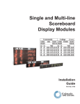
Installation Guide
Thermal Conductivity Detector on a 6850 GC
Accessory G2623A
2
© Agilent Technologies 2007
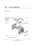
Safety Information
Safety Symbols
All Rights Reserved. Reproduction,
adaptation, or translation without
permission is prohibited, except as allowed
under the copyright laws.
The Agilent Technologies Thermal
Conductivity Detector meets the following
IEC (International Electrotechnical
Commission) classifications: Safety Class 1,
Transient Overvoltage Category II, and
Pollution Degree 2.
Warnings in the manual or on the
instrument must be observed during all
phases of operation, service, and repair of
this instrument. Failure to comply with these
precautions violates safety standards of
design and the intended use of the
instrument. Agilent Technologies assumes
no liability for the customer’s failure to
comply with these requirements.
Part number G2623-90108
Replaces G2623-90107
First Edition, JAN 2001
Second Edition, Feb 2007
Replaces Part No. G2623-90100 Operating
and Service Manual.
HP® is a registered trademark of
Hewlett-Packard Co.
Printed in USA
This unit has been designed and tested in
accordance with recognized safety
standards and designed for use indoors. If
the instrument is used in a manner not
specified by the manufacturer, the
protection provided by the instrument may
be impaired. Whenever the safety protection
of the Agilent G2623 has been
compromised, disconnect the unit from all
power sources and secure the unit against
unintended operation.
Refer servicing to qualified service
personnel. Substituting parts or performing
any unauthorized modification to the
instrument may result in a safety hazard.
Disconnect the AC power cord before
removing covers. The customer should not
attempt to replace the battery or fuses in
this instrument.
WARNING
A warning calls attention to a condition or
possible situation that could cause injury to
the user.
CAUTION
A caution calls attention to a condition or
possible situation that could damage or
destroy the product or the user’s work.
Sound Emission Certification for Federal
Republic of Germany
Sound pressure Lp < 68 dB(A)
During normal operation
At the operator position
According to ISO 7779 (Type Test)
Schallemission
Schalldruckpegel LP < 68 dB(A)
Am Arbeitsplatz
Normaler Betrieb
Nach DIN 45635 T. 19 (Typprüfung)
Agilent Technologies, Inc.
2850 Centerville Road
Wilmington, DE 19808-1610
USA
4
Installing a Thermal Conductivity Detector on a
6850 Gas Chromatograph
These instructions are divided into two parts:
•
Part 1 to prepare the Electronic Pressure Control ("EPC") module for
later installation into the Agilent 6850 Gas Chromatograph ("GC")
•
Part 2 to perform the actual Accessory installation into the GC
Part 1: Preparation of the TCD EPC module
Locate the following item found in your Accessory kit:
Covers Kit G2630-60080 consisting of:
Qty.
Front EPC cover
1
Back EPC cover
1
Hex nuts, 7/16-inch
3
Grommet, 7/16-inch
1
Screw, M4 x12 mm, pan head
3
Copyright© 2007
Agilent Technologies
Printed in USA Feb 2007
Agilent Part No. G2623-90108
5
Installing a Thermal Conductivity Detector on a 6850 Gas Chromatograph
Caution
6
Some of these assemblies contain printed circuit boards so standard ESD
precautions must be followed: use a static control wrist strap (supplied)
connected to a suitable ground in handling the assemblies.
Installing a Thermal Conductivity Detector on a 6850 Gas Chromatograph
The following tools are required for this assembly:
Tools Required
Torx™ T-20 driver
7/16-inch open end wrench or nut driver
Procedure
1.
Prepare a suitable clean, dry, static-free work area.
2.
Place the detector system assembly such that its EPC module is
centered in your work area with its tubes oriented away from you and
its ribbon cable extending to the right.
3.
Remove dust caps from the gas connection fittings.
4.
Install the back cover onto the three gas fittings making sure the label
passes through slot provided. Loosely secure the cover using 7/16-inch
hex nuts, one onto each fitting.
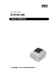
7
Installing a Thermal Conductivity Detector on a 6850 Gas Chromatograph
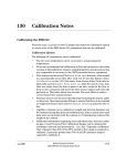
Location for TCD
switching valve cable
Install the TCD Swiching Valve cable
8
1.
Locate the TCD Switching Valve cable extending from the EPC module
and tie a knot in it as a strain relief approximately 30 - 35 mm (1.2 1.4 in) from the connector.
2.
Locate the supplied small black grommet, cut it vertically on one side,
and fit it around the cable wires such that the grommet is located
between the connector and your tied knot.
3.
Install the grommet and cable into the hole provided in the cover. A
small flat-blade screwdriver or similar tool may be useful in properly
seating the grommet into its hole.
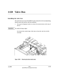
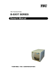
Installing a Thermal Conductivity Detector on a 6850 Gas Chromatograph
Connector
Grommet
Strain relief
knot
Prepare the EPC module cable
1.
Reorient the module such that the ribbon cable is upwards and gas
fittings are to the left.
2.
Fold the cable first to the left and gently crease it at the PC board to
maintain the direction. Then fold the cable back on itself to the right
and make a gentle crease such that the second fold is just inside the justinstalled back cover.
9
Installing a Thermal Conductivity Detector on a 6850 Gas Chromatograph
3.
10
Next, fold and gently crease the cable back on itself again, but at an
angle such that it now extends at 90-degrees away from you (in the
direction of tubing from the module).
Installing a Thermal Conductivity Detector on a 6850 Gas Chromatograph
If correctly done, the cable and its folds will be entirely within the body
of the module, and the free end of the cable and its connector will
extend from the module in the direction of the tubing.
4.
Fit the front cover onto the previously-installed back cover, securing it
loosely using three screws provided, two in the gas fittings side and one
in the PC board side. Make sure the ribbon cable and its connector exit
through the slot provided.
11
Installing a Thermal Conductivity Detector on a 6850 Gas Chromatograph
5.
12
Finally, firmly secure all cover screws and hex nuts on the gas
connection fittings. Then replace protective dust caps onto the gas
connection fittings to maintain cleanliness.
Installing a Thermal Conductivity Detector on a 6850 Gas Chromatograph
Add the TCD Switching Valve extender cable
1.
Locate the TCD Switching Valve extender cable and two large grommets.
2.
Connect the extender cable to the TCD Switching Valve cable from the
assembled EPC module making sure connectors lock together.
3.
Loop the free end of the combined cable through the grommets to hold
them in place.
This completes EPC module preparation for this Accessory.
13
Installing a Thermal Conductivity Detector on a 6850 Gas Chromatograph
Part 2: Installation of the TCD Accessory
This kit contains:
Kit G2623-64000
Qty.
Thermal conductivity detector system
1
Performance evaluation sample kit
1
Bottom insulation
1
Seal insulation
1
Plastic grommet
1
Screw, M4 x 12 mm, pan head
5
Wrist strap, disposable, large
1
Installation sheet (this document)
1
The TCD assembly is a factory-assembled, tested, and calibrated unit.
Disassembly of the unit is not required for installation.
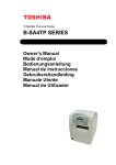
14
Installing a Thermal Conductivity Detector on a 6850 Gas Chromatograph
Heater/sensor cable
PRT and
filament wires
TCD assembly
Switching valve extension
cable and grommet
Flow manifold cable
Bottom insulation
Screws
Plastic
grommet
Signal
board
Seal insulation
Tubing plugs
Tools Required
Torx™ T-20 driver
Flat blade screwdriver
Open end wrenches
Safety Information
Before continuing, read the safety information on your Agilent 6850 Gas
Chromatograph User Information CD-ROM.
15
Installing a Thermal Conductivity Detector on a 6850 Gas Chromatograph
Prepare for Installation
WARNING
Before proceeding, turn off the oven and any heated zones and let them cool
down. Turn off all detector gases at their supplies, then turn off the main
power switch and unplug the power cord.
1.
Open the lid. If a column is installed, disconnect it at the detector end.
Remove the nut warmer, insulation, and capillary adapter, if present.
Close the lid.
2.
Turn all gases off at their sources. Disconnect the carrier and detector
gas tubing from the back panel of the instrument.
Disconnect gas supply tubing
from these fittings
BNC
BNC
To Base - T
To Base - T
Local Talk
Local Talk
16
Installing a Thermal Conductivity Detector on a 6850 Gas Chromatograph
Remove the Lid Top Cover
Remove vent lines,
if present
Lid top cover, without
valve box accessory
Remove T-20 Torx™
screws (8 places)
Remove detector
cover, if desired
Remove the lid top cover.
Disconnect the Heater/Sensor Cable
1.
Trace the detector heater/sensor cable to the wiring harness near the
injection port cooling fan.
2.
Disconnect the cable.
Raise the Lid to the Service Position
1.
Open the lid. Locate the counterbalance cam in the left rear corner
under the lid. Loosen the screw on the right side of the cam. This allows
the stop plate to drop down.
17
Installing a Thermal Conductivity Detector on a 6850 Gas Chromatograph
Cam follower
Stop plate
Screw
Counterbalance cam
WARNING
18
2.
Raise the lid until it is stopped by the safety cable.
3.
Raise the stop plate and tighten the screw to lock the lid in the upright
service position.
The lid is heavy. Always lock the lid when it is in the service position.
Installing a Thermal Conductivity Detector on a 6850 Gas Chromatograph
Remove the Detector Electronics Cover
1.
Loosen the two bottom screws on the detector electronics cover.
Remove screw
Detector electronics cover
Loosen screws
2.
Remove the top screw on the cover.
3.
Lift and remove the detector electronics cover.
19
Installing a Thermal Conductivity Detector on a 6850 Gas Chromatograph
4.
Loosen the signal board clamp.
Ribbon cable
Signal board
(FID shown)
Signal board clamp
A/D converter board
5.
Unplug the signal board from the A/D converter board.
6.
Disconnect the wiring from the signal board.
FID – Disconnect the ribbon cable. Unplug the ignitor cable. Pass both
cables through the hole to the top side of the lid.
The ribbon cable connector will not pass through the rubber grommet in
the hole. Use a small screwdriver to push the grommet to the top of the
lid; the cables will now fit through the hole.
20
Installing a Thermal Conductivity Detector on a 6850 Gas Chromatograph
Ribbon cable connector
Ignitor cable connector
TCD – Unplug the two-wire switching valve cable at the connector. To
release the PRT and filament wires, press on the orange tabs. Pass the
disconnected cables/wires through the hole to the top side of the lid.
Switching valve
cable connector
PRT wires
Filament wires
7.
Lower the stop plate on the lid cam. Pull the lid forward until the cam
follower rests on the curved surface of the cam. Leave the stop plate in
the "down" position.
8.
Close the lid.
21
Installing a Thermal Conductivity Detector on a 6850 Gas Chromatograph
Remove the Existing Detector and Flow Manifold
1.
On the top of the lid, loosen the connector cover plate and remove the
plates.
Cover plate screws
Gas manifold
(FID shown)
Manifold mounting
screws
Gas fittings
22
2.
Disconnect the gas fittings. The figure above shows the FID manifold;
the TCD manifold is similar but has only one gas connection.
3.
Trace the ribbon cable from the flow manifold and disconnect it from
the harness.
4.
Remove the three manifold mounting screws.
5.
Remove the screws holding the detector assembly in place.
Installing a Thermal Conductivity Detector on a 6850 Gas Chromatograph
FID – Remove four mounting screws.
FID mounting screws
(one concealed)
TCD – Remove two mounting screws.
Mounting screws
6.
WARNING
Lift the detector and flow manifold out of the lid as a unit.
The fibrous insulation material used in the Agilent 6850 can cause irritation
to the skin, eyes, and mucous membranes. Always wear gloves when
working with the insulation. If the insulation is flaky/crumbly, wear
protective eyewear and a respirator.
7.
Remove any insulation that may be in the hole under the detector.
Install the Thermal Conductivity Detector and Flow Manifold
1.
Place the bottom insulation in the detector hole. Align the flat sides
parallel to the sides of the lid.
2.
Slide the seal insulation onto the bottom of the detector. Align it to
cover the detector bottom.
23
Installing a Thermal Conductivity Detector on a 6850 Gas Chromatograph
3.
Align the thermal conductivity detector as shown and lower it into
place. Position the flow manifold. Check that no wiring or tubing is
trapped under either assembly.
Heater/sensor
cable connection
Switching valve
cable connection
Screws
PRT and filament
leads
4.
Secure the detector assembly to the lid with two screws.
5.
Secure the manifold to the lid with three screws.
Manifold cable connector
is under this plate
Connect gas line M here
24
6.
Plug the manifold ribbon cable into its connector under the connector
cover plate.
7.
Install the two connector cover plates.
8.
Connect the gas supply line labeled M to the center fitting on the flow
manifold.
Installing a Thermal Conductivity Detector on a 6850 Gas Chromatograph
WARNING
The gas line labelled H is plumbed to the hydrogen supply. Be sure to plug
this line to prevent accidental release of hydrogen gas into the instrument.
9.
The A and H gas lines are not used with the TC detector. If they are not
already plugged, plug them with the brass plugs and push them down
into the space under the manifold fittings. Avoid kinking the tubing.
Connect the Heater/Sensor Cable
Connect the detector heater/sensor cable to the wiring harness near the
injection port cooling fan.
Install the Switching Valve Extension Cable and Grommet
1.
Locate the oblong hole for the switching valve extension cable. If there
is a grommet in the hole, remove it.
2.
Pass the end of the extension cable through the oblong hole into the
signal board space. Use a small flat blade screwdriver to install the
grommet in the oblong hole.
Connect the other Leads and the Signal Board
1.
Raise the lid to the upright service position and lock it in place by
raising the stop plate and tightening the screw.
2.
Locate the round hole for the PRT and filament leads. If there is a
grommet in the hole, remove it and install the one from the kit. Pass the
two PRT leads and the two filament leads through the grommet into the
signal board space.
3.
Plug the signal board into the A/D converter board and secure it with
the signal board clamp.
4.
Connect the PRT and filament leads to the signal board by pressing the
orange tabs and inserting the appropriate wires. Polarity does not
matter, but the wires must go to the correct pair of connectors.
•
PRT leads have light-colored insulation
•
Filament leads have thick, black insulation
25
Installing a Thermal Conductivity Detector on a 6850 Gas Chromatograph
Switching valve
cable connector
PRT wires
Caution
Filament wires
Double check the PRT and filament connections before proceeding. An
incorrect connection can damage the detector when power is restored.
5.
Plug the switching valve extension cable into the signal board.
6.
Install the detector electronics cover and tighten all three screws.
7.
Lower the stop plate on the lid cam. Pull the lid forward until the cam
follower rests on the curved surface of the cam. Raise the stop plate
behind the cam follower and tighten the screw.
8.
Close the lid.
9.
Install the lid top cover.
Finishing Up
26
1.
If not already present, make an external T-connection between the
carrier gas supply and the Reference/Makeup gas fitting on the back of
the instrument.
2.
Install the capillary adapter, if used.
3.
Restore the column connection.
4.
Restore carrier gas to the instrument.
5.
Restore power.
6.
Apply your normal operating pressures. Leak-check the manifold, back
panel, and column fittings.
Printed on recycled paper.
This product is recyclable.
Agilent Technologies, Inc.
Printed in USA April 2007