1
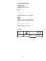
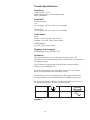
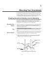
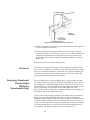
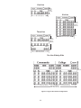
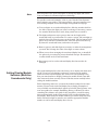
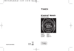
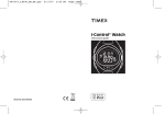
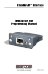
Single and Multi-line
Scoreboard
Display Modules
Installation
Guide
F218 Rev 0705
Colorado Time Systems
Corporate Office
1551 East 11th Street
Loveland, CO 80537 USA
Sales : 800-279-0111 or +1 970-667-1000
Service: 800-287-0653 x256 or +1 970-667-1000 x256
Service Fax: 970-667-1032
Web: www.coloradotime.com
Email: [email protected]
Part Number F218, Rev. 0705
©2005 Colorado Time Systems. All rights reserved.
Table of Contents
1 Introduction
Receiving Your Equipment . . . . . . . . . . . . . . . . . . . . . .1-1
Scoreboard Package Contents. . . . . . . . . . . . . . . . . . . . 1-1
Scope of this Instruction Guide . . . . . . . . . . . . . . . . . . .1-2
CE and UL Information . . . . . . . . . . . . . . . . . . . . . . . .1-3
2 Electrical and Data Cable Requirements
Electrical Wiring . . . . . . . . . . . . . . . . . . . . . . . . . . . . . .2-1
Data Cable Wiring . . . . . . . . . . . . . . . . . . . . . . . . . . . . .2-4
Permanent Data Cabling . . . . . . . . . . . . . . . . .2-4
Installing the Removable Cable . . . . . . . . . . . .2-4
Installing Signage . . . . . . . . . . . . . . . . . . . . . . . . . . . . .2-5
3 Mounting Your Scoreboard
Preparing Scoreboard Display Lines for Mounting . . .3-1
Mounting Sign Panels . . . . . . . . . . . . . . . . . . .3-1
Arranging Scoreboard Display Digits . . . . . . .3-2
Setting Display Module Switches . . . . . . . . . .3-4
Testing Scoreboard Display Lines . . . . . . . . . .3-6
Installing Brackets and Unistruts . . . . . . . . . . . . . . . .3-7
Measurements . . . . . . . . . . . . . . . . . . . . . . . . . .3-7
Installing Mounting Brackets . . . . . . . . . . . . .3-9
Mounting and Leveling Unistruts . . . . . . . . . .3-12
Mounting Scoreboard Display Lines . . . . . . . .3-14
Optional Unistrut Covers . . . . . . . . . . . . . . . .3-16
4 Connecting and Testing Your Scoreboard
Linking a Multi-line Scoreboard . . . . . . . . . . . . . . . . . .4-1
Attaching Data Cables . . . . . . . . . . . . . . . . . . . . . . . . . .4-1
Powering Up Your Scoreboard . . . . . . . . . . . . . . . . . . .4-2
Final Testing . . . . . . . . . . . . . . . . . . . . . . . . . . . . . . . . .4-2
5 Troubleshooting and Service
Troubleshooting . . . . . . . . . . . . . . . . . . . . . . . . . . . . . . .5-1
Service . . . . . . . . . . . . . . . . . . . . . . . . . . . . . . . . . . . . . .5-3
Removing a Digit . . . . . . . . . . . . . . . . . . . . . . .5-3
Segment Base Clip & Bearing Replacement . . 5-4
Removing/Replacing Digits . . . . . . . . . . . . . . .5-6
Removing/Replacing a Control Board . . . . . . .5-7
TOCi
TOCii
1
Introduction
Thank you for purchasing a Colorado Time Systems Scoreboard Display.
Whether you have chosen light-reflective digits or LED digits, your display
will enhance your program and provide exceptional visibility. Best of all,
you will never change another light bulb. Designed specifically for the
swimming pool environment, your scoreboard’s high-quality construction
resists corrosion in any environment, giving you years of trouble-free service.
The scoreboard is an integral part of your Colorado Time Systems’ sports
timer package. It displays results and other information for Swimming,
Diving, Water Polo, Synchronized Swimming, Track, and more. It can also
be used as a training pace clock in conjunction with your CTS sports timer
and Pace Clock software.
Before You Begin
Proper installation of your new scoreboard is very important. Please read
this installation guide carefully before installing your scoreboard to make
sure you have everything you need before beginning. When you are ready
to install your scoreboard, carefully follow the step-by-step instructions in
this manual. If you should experience any difficulties installing or using
your new scoreboard, check the Troubleshooting and Maintenance sections in this manual first. If you are still unable to correct the problem,
call Colorado Time Systems’ Customer Service Department (x256) toll-free
at 1-800-287-0653 in the US and Canada, or (970) 667-1000.
Before you begin to install your new scoreboard, check all parts received
against the packing list and your order to ensure that you received all necessary parts. If any parts are missing, call Colorado Time Systems’
Customer Service Department (x256) toll-free at 1-800-287-0653 in the
U.S. and Canada, or (970) 667-1000.
Scoreboard
Package Contents
Although each scoreboard package is custom assembled to match the customer’s order, many items are always included. The quantity of each item
you receive depends on your order. Some items are only included in multiline scoreboard packages.
Scoreboard display line(s)
Sign panel(s)
Signage transfer(s)
Sign panel mounting brackets and hardware
Removable data cable
Scoreboard link data cables (multi-line only)
Unistruts
Universal mounting brackets
“U” mounting brackets
Mounting bracket hardware
Installation guide
1-1
Scope of this Instruction Guide
This installation guide covers all aspects of a normal scoreboard installation. It is not intended to address every possible scoreboard configuration
or mounting scheme. It is intended to provide enough information so that
you can easily adapt the instructions to meet your specific requirements.
This installation guide also includes Troubleshooting and Maintenance
sections which cover the most common user correctable problems and
maintenance issues.
To find specific information quickly, refer to the Table of Contents at the
front of this installation guide. For answers to installation questions or
problems not covered here, call Colorado Time Systems’ Customer Service
Department (x256) at 1-800-287-0653 in the U.S. and Canada, or (970)
667-1000.
1-2
Product Specifications
Environmental
Temperature: 0°C - 50°C
Humidity: 90% (non-condensing)
Altitude: 0 to 3000 m
Electrical
Supply Voltages:
U.S.
AC Supply: 115 VAC ±10% @ 3.0A, 50-60Hz
International
AC Supply: 230 VAC ±10% @ 1.5A, 50-60Hz
Fuses:
4009:
Primary - 3A, 250V, Time Lag, 5mm x 20mm
Secondary - 5A, 250V, Time Lag, 5mm x 20mm
LED:
5A, 250V, Time Lag, 5mm x 20mm
Input and Output Connections
SCBD Port: Input - RS-232, ±12V
Symbols
Fuse
Protective
Conductor
Terminal
Alternating
Current
1-3
Installation/Maintenance
This product is intended to be used in an indoor or outdoor swimming pool
environment. When the scoreboard is operated in the U.S. it must be used
in accordance with the National Electric Code. When the scoreboard is
operated elsewhere it must be used in accordance with all appropriate
national and local electrical codes and regulations for the country of installation. The AC power cord should not be accessible during normal operations. Connect only to a circuit that is protected by a ground-fault circuit
interrupter (GFCI).
These scoreboards are equipped with a 3-wire grounding-type plug, a plug
having a third (grounding) pin. This plug will only fit into a groundingtype power outlet. This is a safety feature. If you are unable to insert the
plug into the outlet, contact a qualified electrician to replace your obsolete
outlet. Do not defeat the purpose of the grounding-type plug.
Using these scoreboards in a manner not specified by Colorado Time
Systems may cause the protection provided by the equipment to be
impaired.
Other than those maintenance items described in the user manual, there
are no user serviceable parts on these scoreboards. When servicing those
parts shown in the user manual, use only replacement parts specified.
When replacing fuses or any similar servicing of the unit, make sure the
unit is unplugged.
It is recommended that these scoreboards be installed by Colorado Time
Systems personnel. However, if you have chosen to install the board without a CTS technician and you experience difficulties, check the
Troubleshooting and Maintenance sections in this manual first. If you are
still unable to correct the problem, call Colorado Time Systems’ Customer
Service Department (x256) toll-free at 1-800-287-0653 in the U.S. and
Canada, or (970) 667-1000 for assistance or to schedule a technician for
your installation.
1-4
Produkt Spezifikationen
Umgebung
Temperatur: 0°C - 50°C
Luftfeuchtigkeit: 90% (nicht-kondensierend)
Höhe: 0 bis 3000 m
Elektrizität
Stromversorgung:
U.S.
AC Verorgung: 115 VAC ±10% @ 3.0A, 50-60Hz
International
AC Verorgung: 230 VAC ±10% @ 1.5A, 50-60Hz
Sicherungen:
4009:
Primär - 3A, 250V, Träge, 5mm x 20mm
Sekundär - 5A, 250V, Träge, 5mm x 20mm
10LED-8R/8RO:
2A, 250V, Träge, 5mm x 20mm
Eingänge und Ausgänge
SCBD Ausgang: Input - RS-232, ±12V
Installation
Dieses Produkt kann für innen und außen benutzt werden. Die
Installation der Anzeigetafel muß nach den Vorschriften der entsprechenden Länder erfolgen.
Das AC Stromversorgungskabel solite geschützt und während des
Betriebes nicht zugänglich sein.
Wenn die Anzeigetafein nicht so insalliert werden wie von CTS spezifiziert, kann die Funktion beerinträchtigt werden.
Es gibt keine weiteren notwendigen Service-Wartungsarbeiten für die
Anzeigetafel-Serien als die in dem Handbuch anfgeführten positionen.
Die Anzeigetafel-Serien sollten nur van autorisiertem Personal oder von
der Firma Colorado Time Systems installiert werden.
Sicherung
Schutzleiter
Wechselspannung
Symbole
1-5
1-6
2
Electrical and Data Cable Requirements
This chapter contains instructions for electrical and data cable wiring
which must be completed before you install your scoreboard. Follow these
instructions carefully.
Electrical Wiring
Note
All electrical wiring must be carried out in accordance with the applicable
national, state and local electrical codes. All electrical wiring should
be done by a qualified electrician.
This section contains the Colorado Time Systems’ recommended methods
of providing power to your new scoreboard. Follow these recommendations
during your installation.
Branch Circuit Connection
method (4009-style only)
The 4009 (light-reflective) product has been designed to allow it to be
installed using a fixed wiring method. Fixed wiring can be accomplished by
connecting standard electrical conduit to the knock-out provided in the
metal plate at the power supply end of the display. Remove the strain
relief from the existing power cord and pull one foot of cord inside the
power end cover. Cut and discard the remaining length of power cord.
Remove about 6 inches of the outer cable jacket and strip all three wires:
black, white and green (or blue, brown and green/yellow in Europe) as
appropriate for wire nut termination. Wire-nut the branch circuit hot wire
to the black wire of the 4009 power cord. Wire-nut the branch circuit neutral wire to the white wire of the 4009 power cord. Wire-nut the branch
circuit ground wire to the green wire (or green/yellow wire in Europe) of
the 4009 power cord.
NOTE: Electrical conduit and wire nuts are not provided by Colorado
Time Systems. Use copper conductors only. For supply connections, use
wires suitable for at least 75°C
WARNING: This procedure must only be done by a qualified electrician
or CTS personnel and must be done in accordance with the National
Electric Code (NEC) or the applicable local and national electrical codes.
Duplex Electrical Outlet
Connections method
(for 4009 or LED)
1) For every two scoreboard lines, provide a duplex electrical outlet located
as indicated in the six-line example in Figure 2-A. Following this recommended arrangement makes for a clean wiring layout and offers a convenient source of power at each module for test and service equipment.
2-1
5 3/4"
14.6 cm
Data Connection
Box
19"
(48.3 cm)
115 VAC @ 15A
Duplex Outlet
28"
(71.1 cm)
94"
238.8 cm
28"
(71.1 cm)
102" (259.1 cm)
Scoreboard
On/Off Switch
Location of duplex outlets for 4009
LANE PLACE
TIME
12"
112"
28"
28"
14"
97.625"
Location of duplex outlets for LED
Figure 2-A
2) Mount the duplex electrical outlets as shown in Figure 2-B. If your pool
is under construction or renovation, flush mounting with wiring inside
the walls is the recommended method. Otherwise, surface mounting of
conduit and outlets is acceptable. Note the orientation of the outlet
boxes if surface mounted as shown in Figure 2-B.
Note
As with any computer equipment, your scoreboard requires dedicated electrical service lines. If you are unsure how to provide dedicated electrical
lines to your scoreboard, consult a qualified electrician.
2-2
Orientation of duplex outlets and data connection box
Figure 2-B
3) Mount the scoreboard On/Off switch near the scoreboard, six to seven
feet above the floor, or in the timing booth. Scoreboard switches located
in the pump room or other inconspicuous locations can lead to premature scoreboard failure because the scoreboards are left on continuously. Mounting the On/Off switch near the scoreboard or in the timing
booth is also helpful for service personnel who must be able to turn the
scoreboard on and off as needed.
4) When all electrical wiring is completed, proceed to the next step.
2-3
Data Cable Wiring
There are two ways to accomplish data transmission to the scoreboard.
You can use the removable two-wire data cable provided with your scoreboard, or you can install the data cable permanently in conduit using oneinch conduit from the scoreboard location to a 12" x 12" x 6" box at the
nearest timing location. Select the data cabling method you would like to
use and follow the appropriate instructions to install it.
Permanent Data
Cabling
1) Place one Data Connection Box in the timing booth. The exact location
of this connection is not critical and should be determined by the
configuration of your timing booth. Choose a convenient location near
the timing table. The main consideration is to make it easy for you to
run the cable from your Colorado Time Systems’ Sports Timer to the
Data Connection Box. Install the Data Connection Box in the selected
location.
2) Route conduit to the place where you will be installing your scoreboard.
If your pool is under construction or renovation, install the conduit
inside the walls.
3) Mount the scoreboard Data Connection Box at either the top or bottom
of your scoreboard location. Figure 2-A shows the Data Connection Box
mounted at the top, in line with the duplex electrical outlets. As with
the electrical outlets, the Data Connection Box may be mounted flush
or on the surface of the wall.
Installing the
Removable Data
Cable
You do not need to install the removable data cable before installing your
scoreboard. In some instances, it may be more convenient to do so, in others, the data cable may just be in the way when you are installing your
scoreboard. Your situation will determine whether to install now or later.
1) Route the removable data cable supplied with your scoreboard from the
timing booth to the scoreboard. Be sure the cable is not in a location
where it can be tripped over. Secure the cable with tape if necessary.
This is especially important if you intend to leave the removable data
cable in place for an extended period of time.
2) Route the data cable either to the top or bottom of your scoreboard location. It can be attached to the scoreboard at either location.
2-4
Installing Signage
Before you mount your scoreboard, it is recommended that you put the
signage on the sign panels.
This procedure requires a felt-tip marker and masking tape. A rubber
roller is also helpful but is not necessary.
1) Locate all sign panels and signage included in your scoreboard package.
2) Your signage is delivered sandwiched between a carrier paper on the
bottom and a transfer paper on the top. Use a felt-tip marker to draw a
line on the transfer paper at the bottom of the words on the signage.
3) Place the signage in its relative position on the sign panel.
For the 4009-style scoreboards, the sign panel sits in a groove in the top
front edge of the scoreboard display line. For LED scoreboards, the sign
panel slides into two grooves (top and bottom) on a separate scoreboard
module.
Measure the depth of the groove(s). Make sure the signage is positioned
so that no part of any word will be obscured by the mounting groove or
the frame of the scoreboard display line.
4) Align the signage evenly across its length at the desired height above
the appropriate scoreboard digits. Tape the entire right edge of the signage to the scoreboard panel with masking tape.
5) Beginning at the left edge and working toward the right, lift the transfer paper and signage away from the bottom carrier paper. When you
reach the right edge of the signage, remove the carrier paper entirely,
being careful not to lift the tape at the right edge of the signage.
6) Beginning at the right edge and working toward the left, re-apply the
signage and transfer paper evenly to the sign panel using a rubber roller
or the heel of your hand.
7) After applying the signage, go over it again with the roller or your hand
with more pressure to secure it in place.
8) When you are satisfied that the signage has adhered to the sign panel in
the desired position, slowly and carefully remove the transfer paper
from the signage.
9) Handle the sign panels carefully for a couple of days until the adhesive
sets fully, after which the signage is secure.
10) Set the sign panel you just completed in a location away from the
work area where it will not be disturbed. You will need it later.
11) Repeat the process for each remaining piece of signage.
2-5
2-6
3
Mounting Your Scoreboard
This chapter contains instructions for mounting your scoreboard in a variety of configurations. Since each scoreboard installation is customized to
fit your needs, only representative installations can be shown here. If after
carefully reading these instructions you are unsure how to install your
scoreboard, call Colorado Time Systems’ Customer Service (x256) toll-free
at 1-800-287-0653 in the U.S. and Canada, or (970) 667-1000.
Preparing Scoreboard Display Lines for Mounting
This section contains all instructions for preparing your scoreboard display line(s) for mounting. Make all preliminary preparations on the
ground before installing your scoreboard display lines. Once installed, it is
more difficult to make changes to scoreboard display lines.
Mounting Sign
Panels
This section explains how to mount sign panels on your scoreboard display
lines. It is usually more convenient to mount the sign panels before
installing your scoreboard display lines. The process differs between 4009style boards and LED boards.
Note
You should install your signage on each sign panel before installing the
sign panels on the scoreboard display lines. See page 2-4 above for instructions.
4009-style boards
1) Locate the sign panel mounting brackets included in your scoreboard
package. Each sign panel requires two mounting brackets.
2) Place a sign panel mounting bracket in the top groove at the outside
edge of the scoreboard display line on which the sign panel is to be
mounted as shown in Figures 3-A and 3-B.
Twist Mounting Bracket
into Place
Sign Panel
Mounting Bracket
Top of
Scoreboard
Frame
Sign Panel
Mounting Bracket
Front of Scoreboard
Display Line
Figure 3-A Mount sign panel mounting bracket
3-1
Figure 3-B Twist mounting bracket into place
3) Twist the mounting bracket one-quarter turn until it locks into place as
shown in Figures 3-A and 3-B.
4) Locate the appropriate sign panel. Slide the bottom edge of the sign
panel into the groove at the front top edge of the scoreboard display line
and attach the aluminum strip along the top of the sign panel to the
mounting brackets with the supplied mounting hardware as shown in
Figure 3-B.
5) Repeat the process to install all sign panels.
LED boards
Locate the extra sign panel module(s) and set aside for installation with
the rest of your modules. Continue on to the following sections for configuring your scoreboard module(s), and install your sign panel module(s) at
the same time and in the same manner as the rest of your modules. The
sign panels themselves slide in to the modules.
Arranging Scoreboard
Display Digits
(Multi-line
Scoreboards Only)
Before installing your scoreboard display lines, you may need to arrange
the digits to match your signage. All scoreboard display lines leave the factory arranged in a standard configuration as shown in the one-line scoreboard in Figure 3-C. Scoreboard lines with eight digits are arranged to display one lane digit, one place digit, and six time digits with colon.
Scoreboard lines with 10 digits are arranged to display two lane digits, two
place digits, and six time digits with colon.
If you need to slide the digits’ position(s), determine where you want the
digits on each scoreboard display line before you begin moving them.
Examples of some typical scoreboards appear in Figure 3-C. While it’s fine
to slide the digits along the track, do not change the order of the digits -- if
you do, the scoreboard will not operate properly. Do not remove any digits,
as leaving unused digits in the scoreboard frame keeps digit spacing correct and keeps the digits available for later or emergency use.
3-2
One Line
4009:38"
(96.5 cm)
LED: 42"
(106.7 cm)
Six Line
4009: 102" (259.1cm)
LED: 97.625" (248 cm)
4009:108"
(274.3 cm)
LED:112"
(284.5 cm)
Three Line
4009: 102" (259.1cm)
LED: 97.625" (248 cm)
4009: 86"
(218.4 cm)
1
2
3
4
5
HOME
LED: 98"
(248.9 cm)
6
GUEST
4009: 102" (259.1cm)
LED: 97.625" (248 cm)
Ten Line Side-by-Side
108"
(274.3 cm
4009: 102" (259.1cm)
LED: 97.625" (248 cm)
4009: 204" (518.2 cm)
LED: 195.25" (495.9 cm)
4009: 102" (259.1cm)
LED: 97.625" (248 cm)
Figure 3-C Typical Scoreboard Configurations
3-3
Note
Shut off power to the score board prior to moving any digits and wait at
least one minute for all internal power to discharge.
For specific scoreboard examples, refer to your Colorado Time Systems’
timer software user guide(s). The user guide for each sport contains a section showing examples of scoreboard digit arrangement and signage.
1) To move digits on a scoreboard display line, slide the weather shield to
the left to expose the digits you want to rearrange. If necessary, remove
the weather shield and set it aside, being careful not to scratch it.
2) The digits and spacers rest in grooves that run the length of the
scoreboard frame, top and bottom. To remove a spacer, lift it straight up
until the lower lip clears the groove at the bottom. Tilt the bottom of the
spacer away from the scoreboard frame, lower the spacer until the top
lip clears the scoreboard frame, and remove the spacer.
3) Remove spacers, and slide digits as necessary to make the arrangement
you need. Don’t change the order of the digits or remove them.
4) When you are done arranging the scoreboard display line, re-install all
the spacers by reversing the process described in step 2. Re-install the
weather shield on the scoreboard frame.
5) Repeat steps 1-4 for each scoreboard display line that needs to be
arranged.
Setting Display Module
Switches (Multi-line
Scoreboards Only)
All scoreboard display lines leave the factory set to display data from module 0F. If you have a multi-line scoreboard, you must set the module
switch in each scoreboard display line to the code corresponding to the
data you want that line to display. Setting the module switch is not difficult, but must be done correctly. Please read this section carefully before
setting the module switches.
Before beginning, make sure you know the module number for the information you want each scoreboard display line to display. Examples of
every available scoreboard module appear in Colorado Time Systems’ software user guides, for example, Swimming, Diving, or Water Polo. After
consulting the software user guide for the program(s) you will be using
this scoreboard with, decide which module each scoreboard display line
will display. Write down the module numbers you will be using. You may
find it extremely helpful to attach a note with the appropriate module
number to each scoreboard display line to be set.
3-4
Now that you know what modules you want to display, follow these steps
to set the scoreboard display lines to match:
1) Slide the weather shield to the left to expose the digits on the right
end of the scoreboard display line. The control board, which contains
the module switch, is behind two of the scoreboard’s digits:
- 4009 and older 8-digit LED: digits 7 and 8 (the rightmost digits)
- newer 8-digit LED and 10-digit LED: digits 4 and 5
(the center digits)
2) Remove these two digits from the scoreboard frame as follows: The
digits rest in a groove that runs the length of the scoreboard frame, top
and bottom. To remove a digit, lift the digit straight up until the lower
lip of the PCB clears the groove at the bottom of the scoreboard frame.
Tilt the bottom of the digit away from the scoreboard frame, lower the
digit until the top lip clears the scoreboard frame, and remove the digit.
Note
Do not allow digits to hang from their wiring! The best way to support a
temporarily removed digit is to turn the digit around and rest its lower lip
in the weather shield groove on the scoreboard frame.
4009
LED
Figure 3-D Scoreboard Control Boards
3-5
3) The control board, as shown in Figure 3-D, is now visible. Note the location of the module switch. Refer to the chart inside the scoreboard
frame module switch settings. Charts for module switch settings for the
various revisions of scoreboards are also available on our website,
www.coloradotime.com, in the customer service section.
4) Using a pen or small screwdriver, carefully set the switches to the
proper position for your needs.
5) Check your work against the chart in the scoreboard frame or from the
Colorado Time Systems website.
6) When you have set the module switch correctly, replace the digits in
their proper order and slide the weather shield back over the scoreboard
display line.
7) Repeat steps 1-6 for all remaining scoreboard display lines.
Testing Scoreboard
Display Lines
This section describes how to test your configured scoreboard display lines
before installing them. If there are any configuration or other problems, it
is much easier to correct them while the scoreboard display lines are on
the ground.
If an electrical outlet is nearby, plug one scoreboard display line into it.
You may also run an extension cord to the scoreboard display lines if an
outlet is not handy.
Note
Make sure the extension cord you use is a heavy-gauge, three wire type
with three-prong plugs on both ends. Also, be very careful to keep the
extension cord away from the pool or water puddles on the pool deck.
1) When you plug in a scoreboard display module, it goes through
an internal power on sequence. On 4009 boards, all digits turn to their
blank position for 7 seconds. On LED boards, all the digits light up
briefly.
2) The module code you set above is then displayed. Newer models will
also display the firmware revision; older models may display the data
speed. If the scoreboard does not display anything, turn to the
Troubleshooting section on page 5-1 for remedies.
3) Ensure that the code displayed is the code you want that scoreboard
line to display. If not, reset the code as explained on page 3-5 above.
Example swimming module displays are shown in Figure 3-E.
Note
On 8-digit boards, there is only one digit for lane; therefore, lane 10 displays as A, lane 11 displays as b, and lane 12 displays as C, as shown in
Figure 3-E.
3-6
4) When done testing the scoreboard display line, unplug it.
5) Repeat steps 1-4 for the remaining scoreboard display lines.
Figure 3-E Scoreboard Codes for Swimming
Installing Brackets and Unistruts
This section contains instructions for installing the mounting brackets to
the wall of your building and mounting the unistruts which hold your
scoreboard to the mounting brackets. Follow these instructions carefully!
Measurements
Note
The first step in installing the mounting brackets and unistruts is to determine where to install them. Measure carefully and check your work before
installing the mounting brackets.
Before you can begin taking measurements, you must know exactly the
configuration of your scoreboard, including the number and placement of
all scoreboard display lines and sign panels.
3-7
Dimensions
4009 Scoreboard Display Lines:
Height: 14 inches (35.6 cm); Length: 102 inches (259.1 cm)
4009 Sign Panels:
Height: 10 inches (25.4 cm) OR 14 inches (35.6 cm) -- measure each of
your sign panels;
Length: 102 inches (259.1 cm)
LED Scoreboard display lines and sign panels:
Height: 14 inches (35.6 cm) Length: 97.625 inches (248 cm)
Marking Scoreboard
Locations
1) Add up the total height of all scoreboard display lines and sign panels
other than the top sign panel in each display column.
2) Select the vertical placement of the scoreboard on the wall. Be aware
that the lower scoreboards are mounted the easier they are to service.
Choose a vertical location no higher than necessary to provide good visibility and discourage vandalism.
Note
The bottom of the scoreboard should be a minimum of eight feet above the
floor to discourage vandalism.
3) Mark the wall where the top right and top left corners of the highest
scoreboard display line will be located. For 4009 installation, do
not adjust for the top sign panel as it is mounted on the top
scoreboard display line. If installing a two-column (side-by-side)
scoreboard, also mark the top of the center line between the two
scoreboard columns.
4) Mark the bottom right and bottom left corners of the lowest scoreboard
display line.
Note
Check Your Work
For corner-mounted scoreboards (one column only), all marks should be
71 inches (180.3 cm) out from the corner for 4009 and 67.875 inches (172.4
cm) out from the corner for LED. See Figure 3-H for an example.
For one-column scoreboards, you should now have four marks on the wall
indicating the corners of the entire scoreboard. For two-column (side-byside) scoreboards, you should have six marks on the wall, four indicating
the corners of the entire scoreboard, and two marking the center line of
the scoreboard.
Measure the distance between each set of top marks and bottom marks.
Then measure the unistrut supplied with your scoreboard. The two measurements should be the same. If there is a major difference between the
two dimensions, make sure you have accounted for all signage mounted
between scoreboard display lines. If you still cannot reconcile the two measurements, call CTS’s Customer Service (x256) toll-free at 1-800-287-0653
in the U.S. and Canada, or (970) 667-1000, before proceeding.
3-8
Installing Mounting
Brackets
Note
Multi-line Flat
Wall Mount
This section contains instructions for installing the mounting brackets on
the wall. Each type of scoreboard and mounting bracket has a separate
sub-section. Locate the type of scoreboard you are installing and follow the
instructions for it. If you are unsure about your scoreboard type or which
mounting brackets to use, call Colorado Time Systems’ Customer Service
(x256) toll-free at 1-800-287-0653 in the U.S. and Canada, or (970) 6671000 before proceeding.
Do not overtighten concrete inserts. Torque only to 10 in/lbs
These instructions apply to both one- and two-column scoreboard installations using “U” or universal brackets.
One-column Scoreboard Unistrut Spacing
4009: 102" (259.1cm)
LED: 97.625" (248 cm)
Two-column
Scoreboard
Unistrut Spacing
4009: 102" (259.1cm)
LED: 97.625" (248 cm)
4009: 102" (259.1cm)
LED: 97.625" (248 cm)
Figure 3-F Unistrut Spacing
1) From the top marks, measure down 6 to 8 inches (15.2 to 20.3 cm) and
make an “X” to indicate the location of the top brackets.
2) From the bottom marks, measure up 6 to 8 inches (15.2 to 20.3 cm) and
make an “X”to indicate the location of the bottom brackets.
3-9
3) The maximum vertical spacing between brackets is 66 inches (167 cm),
or four scoreboard display lines and one sign panel. Add additional
brackets between the top and bottom brackets at intervals of 66 inches
(167 cm) or less.
4) Carefully mark the locations of the holes in the selected mounting
brackets. Check the locations of all mounting brackets and drill-holes.
Refer to Figures 3-I and 3-J to check horizontal spacing between
brackets.
5) When you are sure all marks are accurate, drill mounting holes 2.5
inches (6.4 cm) deep, install mounting hardware in holes, and mount
brackets on hardware as shown in Figure 3-G. Make sure all hardware
is secured to 10 in/lbs torque. Do not overtighten concrete inserts.
Mounting Hardware for
Wall Brackets
TIghten nuts to 10"/lbs.
Torque Maximum
Drill 2.5" deep for
mounting hardware.
TIghten nuts to 10"/lbs.
Torque Maximum
Figure 3-G Install Mounting bracket hardware
Multi-line Corner
Mount using
Universal Brackets
Only one-column multi-line scoreboards can be installed in a corner. Twocolumn scoreboards must be installed on a flat wall using unistruts as
described above, or you must provide your own special frame for corner
mounting.
1) From the top marks, measure down 6 to 8 inches (15.2 to 20.3 cm) and
make an “X” to indicate the location of the top brackets.
2) From the bottom marks, measure up 6 to 8 inches (15.2 to 20.3 cm) and
make an “X” to indicate the location of the bottom brackets.
3) The maximum vertical spacing between brackets is 66 inches (167 cm),
or four scoreboard display lines and one sign panel. Add additional
brackets between the top and bottom brackets at intervals of 66 inches
(167 cm) or less.
4) Carefully mark the locations of the holes in the selected mounting
brackets. Check the locations of all mounting brackets and drill-holes.
Refer to Figure 3-H to check horizontal spacing between brackets.
3-10
5) When you are sure all marks are accurate, drill mounting holes 2.5
inches (6.4 cm) deep, install mounting hardware in holes, and mount
brackets on hardware as shown in Figure 3-G. Make sure all hardware
is secured to 10 in/lbs torque. Do not overtighten concrete inserts.
4009: 71" (180.3 cm)
LED: 68" (172.7 cm)
4009: 71" (180.3 cm)
LED: 68" (172.7 cm)
4009: 102" (259.1 cm)
LED: 97.625" (248 cm)
Figure 3-H: Corner Mounting
Single-line Flat
Wall Mount or
Corner Mount
1) From the top marks, measure down 7 inches (17.8 cm) and make an
“X” to indicate the center of the brackets.
4009: 92" (233.7 cm)
LED: 87.625" (222.6 cm)
4009: 102" (259.1cm)
LED: 97.625" (248 cm)
Figure 3-I: Flat wall mount using universal brackets
2) Carefully mark the locations of the holes in the selected mounting
brackets. Check the locations of all mounting brackets and drill-holes.
Note that the mounting holes for Universal brackets on a flat wall
mount are 92 inches (233.7 cm) apart for 4009 boards and 87.625
inches (222.6 cm) apart for LED boards. Refer to Figure 3-H to check
corner-mount horizontal spacing between brackets. Refer to Figure 3-I
to check flat wall mount horizontal spacing between brackets.
3) When you are sure all marks are accurate, drill mounting holes 2.5
inches (6.4 cm) deep, install mounting hardware in holes, and mount
brackets on hardware as shown in Figure 3-G. Make sure all hardware
is secured to 10 in/lbs torque. Do not overtighten concrete inserts.
3-11
Single-line Flat
Wall Mount using
“U” Brackets
1) From the top marks, measure down 3 inches (7.6 cm) and make an “X”
to indicate the center of the top brackets.
2) From the bottom marks, measure up 3 inches (7.6 cm) and make an “X”
to indicate the center of the bottom brackets.
3) Carefully mark the locations of the holes in the selected mounting
brackets. Check the locations of all mounting brackets and drill-holes.
Refer to Figure 3-J to check horizontal spacing between brackets.
4009: 102" (259.1cm)
LED: 97.625" (248 cm)
Figure 3-J Flat wall mount using U brackets
4) When you are sure all marks are accurate, drill mounting holes 2.5
inches (6.4 cm) deep, install mounting hardware in holes, and mount
brackets on hardware as shown in Figure 3-G. Make sure all hardware
secured to 10 in/lbs torque. Do not overtighten concrete inserts.
Mounting and Leveling
Unistruts
Mounting Unistruts
This section explains how to mount and level the unistruts on which your
scoreboard display lines will be installed. The unistrut mounting procedure is the same for both types of brackets.
1) Align the unistruts with the top and bottom marks you made for your
scoreboard.
2) Using the supplied bolts, washers, and nuts, attach each unistrut as
shown in Figure 3-K to the top and bottom mounting brackets only.
Tighten the bolts.
Note
Leveling Unistruts
If your installation uses more than two mounting brackets, install the
mounting hardware as shown in Figure 3-K but do not tighten the bolts
until you have leveled the unistruts.
Before fully tightening all unistrut mounting hardware, you must level the
unistruts.
1) Tighten the top and bottom unistrut bolts if you have not already done
so. Leave additional unistrut bolts loose.
2) Mount the bottom scoreboard display line, sliding the scoreboard display line’s mounting brackets into the unistrut as shown in Figure 3-L.
3-12
Universal Bracket
Brackets are
attached to wall
"U" Bracket
Wall
Scoreboard
Scoreboard
Mounts to Front
of Unistrut
Unistrut
Unistrut
Figure 3-K: Attaching unistrut to bracket, Top View
3) Place a level on top of the scoreboard display line. If it is not level,
either remove the scoreboard display line from the unistrut or support it
in place before attempting to adjust the unistruts.
4) To level the scoreboard display line, loosen the unistrut mounting bolts
and move the unistrut up or down as necessary.
5) When the bottom scoreboard display line is level, tighten all unistrut
mounting hardware securely. All remaining scoreboard display lines
will now be level when installed.
Figure 3-L: Mount scoreboard display line on unistruts
6) If you are installing a two-column (side-by-side) scoreboard, complete
steps 1- 5 for the left column. Repeat the procedure for the right column, but do not loosen the center unistrut as that will change the left
column as well. See Figure 3-N for an example of side-by-side mounting.
7) Leave the bottom scoreboard display line mounted. Follow the instructions in the next section to mount the remaining scoreboard display
lines.
3-13
Mounting Scoreboard
Display Lines
This section describes how to mount your configured scoreboard display
lines in one- and two-column (side-by-side) styles. Before installing your
scoreboard display lines, make sure you know the exact order in which
they are to be installed. Arrange them on the floor in order, from bottom
to top, to make sure you install each line in its proper place the first time.
One-column Flat Wall or
Corner Mount
1) Begin with the bottom scoreboard display line. Lift the scoreboard display line to the unistruts. Line up the bottom of the scoreboard display
line with the bottom of the unistruts.
2) Insert the scoreboard display line’s bracket tabs into the slots on the
unistrut as shown in Figure 3-L.
3) Carefully allow the scoreboard display line to settle into place.
Note
Do not let go of the scoreboard display line until you are sure it is securely
held in place by the unistrut.
4) Take one of the short data cables included with your scoreboard package. Attach one connector to the open data input connector on the justinstalled scoreboard display line. Attach the other end of the data cable
to the next higher scoreboard display line after installing it. When you
are finished with the entire installation, all scoreboard display lines
should be linked as shown in Figure 3-M.
Top Scoreboard Display
Line
To Data Connection Box
Next Scoreboard Display
Line
Next Scoreboard Display
Line
To Next Scoreboard
Display
Figure 3-M: Link multi-line scoreboard
5) Plug the power cable from the just-installed scoreboard line into the
nearest power outlet.
6) Repeat steps 1-5 for all remaining scoreboard modules.
3-14
Two-column (Side-by-side)
Flat Wall Mount
1) Begin with the bottom scoreboard display module on one side. Lift the
scoreboard display line to the unistruts. Line up the bottom of the
scoreboard display line with the bottom of the unistruts.
2) Insert the scoreboard display line’s bracket tabs into the slots on the
unistrut as shown in Figure 3-N.
3) Carefully allow the scoreboard display line to settle into place.
Note
Do not let go of the scoreboard display line until you are sure it is securely
held in place by the unistrut.
4) Lift the other bottom scoreboard display line to the empty unistruts.
5) Follow steps 1-3 for this scoreboard display line, but note how the scoreboard display line’s mounting tabs align on the center unistrut as
shown in Figure 3-N.
Center Unistrut
Left-side
Scoreboard display
Line
Mounting Bolt Holes
Figure 3-N: Side-by-side mounting
Right-side
Scoreboard display
Line
6) Take one of the short data cables included with your scoreboard package. Attach one connector to the open data input connector on the just
installed scoreboard display line. Attach the other end of the data cable
to the next higher scoreboard display line after installing it.
7) Plug the power cable from the just-installed scoreboard line into the
nearest power outlet.
8) Repeat steps 1-7 for all remaining scoreboard display lines. When you
are finished with the entire installation, connect columns of scoreboard
display lines to each other with data cable(s). All scoreboard display
lines should be linked as shown in Figure 3-M.
9) When all scoreboard display lines are mounted, secure each display line
to the unistrut using the included 3/8 x 1-inch bolts, washers, and nuts.
The bolt hole locations are shown in Figure 3-N.
3-15
Optional Unistrut
Covers
Custom vinyl-clad aluminum covers designed to conceal the unistrut scoreboard mounts from view are available as an option to enhance the appearance of your scoreboard. Please contact Colorado Time Systems’ Sales
Department at 800-279-0111 x250 for product and ordering information. If
you purchased the optional unistrut covers, follow the mounting instructions below.
Unistrut
#6 Self-Tapping
Screw
Unistrut
Cover
Scoreboard
Weather Shield
Unistrut Cover Face
Figure 3-O: Installing optional unistrut cover
1) Position the cover over the unistrut on one of the outside edges of your
scoreboard, aligning the front face of the cover behind the scoreboard
weather shield slot as shown in Figure 3-O.
2) Drill a 7/64-inch hole near the top of the cover, through both the cover
and one wall of the unistrut.
3) Install one of the #6 self-tapping screws supplied with your unistrut
cover package in the hole. Do not over-tighten the screw.
4) Install additional screws every 1-2 feet along the cover to secure it in
place.
5) Repeat steps 1-4 for the other unistrut cover(s).
3-16
4
Connecting and Testing Your Scoreboard
This chapter explains how to complete the final connection of your newlyinstalled scoreboard and how to test it to make sure it is receiving data
from your timer.
If you are installing a single-line scoreboard, skip to page 4-2. If you have
just installed a multi-line board according to the instructions in Section 3,
you’ve already linked the scoreboard lines together, and can also skip to
page 4-2. Otherwise, follow these instructions:
Linking a
Multi-line
Scoreboard
1) Take one of the short data cables included with your scoreboard
pack age. Starting either at the top or bottom line of your scoreboard,
attach one end of the cable to one of the data input connectors on the
back of the board. Attach the other end of the cable to either data
input connector on the next higher or lower scoreboard display line.
2) Working your way down if you started at the top, or up if you started at
the bottom, repeat the process until all scoreboard display lines are
linked as shown in Figure 4-A. If your installation has side-by-side
display lines, link the columns of display lines together as well.
To Data Connection Box
Top Scoreboard Display
Line
Next Scoreboard Display
Line
Next Scoreboard Display
Line
To Next Scoreboard
Display
Figure 4-A: Linking a multi-line scoreboard
Attaching
Data Cables
Before you can use your new scoreboard, you must attach the data cable
from your sports timer to the scoreboard.
If you are using a Data Connection Box:
1) Attach one end of a length of data cable to the Data Connection Box.
4-1
2) For a single-line scoreboard, attach the other end to a data input
connectors on the back of scoreboard (it doesn’t matter which one).
For a multi-line scoreboard, attach the other end to the open data input
connector on either the top or bottom line of your board.
See Figure 4-A for the location of these connectors.
3) Attach one end of another data cable to the Data Connection Box in the
timing booth and attach the other end to the Scoreboard output on
your Colorado Time Systems’ Sports Timer.
If you are using the removable data cable included with your
scoreboard package:
1) For a single-line scoreboard, attach one end of the data cable to one of
the data input connectors on the back of your scoreboard (it doesn’t
matter which one).
For a multi-line scoreboard, attach one end of the data cable to the
open data input connector on either the top or bottom line of your
board.
See Figure 4-A for the location of these connectors.
2) Attach the other end of the data cable to the Scoreboard output on your
Colorado Time Systems’ Sports Timer.
Powering up
your Scoreboard
The next step is to power up your scoreboard. If the scoreboard power
switch is off, turn it on after plugging in all scoreboard display lines. Make
sure each line displays the correct module codes as part of the power-up
process. You are now ready to test your scoreboard with data from your
Colorado Time Systems’ Sports Timer.
Final
Testing
Now that your scoreboard is installed, connected to receive data, and powered up, turn on your Colorado Time Systems’ Sports Timer and begin
testing your scoreboard.
1) If you are using the System 5/6 Swimming program, make sure all lanes
for which you have a scoreboard line are turned on on the timer and
press Start. The running time should be displayed on all lane display
lines.
2) You may also use the Scoreboard Test feature of your timer or program
to test your new scoreboard.
3) Regardless of the program you use, be sure to test every module for
proper data display. If the scoreboard does not display data correctly,
turn to the Troubleshooting section on page 5-1 for more information.
You may also need to review the sections in Chapter 3 which cover digit
arrangement and module switch setting.
When you are done testing your scoreboard, remember to turn off the
scoreboard using the wall-mounted On/Off switch.
4-2
5
Troubleshooting and Service
This chapter contains troubleshooting information which helps you solve
common scoreboard problems quickly and service information which you
should follow to ensure long scoreboard life.
Troubleshooting
This section helps you solve common scoreboard problems quickly. Follow
the recommended remedies in order. If the problem you are experiencing
is not listed or does not respond to the recommended solutions, write a
summary of the problem and all steps you have taken to correct it, and call
Colorado Time Systems’ Customer Service (x256) toll-free at 1-800-2870653 in the U.S. and Canada, or (970) 667-1000.
Problem
Remedies
Scoreboard does not display any information, including module
code, when scoreboard is reset.
1) Make sure the outlet has power. Either plug the malfunctioning scoreboard display line into an outlet that you know has power or test the
suspect outlet by plugging a working scoreboard display line or utility
lamp into it. If the outlet supplies no power, check circuit breakers
and/or call your electrician.
2) Reset scoreboard. Remove power (unplug scoreboard module being
tested), wait 10 seconds, and re-apply power. Check for proper internal
reset sequence as explained on page 3-6, “Testing Scoreboard Display
Lines.”
Note
Turn off power to the whole scoreboard before proceeding, for your safety
and to prevent damage to the digits or the control board.
3) Check the fuse(s) for the malfunctioning display line. Once you have
located a fuse, as described below, inspect the fuse. If the fuse wire is
broken, the fuse is blown. If not, the fuse is probably good. Your
electrician can check the fuse to make sure. Replace a blown fuse
only with one of the exact same type and current rating.
To access the fuse(s), slide the weather shield to the left to expose the
digits on the right end of the scoreboard display line. The fuse locations
vary with the style of display line:
-10-digit and newer 8-digit LED displays have only one fuse
to check:
Remove digit 8 (the rightmost digit), following the instructions
beginning on page x-x, “Removing a Digit.” The fuse is an inline
fuse in the wiring to the right of the digits. Follow the wiring until
you reach the fuse, twist the fuse holder to open it, and check the
fuse. Put the fuse back if it is good, or replace a blown fuse with
one of the same type and current rating.
5-1
-Older 8-digit LED displays have 2 fuses to check:
Remove digits 7 and 8 (the rightmost digits), following the
instructions beginning on page x-x, “Removing a Digit.” The first
fuse to check is an inline fuse in the wiring to the right of the
digits. Follow the wiring until you reach a fuse, twist the fuse
holder to open it, and check the fuse. Put the fuse back if it is
good, or replace a blown fuse with one of the same type and
current rating.
The other fuse is on the control board, which is behind digits 7 and
8. The fuse is a snap-in fuse located in the top center of the board.
Snap out the fuse and check it. Put the fuse back if it is good, or
replace a blown fuse with one of the same type and current rating.
- 4009 (light-reflective) displays have three fuses to check:
Remove digit 8 (the rightmost digit), following the instructions
beginning on page x-x, “Removing a Digit.” The first fuse to check
is mounted in the power supply cover located to the right of this
digit. Unscrew the fuse holder, and check the fuse. The other two
fuses are behind the power supply cover. Remove the two screws
and take the the power supply cover off. These fuses are inline
fuses. Follow the wiring until you reach a fuse, twist the fuse
holder to open it, and check the fuse. Do the same with the other
inline fuse. Put the fuse back if it is good, or replace a blown fuse
with one of the same type and current rating.
4) If replacing the fuse has no effect and you are sure the outlet has
power, call Customer Service for assistance.
Problem
Remedies
Scoreboard displays module codes when reset, but does not display
data.
1) Check all data cable connections.
2) Make sure you do not have some modules or the entire scoreboard
blanked on your Colorado Time Systems’ Sports Timer. All Colorado
Time Systems’ timing software allows you to blank individual modules
or the entire scoreboard from the timer.
3) Call Customer Service for further assistance.
Problem
Remedies
Scoreboard displays the wrong data.
1) Check the module code switch on the problem scoreboard display line’s
control board. Make sure it is set to the desired module number. (See
“Setting Display Module Switches” beginning on page 3-4.)
2) Check the Define Module screen in your timing software. All Colorado
Time Systems’ software allows the timer operator to send data to any
module from the timer.
Problem
Remedies
One or more segments of a 4009 digit do not work.
1) Unplug the problem scoreboard display line. Slide the weather shield to
the left to expose the two right-most digits. Remove these digits, as
5-2
explained below, to expose the control board. Unplug the wiring
harness from the control board for the problem digit and for a working
digit and plug the problem digit into the good digit’s connector and vice
versa. Plug in the scoreboard and retest.
2) If the segment problem did not change, the problem segment(s) are at
fault. Move the problem segments by hand. They should be free from
obstructions and require little force to move. If the segments move
freely, but still do not work properly, or if the digit pan is warped,
return the faulty digit to Colorado Time Systems. If the segment base is
loose, refer to the Segment Clip Replacement section beginning on page
5-4. If the segment(s) are obstructed or oily, refer to the Bearing
Replacement Section beginning on page 5-4.
3) If the segment problem moved to the previously good digit, the score
board display line control board is at fault. Call Customer Service for
further assistance.
Service
This section contains scoreboard service information. The design of your
scoreboards makes regular preventive maintenance unnecessary.
However, to ensure maximum scoreboard life, you must turn off your
scoreboard when it is not in use. Leaving your scoreboard on continuously
will shorten its operating life.
Removing a Digit
Note
Most of this section is devoted to removal and replacement of scoreboard
parts. This frequently involves removing a digit or digits, either to work on
the digit(s) or to move them out of the way in order to access other scoreboard parts.
Before removing or replacing a digit, unplug the scoreboard display line(s)
you will be working on.
When removing digits, treat them gently, and follow these steps:
1) Slide the weather shield to the right or left until the digits to be
removed are exposed.
2) The digits rest in a groove that runs the length of the scoreboard frame,
top and bottom. To remove a digit, lift it straight up until the lower lip
clears the groove at the bottom of the scoreboard frame. With LED
digits, be particularly careful not to bend the LEDs. Tilt the bottom of
the digit away from the scoreboard frame, lower the digit until the top
lip clears the scoreboard frame, and remove the digit.
Note
Do not allow digits to hang from their wiring! The best way to support
temporarily removed digits is to turn the digit around and rest its lower lip
in the weather shield groove on the scoreboard frame.
3) Once the appropriate digits are removed, carefully perform any other
steps as described in this troubleshooting and service section for your
particular problem.
4) Reinstall all removed digits by reversing the procedure in step 2, and
slide the weather shield back into place.
5-3
4009 ONLY:
Segment Base Clip
and Bearing
Replacement
4009
Segment Base Clip
Replacement
Your 4009 scoreboard mechanical flip digits are designed to offer years of
maintenance-free service. However, if digit segments do not operate properly or become detached, they can be easily repaired.
If a segment base becomes detached, you can re-attach it. Follow these
steps:
1) Remove the faulty digit, following the instructions for digit removal on
page 5-3.
2) On the right end of the scoreboard frame you will see a small bag, containing segment base clips and bearings, attached to the scoreboard display line’s wiring. Carefully remove this bag from the wires.
3) Take a segment base clip from the bag. Mount the detached segment
Top View, Back Side
Side View, Back Side
Figure 5-B: Segment base clip replacement
and press the new clip into place. Refer to Figure 5-B and to the other
segments in the digit for proper mounting and clip placement.
4) Repeat step 3 for any other segment bases that have become loose or
detached in the same scoreboard display line, or repeat steps 1-3 to
repair segment bases in other lines.
5) When you have reattached all segment bases, reinstall all removed
digits and slide the weather shield back into place.
Replacing 4009
Segment Bearings
If 4009 digit segments stick, the segment may be obstructed or the segment bearings may be worn. Follow these steps to clean the segment rotor
and armature and replace segment bearings.
1) Remove the faulty digit, following the instructions for digit removal on
page 5-3.
2) On the right end of the scoreboard frame you will see a small bag, containing segment clips and bearings, attached to the scoreboard display
line’s wiring. Carefully remove this bag from the wires.
3) To remove the segment, place your index finger under the segment and
5-4
your thumb on top of the segment. Place the thumb and index finger of
your other hand on the end of the bearing shaft to hold the bearings in
place. With both hands, gently but firmly lift the segment out.
4) Remove all particles from the magnet and armature. Refer to Figure
5-C to locate these items. Use your finger or a dry cloth. Do not use
an oily cloth to clean the segment assembly! If segment is oily, use
degreaser to clean.
Figure 5-C: Segment bearing replacement
5) Pull the old bearings off the rotor shaft.
6) Install the new bearings on the rotor shaft. The bearings must be
installed with the flat edge up and the narrow shoulder to the inside as
shown in Figure 5-D.
Figure 5-D: Segment bearing orientation
7) Hold the bearings on with your thumb and forefinger. Press the entire
segment assembly into the “U” shaped groove shown in Figure 5-C
until you feel the bearings click into place. Make sure the bearings are
properly seated and the segment moves freely. Never oil the segment
bearings!
8) Repeat the procedure for any other faulty segments.
9) Re-install all digits and slide the weather shield back into place. Repeat
steps 1-8 for any other scoreboard display lines with faulty segments.
10) Test your scoreboard to make sure the repaired segments work.
5-5
Removing/Replacing
Digits
Removing a Digit
If you have spoken to Customer Service and need to return a digit to the
factory for replacement or service, follow this procedure.
1) Remove the faulty digit, following the instructions for digit removal on
page 5-3.
2) Next, remove the two right-most digits. The scoreboard control board is
now exposed.
3) Disconnect the wires for the digit to be removed from the control board.
The digit numbers are printed on the control board next to the corresponding connector. Digits are numbered from left to right, with the
left-most digit designated number 1. If the digit has a decimal point,
disconnect the wires from the smaller connector to the left of the digit
connector.
4) Remove the digit and gently pull its wiring harness out from behind the
remaining digits.
5) Carefully pack the digit in shock-absorbing material in a good-quality
box for shipment to the factory. You will void the warranty if the
components are damaged in shipment because of improper
packaging.
6) Re-install the two right-most digits and slide the weather shield back
into place.
7) Repeat steps 1-6 to remove digits from other scoreboard display lines.
Installing a Digit
1) Slide the weather shield to the right or left until the space where the
digit to be installed is exposed.
2) Remove the two right-most digits, folowing the instructions for digit
removal on page 5-3. The scoreboard control board is now exposed.
3) Rest the new digit in the weather shield groove while you route its
wiring harness to the control board.
4) To route the new digit’s wiring harness to the control board, lift the
first digit to the right of the new digit until its lower lip clears the
groove in the scoreboard frame. Swing the bottom of the digit out until
you can put the wiring harness behind it. Swing the digit back until its
lip lines up with the groove in the scoreboard frame and lower the digit
into place.
5) Repeat step 4 until you have routed the new digit’s wiring harness to
the control board.
6) Attach the new digit’s main connector to the appropriate digit connector on the control board. The number on the tab on the wiring harness
and on the control board next to the digit connector should agree.
7) If the digit has a decimal, attach the smaller, decimal connector to the
smaller connector to the left of the digit connector.
5-6
8) Repeat steps 3 through7 for any other digits to be replaced on that
same scoreboard line.
9) Re-install the two right-most digits and slide the weather shield back
into place.
10) Repeat steps 1-9 to install any other digits in other scoreboard lines.
11) Test your scoreboard to make sure the newly installed digits work.
Removing/Replacing
Scoreboard Control
Board
If a control board in one of your scoreboard display lines fails, you will
need to remove it and return it to the factory for repair or replacement. If
you have to replace a control board, follow this procedure carefully.
Removing
the Control Board
Note
Before removing or replacing a control board, unplug the scoreboard display line(s) you will be working on.
1) The control board is behind two of the scoreboard’s digits:
- 4009 and older 8-digit LED: digits 7 and 8 (the rightmost digits)
- newer 8-digit LED and 10-digit LED: digits 4 and 5
(the center digits)
Remove the two digits covering your control board, following the
instructions for digit removal on page 5-3. The control board is now
exposed.
2) Detach all digit, decimal, and colon connectors from the control board.
3) Remove all power and other connectors from the control board.
4) Detach the control board from the frame.
The control board on an LED scoreboard line is attached with screws.
Remove these screws, and keep them in a safe place until ready to put a
control board back in.
The control board on a light-reflective 4009-style board is attached with
nylon flanges. Pinch the ends of each nylon flange together and release
the board from each flange.
5) Take the control board out of the scoreboard frame.
6) Carefully pack the control board in shock-absorbing material in a good
quality box for shipment to the factory. You will void the warranty
if the components are damaged in shipment because of
improper packaging.
9) Re-install the two digits and slide the weather shield back into place.
5-7
Installing
Control Board
Note
Before removing or replacing a control board, unplug the scoreboard display line(s) you will be working on.
1) The control board goes behind two of the scoreboard’s digits:
- 4009 and older 8-digit LED: digits 7 and 8 (the rightmost digits)
- newer 8-digit LED and 10-digit LED: digits 4 and 5
(the center digits)
Remove the two digits covering your control board, following the
instructions for digit removal on page 5-3. The control board locationis
now exposed.
2) Re-attach the control board to the frame:
The control board on an LED scoreboard line is attached with screws;
screw it back in.
The control board on a light-reflective 4009-style board is attached with
nylon flanges. Pinch the ends of each nylon flange together and press
the board back onto each flange.
3) Attach all power, digit, decimal, and colon connectors to the new control
board. The digit connectors on the control board and wiring harnesses
are numbered. Make sure the numbers match when you connect them.
If this scoreboard display line has a colon, attach the colon connector to
the decimal connector of digit #5.
4) Re-install all digits and slide the weather shield into place.
5) Test your scoreboard to make sure the new control board is properly
installed.
Control Board Test
1) Plug scoreboard display line with new control board into power outlet.
2) Scoreboard will blank for seven seconds and then display the module
code to which it is set. Send data to the scoreboard module to complete
the test. If you do not send any data, the module code continues to be
displayed.
5-8