1
Agilent Technologies. Inc
24001 E Mission
Liberty take, WA 99019
www agilent corn
. .
,
.'..*:*..
:>:<:.. Ag ilent Technologies
.
:
.
Innovating the HP Way
June 8,2000
Dear Customer,
As of November 1,1999, four of Hewlett-Packard's businesses, test and measurement,
semiconductor products, health care solutions, and chemical analysis became a new company,
Agilent Technologies. Now, many of your Hewlett-Packardproducts and services are in the care of
Agilent Technologies.
At Agilent Technologies, we are working diligently to make this transition as smooth as possible for
you. However, as a result of this transition, the products and related documentation contained in this
shipment may be labeled with either the Hewlett-Packardname and logo, the Agilent Technologies
name and logo, or a combination of both. Information in this package may refer to Hewlett-Packard
(HP), but applies to your Agilent Technologies product. Hewlett-Packardand Agilent branded
products with the same model number are interchangeable.
Whatever logo you see, the information, products, and services come from the same reliable source.
If you have questions about Agilent Technologies products and services, please visit our website at
http://www.aailent.com.
Sincerely,
Rebranding Team
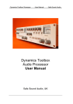
HP 8904A
MULTIFUNCTION SYNTHESIZER
(Including Options 001, 002, 003, 004, 005 and 006)
Operation and Calibration Manual
SERIAL NUMBERS
This manual applies directly to instruments with
serial numbers prefixed
2712A and all MAJOR changes that apply to your instrument.
rev.01JUL91
For additional important information about serial
numbers, refer to “INSTRUMENTS COVERED BY
THIS MANUAL”in Section 1.
Third Edition
This material may be reproduced by or for the U.S.
Government pursuant to the Copyright License under the clause at DFARS 52.227-7013(APR 1988).
Copyright@ HEWLETT-PACKARD COMPANY 1989
EAST 24001 MISSION AVENUE, TAF C-34, SPOKANE, WASHINGTON, U.S.A. 99220
Operation and Calibration Manual HP Part 08904-90007
Other Documents Availiable:
Operation and Application Guide HP Part 08904-90006
Service Manual HP Part 08904-90008
Microfiche OpetationKalibration Manual HP Part 08904-90019
Printed in U.S.A. : September 1992
HEWLETT
PACKARD
1 Regulatory Information
(Updated March 1999)
1
Regulatory Information (Updated March 1999)
Safety Considerations
GENERAL
This product and related documentation must be reviewed for familiarization with safety
markings and instructions before operation.
This product has been designed and tested in accordance with IEC Publication 1010,
"Safety Requirements for Electronic Measuring Apparatus," and has been supplied in a
safe condition. This instruction documentation contains information and warnings which
must be followed by the user to ensure safe operation and to maintain the product in a safe
condition.
SAFETY EARTH GROUND
A uninterruptible safety earth ground must be provided from the main power source to the
product input wiring terminals, power cord, or supplied power cord set.
SAFETY SYMBOLS
A
Indicates instrument damage can occur if indicated operating limits are exceeded.
&
Indicates earth (ground) terminal
A Indicates hazardous voltages.
WARNING
A WARNING note denotes a hazard. It calls attention to a procedure,
practice, or the like, which, if not correctly performed or adhered to,
could result in personal injury. Do not proceed beyond a WARNING
sign until the indicated conditions are fully understood and met.
CAUTION
A CAUTION note denotes a hazard. It calls attention to an operation
procedure, practice, or the like, which, if not correctly performed or adhered
to, could result in damage to or destruction of part or all of the product. Do
not proceed beyond an CAUTION note until the indicated conditions are fully
understood and met.
2
Chapter 1
Regulatory Information(Updated March 1999)
Safety Considerations for this Instrument
~
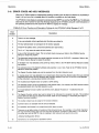
WARNING
This product is a Safety Class I instrument (provided with a
protective earthing ground incorporated in the power cord). The
mains plug shall only be inserted in a socket outlet provided with a
protective earth contact. Any interruption of the protective
conductor inside or outside of the product is likely to make the
product dangerous. Intentional interruption is prohibited.
Whenever it is likely that the protection has been impaired, the
instrument must be made inoperative and be secured against any
unintended operation.
If this instrument is to be energized via an auto transformer (for
voltage reduction), make sure the common terminal is connected to
the earth terminal of the power source.
If this product is not used as specified, the protection provided by
the equipment could be impaired. This product must be used in a
normal condition (in which all means for protection are intact) only.
No operator serviceable parts in this product. Refer servicing to
qualified personnel. To prevent electrical shock, do not remove
covers.
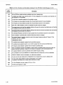
Servicing instructions are for use by qualified personnel only. To
avoid electrical shock, do not perform any servicing unless you are
qualified to do so.
The opening of covers or removal of parts is likely to expose
dangerous voltages. Disconnect the product from all voltage sources
while it is being opened.
The power cord is connected to internal capacitors that my remain
live for 5 seconds after disconnectingthe plug from its power supply.
For Continued protection against fire hazard, replace the line fuse@)
only with 250 V fuse(s)or the same current rating and type (for
example, normal blow or time delay). Do not use repaired fuses or
short circuited fuseholders.
Always use the three-prong ac power cord supplied with this
product. Failure to ensure adequate earth grounding by not using
this cord may cause product damage.
This product is designed for use in Installation Category I1 and
Pollution Degree 2 per ZEC 1010 and ZEC 664 respectively. FOR
INDOOR USE ONLY.
This product has autoranging line voltage input, be sure the supply
voltage is within the specified range.
Chapter 1
3
Regulatory Information (Updated March 1999)
To prevent electrical shock, disconnect instrument from mains (line)
before cleaning. Use a dry cloth or one slightly dampened with water
to clean the external case parts. Do not attempt to clean internally.
Ventilation Requirements: When installing the product in a cabinet,
the convection into and out of the product must not be restricted.
The ambient temperature (outside the cabinet) must be less than the
maximum operating temperature of the product by 4" C for every 100
watts dissipated in the cabinet. If the total power dissipated in the
cabinet is greater than 800 watts, then forced convection must be
used.
Product Markings
CE - the CE mark is a registered trademark of the European Community. A CE mark
accompanied by a year indicated the year the design was proven.
CSA - the CSA mark is a registered trademark of the Canadian Standards Association.
4
Chapter 1
CERTIFICATION
Hewlett-Packard Company certifies thut this product met its published specifications a t the time of shipment
from the factory. Hewlett-Packard further certifies that its calibration measurements are traceable to the United
States National Bureau of Standards, to the extent allowed by the Bureau’s calibration facility, and to the
calibration facilities of other International Standards Organization members.
WARRANTY
This Hewlett-Packard instrument product is warranted against defects in material and workmanship for a period
of one year from date of shipment. During the warranty period, Hewlett-Packard Company will at its option,
either repair or replace products which prove to be defective.
For warranty service or repair, this product must be returned to a service facility designated by HP. Buyer shall
prepay shipping charges to H P and H P shall pay shipping charges to return the product to Buyer. However, Buyer
shall pay all shipping charges, duties, and taxes for products returned to H P from another country.
H P warrants that its software and firmware designated by H P for use with an instrument will execute its
programming instructions when properly installed on that instrument. H P does not warrant that the operation
of the instrument, or software, or firmware will be uninterrupted or error free.
LIMITATION OF WARRANTY
The foregoing warranty shall not apply to defects resulting from improper or inadequate maintenance by Buyer,
Buyer-supplied software or interfacing, unauthorized modification or misuse, operation outside of the environmental
specifications for the product, or improper site preparation or maintenance.
NO OTHER WARRANTY IS EXPRESSED OR IMPLIED. H P SPECIFICALLYDISCLAIMS THE IMPLIED
WARRANTIES OF MERCHANTABILITY AND FITNESS FOR A PARTICULAR PURPOSE.
EXCLUSIVE REMEDIES
THE REMEDIES PROVIDED HEREIN ARE BUYER’S SOLE AND EXCLUSIVE REMEDIES. HP SHALL
NOT BE LIABLE FOR ANY DIRECT, INDIRECT, SPECIAL, INCIDENTAL, OR CONSEQUENTIAL
DAMAGES, WHETHER BASED ON CONTRACT, TORT, OR ANY OTHER LEGAL THEORY.
ASSISTANCE
Product maintenance agreements and other customer assistance agreements are available for Hewlett-Packard
products.
For any assistance, contact your nearest Hewlett-Packard Sales and Service Office.Addresses are provided at
the back of this manual.
SAFETY CONSIDERATIONS
GENERAL
This product and related documentation must be reviewed for familiarization with safety markings and
instructions before operation.
This product is a Safety Class I instrument (provided
with a protective earth terminal).
BEFORE APPLYING POWER
Verify that the product is set to match the available
line voltage and the correct fuse is installed.
SAFETY EARTH GROUND
An uninterruptible safety earth ground must be provided from the main power source to the product input
wiring terminals, power cord, or supplied power cord
set.
SAFETY SYMBOLS
Instruction manual symbol: the product will
be marked with t h i s symbol when i t
is necessary for the user to refer to the instruction
manual (refer to Table of Contents).
A
f
Indicates hazardous voltages.
Indicates earth (ground) terminal.
V
I
The WARNING sign denotes a
hazard. It calls attention t o a
procedure, practice, or the like, which, if not correctly
performed or adhered to, could result in personal injury. Do not proceed beyond a WARNING sign until
the indicated conditions are fully understood and met.
The CAUTION sign denotes a haza r d . I t calls attention t o an
operating procedure, practice, or the like, which, if not
correctly performed or adhered to, could result in damage to or destruction of part or all of the product. Do
not proceed beyond a CAUTION sign until the indicated conditions are fully understood and met.
A n y interruption of the protective (grounding) conductor (inside or outside the instrument) or disconnecting the protective earth
terminal will came a potential shock hazard
that could result in personal injury. (Grounding one conductor of a two conductor outlet
is not sufficient protection).
Whenever it is likely that the protection has
been impaired, the instrument must be made
inoperative and be secured against any unintended operation.
I f this instrument is to be energized via an
autotransformer (for voltage reduction) make
sure the common terminal is connected to the
earth terminal of the power source.
Servicing instructions are for use by servicetrained personnel only. To avoid dangerous
electric shock, do not perform any servicing
unless qualified to do so.
Adjustments described in the manual are performed with power supplied to the instrument
while protective covers are removed. Energy
available at many points may, if contacted, result in personal injury.
Capacitors inside the instrument may still be
charged even if the instrument has been disconnected from its source of supply.
For continued protection against fire hazard,
replace the line fuse(s) only with 250V fuse(s)
of the same current rating and type (for example, normal blow, time delay, etc.). Do not use
repaired f u s e s o r s h o r t c i r c u i t e d
fuseholders.
ATTENTION
Static Sensitive
Devices
This instrument was constructed in a n E S D (electro-static discharge) protected environment. This is because most of the semiconductor devices used in this instrument are susceptible to damage
by static discharge.
Depending on the magnitude of the charge, device substrates can
be punctured or destroyed by contact or mere proximity of a static
charge. The results can c a w e degradation of device performance,
early failure, or immediate destruction.
These charges are generated in numerous ways such as simple contact, separation of materials, and normal motions of persons
working with static sensitive devices.
W h e n handling or servicing equipment containing static sensitive
devices, adequate precautions must be taken to prevent device damage or destruction.
Only those who are thoroughly familiar with industry accepted
techniques for handling static sensitive devices should attempt to
service circuitry with these devices.
I n all instances, measures must be taken to prevent static charge
build-up on work surfaces and persons handling the devices.
For further information on E S D precautions, refer to “SPECIAL
HANDLING CONSIDERATIONS FOR S T A T I C S E N S I T I V E
DEVICES” in Section VIII Service Section.
Model 8904A
Volume 1 Contents
VOLUME 1 CONTENTS
Section 1 .General Information
A
Introduction . . . . . . . . . . . . . . . . . . . . . . . . . . . . . . . . . . . . . . . . . . . . . . . . . . . . .
Safety Considerations . . . . . . . . . . . . . . . . . . . . . . . . . . . . . . . . . . . . . . . . . . . . . . . .
Description . . . . . . . . . . . . . . . . . . . . . . . . . . . . . . . . . . . . . . . . . . . . . . . . . . . . .
Specifications . . . . . . . . . . . . . . . . . . . . . . . . . . . . . . . . . . . . . . . . . . . . . . . . . . . . .
Options . . . . . . . . . . . . . . . . . . . . . . . . . . . . . . . . . . . . . . . . . . . . . . . . . . . . . . . .
Mechanical and Document Options and Accessories . . . . . . . . . . . . . . . . . . . . . . . . . . . . . . .
Electrical Options . . . . . . . . . . . . . . . . . . . . . . . . . . . . . . . . . . . . . . . . . . . . . . . . . .
Option 001: . . . . . . . . . . . . . . . . . . . . . . . . . . . . . . . . . . . . . . . . . . . . . . . . . . . .
Option002: . . . . . . . . . . . . . . . . . . . . . . . . . . . . . . . . . . . . . . . . . . . . . . . . . . . .
Option 003: . . . . . . . . . . . . . . . . . . . . . . . . . . . . . . . . . . . . . . . . . . . . . . . . . . . .
Option 005: . . . . . . . . . . . . . . . . . . . . . . . . . . . . . . . . . . . . . . . . . . . . . . . . . . . .
Option006 . . . . . . . . . . . . . . . . . . . . . . . . . . . . . . . . . . . . . . . . . . . . . . . . . . . .
Hewlett-Packard Interface Bus . . . . . . . . . . . . . . . . . . . . . . . . . . . . . . . . . . . . . . . . . . .
Compatibility . . . . . . . . . . . . . . . . . . . . . . . . . . . . . . . . . . . . . . . . . . . . . . . . . . . .
Selecting the HP-IB Address . . . . . . . . . . . . . . . . . . . . . . . . . . . . . . . . . . . . . . . . . .
Accessories Supplied . . . . . . . . . . . . . . . . . . . . . . . . . . . . . . . . . . . . . . . . . . . . . . . . .
Recommended Test Equipment . . . . . . . . . . . . . . . . . . . . . . . . . . . . . . . . . . . . . . . . . .
Documentation Updating . . . . . . . . . . . . . . . . . . . . . . . . . . . . . . . . . . . . . . . . . . . . .
Serial Numbers . . . . . . . . . . . . . . . . . . . . . . . . . . . . . . . . . . . . . . . . . . . . . . . .
A Description of the Manual Update Packet . . . . . . . . . . . . . . . . . . . . . . . . . . . . . . . .
Signing Up for the Documentation Update Service . . . . . . . . . . . . . . . . . . . . . . . . . . . . .
11
.
12.
. 1-2
13
.
1-7
1-7
1-8
1-8
1-8
1-8
1-9
1-9
1-9
1-9
1-9
1-9
1-10
1-10
1-10
1-10
1-10
Section 2 .Installation
Introduction . . . . . . . . . . . . . . . . . . . . . . . . . . . . . . . . . . . . . . . . . . . . . . . . . . . . .
Initial Inspection . . . . . . . . . . . . . . . . . . . . . . . . . . . . . . . . . . . . . . . . . . . . . . . . . . .
Preparation For Use . . . . . . . . . . . . . . . . . . . . . . . . . . . . . . . . . . . . . . . . . . . . . . . . .
Line Voltage Selection and Fuse Replacement . . . . . . . . . . . . . . . . . . . . . . . . . . . . . . . .
Power Cables . . . . . . . . . . . . . . . . . . . . . . . . . . . . . . . . . . . . . . . . . . . . . . . . . . .
HP-IB Address Selection . . . . . . . . . . . . . . . . . . . . . . . . . . . . . . . . . . . . . . . . . . . .
Interconnection . . . . . . . . . . . . . . . . . . . . . . . . . . . . . . . . . . . . . . . . . . . . . . . . .
Mating Connectors . . . . . . . . . . . . . . . . . . . . . . . . . . . . . . . . . . . . . . . . . . . . . . .
Operating Environment . . . . . . . . . . . . . . . . . . . . . . . . . . . . . . . . . . . . . . . . . . . . .
Bench Operation . . . . . . . . . . . . . . . . . . . . . . . . . . . . . . . . . . . . . . . . . . . . . . . . .
Rack Mounting . . . . . . . . . . . . . . . . . . . . . . . . . . . . . . . . . . . . . . . . . . . . . . . . .
Storage And Shipment . . . . . . . . . . . . . . . . . . . . . . . . . . . . . . . . . . . . . . . . . . . . . . . .
Environment . . . . . . . . . . . . . . . . . . . . . . . . . . . . . . . . . . . . . . . . . . . . . . . . . . .
Packaging . . . . . . . . . . . . . . . . . . . . . . . . . . . . . . . . . . . . . . . . . . . . . . . . . . . . .
rev.OlNOV89
21.
21
.
21.
2-2
22.
22.
24.
24.
2-4
2-4
2-4
2-4
2-4
2-4
Volume 1 Contents
Model 8904A
Section 3 .
Operation
Introduction . . . . . . . . . . . . . . . . . . . . . . . . . . . . . . . . . . . . . . . . . . . . . . . . . . . . .
31.
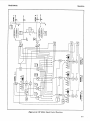
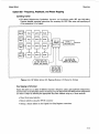
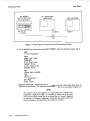
Block Diagram . . . . . . . . . . . . . . . . . . . . . . . . . . . . . . . . . . . . . . . . . . . . . . . . . . . .
32.
33.
Functional Block Descriptions . . . . . . . . . . . . . . . . . . . . . . . . . . . . . . . . . . . . . . . . .
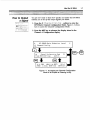
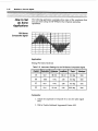
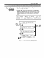
How to Create and Output a Signal . . . . . . . . . . . . . . . . . . . . . . . . . . . . . . . . . . . . . . .
-3-4
Instrument Functions and Operating Considerations . . . . . . . . . . . . . . . . . . . . . . . . . . . . . . .
3-6
36.
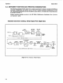
Standard Instrument: Creating a Simple Signal From Digital Data . . . . . . . . . . . . . . . . . . . . .
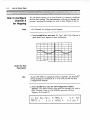
How the H P 8904A Generates a Signal . . . . . . . . . . . . . . . . . . . . . . . . . . . . . . . . . . . .
37.
37.
Operating Considerations: All Instruments . . . . . . . . . . . . . . . . . . . . . . . . . . . . . . . . . .
Abbreviated Channel A Specifications . . . . . . . . . . . . . . . . . . . . . . . . . . . . . . . . . . . . .
38.
Option 001 .Three More Channels, Summation, Modulation, and Sequencing . . . . . . . . . . . . . . 39.
Expanded Capabilities for Option 001 . . . . . . . . . . . . . . . . . . . . . . . . . . . . . . . . . . . .
3C-1
3-10
Operating Considerations: Option 001 . . . . . . . . . . . . . . . . . . . . . . . . . . . . . . . . . . . .
Abbreviated Specifications: Option 001 . . . . . . . . . . . . . . . . . . . . . . . . . . . . . . . . . . .
3-10
3-12
Option 002 .A Second Channel and Output . . . . . . . . . . . . . . . . . . . . . . . . . . . . . . . .
Operating Considerations: Option 002 . . . . . . . . . . . . . . . . . . . . . . . . . . . . . . . . . . . .
3-12
Abbreviated Specifications: Option 002 . . . . . . . . . . . . . . . . . . . . . . . . . . . . . . . . . . .
3-12
Option 003 .Frequency, Amplitude, and Phase Hopping . . . . . . . . . . . . . . . . . . . . . . . . . .
3-13
Operating Considerations: Option 003 . . . . . . . . . . . . . . . . . . . . . . . . . . . . . . . . . . . .
3-14
Abbreviated Specifications: Option 003 . . . . . . . . . . . . . . . . . . . . . . . . . . . . . . . . . . .
3-14
D i ~ t a l P.o. . . . . . . . . . . . . . . . . . . . . . . . . . . . . . . . . . . . . . . . . . . . . . . . . . . . .
3-15
General Information . . . . . . . . . . . . . . . . . . . . . . . . . . . . . . . . . . . . . . . . . . . . . .
3-15
3-15
Connector hnctions . . . . . . . . . . . . . . . . . . . . . . . . . . . . . . . . . . . . . . . . . . . . .
Remote Operation
. . . . . . . . . . . . . . . . . . . . . . . . . . . . . . . . . . . . . . . . . . . . 3-18
General Information . . . . . . . . . . . . . . . . . . . . . . . . . . . . . . . . . . . . . . . . . . . . . .
3-18
Programming Considerations . . . . . . . . . . . . . . . . . . . . . . . . . . . . . . . . . . . . . . . . .
3-18
HP-IB Compatibility . . . . . . . . . . . . . . . . . . . . . . . . . . . . . . . . . . . . . . . . . . . . .
3-19
3-19
HP-IB Code Listings for the H P 8904A . . . . . . . . . . . . . . . . . . . . . . . . . . . . . . . . . . .
3-31
Status Byte . . . . . . . . . . . . . . . . . . . . . . . . . . . . . . . . . . . . . . . . . . . . . . . . . . . . .
General Information . . . . . . . . . . . . . . . . . . . . . . . . . . . . . . . . . . . . . . . . . . . . . .
3-31
3-31
Using the Status Byte . . . . . . . . . . . . . . . . . . . . . . . . . . . . . . . . . . . . . . . . . . . . .
Error Isolation . . . . . . . . . . . . . . . . . . . . . . . . . . . . . . . . . . . . . . . . . . . . . . . . .
3-32
Error Codes and Help Messages . . . . . . . . . . . . . . . . . . . . . . . . . . . . . . . . . . . . . . . . .
3-34
3-37
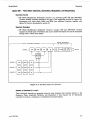
Special Functions . . . . . . . . . . . . . . . . . . . . . . . . . . . . . . . . . . . . . . . . . . . . . . . . . .
3-37
Introduction . . . . . . . . . . . . . . . . . . . . . . . . . . . . . . . . . . . . . . . . . . . . . . . . . .
Special 0: Last State Recalled on Power Up . . . . . . . . . . . . . . . . . . . . . . . . . . . . . . . . .
3-37
3-37
Special 1: Disable Automatic Phase Reset . . . . . . . . . . . . . . . . . . . . . . . . . . . . . . . . . .
3-37
Special 2: Disable Beeper . . . . . . . . . . . . . . . . . . . . . . . . . . . . . . . . . . . . . . . . . . .
Special 3: Reverse Modulating Waveforms . . . . . . . . . . . . . . . . . . . . . . . . . . . . . . . . .
3-37
3-38
Special 4: Disable Output Blanking . . . . . . . . . . . . . . . . . . . . . . . . . . . . . . . . . . . . .
3-38
Special 5: Floating Outputs on Power Up: . . . . . . . . . . . . . . . . . . . . . . . . . . . . . . . . . .
3-38
Special 6: Enable Synchronous mode: . . . . . . . . . . . . . . . . . . . . . . . . . . . . . . . . . . . .
Special 7: Configure as Master Controller: . . . . . . . . . . . . . . . . . . . . . . . . . . . . . . . . .
3-38
Operating Technical Reference . . . . . . . . . . . . . . . . . . . . . . . . . . . . . . . . . . . . . . . . . .
3-39
3-39
Waveform Jitter . . . . . . . . . . . . . . . . . . . . . . . . . . . . . . . . . . . . . . . . . . . . . . . .
3-39
Fine Amplitude Resolution . . . . . . . . . . . . . . . . . . . . . . . . . . . . . . . . . . . . . . . . . .
Filters . . . . . . . . . . . . . . . . . . . . . . . . . . . . . . . . . . . . . . . . . . . . . . . . . . . . . .
3-41
Phase Resolution . . . . . . . . . . . . . . . . . . . . . . . . . . . . . . . . . . . . . . . . . . . . . . .
3-42
3-42
Phase Continuous Switching . . . . . . . . . . . . . . . . . . . . . . . . . . . . . . . . . . . . . . . . .
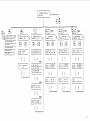
MenuMap . . . . . . . . . . . . . . . . . . . . . . . . . . . . . . . . . . . . . . . . . . . . . . . . . . . . .
3-44
3-44
Selecting Menus . . . . . . . . . . . . . . . . . . . . . . . . . . . . . . . . . . . . . . . . . . . . . . . .
Menu Changes When Using HP-IB Control . . . . . . . . . . . . . . . . . . . . . . . . . . . . . . . .
3-44
rev.01NOV89
Model 8904A
Volume 1 Contents
Hop RAM Sequencing . . . . . . . . . . . . . . . . . . . . . . . . . . . . . . . . . . . . . . . . . . . . . .
General Description . . . . . . . . . . . . . . . . . . . . . . . . . . . . . . . . . . . . . . . . . . . . .
Detailed Operation . . . . . . . . . . . . . . . . . . . . . . . . . . . . . . . . . . . . . . . . . . . . .
HP-IB Operation . . . . . . . . . . . . . . . . . . . . . . . . . . . . . . . . . . . . . . . . . . . . . .
FM Stereo Composite Generator . . . . . . . . . . . . . . . . . . . . . . . . . . . . . . . . . . . . . . . . .
General Description . . . . . . . . . . . . . . . . . . . . . . . . . . . . . . . . . . . . . . . . . . . . .
Detailed Operation . . . . . . . . . . . . . . . . . . . . . . . . . . . . . . . . . . . . . . . . . . . . .
HP-IB Operation . . . . . . . . . . . . . . . . . . . . . . . . . . . . . . . . . . . . . . . . . . . . . .
Multi-Instrument Phase Synchronization . . . . . . . . . . . . . . . . . . . . . . . . . . . . . . . . . . . .
Introduction . . . . . . . . . . . . . . . . . . . . . . . . . . . . . . . . . . . . . . . . . . . . . . . .
General Description . . . . . . . . . . . . . . . . . . . . . . . . . . . . . . . . . . . . . . . . . . . .
Electrical Connections . . . . . . . . . . . . . . . . . . . . . . . . . . . . . . . . . . . . . . . . . . . .
Detailed Operating Instructions . . . . . . . . . . . . . . . . . . . . . . . . . . . . . . . . . . . . . .
HP-E3 Operation . . . . . . . . . . . . . . . . . . . . . . . . . . . . . . . . . . . . . . . . . . . . . .
Specifications . . . . . . . . . . . . . . . . . . . . . . . . . . . . . . . . . . . . . . . . . . . . . . . .
High Power Balanced Output . . . . . . . . . . . . . . . . . . . . . . . . . . . . . . . . . . . . . . . . . .
Introduction . . . . . . . . . . . . . . . . . . . . . . . . . . . . . . . . . . . . . . . . . . . . . . . .
General Description . . . . . . . . . . . . . . . . . . . . . . . . . . . . . . . . . . . . . . . . . . . . . .
Operating Considerations . . . . . . . . . . . . . . . . . . . . . . . . . . . . . . . . . . . . . . . . . .
HP 8904A Option 006 Specifications . . . . . . . . . . . . . . . . . . . . . . . . . . . . . . . . . . . .
Expanded Capabilities for Option 001 . . . . . . . . . . . . . . . . . . . . . . . . . . . . . . . . . . . . . .
. 3C.l
3C-1
. 3C.l
. 3C5.
3C-7
3C-7
. 3C7.
3C-10
3A-1
. 3A.l
. 3A2.
3A-2
3A-3
. 3A7.
. 3A8.
. 3B.l
. 3B.l
3B-1
3B-1
3B-2
3C-1
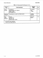
Section 4 .Performance Tests
Introduction . . . . . . . . . . . . . . . . . . . . . . . . . . . . . . . . . . . . . . . . . . . . . . . . . . . . .
Equipment Required . . . . . . . . . . . . . . . . . . . . . . . . . . . . . . . . . . . . . . . . . . . . . . . . .
Performance Test Record . . . . . . . . . . . . . . . . . . . . . . . . . . . . . . . . . . . . . . . . . . . . . .
Calibration Cycle . . . . . . . . . . . . . . . . . . . . . . . . . . . . . . . . . . . . . . . . . . . . . . . . . . .
Basic hnctional Checks . . . . . . . . . . . . . . . . . . . . . . . . . . . . . . . . . . . . . . . . . . . . . . .
Introduction . . . . . . . . . . . . . . . . . . . . . . . . . . . . . . . . . . . . . . . . . . . . . . . . . . . . .
Equipment Required . . . . . . . . . . . . . . . . . . . . . . . . . . . . . . . . . . . . . . . . . . . . . . . . .
Performance Test Record . . . . . . . . . . . . . . . . . . . . . . . . . . . . . . . . . . . . . . . . . . . . . .
Calibration Cycle . . . . . . . . . . . . . . . . . . . . . . . . . . . . . . . . . . . . . . . . . . . . . . . . . . .
Basic Functional Checks . . . . . . . . . . . . . . . . . . . . . . . . . . . . . . . . . . . . . . . . . . . . . . .
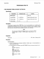
Performance Test 1 - AC and DC Amplitude Accuracy . . . . . . . . . . . . . . . . . . . . . . . . . . . . .
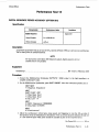
Performance Test 2 - AC Amplitude Flatness . . . . . . . . . . . . . . . . . . . . . . . . . . . . . . . . . .
Performance Test 3 - Spectral Purity . . . . . . . . . . . . . . . . . . . . . . . . . . . . . . . . . . . . . .
Performance Test 4 - Phase Accuracy . . . . . . . . . . . . . . . . . . . . . . . . . . . . . . . . . . . . .
Performance Test 5 - Channel-to-Channel Phase Accuracy (Option 001 . . . . . . . . . . . . . . . . . .
Performance Test 6 - Output l-to-Output 2 Phase Accuracy (Option 002) . . . . . . . . . . . . . . . . .
Performance Test 7 - Tone Sequence Timing Accuracy (Option 001) . . . . . . . . . . . . . . . . . . . .
Performance Test 8 - DTMF Sequence Timing Accuracy (Option 001) . . . . . . . . . . . . . . . . . . .
Performance Test 9 - Digital Sequence Period Accuracy (Option 001) . . . . . . . . . . . . . . . . . . .
rev.01 NOV89
4.1
4.1
4.1
4.1
4.1
41.
41.
4.1
4.1
41.
43.
44.
4-10
4-14
4-17
4-20
4-22
4-26
4-30
Volume 1 Contents
Model 8904A
Section 5 .
Adjustments
Introduction . . . . . . . . . . . . . . . . . . . . . . . . . . . . . . . . . . . . . . . . . . . . . . . . . . . . .
Safety Considerations . . . . . . . . . . . . . . . . . . . . . . . . . . . . . . . . . . . . . . . . . . . . . . . .
Equipment Required . . . . . . . . . . . . . . . . . . . . . . . . . . . . . . . . . . . . . . . . . . . . . . . . .
Post-Repair Tests, Adjustments, and Checks . . . . . . . . . . . . . . . . . . . . . . . . . . . . . . . . . . .
Adjustment 1 - Output Gain and Offset . . . . . . . . . . . . . . . . . . . . . . . . . . . . . . . . . . . . .
Adjustment 2 - Output Balance . . . . . . . . . . . . . . . . . . . . . . . . . . . . . . . . . . . . . . . . . .
Adjustment 3 - Output Gain (Option 006) . . . . . . . . . . . . . . . . . . . . . . . . . . . . . . . . . . . .
Adjustment 4 - Sharp Cutoff Low-Pass Filter . . . . . . . . . . . . . . . . . . . . . . . . . . . . . . . . . .
Adjustment 5 - Sine X/X Compensation . . . . . . . . . . . . . . . . . . . . . . . . . . . . . . . . . . . .
Adjustment 6 - Display Backlighting and Contrast . . . . . . . . . . . . . . . . . . . . . . . . . . . . . .
Adjustment 7 - Phase Synchronization (Option 005) . . . . . . . . . . . . . . . . . . . . . . . . . . . . .
5.1
5.1
5.2
25.
5-4
5.6
5.7
5.8
5-11
5-13
5-14
rev.OlNOV89
Model 8904A
General Information
Section 1
GENERAL INFORMATION
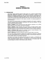
1-1. INTRODUCTION
This manual contains information required to install, operate, test, and adjust the Hewlett-Packard
Model 8904A Multifunction Synthesizer. The HP 8904A will generally be referred to as the
Multifunction Synthesizer throughout this manual. This manual documents standard Multifunction
Synthesizers and Multifunction Synthesizers supplied with four internal channels, Option 001, a
second output port, Option 002, Hop Ram capabilities, Option 003, and rear panel outputs, Option 004.
Operating and reference information for other options is provided in the operating supplements at
the end of section 3.
This section of the manual describes the instruments documented by this manual; it includes an
instrument description, options, accessories, specifications, and other basic information. The other
sections contain the following information:
Section 2, Installation: provides information about initial inspection, preparation for use, HP-IB
address selection for remote operation, and storage and shipment.
Section 3, Operation: provides information about panel features and includes operator’s checks,
operating instructions for both local and remote operation, and operator’s maintenance information.
Operating information for options after Option 004 is provided in the form of separate supplements.
Section 4, Performance Tests: provides the information required to check performance of the
instrument against the critical specifications listed in table 1-1.
Section 5, Adjustments: provides the information required to properly adjust the instrument.
One copy of the operating information is supplied with the Multifunction Synthesizer. An additional
copy of the Operating Manual may be ordered separately through your nearest Hewlett-Packard office.
Its part number is listed on the title page of this manual.
Also listed on the title page of this manual, below the manual part number, is a “Microfiche” part
number. This number may be used to order 100 x 150 millimeter (4- x 6-inch) microfilm transparencies
of this manual. Each microfiche contains up to 96 photo-duplicates of the manual’s pages. The
microfiche package also includes the latest Manual Updates information.
rev.OlNOV89
1-1
General Information
Model 8904A
1-2. SAFETY CONSIDERATIONS
This product is a Safety Class I instrument, that is, one provided with a protective earth terminal. The
Multifunction Synthesizer and all related documentation must be reviewed for familiarization with
safety markings and instructions before operation. Refer to the Safety Considerations pages found at
the beginning of this manual for a summary of the safety information. Safety information pertinent
to the task at hand, that is, installation, operation, performance testing, and adjustments, is found
throughout this manual.
1-3. DESCRIPTION
The HP 8904A is a Multifunction Frequency Synthesizer that produces six fundamental waveforms
to create complex signals. The waveforms available are: dc, sine wave, ramp (sawtooth), triangle,
square wave, and white (Gaussian) noise. The standard instrument is equipped with a single internal
channel and one output. The addition of available options can provide: a second signal output port,
three additional internal channels with modulation capabilities, and the ability to fast-hop between
different phase, frequency, and amplitude settings. Multi-instrument synchronization and high level
balanced output are also available.
A description of the available options is given in paragraphs 1-6 and 1-7.
1-2
reu.OlN0 V89
Model 8904A
General Information
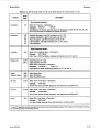
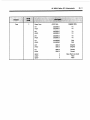
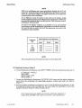
1-4. SPECIFICATIONS
n b l e 1-1. HP 8904A Specifications (1 of 4)
HP 8904A SPECIFICATIONS
Specifications describe the instruments' warranted performance (5oR output
only unless noted) for automatic operation. Mathematically derived characteristics denote parameters which can be derived from specifications and
knowledge of the digital generation methods used in the HP 8904A. Supplemental characteristics are intended to provide information useful in
applying the instrument by giving typical, but not warranted performance
parameters. These are noted as 'typical ",'normal", or 'approximate".
Frequency
Range: Sine wave: 0 Hz to 600 kHz.
Square, triangle, ramp: 0 Hz to 50 kHz.
Resolution: 0.1 Hz.
Accuracy: Internal 10 MHz timebase: 250 ppm.
External 10 MHz timebase: Same as accuracy and
stability of external timebase.
Supplementa 1 Characteristics
Number of channels: O n e standard; two with Option 002;
four with Option 002.
Standard waveforms: Sine, square, triangle, ramp, de, and
Gaussian white noise.
AC amplitude accuracy:
Typically: Square wave: <3% at 20 kHz.
Triangle : <4%. at 20 kHz.
Gaussian noise: <5%.
Ramp: <7% at 20 kHz.
Square wave risetime/falltime: Typically <2.5
ps.
Spurious (typically the higher of):
-50 dBc or 500 p V , 100 kHz to 600 kHz, 20 M H z BW.
Noise crest factor: fypically >4.4.
Switching speed (via HP-IB): Typically <25 ms.
AC amplitude (sine wave)
Range: 0 to 105 into a 5052 load.
Resolution: 3% &its.
Accuracy (amplitude >40 mVpp into 50Q):
1'30, 0.1 HZ to 100 kHz.
3%, 100 kHz to 600 kHz.
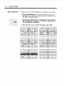
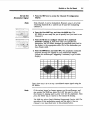
Flatness (amplitude >630
into 50Q):
+O.lYo (=0.009dB), 0.1 HZ to 100 kHz.
21.0% ( r 0 . 0 9 dB), 100 kHz to 600 kHz.
."
2+ -70 dB
n
X
F -80dB
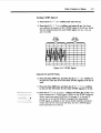
Spectral Purity (sine wave)
THD+N (including spurs, amplitude >50 mV rms into 5052):
-63 dBc I~TLS(0.07%), 20 HZ to 7.5 kHz, 30 kHz BW.
-63 dBc I~TLS(0.07%), 7.5 kHz to 20 kHz, 80 kHz BW.
-55 dBc I~TLS(0.18%), 20 kHz to 100 kHz, 750 ~ H BW.
Z
Phase (sine wave)
Range: 0 to 359.9O.
Resolution: 0.lo or 0.001 radians.
Increment accuracy (Relative to Oo for a fixed frequency):
20.05O, 0.1 Hz to 100 kHz.
Mathematically Derived Characteristics
Noise flatness (amplitude >lo0 mVp-p into 5052):
20.5 dB, 0.1 Hz to 100 kHz.
2 1.0 dB. 100 kHz to 600 kHz.
1
Noise Voltage /
Peak Voltage
fi = (Crest Factor) X 2 X hd%
rev.OlNOV89
VPk
(4.4)x (2) x
vmmi
1 kHz
100Hz
Frequency
10 kHz
100kHz
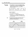
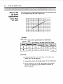
Typical Level Flatness ( I kHz ref.) at 5Vp-p into a 50R load.
+0.1 dB
I
I
I
1
LL
-0.1 dB
100Hz
Range: 0 to 21OV open circuit.
Resolution: 3% digits.
Accuracy: 520 mV or r2.1%, whichever is greater.
Gaussian Noise
10Hz
i
DC amplitude
'
0
Spectral Characteristic: Equal energy per unit bandwidth
("white").
Amplitude range: 0 to lo\, into a 5052 load.'
Resolution: 3% digits.
I
10 kHz
lkHz
100kHz
lMHz
I
10kHz
100kHz
Frequency
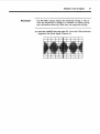
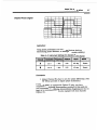
Typical SSB phase noise a t 500 kHz.
7
-
-80
-90
2 -100
\
V
% -110
-120
-130
-1401
1Hz
I
10Hz
I
100Hz
I
lkHz
Offset Frequency
1-3
I
Model 8904A
General Information
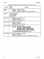
Ziable 1-1. HP 8904A Specifiatwns (2 of 4)
OPTION 001 SPECIFICATIONS
Supplemental Characteristics
Modulation
AM accuracy (at a 1 kHz rate and 600 kHz carrier):
(50Q outputs only)
Modulation for channel A ONLY, and specified for
sinewave carrier and modulation. Internal channels B, C,
and D can be used to either collectively modulate channel
A with one modulation type, or can provide simultaneous
modulation of channel A with any of the available modulation types. External modulation is NOT possible.
Amplitude Modulation (with Option 001)
Rate: 0 Hz to 600 kHz.
Depth range: 0% to 100% of carrier amplitude.
Resolution: 0.1% of carrier amplitude.
Frequency Modulation (with Option 001)
Rate: 0 Hz to 600 kHz.
Deviation range: 0 Hz up to 600 kHz, however
F,
+ Fdeviation
<=600 kHz.
Resolution: 0.1 Hz or 3% digits, whichever is less.
VOR bearing accuracy: Typically =0.059
Typically <t0.2%.
FM accuracy (at a 1 kHz rate, 20 kHz deviation, and
600 kHz carrier): Typically < 2 0.2%of setting.
Pulse modulation level accuracy: Typically 5% up to 20 kHz
pulse rate.
DSBSC carrier suppression: Typically >72 dB.
Intermodulation (two equal signal summed into one output):
Typically: <-70 dBc, for frequencies up to 100 kHz.
<-60 dBc, for frequencies 100 to 600 kHz.
Specifications for level accuracy, modulation accuracy, and
spectral purity are all referenced to the peak of the composite
signal less 3 dB. When signals are summed the specification for
each individual signal is degraded by its amplitude relative to the
peak of the composite signal.
FM Stereo Mode (with Option 001)
Pulse or DSBSC Modulation (with Option 001)
Test signal modes: Left = Right, Left = -Right, Left only, and
Right only.
Test tone frequency range: 20 Hz to 15 kHz.
Composite signal level: up to 10 Vp-pinto 50Q.
Pilot tone level: 0% to 100% of composite level.
Pilot tone level resolution: 0.1% of composite level.
Pilot tone frequency range: 0.1 Hz to 600 kHz
(default frequency 19 kHz).
Pilot tone phase adjustment range: 0.0 to 359.9O
Subcarrier frequency range: 0.1 Hz to 600 kHz
(default frequency 38 kHz).
Preemphasis: 25 psec, 50 psec, and 75 psec.
Summation (with Option 001)
Supplemental Characteristics
Phase Modulation (with Option 001)
Rate: 0 Hz to 600 kHz.
Range: Oo up to 179.9O/channel, however
Resolution: 0.lo or 0.001 radians.
Rate: 0 Hz to 50 kHz (up 600 kHz for DSBSC).
Two, three, or four channels may be summed into a single
output. Two or three channels may be summed for modulation of channel A. All combinations of channels are acceptable, EXCEPT FOR: { A+C and B+D ] or { A+D and B+C ]
at the same time.
Channel-to-channel phase accuracy (equal amplitude, sine
wave signals summed into one output): +0.lo or 30 ns ,
0.1 Hz to 100 kHz, whichever is greater.
Mathematically Derived Characteristics
AM accuracy (the higher of): 20.024% AM or 20.20% of
setting, up to 20 kHz modulation rate and 100 kHz carrier,
1%to 99% depth.
FM accuracy (the higher 00: 20.1 Hz or 20.28% of setting,
up to 20 kHz modulation rate, 20 kHz deviahon, and where
Fcarrier
+Fdeviation
<=lo0 kHz.
4M accuracy (the higher of): +0.lo or 20.28% of setting, up
to 20 kHz modulation rate, where:
DSBSC peak envelope accuracy: Same as amplitude accuracy,
up to 20 kHz modulation rate.
Phase accuracy when one channel is used to modulate
channel A (sine wave): 20.15O or 30 ns, whichever is greater,
0.1 Hz to 100 kHz carrier frequency.
1-4
FM stereo multiplex separation:
L-R: typically > 65 dB, audio frequency 20 H z to 15 kHz.
M-S: typically > 70 dB, audio frequency 20 Hz to 15 kHz.
Multiplex
subcarrier suppression: typically > 70 dB
.
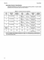
Tone Sequence (with Option 001)
Number of different frequencies: 16 user definable tones
each with an individual on time and off time.
On-time duration: 0 ms, 0.80 ms to 655.35 ms.
Off-time duration: 0 ms, 0.80 ms to 655.35 ms.
zero on time not allowed)
(Zero off time
Timing resolution: 0.01 ms (10 ps).
Timing accuracy: 20.02 ms (220 rs).
Sequence length 750 tones, user definable from front panel
or HP-IB programmable.
DTMF sequence (with Option 001)
Number of tone pairs: 16 standard DTMF tone pairs (0-9,
A-D, #, * ). Frequencies per Bell Technical Reference
Publication 48005.
On-time duration: 0 ms, 1.00 to 655.35 ms.
Off-time duration: 0 ms, 1.00 to 655.35 ms.
(Zero off time AND zero on time not allowed)
Timing resolution: 0.01 ms (10 rs).
Timing accuracy: 2 1ms.
Sequence length 750 DTMF tones, user definable from front
panel or HP-IB programmable.
rev.01NO V89
Model 8904A
General Information
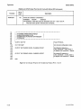
mble 1-1. HP 8904A Specifications (3 of 4)
Digital Sequence (with Option 001)
User definable:
On level (=lOV open circuit),
Off level ( 2 1OV open circuit), and period.
Sequence entry: Binary, octal, or hexidecimal.
Sequence length: Up to 3000 bits.
Period duration: 0.10 ms to 655.35 ms.
Period resolution: 0.01 ms (10 ps).
Period accuracy: 20.02 ms (= 20 ps).
Control modes (applies to tone, DTMF and digital sequence
modes): Manual sequence (allows stepping through sequence),
single sequence, and continuously repeat sequence.
Sequence can also be triggered by external TTL pulse.
Hop Ram Sequence (with Option 001)
Number of different States: 16 user definable states each with
an amplitude, frequency, and phase value.
Waveforms: Sine, square, ramp, triangle, dc, and white
Gaussian noise.
Sequence entry: Binary, octal, or hexidecimal.
Sequence length up to 3000 tones in binary mode (two states
used), or up to 750 tones in hex mode (all 16 states used).
Sequence clock frequency range: 0.1 Hz to 10 kHz.
Sequence clock frequency resolution: 0.1 Hz.
Sequence burst range: 1 repetition up to 127.
Control modes: Manual sequence (allows stepping through
sequence), burst sequence (1 to 127), and continuously
repeat sequence. Sequence can be triggered by external TTL
pulse.
OPTION 002 SPECIFICATIONS
(5052 outputs only)
Output 1 to Output 2 phase accuracy (sine waves at the
same frequency): k0.lo or 30 ns, 0.1 H z to ZOO kHz,
whichever is greater.
Supplemental Characteristics
O u t p u t 1 to O u t p u t 2 cross-talk (the higher
-100 dB or 20 IJY-,,0.1 H z to 20 kHz.
-95 dB or Z O p V , , 0.1 Hz to 100 kHz.
-90 dB OT 30 pq-,, 0.1 HZ to 600 kHz.
OD:Typically:
OPTION 003 SPECIFICATIONS
(5052 outputs only)
Direct addressing of channel A Up to 16 phase-frequencyamplitude states of channel A may be preset and directly
addressed with four TTL-compatible inputs. Timing for fast
hopping must be provided by an EXTERNAL source.
Digital modulation: By appropriately setting the 16 direct
control registers, the HP 8904A may be used as a digital
modulator. Examples of signals which can be generated
with this technique include FSK or multilevel FM (up to 16
levels), BPSK, QPSK, and QAM.
Supplemental Characteristics
Switching Speed:
Via digital port: Typically <8 CIS, <20 ps for full filter settling.
Via HP-IB: Typically <8 ms.
M a x i m u m switching r a t e (via d i g i t a l control port):
approximately 400 kHz.
M a x i m u m a l l o w a b l e address s k e w (via d i g i t a l port):
25 ns for valid results.
reu.01NOV89
OPTION 005 SPECIFICATIONS
(5052 outputs only)
Unit to unit phase accuracy: Additional 30 nsec error, 0.1 Hz
to 100 kHz. (Total phase error between units is then the
greater of 20.1 degree or 60 nsec, 0.1 Hz to 100 kHz.)
Maximum number of synchronized units: 8 units using
low-loss power splitters (for a total of 16 phase related
outputs if all units have Option 002).
Recommended power splitters:
5 4 units synchronized: Mini-Circuits model ZSC-4-3 or
equivalent.
1 8 units synchronized: Mini-Circuits model ZFSC-8-1 or
equivalent.
Supplemental Characteristics
Unit t o u n i t phase accuracy: typically < 15 nsec additional
error, 0.1 Hz to 100 kHz. r o t a 1 typical phase error between units
is then the greater of 20.1 degree or 30 nsec, 0.1 Hz to 100 kHz.)
OPTION 006 SPECIFICATIONS
(Sine wave only)
All specifications for the standard 50Q HP 8904A are degraded
by the accuracy, flatness, and distortion specifications of the
Option 006, 600Q transformer coupled output. Because the
transformer output was designed for passing sinewaves only,
all specifications apply to that waveform. The Option 006
output will not pass digital sequences available with Option
001. In addition, phase accuracy is degraded and therefore not
specified for Option 006.
Output type: fully floating/balanced transformer coupled output.
Usable output frequency range: 30 Hz to 200 kHz.
AC amplitude (sine wave only)
Range: Open circuit: 0 to 20 Vrms.
600Q load: 0 to 10 Vrms.
15052 load: 0 to 4 Vrms.
50Q load: 0 to 1.5 Vrms.
Resolution: 3% digits.
Accuracy (amplitude >40 mVrms into a balanced 6000 load):
6% (0.5 dB) 30 HZ to 20 kHz.
12% (1.0 dB) 30 Hz to 100 kHz.
Flatness (amplitude >40 mV rms into a balanced 600Q load,
1kHz reference):
0.15 dB, -0.15 dB, 30 HZ to 20 kHz.
+ 0.15 dB, -0.75 dB, 30 HZ to 100 kHz.
+
Spectral Purity (sine wave only)
+
THD N (including spurs, amplitude 140 mVrms to
10 Vrms into a balanced 600Q load):
-46 dB (0.50%), 30 Hz to 300 Hz, 30 kHz BW, amplitude
< 1 V, into a balanced 6000 load.
-60 dB (O.lOYo), 300 HZ to 7.5 kHz, 30 kHz BW.
-63 dB (0.07%), 7.5 kHz to 20 kHz, 80 kHz BW.
-55 dB (0.18%), 20 kHz to 100 kHz, 750 kHz'BW.
Supplemental Characteristics
Balance: Typically >40 dB, 30 H z to 50 kHz.
O u t p u t Impedance: Nominally 60OQ at 2 kHz.
Flatness (amplitude >40 mV rms into a balanced 60012 load,
1 kHz reference): + 0.15 dB, -4.0 dB, 30 H z to 200 kHz.
THD+N (including spurs, amplitude 240 mVrms to I Vrms info a
balanced 60OQ load):
<-50 dB (0.32%), 30 HZ to 300 Hz, 30 kHZ BW.
1-5
Model 8904A
General Information
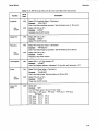
lbble 1-1. HP 8904A Specifications (4 of 4)
General
Store recall: 35 nonvolatile
Output type: Floating or grounded, HP-IB programmable.
Maximum float voltage (signal+float): 1OV peak maximum
from high or low side to chassis ground.
Zero-crossing outputs (available in Channel Config mode
only): For each channel, a TTL-compatible zero-crossing
output and polarity output are provided. The zero-crossing
output pulses high for approximately 600 ns each time the
channel phase goes through Oo or MOO. The polarity output
is high for phases of Oo to 180°, low for 180° to 360O.
These outputs do not reflect any user-specified phase offsets.
External timebase input: 10 MHz accepted at a nominal level
of 0.1 to 5V peak, automatic switching.
Timebase output: Output level >O dBm (0.3V peak) into a 50Q
load. Output signal will be the internal timebase unless an
external timebase is connected to the external timebase
input. When an external timebase is connected, it will be
routed to the timebase output connector.
Temperature: Operating, O°C to 5OOC;
Storage, - 2 O O C to 70OC.
Humidity range: 95% RH, O°C to 4OoC
Remote operation: HP-IB. All functions except the line switch
are remotely controllable.
HP-IB compatibility: SHl, AH1, T6, TEO, L4, LEO, SR1, RL1,
PPI, DCl, DTO, CO.
Power: 100/120V ( 2 10%); 48-440 Hz.
220/240V (& 10%); 48-66 HZ.
80 VA maximum.
Weight: Net 5.9 kg (12.8 lb.);
Shipping 13 kg ( 28.6 lb.).
Dimensions: 133 mm H X 213 mm W X 513 mm D
(5.25 X 8.36 X 20.2 inches).
HP System I1 size: 5%H X 1/z MW X 20 D.
EM1 Meets conducted and radiated interference of VDE 0871/
6.78 class B (radiated at 10 meters). Meets MIL 461B conducted (CE03) and radiated (RE02) interference.
Supplemental Characteristics
Output impedance: Typically 51K2 23%, 0.1 Hz t o 600kHz.
Note: Specifications for Option 005 and above are listed in the individual option supplements at the
end of section 3. (3A, 3B, 3C,..ETC.)
1-6
rev.01NOV89
Model 8904A
General Information
1-5. OPTIONS
NOTE
Refer to pages 2 and 3 of table 1-1 for a complete listing of specijications for
the electrical options.
Electrical and mechanical options are available and may have been ordered and received with the
Multifunction Synthesizer. The options are listed in paragraphs 1-6 and 1-7. These options may be
retrofitted to the instrument as follows:
To add Option 001, make arrangements with the nearest H P office to order HP part
number 11816A and have the option installed.
To add Option 002, order H P part number 11817A. The kit can be installed by the user or at an
H P Service Center.
To add Option 003, make arrangements with the nearest H P office to order HP part
number 11818A and have the option installed.
To change an instrument to Option 004, refer to the HP 8904A Service Manual’s section 7 Option
Conversions section for the necessary part numbers and procedure.
Note: Options 005 and 006 may only be retrofit on instruments with serial prefiz R948A and above. See
section 7 of the H P 8904A Service Manual for more information.
To add Option 005 (multi-instrument phase synchronization), order H P part number 11827A
from your local HP sales office. This option is not compatable with Option 004.
To add Option 006 (balanced output), order H P part number 11837A from your local HP sales
office. This option replaces the standard 500 output of Output 1.
1-6. MECHANICAL AND DOCUMENT OPTIONS AND ACCESSORIES
Rear-Panel Outputs : Option 004. The RF Output Connectors are located on the rear panel.
(Option 004 can not be installed with either Option 005, Phase Synchronization, or Option 006, High
Power Balanced Output.)
Extra Operating and Sewice Manuals (1 each) :Option 910. An additional Operation and Calibration
Manual and Service Manual are provided.
Add Sewice Manual :Option 915. The HP 8904A Service Manual provides the necessary procedures,
parts lists, component locators, troubleshooting aids, and schematic diagrams, to enable qualified
service personnel to repair an instrument. Information on retrofitting Options 002 and 004 is also
given.
Front Handle Kit. Ease of handling is increased with the front-panel handles. Order H P part number
5061-9689.
Bail Handle Kit. The bail handle attaches to the front of the instrument to provide easy portability.
Order HP part number 5061-9702.
Rack Flange Kit. This kit contains all necessary hardware and installation instructions for mounting
the Multifunction Synthesizer in a rack with 482.5 mm (standard 19-inch) by 133 mm (5.25 inch)
spacing. One side of the instrument mounts directly to the rack, an offset panel encloses the other
side of the opening. Order H P part number 5061-9657.
For more information on available mounting hardware and cabinet options, refer to the latest available
Hewlett-Pacbrd products catalog.
rev.OlNOV89
1-7
General Information
Model 8904A
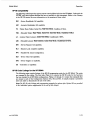
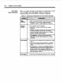
1-7. ELECTRICAL OPTIONS
Option 001:
Channel Configuration Mode Enhancements. Three additional individually-addressableinternal
channels are added for a total of 4 channels. The frequency, phase, amplitude, waveform, and
destination of each channel are individually defined by the user to provide the maximum flexibility of
the instrument. These additional channels provide the following functions:
Modulation of Channel A . Channels B, C, and D can be used to generate up to 3 independent forms
of modulation at the same time, or they can be summed prior to modulating channel A to generate
many complex waveforms. The allowable modulation types are: AM, FM, @M,DSBSC (Double Side
Band Suppressed Carrier), and pulse.
Channel Summation. Two, three, or four channels may be summed into a single output. Two or three
channels may be summed for modulation of channel A.
Tone Sequence Mode. Sixteen user-defined frequencies can be programmed into sequences. Both
the on and off times of each tone can be adjusted.
Dual lone Multi kequency (DTMF) Sequence Mode. The 16 standard Bell Telephone touch-tone
signals comma@ used in communications signaling can be output. Both the on and off times of each
tone can be user-defined.
Digital Sequence Mode. Digital data strings can be used in sequences to provide a series of signaling
events. Bit period and on/off levels can be user-defined.
Note: Hop RAM Sequence Mode and FM Stereo Composite Generator functions are only available
in Option 001 instruments with serial prefixes 2948A and above. Detailed operating information for
these functions is provided in section 3C.
Hop RAM Sequence Mode. Up to 16 different frequency, amplitude, and phase settings can be preset.
Sequences of up to 750 tones can be built using all 16 states. Sequences of up to 3000 tones can be
built using only two states. Sequences can be output from 1 to 127 times using a ‘burst’ function.
Timing is provided internally for the sequences and is adjustable for precise baud rates.
FM Stereo CompositeGenerator. A flexible FM stereo encoder function is added for testing broadcast
receivers. The audio test tone frequency, composite signal level, test signal mode, pilot on/off, pilot
amplitude, pilot frequency, pilot phase, carrier frequency, and preemphasis are adjustable.
Option 002:
A second internal channel and output port are added, allowing two independent, simultaneouslyoperating signals.
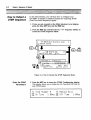
Option 003:
The DIGITAL PORT on the rear panel of the instrument allows direct TTL- input of control data to
perform the following functions:
Hop Ram. Up to 16 phase, frequency, and amplitude states of channel A may be preset and directly
addressed. Timing for fast hopping must be provided by an external source.
1-8
rev.OlNOV89
Model 8904A
General Information
Digital Modulation. Appropriately setting the 16 direct control registers allows the instrument to be
used as a digital modulator. Examples of signals which can be generated with this technique include
FSK or multilevel FM (up to 16 levels), BPSK, QPSK, and QAM.
Option 005:
Up to eight instruments may be connected together to form a “master/slave” relationship between the
instruments. One instrument provides the timing signals for the other seven. (If all eight instruments
are equipped with Options 002 and 005, a total of 16 outputs can be synchronized. If eight instrument
have Options 001 and 005,32 internal channels can be synchronized.) Detailed operating information
for this function is provided in the HP 8904A Option 005 supplement in section 3A.
Option 006:
A full-floating, balanced, transformer-coupled output is provided for Output 1. Output impedance is
6000 instead of the usual 50R. Maximum output level is increased to 20 V rms into an open circuit,
or 10 V rms into a 600R load. Detailed operating information for this function is provided in the
HP 89044 Option 006 supplement in section 3B.
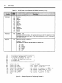
1-8. HEWLETT-PACKARD INTERFACE BUS
Compatibility
The Multifunction Synthesizer has an HP-IB interface and can be used with any HP-IB computing
controller or computer for automatic system applications. The Multifunction Synthesizer is fully
programmable via the HP Interface Bus. The Multifunction Synthesizer’s complete compatibility with
HP-IB is defined by the following list of interface functions: SH1, AH1, T6, TEO, L4,LEO, SR1, RL1,
PP1, DC1, DTO, and CO. The Multifunction Synthesizer interfaces with the bus via open collector
TTL circuitry. An explanation of the compatibility codes can be found in the IEEE Standard 488 and
the identical ANSI Standard MC1.l.
For more detailed information relating to programmable control of the Multifunction Synthesizer,
refer to Remote Operation, Hewlett-Packard Interface Bus in section 3 of this manual. A booklet
has been prepared entitled “Tutorial Description of the Hewlett-Packard Interface Bus” to provide
a complete overview of the theory and operation of HP-IB. To receive this booklet, order HP part
number 5952-0156.
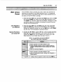
Selecting the HP-IB Address
The Multifunction Synthesizer’s HP-IB address is set by direct front-panel entry and is stored in nonvolatile memory. The instrument is delivered with address 26 already set, but may be easily changed
to any address desired from 00 to 30 (decimal). For information on changing the HP-IB address, refer
to paragraph 2-3 PREPARATION FOR USE, HP-IB Address Selection.
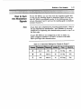
1-9. ACCESSORIES SUPPLIED
The power cable and fuse supplied for the Multifunction Synthesizer are selected at the factory
according to the Mains voltage available in the country of destination. For the part number and rating
of the fuse , refer to table 2-1. For the part numbers of the Power Cables and Mains Plugs available,
refer to table 2-2. Two BNC-to-Banana Plug adapters (HP Part 1250-2164) are shipped with each
standard instrument; four adapters are shipped with an Option 002 instrument.
rev.01NOV89
1-9
General Information
Model 8904A
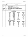
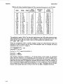
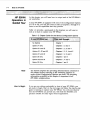
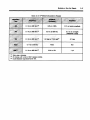
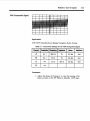
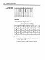
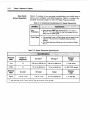
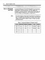
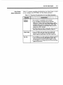
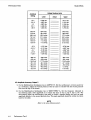
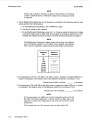
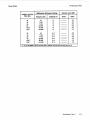
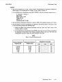
1-10. RECOMMENDED TEST EQUIPMENT
Table 2-1 lists the test equipment required for performance testing, adjusting, and servicing the
Multifunction Synthesizer. The Critical Specifications column describes the essential requirements
for each piece of test equipment. Other equipment can be substituted if it meets or exceeds these
critical specifications.
1-1 1. DOCUMENTATION UPDATING
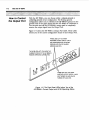
Serial Numbers
Attached to the instrument is a serial number plate. The serial number is in the form 1234A00123.
The first four digits and the letter are the serial prefix. The last five digits form the sequential suffix
that is unique to each instrument. The contents of these manuals apply directly to instruments having
the same serial number prefix(es) as listed under SERIAL NUMBERS on the respective manual
title pages.
For information concerning a serial number prefix not listed on the title page or in the Manual Update
packets, contact your nearest Hewlett-Packard office.
An instrument manufactured after the printing of these manuals may have a serial number prefix
that is not listed on the manual title page. Having a serial number prefix that is greater than that
shown on the title page indicates that the instrument is slightly different from those documented in
the manual. In this case, your manual is provided with updating information to make it as current as
possible. This updating information includes any hardware or software changes that have occurred as
well as corrections to the documentation.
A Description of the Manual Update Packet
A Manual Update packet consists of replacement and addition pages which should be incorporated in
your manual to bring it up to date.
Signing Up for the Documentation Update Service
Hewlett-Packard offers a Documentation Update Service that will provide you with further updates
and changes as they become available. If you have not received update information that matches the
serial number of your instrument, you can receive this information through the Update Service.
If you operate or service instruments with different serial prefixes, we strongly recommend that you
join this service immediately to ensure that your manual is kept current. For more information, refer
to the Documentation Update Service reply card included in this manual or contact:
Hewlett-Packard Company
Learning Products Department
24001 E. Mission-TAF C-34
Spokane, WA 99220
(509) 921-4001
Also, if you join the update service, you can indicate whether you choose to be contacted in the future
about the quality of the documentation you receive. We are trying to improve the documentation we
provide and periodically survey customers as to their expectations of the manuals.
1-10
rev.OlNOV89
Model 8904A
General Information
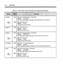
n b l e 1-2. Recommended Test Equipment (1 of 2)
Instrument
Type
Critical Specifications
Audio
Analyzer
~~
~~~
Fundamental Frequency Range: 20 Hz to 100 kHz
Distortion Range: -70 dB
DistortionAccuracy: f 2 dB
Low-Pass Filters: 30 and 80 kHz
~
-7Suggested
Model
HP 89038
,
I
1
Audio
Spectrum
Analyzer
Frequency Range: 100 to 5000 Hz
Input Level: 5 vims
Display Range: 60 dB
Digital
Multimeter
DC Range: 0 to 50V
DC Accuracy: &0.2%, 1 to 15 Vdc; f2 mV, 10 to 1000 mVdc
AC Range: 0 to lOOV
AC Accuracy: f l %
Ohms Range: 0 to 1 kR
Ohms Accuracy: f0.2%
HP 3478A
P, A
Frequency
Counter
Frequency Range: 10 MHz
Absolute Accuracy: f 5 ppm
HP 5314A
P
Network
Analyzer
Analyzer Frequency Range: 0 to 5 MHz
Display Range: 80 dB
Source Frequency Range: 0 to 5 MHz
Input and Output Impedance: 500
HP 3577A
A
Oscilloscope
3 dB Bandwidth: 1 MHz
Sensitivity: 5 mV per division
Input Impedance: 1 MR and 50R
Triggering: External and Internal
Two Channels; A vs. B Display
HP 1740A or
Tektronix 2235
Synthesized
Signal
Generator
Frequency Range: 1 kHz to 1 MHz
Output Level: 1 Vrms
Output Impedance: 50Q
Variable Phase Range: 360 deg
Variable Phase Resolution: 0.1 deg
HP 3325A
Option 001
HP 3561A or
HP 3580A
P
'P=Performance Tests;A=Adjustments
rev.01NOV89
1-11
Model 89MA
General Information
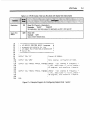
lhble 1-2. Recommended Test Equipment (2 of 2)
Instrument
Type
Critical Specifications
~~
Suggested
Model
~
Thermal
Converter
Level Range: 1V
Frequency Range: 20 Hz to 600 kHz
Flatness: f0.03O/0
Input Impedance: 50R
Multifunction
Synthesizer**
All specifications must match the HP 8904A Opt 005.
Power
Splitter**
(2 required)
Four way
Impedance: 50 R
Path Loss: 1 dB
Frequency Range: >50 MHz
~~~
I
HP 11050A or
Labs
1395A-1
~
HP 0904A
Option 005
Mini-Circuits
zsc4-3
*P=Perfotmance Tests; A=Adjustments
**Used only to test HP 8904A Option 005.
1-12
rev.01NOV89
Model 8904A
Installation
Section 2
INSTALLATION
2-1. INTRODUCTION
This section provides the information needed to install the H P 8904A Multifunction Synthesizer.
Included is infomation pertinent to initial inspection, power requirements, line voltage and fuse
selection, power cables, HP-lB address selection, interconnection, mating connectors, operating
environment, instrument mounting, storage, and shipment.
2-2. INITIAL INSPECTION
1-
To avoid hazardous electrical shock, do not peTform electrical tests when
there are any signs of shipping damage to any portion of the outer enclosure
(covers and panels).
Inspect the shipping container for damage. If the shipping container or cushioning material is
damaged, it should be kept until the contents of the shipment have been checked for completeness
and the instrument has been checked mechanically and electrically. Procedures for checking electrical
performance are given in Section 4. If the contents are incomplete, if there is mechanical damage or
defect or if the instrument does not pass the electrical performance test, notify the nearest HewlettPackard office. If the shipping container is damaged, or the cushioning material shows signs of stress,
notify the carrier as well as the Hewlett-Packard office. Keep the shipping materials for the carrier’s
inspection.
2-3. PREPARATION FOR USE
The Multifunction Synthesizer requires a power source of 100 to 12OVac (f10%) at 48 to 440 Hz, or
220 to 24OVac (zt 10%)at 48 to 66 Hz. Power consumption is 80 VA maximum.
I
I
This is a Safety Class I product @e., provided with a protective earth
terminal). An uninterruptible safety earth ground must be provided f r o m
the Mains power source to the product input wiring terminals, power cord,
or supplied power cord set. Whenever it is likely that the protection has
been impaired, the instrument must be made inoperative and be secured
against any unintended operation.
If this instrument is to be energized via a n external autotransformer for
voltage reduction, make sure that the common terminal is connected to the
earthed pole of the power source.
2-1
Installation
Model 89048
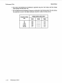
Line Voltage Selection and Fuse Replacement
BEFORE PLUGGING T H I S I N S T R U M E N T into the Mains (line) voltage,
be sure the correct voltage has been selected
A rear-panel switch permits operation from 100 to 120Vac when used i n the 115V position, or from
220 to 240Vac when used in the 230V position. The number visible on the switch indicates which
range of line voltage t o supply t o the instrument. Verify that the line voltage selection switch is
matched to the power source. Table 2-1 lists the ratings and the HP part number for the replaceable
fuse.
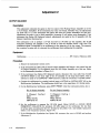
One fuse is supplied with each instrument. It has the proper rating for 100, 120, 220, or 240Vac
operation.
The fuse is installed in the instrument at the time of shipment. The position of the line voltage
selection switch is set according to the line voltage specified by the customer. If the voltage is not
specified, the selection switch will be set according to the country of destination.
Forprotection against fire hazard, the line fuse should only be a 250V fuse
with the correct current rating.
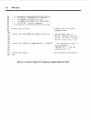
Table 2-1. Line Fuse Rating and HP Part Number
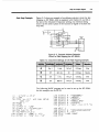
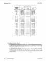
Power Cables
BEFORE CONNECTING THIS INSTRUMENT, the protective earth
terminal of the instrument must be connected to the protective conductor
of the (Mains) power cord. The Mains plug shall only be inserted in
a socket outlet provided with a protective earth contact. The protective
action must not be negated by the use of an extension cord (power cable)
without a protective conductor (grounding). Grounding one conductor of a
two-conductor outlet is not sufficient protection.
This instrument is equipped with a three-wire power cable. When connected to an appropriate ac
power receptacle, this cable grounds the instrument cabinet. The type of power cable plug shipped
with each instrument depends on the country of destination. Refer t o Table 2-2 for the part numbers
of the power cables and Mains plugs available.
2-2
rev.01JULSI
~
Model 8904A
Installation
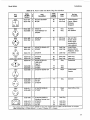
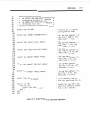
Table 2-2. Power Cable and Mains Plug Part Numbers
Plug
Type
Fl
8
D
Cable
Length
(inches)
Cable
Color
9oo/900
90
Mint Gray
Mint Gray
0
4
STR/STR
NZSS198/ASC112”
STR/90°
79
80
7
2
STR/STR’
STR/90°
6
STR/90°
Cable
HP Part
Number
D
8120-1351
8120-1703
4
8120-1369
8120-0696
Plug
Description
I
United Kingdom,
Cyprus, Nigeria,
Rhodesia,
Singapore
O
250V
6
\ I
A
125V
1oov
(Same plug as above)
250V
@y+
8
0
E
250V
8120-1689
8120-1692
8120-1378
8120-1521
8120-1751
8120-4753
8120-4754
8120-2104
6
fi
Jade Gray
Jade Gray
Jade Gray
8120-2296
8120-3997
8120-0698
8120-2956
8120-2957
8120-3997
3
3
4
STR/90°
STR/STR SEVl 011
1959-24507
Type 12
STR/90°
90
79
Dark Gray
I
I
”
0
8
8
United States,
STR/STR
Black
Gray
8120-1860
Japan only
Switzerland
Black
4
East and West
Europe, Saudi
Arabia, Egypt,
(unpolarized in
many nations)
United States,
Canada, Mexico,
Phillipines, Taiwan
U.S./Canada
79
8120-421 1
8120-4600
8120-1575
8120-2191
8120-4379
New Zealand
Mint Gray
Mint Gray
79
~~
00
250V
Ip
79
For Use
In Country
(Systems Cabinet Use)
STR/STR
STR/90°
90°/900
59
80
JadeGray
Jade Gray
Jade Gray
Jade Gray
I South Africa, India
I
I
2-3
Installation
Model 8904A
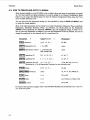
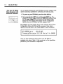
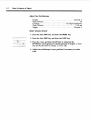
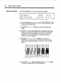
HP-lB Address Selection
The Multifunction Synthesizer is both a listener and a talker. Any address from 00 to 30 (decimal)
can be used, however, address 21 should not normally be used since it is the address normally
reserved for the internal controller. HP-IBaddresses greater than 30 are invalid and will not be
allowed to be stored in the instrument. The instrument will normally be delivered with the HP-IB
address set to 26.
The HP-II3 address c a n only be changed while the instrument is on, and by using direct front panel
entry. To read o r change the HP-IB address, key-in SHIFT ADRS. The front panel will display the
current address and allow the entry of a new address. Enter a new HP-IB address by keying-in the
new address and pushing the ENTER key.
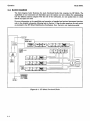
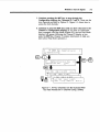
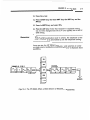
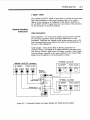
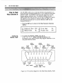
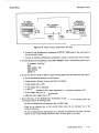
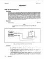
interconnection
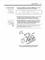
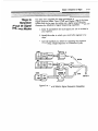
Interconnection data for the Hewlett-PackardInterface Bus is provided in Figure 2-1.
Mating Connectors
Coaxial Connectors. Coaxial mating connectors used with the Multifunction Synthesizer should
be 50-ohm BNC male connectors that are compatible with those specified in US MIL-C-39012.
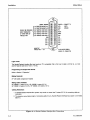
Interface Connector. HP-IB mating connector is shown in Figure 2-1. Note that the two securing
screws are metric.
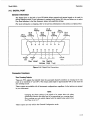
DIGITAL PORT Connector. This is a 15 circuit, 15 pin, type "D" subminiature connector.
Corresponding mating connector is HP part 1251-0221 o r TRW part DAM15P. (The Hop Ram
functions for the port only operate on instruments equipped with Option 003 - Hop Ram).
Operating Environment
The operating environment should be within the following limitations:
Temperature ............................................................................
.O" C to + 50" C
Humidity ....................................................................... < 95%relative at 40" C
Altitude.. ...................................................................
.< 4570 meters (15,000 feet)
Bench Operation
The instrument cabinet has plastic feet and a foldaway tilt stand for convenience in bench operation.
(The plastic feet are shaped t o ensure self-alignmentof instruments when they are stacked.) The tilt
stand raises the front of the Multifunction Synthesizer for easier viewing of the front panel.
Rack Mounting
Rack mounting information is provided with the rack mounting kits. If a kit was not ordered with
the Multifunction Synthesizer as an option, it may be ordered through the nearest Hewlett-Packard
office.
2-4
rev.OIJULSI
Model 8904A
Installation
2-4. STORAGE AND SHIPMENT
Environment
The instrument should be stored in a clean, dry environment. The following environmental
Limitations apply to both storage and shipment.
+
Temperature .......................................................................... -20' C to 75' c
Humidity .......................................................................
< 95% relative at 40' C
Altitude.. ..................................................................
c 15 300 meters (50,000 feet)
Packaging
Original Packaging. Containers and materials identical to those used in factory packaging are
available through Hewlett-Packardoffices. If the instrument is being returned to Hewlett-Packard
for servicing, attach a tag indicating the type of service required, retum address, model number,
and full serial num ber. Also, mark the container FRAGILE to assure careful handling. In any
correspondence, refer to the instrument by model number and full serial number.
Other Packaging. The followinggeneral instructions should be used for repackaging with commercially available materials.
a. Wrap the instrument in heavy paper or plastic. (If shipping t o a Hewlett-Packard office or
service center, attach a tag indicating the type of service required, return address, model
number, and full serial number.)
b. Use a strong shipping container. A double-wall carton made of 2.4 MPa (350 psi) test material
is adequate.
c. Use enough shock-absorbing material (75 to 100 millimeter layer; 3 to 4 inches) around all
sides of the instrument to provide a fjrm cushion and to prevent movement in the container.
Protect the front-panel with cardboard.
d. Seal the shipping container securely.
e. Mark the shipping container FRAGILE to assure careful handling.
rev. 01JUL91
2-5
Installation
Model 8904A
SHOULD BE GROUNDED
NEAR TERMINATION
OF OTHER WIRE OF
TWISTED PAIR
P/O W S T E O PAIR WITH 11
P/O TWISTED PAIR WITH 10
P/O TWISTED PAIR WITH 9
P/O TWISTED PAIR WITH 8
P/O TWISTED PAIR WITH 7
P/O TWISTED PAIR WITH 6
REN
DIO 8
Dl0 7
DIO 6
DIO 5
ISOMETRIC
THREAD M3.5
X
0.6
SHIELD -CONNECT
TO
ATN
EARTH
SRO
GROUND
IFC
NDAC
NRFD
DAV
EO1
DIO 4
Dl0 3
DIO 2
DIO 1
24-PIN MICRO-RIBBON
(SERIES 57) CONNECTOR
Logic Levels
The Hewlett-Packard Interface Bus logic levels are TTL compatible, that is, the true (1) state is 0.0 Vdc to f0.4 Vdc
and the false (0) state is 2.5 Vdc to +5 Vdc.
Programming and Output Data Format
Refer to Section 3 “Operation”.
Mating Connector
HP 1251-0293; Amphenol57-30240
Mating Cables Available
HP 10833A, 1 meter (3.3 ft.), HP 108338 2 meters (6.6 ft.)
HP 10833C 4 meters (13.2 ft.), HP 108330, 0.5 meters (1.6 ft.)
Cabling Restrictions
1. A Hewlett-Packard Interface Bus system may contain no more than 2 meters (6.6 ft.)of connecting cable per
instrument.
2. The maximum accumlative length of connecting cable for any Hewlett-Packard Interface Bus system is 20 meter
(65.6 ft.).
Figure 2-1. Hewlett-Packard Interface Bus Connections
2-6
rev. 15MAY89
Model 8904A
Operation
Section 3
OPERATION
3-1. INTRODUCTION
This section provides reference information for operating the HP 8904A Multifunction Synthesizer
by manual or remote control. Information is given that helps you understand how the H P 8904A
generates signals, and what you must know in order to create the signal you need.
‘Button-by-button’ and tutorial operating instructions for options 001, 002, and 003 are provided in
the HP 8904A Operation and Application guide.
Note: Option 001 capabilities have been expanded for instruments with serial prefix 2948A and
above. Detailed operating and HP-1B information for these functions is provided in section 3C.
Operating information for options 005 and 006 is provided in sections 3A and 3B.
The capabilities and specifications for the various options, HP-Il3 operation and codes, and other
reference information is given under the following headings:
Instrument Block Diagram - provides an overview of the main functional blocks that comprise the
HP 8904A.
How to Create and Output a Signal - illustrates how the different signal controls are implemented in
the instrument and the control sequences used to create and output a signal.
Instrument Functions and Operating Considerations - describes the capabilities and operating
considerations for a standard HP 8904A and the various options.
Digital Port - identifies the connections for this port and describes how it is used for operations such
as fast hopping Option 003 equipped instruments.
Remote Operation - lists the HP-IB codes and capabilities implemented in the HP 8904A.
Programming examples are given to illustrate the usage of some of the codes listed for each option.
Status Byte - discusses the purpose and use of the Status Byte. Programming examples are given to
help you further understand and apply the information.
Error Codes and Help Messages - lists the various error codes and their meanings.
Special Functions - describes the special functions in the H P 8904A and how to program them.
Operating Technical Reference - provides detailed technical descriptions for a variety of topics related
to operating the HP 8904A.
Menu Map - illustrates the organization of the various menus used in the H P 8904A and what
keystrokes are used to access each of the menus. This fold-out page is designed to be viewed as you
refer to the other material that is listed earlier in the section, letting you see a ‘before and after’
relationship between the menus and the related operations.
rev.01NOV89
3-1
Model 8904A
Operation
3-2. BLOCK DIAGRAM
The block diagram below illustrates the main functional blocks that comprise the HP 8904A. The
capabilities of your instrument are dependant upon the options you have ordered. By understanding
how the different options integrate with the rest of the instrument, you can quickly learn to create
almost any signal you need.
For more information on the capabilities and operation of standard and optional instrument functions,
refer to the detailed information following later in Section 3. Step-by-step operations for each option
are included in the HP 8904A Multifunction Synthesizer Basic Operation and Application guide.
I I
I I
I I
I
1
Figure 3-1. HP 8904A finctional Blocks
3-2
Model 8904A
Operation
Functional Block Descriptions
CPU: The Central Processing Unit consists of the microprocessor, Numeric Synthesis IC, and
the associated ROM and RAM memories needed to store the instruments operating system and
configuration settings. Interfacing between the HP-JB, Digital Port, and keyboard inputs is performed
here.
Recall/Save Registers: This is a special section of RAM that is used to store instrument settings
for later retrieval. A battery backup is provided so that the information in this memory is not lost if
power is disconnected from the instrument.
Hop RAM Registers: This is the area of RAM where the 16 Hop RAM settings are stored for
Option 003 equipped instruments.
Digital Port: The Digital Port connector on the rear panel of the HP 8904A is used primarily for
address selection and timing of the Hop RAM settings. Fast hopping is achieved by using an external
timing signal. The usage of this connector is discussed later in Section 3, along with more details on
using Option 003.
Keyboard: All of the front panel controls.
HP-IB: This is the connector for the IEEE-488 compatible Hewlett-Packard Interface Bus. Except
for the Line switch, all functions that can be selected using the front panel controls can be selected
remotely over this control bus. Refer to the Remote Control information described later in Section 3
for more information regarding the use of this connection. Example programs for using the HP-IB are
also provided.
Standard Single Channel: This block contains the one standard channel included with every
instrument (channel A). You can control the Frequency, Phase, Amplitude, and Waveform of the signal.
Option 001: Three more channels are added. You may s u m channels together in various combinations.
(Refer to the Option 001 Specifications listed in Section 1 for more information on summation.)
Modulation of channel A is provided using one or more of the other channels as a modulating source.
Sequencing of Tone, DTMF (Dual Tone Multi Frequency), and Digital signals is provided.
Option 002: A second channel (channel B) and a second instrument output port are added. The two
channels operate independent of each other; however, the phase relationship between the two signals
can be varied by adjusting either channel.
Option 003: This feature provides the ability to hop between 16 different channel A setups. Frequency,
Amplitude, and Phase can all be hopped simultaneously or independently. The timing signal and address
selection for accomplishing the hopping is input via the Digital Port. (See Digital Port discussed earlier
in this section.)
3-3
Operation
Model 8904A
3-3. HOW TO CREATE AND OUTPUT A SIGNAL
Each channel available in your HP 8904A is set to default values each time the instrument is powered
up. You must specify any signal parameters you need to change in the Channel Configuration Mode
before you can output the desired signal. To enter the Channel Configuration Mode, press the f l key
from the Main Selection Level.
You can then store the instrument settings you have specified by using the SAVE and RECALL keys
to access the storage registers.
Most of the signal parameters can be entered in any order. (Destination, Frequency, Phase, Amplitude;
Destination, Amplitude, Frequency, Phase.. etc.) However, you should always set the Destination
(DESTN) before specifying the Amplitude (AMPTD); since the Amplitude setting is always set to
zero (0)when the Destination is changed. If you turn the Destination Off for any channel, you can not
change the amplitude for that channel until it is turned back On.
*
+
Value(Ezample)
IFREQI (frequency)
2 0 (0,1.8, 24 ...)
Hz, kHz
1,2, or OFF
(none)
1,2, AM, FM, 4M,
DSB, PULSE,OFF
(none)
Parameter
Im](destination) ch A
1(destination) ch B,C,D
IAMPTD](amplitude) AC
1-1
(amplitude) DC
Terminator
2 0 (9,2.18, .Ol...)
f (-1.1,-9,9.07... )
(amplitude) ch B,C,D 2 0 ( I , 94, .07...
Modulating ch A. Use the appropriate Terminator for each modulation type.
1-
(phase)
1(waveform)
ml(float)
1-1
(filter)
p m q (output)
>O
(0,1.8, .6...)
rad, deg
+,E\I, 'L,NOISE, =
(none)
'L,
1 or 2
ON or OFF
1 or 2
Low Overshoot or Sharp Cutoff
1 or 2
ON or OFF
For step-by-step operation examples, refer to the HP 8904A Multifunction Synthesizer Basic Operation
and Application guide.
3-4
Model 8904A
Operation
c
1
L
Figure 3-2.HP 8904A Signal Control finctions
3-5
Operation
Model 8904A
3-4. INSTRUMENT FUNCTIONS AND OPERATING CONSIDERATIONS
The following paragraphs briefly explain how a signal is generated, the features included with different
instrument configurations and options, and an overview of special operating considerations for each
case. Abbreviated specificationsare also included for quick reference. (A detailed list of all specifications
is provided in Section 1.)
Detailed operating examples are given in the HP 8904A Multifunction Synthesizer Basic Operation
and Application guide.
Standard Instrument: Creating a Simple Signal From Digital Data
FREO DATA
CLOCK
I
DAC
-
P0
PHASE
ADJUST DATA
C-D
0
P
>
WAVEFORM
TABLE DATA
*-Is-x4
4
AHPL I TUDE
MULITIPLIER
I -
SAMPLER
AMPLITUDE
DATA
SAMPLER
FILTER CONTROL
AUDIO
R O A T I NG
OUTPUT
ANALOG CONVERSION AND CONDITIONING
Figure 3-3. Creating A Simple Signal
3-6
~
DESTINATION
CONTROL
( ON/OFF )
ATTEN 1
\
DI GITAL
~
~
~
~
OUTPUT 1
ATTEN 2
OVER
VOLTAGE
/
CONTROL
(ON/OFFI
~
L
Model 8904A
Operation
How the HP 8904A Generates a Signal
Waveforms are generated by a numerical synthesis technique. The heart of the synthesizer is a single
digital waveform synthesis integrated circuit (DWSIC). For each channel, the DWSIC generates a
continuous stream of numbers which represent instantaneous levels of the waveform. These digital
values are then converted to an analog signal by a digital-to-analog converter or DAC (one converter
for each output port).
The analog signal is conditioned by conventional analog circuitry and routed to the output connector.
The conditioning circuits include a sample-and-hold to remove DAC switching noise, filters to remove
quantization noise (smooth the transitions between samples from the DAC), amplifiers to boost the
maximum output, and attenuators to increase the outputs dynamic range.
For more detailed information on how the HP 8904A creates signals, refer to the HP 8904A
Multifunction Synthesizer Service Manual.
Operating Considerations: All Instruments
Amplitude Resolution
The amplitude resolution of the HP 8904A is provided by a combination of digital and analog controls
and can be specified in smaller increments than what is displayed on the front panel of the instrument.
Because of this method of adjustment, the amplitude resolution varies between output voltage levels.
Refer to the Operating Technical Reference: Amplitude Resolution information included later in Section 3
if you need more information regarding very fine amplitude adjustments.
Floating Output
The HP 8904A is designed to allow the user to have a floating ground that is independent of the
chassis ground of the instrument. This is why there is a LOW and HIGH connection for each output.
You may also prefer a ‘normal’ chassis referenced ground for your application, using the shield of the
HIGH connector for the ground reference.
The FLOAT control allows you to select the type of signal reference you require. The instrument always
powers up in the ‘floating ground’ mode. If you have specified the correct output destination and
amplitude for a signal, and there appears to be no signal present on the output, check to see that you
have specified the correct ground reference for your application.
Waveform Jitter
Due to the digital conversion process used to create the different waveforms in the HP 8904A, a partial
waveform can be present when using a ramp, square, or triangle waveform. This type of distortion is
referred to as ‘jitter’. This affect can be seen by displaying a 48 kHz square wave on an oscilloscope.
The highbow transition period appears to have a second offset trace. For more information on what
causes this affect, refer to the Operating Technical Reference: Waveform Jitter information included
later in Section 3.
3-7
Operation
Model 8904A
Abbreviated Channel A Specifications
Abbreviated specifications are listed here to provide general operating guidelines. Complete detailed
specifications for all instrument options are listed in Section 1.
3-8
Model 8904A
Operation
Option 001 - Three More Channels, Summation, Modulation, and Sequencing
Operating Tutorial
0
HP 8904A Multifunction Synthesizer Operation and Application guide (HP part 5953-8491):
most of the capabilities provided by Option 001.
Contains detailed operating instructions for Instruments with serial prefix 2948A and above have additional functions available with
Option 001 that are documented in section 3C.
Waveform Examples
0
H P 8904A Multifunction Synthesizer Waveform Catalogue (HP part 5953-8494): Contains
examples of several types of waveforms that can be created with Option 001 and the instrument
settings used to obtain those signals.
1-
DIGITAL WAVEFORM SYNTHESIS
CHANNEL A
fRCo
-0
PHASE
r-
ANALOG CONVERSION
AND CONDITIONING
D/A
F,LTERS
ATTEN-
1
AMPLI-
I
AM. FM.W
DSE. PULSE
z
CHANNEL
B
fRm
PHASE -m
AMP
lab
PHASE
CHANNEL D
PHASE
Figure 3-4. HP 8904A Option 001 Operation
Addition of Channels 6, C, and D
These additional channels are generated using the same technique that provides channel A. The
Frequency, Phase, Amplitude, Waveform, and Destination of each channel can be individually
controlled to produce a combination of modulated and summed signals.
reu.01NOV89
3-9
Model 8904A
Operation
Summation
You can sum two, three, or four channels together into a single output. You can sum two or three
channels together to produce a composite modulation signal for modulating channel A. For instance,
you could use channels B and C to modulate channel A, and then s u m channel D with the modulated
channel A signal. (Refer to Operating Considerations: Summation for additional information.)
Modulation
You can use one or more of the three additional channels to modulate channel A. (Only channel A can
be modulated.) Multiple channels can be summed together to provide composite modulation signals;
such as those used for FM Stereo broadcasts or VOR Navigation. (Refer to Operating Considerations:
Summation for additional information on summing modulating signals.)
External modulation is not provided.
Sequencing
Sequencing allows you to output a sequence of Tone, DTMF (Dual Tone Multi Frequency), or Digital
signals. Each of the individual signals in a sequence can be defined to provide very exacting signaling
capabilities. Sequencing can be set to run continuously, or one sequence at a time using manual control.
Tone Sequencing - You can specify up to 16 individual tones; creating a sequence of up to 750 tones.
You can adjust the order of the tones to appear in any sequence. The Frequency, On Time, and Off
Time of each tone can be individually set.
DTMF Sequencing - The DTMF signals are the same as those used for tone-type telephone
communications. Sixteen different DTMF signals are available for creating a sequence of up to 750
tones. You can adjust the order of the tones to appear in any sequence. The On Time and Off time of
each tone can be individually set.
Digital Sequencing - Digital sequencing allows you to specify a series of digital on/off values to be
output. The Sequence Base, Period, On Level, and Off Level are adjustable. Sequences of up to 3000
bits values may be specified.
Hop RAM Sequencing - Hop RAM sequencingoffers a combination of the capabilities of tone and digital
sequence modes. Sixteen signal states can be preset, each with an associated amplitude, frequency,
and phase value. Sequences of up to 750 tones can be output if all sixteen output states (Hexadecimal)
are used. Sequences of up to 3000 tones can be output if only two output states (Binary) are used.
FA4 Stereo - The FM Stereo composite generator mode,allows the user to test FM broadcast stereo
receivers. All of the associated FM stereo signal parameters are adjustable for maximum flexibility.
Operating Considerations: Option 001
Summation
Summation may be done using many combinations of signal output and modulation schemes.
All combinations of channel summation are acceptable, EXCEPT FOR [A+C and B+D] or
[A+D and B+C] at the same time. (You may not sum two sets of non-adjacent channels.) However,
you can sum and output two adjacent channels, such as B+C, and modulate channel A with the
non-adjacent channel D.
Abbreviated Specifications: Option 001
Abbreviated specifications are listed here to provide general operating guidelines. Complete detailed
specifications for options 001 to 003 are listed in Section 1. Specifications for Option 005 and above
are provided in supplements at the end of this section.
3-10
rev.OlNOV89
Model 8904A
Operation
Modulation of channel A only; using a sinewave carrier and modulating signal.
I
Modulation
Rate
Range
Resolution
AM
0 Hz to 600 kHz
1% to 100%
of carrier amplitude
0.1%
of carrier amplitude
FM
0 Hz to 600 kHz
0 Hz to 600 kHz
0.1 Hz or 34 digits,
whichever is less
QIM
0 Hz to 600 kHz
OOup to 179.9'
per channel
0.1Oor 0.001 radians
Pulse
0 Hz to 50 kHz
(N/A)
DSBSC
0 Hz to 600 kHz
OVTOlOV
Sequence
Type
Signal
Format
Number of Different
Signals
Tone
Single Frequency
Tones
Dual Tone
Multi Frequency
Binary, Octal or
Hexadecimal codes:
Output Serially
Single Freq. Tones
Hexadecimal, Octal,
or Binary Codes
DTMF
Digital
Hop RAM
rev.01NOV89
16 different userdefined frequencies
16 standard DTMF
tone pairs (0-9,A-D,#,')
16 (0-F Hex)
16 (0-F Hex)
(N/A)
3f digits
Maximum
Sequence Length
250 tones
250 tones
250 Cbit words
(1000 bits)
750 Cbit words
(3000 bits)
3-1 1
Operation
Model 8904A
-
Option 002 A Second Channel and Output
NOTE
The following description pertains to instruments with Option 002 only.
Addition of Option 001 provides more flexibility for wing the second channel
and output.)
Channel B and Output 2 Are Added
The second channel and output added by Option 002 are identical in function and operation to the
standard single channel and output included with all instruments.
The Frequency, Amplitude, Phase, and Waveform of channel B are controlled separately from channel A,
allowing you to output two completely different signals at once. The Outputs for the two channels are
also independently controlled. The phase relationship between the two channels is precisely controlled
and can be altered by adjusting the Phase of either channel.
Operating Considerations: Option 002
Destination Control
Option 002 does not allow you to change the Destination of the two channels. Channel A is always
designated for Output 1; Channel B is always designated for Output 2. (See note above.)
Abbreviated Specifications: Option 002
The specifications for channel B are identical to those of channel A listed in Section 1.
Output 1 to Output 2 phase accuracy (sine waves at the same frequency):
k0.1"or 30 ns, 0.1 Hz to 100 kHz, whichever is greater.
3-12
Operation
Model 8904A
Option 003 - Frequency, Amplitude, and Phase Hopping
Operating Tutorial
0
HP 8904A Multifunction Synthesizer Operation and Application guide (HP part 5953-8491):
Contains detailed operating instructions for accessing the HOP Ram menu and specifying all
of the parameters to be hopped.
HOP RAM
ADRS 0
-
.
- PHASE
FREO
-
FREO
- AMPTD - PHASE
HOP RAM
ADRS 1
I
HOP RAM
ADRS 2
I
FREO
-
AMPTD
AMPTO.-
PHASE
HOP RAM
ADDRESS
SELECT I ON
4
CHANNEL A
CONF I GURAT I ON
koUTPUT
J
HP-IB HOP RAM
ADRS SELECTION
FRONT PANEL HOP
RAM ADRS SELECTION
’
.
D I G I T A L PORT
HOP RAM ADRS
SELECTION FOR
FAST HOPPING
~~
Figure 3-5. HP 8904A Option 003: Hopping Between 16 Channel A Settings
How Hopping is Performed
Option 003 allows you to define 16 different channel A frequency, phase, and amplitude configurations,
and store them in the Hop Ram section of memory. You can then tell the H P 8904A which configuration
you want to output by selecting the appropriate Hop Ram Address using any of three methods:
0
Direct front panel selection
0
Remote selection using the HP-IB connector
0
Setting a binary address on the Digital Port Hop Register connections
3-13
Operation
Model 8904A
A detailed example of using direct front panel controls to perform hopping is provided in the HP 8904A
Multifunction Synthesizer Operation and Application guide. This tutorial also has programming
examples and HP-IB code lists to allow you to perform hopping by remote control.
The use of the Digital Port to perform hopping is discussed later in Section 3 in the Digital Port
information.
Operating Considerations: Option 003
0
0
0
Only channel A's parameters can be hopped.
If your HP 8904A is equipped with four channels (Option Ool), channel A can be hopped while
it is being modulated or summed with other signals except that the amplitude setting cannot be
hopped when AM or DSB modulation is selected; and the phase setting cannot be hopped when
q5M is selected.
Hop Mode can not be used in conjunction with any of the three Signal Sequence Modes provided
by Option 001.
Abbreviated Specifications: Option 003
Supplemental Characteristics
Switching Speed
Via digital pork Typically < 8ps, < 20ps for full filter settling.
Via HP-IB:'ljpically <8 ms.
Mazimum sun'tching rate (via digital control port):
Approximately 400 kHz.
Mazimum allowable address skew (via digital port):
25 ns for valid results.
3-14
Model 8904A
Operation
3-5. DIGITAL PORT
General Information
The Digital Port on the back of your HP 8904A allows external and internal signals to be used for
various signaling needs. If your instrument is equipped with Option 003, this port allows you to select
Hop Ram addresses to fast hop frequency, phase, and amplitude settings.
(For more information on hopping, refer to the previous information in this section on Option 003.)
Ch.C
Polarity
Trigger
out
~
Trigger
In
(Seq. Mode)
\o
Ch.B
Polarity
1
v
2
ChA
3,
Hop Register
Address (High True)
Gnd
~
Figure 3-6. Digital Port Connections
Connector Functions
Zero Crossing Outputs
These are TTL signals that identify when the associated channel's waveform is crossing the 0 volt
point in its waveform (0' and 180'). This output pulses high for approximately 600 ns each time the
zero crossing occurs.
These outputs are available with all instrument configurations; regardless of what options are present
in your instrument.
NOTE
Changing the Phase setting of the signal to be output alters the phase
relationship between the signal and its corresponding zero crossing signal.
Zero crossings are only exactly aligned with the signal being output when
the Phase is set to 0
'
.
These outputs are only valid in the Channel Configuration mode.
3-15
Model 8904A
Operation
Polarity Outputs
These TTL signals identify the polarity of the associated channel's waveform. The output is high for
phases of 0" to 180",and low for 180" to 360".
These outputs are available with all instrument configurations; regardless of what options are present
in your instrument.
NOTE
Changing the Phase setting of the signal to be output alters the phase
relationship between the signal and its corresponding polarity signal.
Polarity signal transitions are only exactly aligned with the signal being
output when the Phase is set to 0".
These outputs are used in the Channel Configuration mode only.
Circuit Gnd
This is the same as chassis ground.
Hop Register Address
These four connections are used to specify Hop Ram address for fast hopping channel A's frequency,
phase, and amplitude (Option 003 only).
Once you have accessed the Hop Menu and set the desired Hop Ram parameters for each address, you
can output the signal for each address by turning the Digital Port ON, and then setting the appropriate
address on these connections. As each Hop Ram address is set on these pins, the corresponding
channel A configuration is output.
There is a delay between the time the address is set on the Digital Port and the time the signal appears
at the instrument's output. This delay is typically <8 ps. The maximum rate that new addresses can
be changed is about 400 kHz (every 2.5 ,us).
A schematic showing an example of a circuit used to fast hop is provided in the Option 009 section of
the HP 8904A Multifunction Synthesizer Operation and Application guide.
The timing diagram below illustrates fast hopping the signal at the maximum rate of 400 kHz (changing
the address on the Hop Register Address pins every 2.5 ps).
THE HOP RAM ADDRESSES ARE
CHANGED ON THE HOP REGISTER
ADDRESS PINS,THEN.. .
THE SIGNAL FOR THE FIRST ADDRESS
Figure 3-7.Fast Hop Timing Diagram
3-16
Model 8904A
Operation
Trigger In
This signal is used to initiate a single DTMF', Tone, or Digital sequence for instruments equipped with
Option 001. It duplicates the fl Single function to start a sequence.
You can demonstrate this function by setting up a sequence and then connecting pins 9 and 14 together
to trigger the sequence. The sequence is re-triggered each time a high-to-low transition is applied to
this pin.
Trigger Out
This pin is not used with any of the current options and does not provide a useable output at this time.
3-17
Operation
Model 8904A
3-6. REMOTE OPERATION
General Information
The Hewlett-Packard Interface Bus (HP-IB) is an IEEE-488 compatible digital remote control system
used for controlling up to 15 different instruments at one time. It uses common TTL level signals for 8
data lines and 8 interface and communication management lines. A description of the HP-IB connector
is provided at the end of Section 2 of this manual.
The H P 8904A Multifunction Synthesizer can be remotely controlled via the HP-IB to perform any
function that can be done with the front panel keys; with the exception of turning line power on or off
and reading or setting the HP-IB address.
The HP-IB address is read and changed by using the ADRS key. Valid addresses are 00 to 30.
Tutorial
0
Tutorial Description of the Hewlett-Packard Interface Bus (HP part number 5952-0156) This
very helpful guide explains the capabilities and specifications for understanding and using HP-IB
control. Hardware setup, interface circuitry, and programming are discussed in detail. It is written
to both the experienced and inexperienced user.
Programming Considerations
0
0
0
0
3-18
HP-IB programs examples in this manual are written in HP BASIC language.
This manual is not intended to teach BASIC language programming. The tables and programming
examples that follow assume that you have enough programming experience to understand and
apply the information given in them.
Some parameters must be specified before others; such as specifying the correct destination for a
signal before setting its amplitude, and entering the proper mode for the type of signal you need
before attempting to set any signal parameters in that mode.
The front panel display only changes to show what mode the instrument is in when changing
parameters remotely. The different parameters that can be changed are not shown as they are
being altered. To be able to view the parameter changes during HP-IB operation, you must
manually select the menu that shows the parameters you want to look at before sending the
HP-IB commands.
Model 8904A
Operation
HP-16 Compatibility
The following codes denote the various remote control abilities built into the H P 8904A. Codes with the
‘not bar’ over them indicate abilities that are not available in this instrument. (Refer to the Glossary
in the HP-IB tutorial for more information on the meaning of these codes.)
SH1
- Source Handshake: full Capability.
AH1
- Acceptor Handshake: full capability.
- Talker: Basic Talker, Serial Poll,Talk Only Mode, Unaddress if MLA.
T6
TEO - Extended Talker: Basic Talker, Serial Poll, Talk Only Mode, Unaddress if MLA.
L4
- Listener: Basic Listener, Listen Only Mode, Unaddressed if MTA.
LEO
- Extended Listener: Basic Listener, Listen Only Mode, Unaddressed if MTA.
SR1
- Service Request: full capability.
RL1 - Remote Local. complete capability.
PP1
- Parallel Poll: remote configuration.
DC1
- Device Clear: full capability.
DTO
- Device Trigger: no capability.
CO - Controller: no capability.
HP-I8 Code Listings for the HP 8904A
The following pages contain listings of the HP-IB programming codes for the HP 8904A. The codes
are arranged in four tables. The first table (Table 3-5) contains the HP-IB codes for the functions
that are standard to all H P 8904A configurations. Tables 3-5 through 3-7 contain the commands that
are unique to each of the Configuration Options (001, 002 and 003). A sample program is presented
after each table to demonstrate the use of the codes.
Note:The HP-IB code listings and programming examples for options after Option 003 are provided
in the individual option supplements at the end of this chapter.
rev.OlNOV89
3-19
Model 8904A
Operation
lbble 3-4. HP-IB Codes for the Standard HP 8904A finctions (1 of 5)
Function
HP-IE
Description
Code
Amplitude
AP
Form: AP<Channel><Amplitude Value><Terminator>
Example: “APA1VL“
Set amplitude of a channel. Valid terminators for amplitude are VL, MV and UV
Backlight
BO
Backlight On
BF
Backlight Off
BP
Beep
Beep
~
Exit
EM
Form: EM
Exit Mode. Exit Mode needs no data.(Returns instrument to Main Selection Level) .
Filter
FS
Form: FS<Output Number><Filter>
Example: “FS1AU”
Output Board Filter Select. Designate Output Port 1 (or 2 if the instrument is equipped
with Option 02) followed by (no space) the desired filter.
SH
LO
AU
Eliptic (Sharp Cutoff)
Gaussian (Low Overshoot)
Auto (Automatic)
Float Control
FC
Form: FC<Output Number><ON or OF>
Example: “FC1ON”
Float Output On/Off Control. Designate Output Port 1 (or 2 if the instrument is equipped
with Option 02) followed by (no space) the desired state.
Frequency
FR
Form: FR<Channel><Frequency Value><Terminator>
Example: “FRAPOKZ”
Set frequency of channel. Valid terminators for frequency are HZ and KZ.
3-20
Model 8904A
Operation
Table 3-4. HP-IB Codes for the Standard HP 8904A Functions (2 of 5)
Function
HP-IB
Code
Go To Mode
Description
Form: GM <Mode Number>
Example: "GM4"
Go to Mode. Go to Mode accepts the values 0-9.
GM
0 = Channel Configuration Mode.
1 = (Reserved for future options.)
2 = Tone Sequence Mode.
3 = DTMF Sequence Mode.
4 = Digital Sequence Mode.
5-9 = (Reserved for future options.)
HP
This function will return a three digit ASCII string representing the Error Number (000 to
255 where 0 means no error reported). Refer to Appendix B for the list of Help
Messages.
ID
Read the ID message. A read of the ID string sends 80 characters to the requesting
controller in the following format:
"HP8904A Opts
01/02/03"
"Firmware Revision
XXXXXa
Serial No XXXXX"
~~
Increment Set
~
IS
Form: <Parameter>IS<Value>
Example: "APAISlVL"
Increment set. Used for any parameter that can be modified by the Up and Down
commands.
UP
Increment
DN
Down
Examples: "PHAUP,
'UPDNDN",
"DN"
UP and DN can be used for settings which have an associated increment set value. The)
can be prefixed by a specific function, or used by themselves to modify the presently
active function.
~~~
L
I
Off
Output Control
<
Use like the LAST key to access the previous display.
>
Use like the NEXT key to access the next display.
OF
Off
ON
On
00
Form: 00<0utput Number><ON or OF>
Example:
"001O F
Output On/Off Control. Designate Output Port 1 (or 2 if the instrument is equipped with
Option 02) followed by (no space) the desired state.
3-21
Model 8904A
Operation
lhble 3-4. HP-IB Codes for the Standard HP 8904A finctions (3 of 5)
Function
HP-18
Code
Description
Phase
PH
Form: PH<Channel><Phase Value><Terminator>
Phase Reset
PR
Phase reset establishes a common zero phase reference for the channels.
Preset
PS
Instrument Preset
?
Example:
Query Data
Example: 'PHA45DG"
Set phase of a channel. Valid terminators are DG and RD.
Query Form
Output 726;"FRAT
Enter 726;Freq_a_value$
ASCII Data
FRx?
0000000.0
APX?
APX?
Ah?
APX?
APX?
APX?
APX?
00.000000
+00.000000
-00.000000
0000000.0
0000000.0
0000000.0
00000000
PHx?
WFx?
DEX?
oo00.0
00000
00000
Where "x" is the channel number A-D.
3-22
implied Units
Destination
HZ
NiA
Volts
Volts
volts
Percent
Hz
Degrees
Out14 Dsb
Outl-4, (DC)
Outl-4, (DC)
Am
Fm
Phase Mod
Pulse Mod
Degrees
See Return Value
See Return Value
N/A
NiA
Return Value
Waveform
Return Value
Destination
00001
00002
00003
00004
00005
00006
Sine
Ramp
Triangle
Dc
Noise
Square
00007
00008
00009
00010
00011
00012
00013
00016
Am
Fm
Phase Mod
Dsb
Pulse Mod
Out1
out2
Off
rev.OlNOV89
Model 8904A
Operation
ltcble 8-4. HP-IB Codes for the Standard HP 8904A h n c t w n s (4 of 5)
HP-IB
Code
Function
Description
RC
Form: RCcRegister>
Example: 'RC11"
Recall. Valid data values for Recall are 0-1 1.
Reverse Power
RP
Reset reverse power protection.
Save
sv
Form: SV<Register>
Example: 'SVl "
Save. Valid data values for Save are 0-1 1.
Recall
~
~
~~
~-
Service Requesi
Special
Functions
~
~
~~
~
~
~
RM
Form: RM
Read Service Request Mask. The present value of the SRQ mask in ASCII is returned,
000-1 91.
SM
Form: SM<Data Value>
Examples: 'SM128",
'SMO"
Set Serv*ke Request Mask. Valid data = 0-255
SF
Fom\: SF<Data Value>
Examples: 'SF4",
'SF1 7"
Set or Reset Special Functions. The value of the Special Function flag
can be read at any time but can only be set at the Main Selection Level. The flag is a
composite of bit flags. A Special Function operation configures all 16 bits of the flag (that is,
any previously set flags are lost). Do not leave a space between the mnemonic and the data
value.
Example: To activate Special Functions 1 and 2, the command would be:
"SF6"
Special1 value = 2
Special2 value = 4
6
RSF
Form: RSF
Read Special Function Value. The returned value is the decimal representation of a 16 bit
binary number indicating the Special Function(s) that are active. Value range 00000 to 65535
in ASCII is returned.
Special Flag Bit Assignments:
Special
Function
0
1
2
3
4
5
Bit Pattern
Operation
Last State Recalled On Power Up
Disable Automatic Phase Reset
Disable Beeper
Reverse Modulating Waveforms
Disable Output Blanking
Floating Outputs On Power UP
xxxx
xxxx
xxxx
xxxx
xxxx
xxxx
xxxx
xxxx
xxxx
xxxx
xxxx
xxxx
Bit Weight
16 8421
xxxx
xxxx
xxxx
xxxx
XXXl
XXXl
XXXl
XXlX
x1xx
lXXX
xxxx
xxxx
(....additional specials not yet implemented.........)
Example: If Specials 0 and 4 are active, RSF will return a value of 17. Special 0 is a bit
weight of 1 and Special 4 is 16 giving the result of 17.
reu.01 NOV89
3-23
Model 8904A
Operation
lbble 3-4. HP-IB Codes for the Standard H P 8904A finctwns (5 of 5)
-
_ _ _ ~
HP-IB
Code
Function
Kz
HZ
DG
RD
VL
MV
Terminators
uv
ET
sc
MS
YO
PC
Description
Kilohertz
Hertz
Degrees
Radians
Volts
Millivolts
Microvolts
Enter
Seconds
Milliseconds
Percent
Percent
Time Base
EO
Example: "EO"
Read External Reference Status. This function allows you to determine whether the Time
Base reference is external or internal. If the External reference is on, a 001 is returned, if not
a 000 is returned.
Waveform
WF
Form: WF<Channel> <Waveform>
Example: "WFATR"
Set waveform of a channel. Valid data values for waveform are:
SI
RA
TR
SQ
NS
DC
10
20
30
40
50
60
70
73
80
90
100
110
120
130
140
I
= Sine
= Ramp
=Triangle
= Square
= Noise
= dc.
tt**t*ttttt****lt*******~***************n********n
! HP SERIES 200/300 BASIC language
! ' programming example for the
! * standard HP 8904A MULTIFUNCTION
! * SYNTHESIZER.
.................................................
,
!
OUTPUT 726;"PS"
OUTPUT 726;"GMO"
OUTPUT 726;"FCl OF"
OUTPUT 726;"FRAlOOO.l HZ"
OUTPUT 726;"APA1.25VL"
OUTPUT 726;"PHAgODG"
OUTPUT 726;"WFARA"
END
! Preset HP 8904A.
! Goto channel configuration mode.
! Turn output 1 float off.
! Set channel A frequency to 1000.1 Hz.
! Set channel A amplitude to 1.25 V.
! Set channel A phase to 90 degrees.
! Set channel A waveform to ramp.
Figure 3-8.Sample Program for Configuring Channel A
3-24
rev.OlNOV89
Model 8904A
Operation
llable 3-5. HP-IB Codes That Can Be Used With Option 001 Instruments (1 of 2)l
1
I
HP-IB
Code
I
I
Description
I
- Four Channel Operation Form: DE<Channel> <Destination>
Examples: 'DEAOC1 ",
"DWM"
Set destination of channel. Valid data values for destination are AM, FM, PM, DS, PU, OC1
(OC2 if the instrument is equipped with Option 02) and OF.
Modulation
~
Amplitude
~
7
AM
FM
PM
DS
PU
Amplitude Modulation, valid AM terminators are '10 or PC.
Frequency Modulation, valid fm terminators are KZ or HZ.
Phase Modulation, valid PM terminators are DG or RD.
DSB Modulation, valid DSB terminators are VL, MV, and UV.
Pulse Modulation
~
- Signal Sequence Modes ~~
~
Form: APH<Amplitude Value> <Terminator>
Example: "APH1.999VL"
Enter Tone or DTMF amplitude. Amplitude terminators are VL, MV and UV.
Digital Sequence On Level
DigitalSequence Off Level
Form: DAPH<Amplitude> <Terminator>
Examples: "DAPH4VL",
'DAPL-1 VL"
Digital Sequence Mode amplitude terminators are VL, MV and UV.
~~
Select Binary Base
Select Octal Base
Select Hexadecimal Base
Digital
Sequence Base
Off Time
STOF
On Time
STON
Form: STOFcTime Value> <Terminator>
Example: "STOF.5Sc"
Set Off Timeonle(
and DTMF Sequence). Valid terminators are MS and SC.
~~
Period
SBP
~
Form: STON<Time Value> <Terminator>
Example: "STON9.3MS"
Set On Time (Tone and DTMF Sequence). Valid terminators are MS and SC.
Form: SBP<Time Value> <Terminator>
Example: "SBP9.3MS"
Set Period (Digital Sequence Only). Valid terminators are MS and SC.
Option 001 capabilities have *n expanded in instruments with serial prefix 294819 and above. Refer to section 3 for informationconcerning
the Hop RAM sequence and I 1 Stereo functions.
rev.01 NOV89
3-25
Operation
Model 8904A
Zbble 3-5. HP-IB Codes That Can Be Used With Option 001 Instruments (2 of 2)
Function
Register
Number
1
HP-IB
Code
HRA
Description
Form: H R A 4 or 2 Digit Address>ET
Examples: 'HRA2ET"
"HRA15ET"
Enter Tone or DTMF register. Addresses 0-15 are valid, Valid terminator is "ET"
Run Mode
RUNC
RUNM
RUNS
STOP
Run Continuously
Run Manually
Run Single
Stop Run
Sequence End
SEQE
Form: SEQE<Sequence End Value>ET
Example: 'SEQE115ET"
Set Sequence End. Valid terminator is ET.
Form: SEQP<lndex Value>ET
Example: 'SEQP37ET"
Set Sequence Index. Valid terminator is ET.
Form: WSQ<Data String><Terminator>
Examples: Tone Sequence = 'WSQO1123456789ABCDEF;"
DTMF Sequence = WSQO123456789ABCDW:
Digital Sequence Binary Base = "WSQO101010101010101;Digital Sequence Octal Base = WSQ0123456701234567;"
Digital Sequence Hex Base = WSQOl23456789ABCDEF;"
Write sequence string. Entry string is terminated with ;, cr/lf,
EO1 or
the etx character. Maximum string length = 250 characters.
Tone Frequency
3-26
FRH
Form: FRH<Frequency Value><Terminator>
Example: 'FRH723.5HZ"
Enter tone frequency (Tone Sequence Mode only). Valid terminators are HZ and KZ.
reu.OlNOV89
Model 8904A
10
20
30
40
50
60
70
80
90
100
110
120
130
140
150
160
170
180
190
200
210
220
230
240
250
260
270
280
290
300
310
320
330
Operation
I
..................................................................
! HP SERIES 200/300 BASIC language
! programming example for the
! * HP 8904A MULTIFUNCTION SYNTHESIZER
! OPTION 001: fm stereo composite.
!*
(left channel only)
*
, ..................................................................
I
OUTPUT 726;"DEAOCl FRA39KZ APAlVL PHA270DG WFASI"
! Preset and go to channel
! configuration mode.
!
! Set channel A to
! Destination = Output 1,
! Freq = 39 kHz, Amplitude =
! 1 volt, Phase = 270 degrees
! Waveform = Sine.
OUTPUT 726;"DEBOCl FRB37KZ APBlVL PHB9ODG WFBSI"
i Set channel B to
OUTPUT 726;"PS GMO"
OUTPUT 726;"DEBOCl FRC19KZ APC lOOMV WFCSI"
OUTPUT 726;"DEDOCl FRD1KZ APD2VL WFDSI"
END
I
! Destination = Output 1,
! Freq = 37 kHz, Amplitude =
! 1 volt, Phase = 90 degrees,
! Waveform = Sine.
!
! Set channel C to
! Destination = Output 1,
! Freq = 19 kHz, Amplitude =
! 0.1 volt, Waveform = Sine.
!
! Set channel D to
! Destination = Output 1,
! Freq = 1 kHz, Amplitude =
! 2 volts, Waveform = Sine.
Figure 3-9. Sample Program for Configuring Channels A, B, C and D
10
20
30
40
1
60
70
80
90
100
110
120
130
140
150
160
170
180
200
201
210
300
1
50
..................................................................
! * HP SERIES 200/300 BASIC language
! * programming example for the
! HP 8904A MULTIFUNCTION SYNTHESIZER
! OPTION 001: digital sequence.
t
..................................................................
!
OUTPUT 726;"PS G M 4
! Preset and go to digital
! sequence mode.
1
OUTPUT 726;"BSB SBP0.5MS DAPH5VL DAPLO.2VL"
OUTPUT 726:"SEQPl ET WSQOOOl00110111; SEQE12ET"
OUTPUT 726;"RUNC
END
! Set sequence base to
! Binary, sequence period =
! 0.5 ms, on level = 5 volts,
! and off level = 0.2 volt.
!
! Set sequence pointer = 1,
! write sequence =
! "000100110111", and set
! sequence end = 12.
!
! Run sequence continuously.
Figure 3-1 0. Sample Program for Configuring a Digital Sequence String
3-27
Model 8904A
Operation
Function
HP-IB
Code
Destination
DE
10
20
30
40
50
60
70
80
90
100
110
120
130
140
150
160
170
180
190
200
Description
Form: DE<Channel><Destination>
Examples:
'DEAOF"
'DEBOC2"
Set destination. Valid data values for destination are OC1*, OC2' and OF.
'Must also have Opt.001 with these two commands.
1 *T*TT.TTtt*tT*TtTTT**T*TT*T*T*TTTTTTTTTT*TT**T~T*TTT***~T*T~**T***
! HP SERIES 200/300 BASIC language
! * programming example for the
! * HP 8904A MULTIFUNCTION SYNTHESIZER
7
! OPTION 002.
T
1
T
T
T
T
~
~
T
~
T
T
~
~
T
T
~
T
~
T
T
~
~
T
*
*
~
T
~
!
OUTPUT 726;"PS"
OUT 726;"GMO"
OUTPUT 726;"FRMKZ APA2VL PHA45DG WFASQ"
OUTPUT 726;"FRB2KZ APB2VL PHB9ODG WFBSQ"
END
T
T
~
T
T
~
T
T
T
T
~
T
T
T
~
T
T
~
~
*
T
T
~
~
U
T
~
T
*
! Preset HP 8904A.
! Goto channel configuration mode.
!
! Set channel A frequency =
! 2 kHz,amplitude = volts, phase =
! 45 degrees, and waveform = square.
!
! Set channel B frequency =
! 2 kHz,amplitude = 2 volts, phase =
! 90 degrees, and waveform = square.
!
Figure 3-11.Sample Program for Configuring Output Ports 1 and 2
3-28
rev.01JUL91
~
T
T
T
T
~
*
Model 8904A
Function
Operation
1
Zbble 3-7. HP-IB Codes That Can Be Used with Option 003 Instruments
HP-I6
Code
Description
Form: APH<Amplitude Value><Terminator>
Example: “APH2.123VL”
Enter Hop Mode amplitude parameter. Valid terminators are VL, MV and UV.
Amplitude
Form: A H W O N or OF>
Example: “AHROF
Amplitude Hop On/Off Control.
On/Off
Digital Port
DPE
Form: DPE<ON or OF>
Example: ”DPEOF“
Digital Port On/Off .Control.
Frequency
FRH
Form: FRH<Frequency Value><Terminator>
Example:
“FRH723.5HZ”
Enter Hop Mode frequency parameter. Valid terminators are HZ and KZ.
FHR
Form: FHR<ON or OF>
Example: “FHROF
Frequency Hop On/Off Control.
HOP
On/Off
~~
Hop Register
HRA
Form: H R A d or 2 Digit AddresoET
Example: “HRASET”
Enter Hop Register address. Addresses 0-15 are valid, valid terminator is ET.
_ _
Phase
HOP
On/Off
Query Port
Status
PHH
Form: PHHCPhase Value><Terminator>
Example: “PHH59.3DG”
Enter Hop Mode phase. Valid terminators are DG and RD.
PHR
Form: PHR<ON or OF>
Example: “PHR0F
Phase Hop On/Off Control.
QRE
Form: QRE
Example: “QRE“
The Port Status value is the sum of four states.
Port Status = DPE value FHR value PHR value
Bit Weight
DPE value: On=16 Off=O
FHR value: On=8
Off=O
PHR value: On=4
Off=O
AHR value: On=2
Off=O
+
+
~
+ AHR value.
3-29
Model 8904A
Operation
10
20
30
40
50
60
70
80
90
100
110
120
130
140
150
160
170
180
190
200
210
220
230
240
250
260
270
280
290
300
310
320
330
340
350
360
370
380
390
400
410
420
430
, ..
***.t**..*..**.********.tt.**
!
!
!
!
,
HP SERIES 200/300 BASIC language
programming example for the
HP 8904A MULTIFUNCTION SYNTHESIZER
OPTION 003: fast hop.
*
..
*
..................................................................
!
OUTPUT 726;"PS GMO"
OUTPUT 726;"HRAOET FRH500HZ APHlVL"
OUTPUT 726;"HRAl ET APH2VL"
OUTPUT 726;"HRA2ET FRHl SKZ APH3VL"
OUTPUT 726;"HRA3ET FRH2KZ APH4VL"
OUTPUT 726;"HRA4ET FRH2.5KZ APH5VL"
! Preset and go to channel
! configuration mode.
!
! Set Hop Ram address = 0,
! Hop Freq = 500 Hz, Hop
! Amplitude = 1 volt.
!
! Set Hop Ram address = 1,
! Hop Freq = 1 kHz, Hop
! Amplitude = 2 volts.
!
! Set Hop Ram address = 2,
! Hop Freq = 1.5 kHz, Hop
! Amplitude = 3 volts.
!
! Set Hop Ram address = 3,
! Hop Freq = 2 kHz, Hop
! Amplitude = 4 volts.
!
! Set Hop Ram address = 4,
! Hop Freq = 2.5 kHz, Hop
! Amplitude = 5 volts.
1
OUTPUT 726;"HRA5ET FRH3KZ APH6VL"
OUTPUT 726;"FHRON AHRON"
FOR I=1 TO 100
FOR J=O TO 5
OUT 726;"HRA",J,"ET"
NEXTJ
NEXT I
END
! Set Hop Ram address = 5,
! Hop Freq = 3 kHz, Hop
! Amplitude = 6 volts.
!
! Turn frequency hop on,
! and turn amplitude hop on.
!
! Repeat hop seq 100 times.
! Step from add=0 TO add=5.
! Hop to next address.
Figure 3-12. Sample Program for Hop Mode Operation
3-30
Model 8904A
Operation
3-7. STATUS BYTE
General Information
The Status Byte provides information concerning instrument conditions. Seven of the 8 bits are used
to indicate specific problems or instrument conditions that can occur during operation. The other bit
is used to alert the controller regarding these conditions.
The operator can use the Status Byte during HP-IBcontrol to perform a user defined operation that
is dependant on the status of the instrument.
nzble 3-8. HP 8904A Status Byte Definitions
Bit #
Condition
Weight
Description
128
(Not Used)
64
RQS bit
32
16
Reserved for future use.
Reverse Power Triggered.
8
Signalling Sequence Stopped
Indicates that a DTMF, Tone, or Digital sequence has
ended. (Used with Opt 001 only).
4
Signalling Sequence Started
Indicates that a DTMF, Tone, or Digital sequence has
started. (Used with Opt 001 only).
2
Timebase Out of Lock
The reference oscillator loop on the digital (A2)
assembly is out of lock.
1
Invalid HP-I6 Command
An invalid code has been received on the bus, or an
error has been made in programming the instrument.
This bit signals the controller that an interrupt has beer
generated by one or more of the other status bits.
Reverse Power Protection Circuit has been triggered.
Using the Status Byte
Each of the 8 bits has an equivalent numeric weighting associated with it. This numeric value is used
to indicate when a bit has been set to a ‘high’ condition. It is this weighting that is used to read from
and write to the Service Mask.
Service Mask
The Service Mask determines what bits in the Status Byte are used to initiate a service request interrupt
(SRQ). It “masks” the interrupts that you don’t want to be active, and enables the interrupt(s) that
you do want active. You can both read the Service Mask to view the current settings, and write to the
Service Mask to change the settings for your needs.
3-31
Operation
Model 8904A
Reading the Service Mask
To read the current Service Mask setting, simply use the HP-IB command RM to return the weighted
value. A simple program for reading the Service Mask is as follows:
10
OUTPUT 726;”RM”
20
ENTER 726;A$
30
PRINT ”SERVICE MASK VALUE=”;A$
40
END
Setting the Service Mask
To set the Service Mask to define the SRQ generating condition you want active, use the HP-IB
command SM along with the weighted value. For example, if you wanted to set the Service Mask to
only allow an interrupt if a reverse power condition occurs, you would output the command:
OUTPUT 726;”SM16
Error Isolation
Any time an interrupt occurs you can press the HELP key on the front of the HP 8904A to display a
brief description of the error, or use the HP-IB command HP to read the error number. A list of Error
Codes is provided in this section to help you isolate any hardware, software, or operation faults that
occur.
If you are writing a program that responds to an SRQ condition, you must first enable the interrupt
for your controller and then perform a serial poll to return the Status Byte value. You can then use
this value to interpret the condition of the HP 8904A and generate whatever response to the condition
you want.
The following programming example is given to help you understand how to retrieve Status Byte
information.
3-32
Model 8904A
Operation
10
!
! EXAMPLE PROGRAM OF STATUS BYTE USE FOR HP 8904A
20
30
!
40
DIM Error$[250]
50
Select_code=7
60
Hpib_address=726
70
Mask=67
80
OUTPUT Hpib-address;"SM",Mask
90
!
100
!
110
ON INTR 7 GOT0 Service-request
120
ENABLE INTR Select_code;2
130
OUTPUT Hpib-address;"APE 1 VL"
140
!
150
160 Service-request:
170
Status-byte=SPOLL(H pib-address)
180
SELECT Status-byte
190
CASE =65
200
Errors$="HP-lB Programming Error"
CASE =66
210
220
Errors$="Timebase Out Of Lock"
230
CASE ELSE
240
Errors$=""
250
END SELECT
260
PRINT Error$
270
END
! HP-IB address of HP 8904A.
! User defined mask value.
! Send mask to HP 8904A, this
mask allows SRQ, timebase out
of lock 81 HPlB errors.
! When SRQ, goto service routine.
! ' Enable computer SRQ interrupt.
! HPlB programming error to
! demonstrate an SRQ response.
! Routine to check status byte.
! Get status byte.
! Determine error type.
Select-code 7 indicates HP-IB as the source. The 2 is this computer's code that tells it to allow on SRQ
interrupt.
Figure 3-13. Sample Program for Using Status Byte Information
3-33
Operation
Model 89048
3-8. ERROR CODES AND HELP MESSAGES
When the HP 8904A detects an inappropriate operating condition (such as when an inactive key is pressed), it
beeps to let you know that a message about the condition is available on the Help display.
The HP 8904A’sHelp display is accessed by pressing the blue SHIFT key and then the HELP key. The following
table lists the Error Number for each Help Message displayed by the HP 8904A along with a brief description of
the operating conditions that will cause the HP 8904A to display the message.
Table 3-9.Error Numbers and Description Listings for the HP 8904A’s Help Messages (1 of 3)
Error
Number
0 escri ption
0
There is no new message.
1
A key was selected without specifying what the data was related to.
2
The key selected does not correspond to the function selected.
3
Invalid HP-IB address entry. (Only 00-30 (decimal)are valid entries.)
4
The 0 or U key cannot be used with this function.
8
A key on the front panel is stuck. This is normally found at power-up. Refer to the HP8904A Service
10
The instrument cannot access the output board that connects to the OUTPUTS 1 connector. Refer to the
HP 8904A Service Manual to isolate the problem.
11
A hardware error was detected by the power-up checks. Refer to the HP 8904A Service Manual to isolate
the problem.
12
The reference loop of the Digital Synthesis (A2)assembly is out of lock. Refer to the HP 8904A Service
Manual to isolate the problem.
16
The Special Function display can only be accessed from the Main Selection Level.
13
A reverse power error was detected on an output board. (Disconnect the affected output from any external
equipment and re-enter the key sequence that originally resulted in the error. If an error is still detected
by the instrument, a reverse power problem still exists.)
14
The recalled Save Register does not contain a SAVE setting.
15
The selected function cannot be performed in the present mode. (For example, the FREQ function cannot
be executed directly from the Main Selection Level.)
17
Manual to isolate the problem.
An invalid Special Function number was entered. (Only Special Functions 0 - 15 (decimal) may be
entered.)
18
The Special Function number input was too large for the instrument to recognize it as data. This condition
occurs when the data input is greater than 65535. (Refer to Error Message 17 concerning the range of
Special Functions available.)
19
The number entered was too large for the function selected.
20
Increment Set is not available with the function selected.
22
An operation was directed to an output board which does not exist.
24
There are no set table modes or functions at this instrument level. (For example, in Hop Mode Operation
the Hop Parameter display lists only four keys that will perform a function in this mode: f l , f2, f3 and 14.
Any other key, such as AMPTD, has no meaning in this mode and will result in this error.)
-Channel Configuration Errors-
31
3-34
Instrument is not configured for destination control.
rev. 01JUL91
Model 8904A
Operation
lbble 3-9. Error Numbers and Description Listings for the HP 8904A’s Help Messages (2 of 3)
Error
Number
Description
-Hewlett-Packard Interface Bus (HP-IB) Errors
-
41
HP-IB numeric input error. Exponent too large or improper number format.
42
HP-IB numeric input error. The number was too large or too small, or a negative value was received
when a positive value was required.
43
A number value was sent via HP-18 when one was not expected.
44
Invalid unique data was input via HP-IB. (Unique data specifies the Waveform, Modulation Type,
Modulation On/Off Control, and Filter Selection, when entering a data string via HP-16.)
45
Unique data was received via HP-IB when none was expected. (Refer to Error 44 for an explanation of
unique data.)
46
An invalid terminator for the present data type was received via HP-IB. (A data terminator specifies the
units of the data entered: i.e., Hz, Degrees, Volts, Seconds, Percent, etc: the ENTER command is also
included in this group.)
47
A Data Terminator was received via HP-IB when none was expected. (Refer to Error 46 for an
explanation of data terminators.)
48
A combination of errors 41 through 47 probably exists. (Confirm that at least one of these errors exists
and correct it. Enter the data again and read any error messages that result: an error number other
than 48 should be displayed. The second error message should help to further isolate the error until it is
eliminated.)
-Signal Sequence Mode Errors50
Time value entered is out of range.
51
On and Off Time values cannot both be zero.
52
Amplitude value entered is out of range.
53
Frequency value entered is out of range.
54
Tone Number entered is out of range. [Only tone numbers 0-F (Hexadecimal) are valid.]
55
Sequence Index value entered is out of range. (Valid Range is 1-250.)
56
Sequence End value entered is out of range. (Valid Range is 1-250.)
57
The number entered is not valid in the Sequence Base selected. (Either the Binary, Octal, or
Hexadecimal base numbering system is used to specify the Sequence Index and Sequence End. For
example, you may not use the character ‘ 9 when you have previously specified the Octal base, since
this number does not exist in that numbering system.)
58
Command not permitted in this mode.
59
Command not available in present window.
-Destination Control Errors-
101
Channel A cannot be used as a source for AM, FM, DSB,Phase or Pulse modulation. (Channel A can.
be modulated, but it cannot be used as a modulation source.)
102
Channel A has a Waveform of dc and cannot be modulated.
103
A channel which has a Waveform of dc cannot be used as a modulation source.
104
An operation was directed to an output board which does not exist.
3-35
Model 8904A
Operation
a b l e 3-9. Error Numbers ana' Description Listings for the HP 8904A's Help Messages (3 of 3)
Error
Number
Description
~~
105
AM and DSB are mutually exclusive modulations and one is already active.
106
An attempt was made to use a second summer. For this configuration of two summers, only channels A+B
with channels C+D is permitted.
107
The Hop Ram is presently enabled as this modulation source.
108
The Frequency set value selected is greater than the permitted maximum for pulse modulation.
109
The Frequency set value selected is greater than the permitted maximum for this waveform.
110
Either AM or DSB modulation is active so Amplitude Hop Ram cannot be changed.
111
The present value of the Hop Ram amplitude settings will exceed the maximum permitted value and therefon
the Amplitude Hop Ram cannot be turned on.
112
The present value of the Hop Ram frequency settings will exceed the maximum permitted value and therefor
the Frequency Hop Ram cannot be turned on.
113
The attempted Frequency Hop Ram set value is greater than the permitted maximum for this Waveform.
114
Phase modulation is presently active, therefore Phase Hop cannot be changed.
115
The present Channel A waveform cannot be used at the present frequency setting of Channel A if the
Frequency Hop Ram is disabled.
-Miscellaneous Errors-
3-36
12T
The amplitude value selected is greater than the permitted maximum.
122
The amplitude value selected results in a sum which is greater than the maximum permitted value.
123
The frequency value selected is greater than the maximum permitted value.
124
When the Amplitude Hop Ram was disabled, the last Channel A amplitude setting could not be used with
present instrument parameters. (Adjust the the Channel A amplitude to within non-Hop-Ram limits.)
150
The selected Waveform cannot be generated at the present frequency setting.
151
The dc Waveform can only be selected for a channel which has an Output Port or Off as a destination.
152
Channel A Waveform cannot be changed to dc while being modulated.
153
You can sum only one channel with a dc Waveform into an output board, and one is already active.
155
160
The Sync Clock signal needed for phase synchronization is not present.
An operation was directed to an output board which does not exist.
200
The Tone Frequency only has a range of 20 Hz to 15 Hz
201
The Pilot Level maximum in 100%.
rev.OlNOV89
Model 8904A
Operation
3-9. SPECIAL FUNCTIONS
Introduction
The special functions alter the instruments operating ‘environment’ in order to change how the
instrument responds to changes in different instrument settings or operating conditions. These
functions perform simple operations, such as disabling the beeper, and more complex functions, such
as disabling the automatic phase reset in the Digital Synthesis IC.
NOTE
Special finctions can only be changed when the instrument is at the Main
Selection Level. Performing an instrument PRESET turns off all special
functions. Using the MAIN key does not effect specials.
Enabling and Disabling Special Functions
From the Main Selection Level, press the SPECIAL key. Use the NEXT and LAST keys to scroll through
the list of specials. When the special you are changing is displayed, press f2 and ON or OFF to enable
or disable that function. Exit the SPECIAL menu by pressing the f4 key.
Special 0: Last State Recalled on Power Up
Enabling this function tells the instrument to remember the instrument settings that are present when
the unit is turned off. When the instrument is turned back on, the same settings are automatically
selected. This effectively provides a dedicated store/recall register to eliminate the need to reenter the
same settings.
Special 1: Disable Automatic Phase Reset
When operating ‘normally’in the Channel Configuration mode, the H P 8904A resets the relative phase
of each channel to zero(0) whenever the frequency or destination of any channel is changed. (However,
any phase offset that has been specified is maintained). All signals with a phase setting of zero(0) are
reset to a zero-crossing point in there respective waveforms, regardless of the phase relationship that
existed before the change occurred.
Enabling this special function prevents the phase reset from occurring. As the frequency or destination
of one channel is changed, the phase of the other channel(s) is not disturbed. Even when you do
change the frequency of a channel, the phase angle of that channel is not changed. This allows for
phase-continuous operation of the HP 8904A.
This effect can be demonstrated by displaying a 0.5 Hz sinewave on an oscilloscope and then changing
the frequency in 0.1 Hz increments. When this special is off, the phase resets to zero(0) when the
frequency is changed when the special is on, the phase does not change as the frequency is changed.
Special 2: Disable Beeper
The beeper normally beeps twice when the instrument is powered up, and then beeps once any time an
error occurs during operation. Enabling this special prevents the beeper from working in either case.
Special 3: Reverse Modulating Waveforms
The modulating waveform is reversed to provide alternate modulating schemes, especially when using
the ramp. Normally the ramp waveform starts at the negative peak and ramps up to the positive peak.
This special function reverses the ramp when used as a modulating source by starting the waveform at
the positive peak and ramping down.
Sine, triangle, and square modulating waveforms are also reversed, but the effect is not as noticeable
since they are symmetrical waveforms.
3-37
Operation
Model 8904A
Special 4: Disable Output Blanking
When the amplitude of a signal being output is changed enough to cause a change in the setting of
the discrete attenuators on the output board, the signal is normally shut offor ‘blanked’ to prevent
switching transients from being output during the change. The blanking normally lasts about 14 msec.
Enabling this special tells the instrument to continue to output the signal during the process of
changing the attenuators, thereby reducing the amplitude switching time to about 2 msec., but allowing
any switching transients that may be present to be output in the process.
Special 5: Floating Outputs on Power Up:
You can pre-define whether the output(s) will be floating or chassis ground referenced when the
instrument is pmered-up.
Special 6: Enable Synchronous mode:
Available only with Option 005 - Phase Synchronization. See section 3A for additional information.
Special 7: Configure as Master Controller:
Available onlywith Option 005 - Phase Synchronization. See section 3A for additional information.
3-38
rev.OlNOV89
Model 8904A
Operation
3-10. OPERATING TECHNICAL REFERENCE
Waveform Jitter
The HP 8904A generates waveforms through a sampled digital process. The output clock frequency
for the digital-to-analog conversion process is approximately 1.67 MHz. By Nyquist’s theorem, we can
conclude that the maximum possible frequency for the HP 8904A would be lx7
( N 800 kHz).
FHz
Because it is impossible to build an analog filter which has infinite cutoff slope, the maximum frequency
is limited to 600 kHz to accomodate a realizable filter.
Sinewaves produced by this process will have excellent time stability, however, square, ramp, and
triangle waveforms will have Jitter. The value of this jitter will be one clock cycle of the DAC: 1.67
(21 600 ns) for square and triangle waveforms. This value doubles to 1200 ns when using ramp waveforms
due to the fact that there is only one fast transition per cycle of this non-symmetrical waveform. Jitter
occurs when the frequency of these waveforms is not harmonically related to the DAC clock frequency
(which is exactly $ or 1,677,721.6 Hz).
LHz
For example, if we choose a frequency of 24.5 kHz, this frequency divided into the clock yields a
non-integer relationship (68.47). Therefore the fast edges of the square or ramp waveforms, and the
peaks of the triangle wave, do not always align with the clock. The result of this is that an occasional
fast transition occurs one DAC cycle before or after the correct time. This causes a maximum jitter of
600 ns.
Unlike other types of jitter, the jitter produced by the HP 8904A does not occur on every cycle, and
the severity of the jitter is predictable by calculating how far from a perfect frequency relationship a
particular waveform is from the clock frequency. If we chose a different frequency, such as 23.3 kHz,
the jitter will be almost zero because the frequency relationship is nearly integral: 72.005. Since this
frequency is harmonically related to the clock frequency the fast edges almost always coincide with the
output clock of the DAC.
All sampled synthesizers have this jitter. For the HP 8904A, all waveforms have this jitter except
sinewaves (of course DC and noise do not either). The sinewave has no instantaneous transitions and
therefore has no jitter. In addition, the trigger outputs (both the polarity and zero crossing outputs
from the Digital Port) will always have jitter; again, depending on the frequency selected, even if the
waveform being produced is a sinewave.
Fine Amplitude Resolution
The HP 8904A appears to have 34 digits of available resolution when viewed from the front panel.
However, the available resolution is much better than what is shown. The displayed resolution was
limited to 34 digits due to display constraints. There are actually 2048 available amplitude steps for
each attenuator range. To understand how this works, an explanation of the implementation of the
HP 8904A’s amplitude control is needed.
All fine amplitude setting for the HP 8904A are handled in the digital domain using the Digital
Waveform Synthesis IC. A very high performance 12 bit by 12 bit multiplier is available in this
integrated circuit. Normally the multiplier is used for various types of amplitude modulation. It is
also used to scale the amplitude of waveforms for summing, and to provide the fine level settings.
The analog output board has several attenuators which provide the large amplitude steps. The available
attenuators are: 6 dB, 12 dB, 24 dB,and 48 dB. Various combinations of these attenuators are used
to provide amplitude steps of approximately 6 dB (they are exactly $ of the previous scale which is
-6.02 dB). The following table shows the output voltage ranges and which combination of attenuators
are used for each.
3-39
Model 8904A
Operation
lbble 3-10. Output Amplitude Ranges and Their Associated Attenuators for the HP 8904A
~~
Actual
Resolution
10.00
5.00
2.50
1.250
0.625
0.312
0.1563
78.13
39.06
19.53
9.765
4.882
2.441
1.221
0.610
0.305
to
to
to
to
to
to
to
to
to
to
to
to
to
to
to
to
5.01
2.51
1.251
0.626
0.313
0.1564
0.0782
39.1
19.6
9.766
4.883
2.442
1.222
0.611
0.306
0.153
V
V
V
V
V
V
V
mV
mV
mV
mV
mV
mV
mV
mV
mV
0
6.02
12.04
18.06
24.08
30.10
36.12
42.14
48.16
54.18
60.21
66.22
72.25
78.27
84.29
90.31
none
6 dB
12 dB
6,12 dB
24 dB
6,24 dB
12,24 dB
6,12,24 dB
48 dB
6,48 dB
12,48 dB
6,12,48 dB
24,48 dB
6,24,48 dB
12,24,48 dB
6, 12, 24,48 dB
2.4414 mV
1.2207 mV
0.6104 mV
0.3052 mV
0.1526 mV
76.2939 uV
38.1470 uV
19.0735 uV
9.5367 uV
4.7684 uV
2.3842 uV
1.1920 uV
1.0000 uv
1.0000 uv
1.0000 uv
1.0000 uv
The multiplier is used to “fill-in”the fine level steps between the 6 dB analog attenuator steps,
Approximately half of the 12 bit scale of the multiplier is used for setting the fine levels. This
means that for each 6 dB wide window there are 2048 possible fine amplitude steps:
212 = 4096
= 2048
While this arrangement yields a constant number of steps per 6 dB attenuator range, the
resolution in volts is twice as fine for every 6 dB attenuator used. For example, the actual
resolution in the 10 to 5.01 V range is:
lOV-SV(neztfullscclle?ange~ - -5
2040steps
2040
Resolution = 2.441 mV
For the 5 to 2.51 V range the resolution is:
Resolution = 2 0 ~ ~ ~ p s
Resolution = 1.222 mV
The minimum resolution is limited to 1 pV for the bottom of four ranges. As mentioned
before, this fine resolution is not displayed on the front panel due to lack of display space.
Steps this fine may be programmed over HP-IB or input from the front panel. To get small
steps from the front panel, the amplitude increment function must be used. For example, on
the 10 volt full scale range an amplitude increment of 2.44 mV could be set. The the amplitude
can be stepped up or down by this amount using the fl. or 4 keys. The display does not change,
however, until enough steps have occurred to alter the 3; digits of displayed resolution.
3-40
Model 8904A
Operation
Filters
Since the HP 8904A generates waveforms as digital words, a low-pass filter must be used to
reconstruct the waveform to remove the high frequency energy that is present. The Nyquist
Theorem states that to fully recreate a waveform, the sampling rate must be twice the highest
frequency component in the waveform.
The HP 8904A samples at 1.67 MHz and allows frequencies up to 600 kHz. This is a ratio of
2.783:1, allowing a margin for Nyquist’s required 2:l. The digital output contains the spectrum
shown in the following drawing.
-3dB
-
WZ
-
0dE
w
0
5)
I-
C-.
-I
a
z
a
I
670KHZ
Figure 3-14. Spectrum of Signals Created by the HP 8904A
A filter must be used to remove the high frequency images grouped around the sampling
frequency and its harmonics. In the HP 8904A there are two filters used for this purpose; an
elliptic filter, and a gaussian filter.
0
The elliptic filter has excellent flatness, with a -3 dB cutoff at 670 kHz and a very steep
cutoff slope.
The gaussian filter has excellent group delay linearity but has a gentle cutoff slope and a
-3 dB cutoff at 200 kHz.
Filter Selection
In normal operation, the HP8904A automatically selects one of the two filters, based on the
waveforms and frequencies used. The elliptic (sharp cutoff) filter is used for sinewaves and
noise, and any time a frequency > 50 kHz is output. The gaussian (low overshoot) filter is
used for triangle, square, and ramp waveforms, and for pulse modulation. The elliptic filter
can cause considerable ringing on transient waveforms. However, the gaussian filter does not
cause ringing.
3-41
Operation
Model 0904A
Although the automatic filter selection algorithm normally picks the optimum filter, there
are cases where you may want to manually pick one of the two filters. For example, you may
want to limit the bandwidth of the noise waveform. By using the gaussian filter, the noise
bandwidth can be lowered from 600 kHz to 200 kHz.
Manual selection of filters is accomplished by pressing the FILTER key, and then entering the
output number you are using (1 for standard instruments, 1 or 2 for Option 002 equipped
instruments). When the output number is entered, the filter that is presently active for that
output is displayed. You can then use the flkey to select the other filter and enable or disable
the automatic filter selection function if desired.
Phase Resolution
The nominal phase resolution for the HP 8904A is 0.1 degrees. This is the smallest increment
which can be entered from the front panel or over HP-IB. The actual phase resolution of the
hardware is better than the 0.1 degree limit.
A 12 bit word is used in the Digital Waveform Synthesis IC to set the phase of each channel.
Since the phase range is 0 to 359.9 degrees, each bit in the twelve bit phase word represents a
phase increment of 0.08789063 degrees. Since the resulting phase resolution from the digital
process is not an exact value, the instrument firmware limits the resolution to 0.1 degrees.
The HP 8904A attempts to set the phase as close as possible to the requested value using
the available phase resolution. This means that for any given phase offset there will be a
predictable error caused by the non-exact phase resolution of the hardware. In any case, the
maximum value of the error due to the resolution can be mathematically shown to be one
half of the hardware resolution: 0.04394531 degrees.
Although the phase resolution is 0.1 degrees, there are some cases where the phase resolution
can be degraded. Sinewaves and triangle waves always have 0.1 degrees of phase resolution
at all frequencies. However, the ramp and squarewave waveforms can have reduced phase
resolution at certain frequencies. These special frequencies are EXACT sub-multiples of the
24
digital-to-analog converter clock rate of % = 1.6777216 MHz. These are the frequencies
where the squarewave has no jitter and the ramp waveform has greatly reduced jitter. (Refer to
the Jitter information discussed earlier in this section). Example frequencies are: 26,214.4 Hz,
13,107.2 Hz, 6,553.6 Hz, 3,276.8 Hz, 1,638.4 Hz, 819.2 Hz, and 409.6 Hz. The phase resolution
at these frequencies is limited because the nearly instantaneous transitions in these waveforms
can only occur at the clock rate.
For example; at 26,412.4 Hz, one degree of phase equals 105.169 ns of time:
1
Time for 1 degree = 126,412,4Hzx360degrees)
= 105.1.69 ns
- 595.046 ns. This means
However, the DAC clock can change its output every
1 MHz that for the phase to change at all, the phase must be moved 5.66751 degrees. In other words,
the phase must be advanced enough so that the transition portion of the waveform can move
forward or backward to the next DAC clock. This effect reduction in phase resolution is
reduced by one-half for each successive exact frequency which is lower in frequency. This effect
of reducing the phase resolution does not effect square or ramp waves at other frequencies
because the jitter present averages out the switching point of the fast transitions and therefore
allows small changes in phase. This process is analogous to the use of dithering with noise in
digital-to-analog converters.
Phase Continuous Switching
In the Channel Configuration Mode, the HP 8904A does not normally provide phase
continuous frequency or amplitude switching. In normal operation, the HP 8904A performs
a “phase reset” whenever the frequency or destination of any of the four channels is
changed. This is done to assure that the proper phase relationships between channels will
be maintained. The phase reset brings all the channels into phase alignment, but in doing
3-42
Model 8904A
Operation
so causes a glitch Any phase offsets have specific meaning when the frequencies of the four
channels are harmonically related. If the channels are at non-harmonically related frequencies,
the phase reset will cause all the channels to reset to zero phase (or the specified phase offset,
if any). From that point, the channels will each continue on accumulating phase at their own
rate. If phase continuous frequency switching is desired, special function #1 can be activated.
This special function will disable the automatic phase reset so that frequency switches will be
phase continuous. Activating this special will, however, result in operation where the specified
phase relationships of the four channels will not be valid. To overcome this, the user can
perform a manual phase reset to realign the channels from the front panel by pressing the
blue shift key and the the f3 softkey.
Amplitude switches in the Channel Configuration Mode are also not phase continuous. When
the amplitude is changed, the output will be blanked for approximately 13 ms. This is done
so that amplitude glitches resulting from changing analog attenuators will not be allowed
to reach the device under test. There are two methods of achieving glitch free amplitude
switches with the HP 8904A. The first method is to use special function #4. This special
disables the output blanking function. With special function # 4 active, amplitude switches
within a given analog attenuator range will be phase continuous (see Amplitude Resolution
for details on these ranges). When an attenuator range is crossed, however, there will be a
jump up or down in level depending on which attenuator switches first.. The second method
is to use the capabilities of Option 003. Option 003 gives the HP 8904A the ability to fast hop
the frequency, amplitude, or phase of channel A. Any amplitude hops using this fast hopping
mode will glitch free. The HP 8904A fixes the analog attenuation range to accommodate the
highest amplitude loaded into the HOP RAM memory. All lower amplitude values are created
using the multiplier in the Digital Waveform Synthesis IC. The disadvantage of using this
method is that for large amplitude jumps (> 6 dB),fewer bits will be used which degrades the
accuracy and residual distortion of the waveform.
In the Tone Sequence and DTMF Sequence Modes, the HP 89044A will perform phase
continuous switches between frequencies if no off time is specified between tones. If some off
time has been specified, the HP 8904A will cutoff the sinewave at the set time (regardless of
where the switching point will be) which will cause an audible click in the waveform. This is
caused b;y the sudden drop to zero volts which is composed of high frequency energy. If this
glitch is not desired, the on and off times specified must be modified so that the switching
will occur at a zero crossing.
3-43
Operation
Model 8904A
3-1 1. MENU MAP
The Menu Map illustrates the various menus for all options of the HP 8904A.It is intended
to help you familiarize yourself with the organization of the menus and the steps required to
perform each function. Different menus are accessed by using the keys in the DISPLAY area
of the front panel.
Selecting Menus
The Channel Configuration and Sequence menus are accessed by using combinations of the
f l , f3, and NEXT keys.
Different levels of each menu are selected using the NEXT/LAST keys.
You can always return the instrument to the Main Menu level by using the SHIFT and MAIN
keys.
Menu Changes When Using HP-IB Control
If you are using remote control via the HP-IB,the menu on the display only reflects the
"mode" the instrument is in, and does not show the values for each field being changed. For
example, if the controller tells the instrument to go to mode 0 by using the command GMO,
the instrument displays the Channel Configuration Mode menu but does not change as you
specify parameters for the different channels. To look at the parameters as they are being
changed, you must manually select the affected menu.
3-44
HP 8984R Main Selection Level
fl Channel Config.
8
I
-
u
[I
-
I
L
\I
X2
D i s a o l r automatic Pnase r e s e t
D i s a b l e beeper
'#5-15 ( n o t y e t d e f i n e d )
I'
I
I
I-
tttt
f I S p e c i a l X-0 f 2 S t a t u s = Off (4 E x i t
Last s t a t e r e c a l l e d on Power UP
I
I
tt
Channel Conf i g u r a t i o n Mode
Press NEXT/LRST keys.
(4 E x i t
D i a g n o s t i c Tests and Checks
fl Keyboard Check
f4 Exit
-
f l ROM Checks
f 2 LCD Check
f 3 RAMCheck
a 0
( 1 PPL Check:
f 3 Memory
f 4 Exit
-
a o
Map Acess
I
I,
ch B: FREQ
ch C : FREQ
0 0
Tone Sequence Mode
Press NEXT/LAST keys.
(4 E x i t
I-
1000.0
I
HZ AMPTD
ch D : FREQ
1800.0 HZ AMPTO
PHASE
0 . 0 Deg WFORM Sine
DESTN Off
l-
a
fOPT 003)
f l Hop Ram Adrs 0 Freq 1:
AMPTDt
0 VU i PHASE t
8 . 0 Hz X
0 . 0 Deg i
t1:
I
I-
a 0
f l Seq
Index
1 [0123456789RBCDEFl
f 2 Seq End
250
(4 E d i t Sequence
f l Manual
f 2 Continuous
C;
1
C
DTMF Sequence Node
NEXT/LRST keys.
(4 E x i t
I
a 0
AMPTD
140 v U
f 3 S i n s l e (4 Stop
f l Tone Number 0
f 3 Manual D i a l
f2 On Time
1.00ms - O f f Time
1.00ms
1
f l S e q Index
f 2 Seq End
250
IIa
I-
f l Manual
a o
( 2 Continuous
AMPTD
f3 Single
-
a o
140 v V
14 Stop
f l Seq Base
f 2 On Lev
I-
c
. I 0 ms
0YV
off
Index
1
f 2 Seq End
250
I
fi
Hex
f3 Period
+I40 uU - O f f Lev
f l Seq
C8123456789RBCDEFI
E d i t Sequence
** I
D i g i t a l Sequence Node
NEXTiLAST keys.
Exit
~
f l Tone Number 0
FREQ
0.0
Hz
f 2 On Time
1.00ms (4 Off Time
1.08ms
(OPT 001)
1000.0 HZ AMPTO
I
I
tt
it
ch A : FREQ
1000.0 HZ AMPTD
140 uV
PHASE
0 . 0 Deg WFORM Sine
DESTN Out1
f4 Exit
-
t
C01234567B9ABCDXXl
Sequence
fi E d i t
a 0
( 1 Manual
f 2 Continuous
f 3 Single
-
fi Stop
I
I
(OPT 003)
E
f l D i g i t a l Port O f f
Freq HOP
f 2 Amptd Hop
Off f 4 PhaseHop
Off
Off
3-45
Table of Contents
1. Meet the HP 8904A
Learn how to operate your HP 8904A.
Option 01
2. Modulate or Sum the Signals
Learn how to use the many modulation and summation
capabilities provided by an HP 8904A equipped with four
channels.
3. Output a Sequence of Signals
Learn how to output a sequence of Tone, Dual-Tone
Multi-Frequency (DTMF) or Digital signals.
Option 02
4. Output Two Signals at Once
Learn how to operate an HP 8904A equipped with Dual
Output Ports.
Option 03
5. Hop the Output Signal
P
Learn how to ho the frequency, amplitude and phase of
the output signa
Appendixes
A - Installation
B - Help Messages
C - HP-IB Codes
lndex
Meet the HP 8904A
What is the
HP 8904A?
The HP 8904A Multifunction Synthesizer is a flexible tool designed
to meet your low frequency signal source needs by providing:
A frequency range of dc to 600 kHz.
Synthesized waveforms (sine, ramp, triangle, square, noise
and dc).
0
Note
What’s in this Guide?
Note
Operating modes that meet the needs of a wide range of audio
test, modulation source and communication signaling
applications.
If you are unpacking a new HP 8904A, you will want t o refer to
the installation suggestions provided in Appendix A .
This Operation and Application Guide begins by helping you
determine which operating capabilities your HP 8904A has been
equipped with.
I t is essential that you know which operating capabilities your
HP 8904A has been equipped with in order to use this guide
effective1y.
The guide then helps you quickly learn to use your instrument‘s
capabilities by guiding you through setup examples that demonstrate
the HP 8904A’s key features.
7-2
Meet the HP 8904A
Has Your HP 8904A
Been Equipped with
Additional Features?
You can quickly determine if your HP 8904A has been equipped with
optional operating capabilities by performing the following steps.
1. To power-up your HP 8904A,press the white LINE key.
2. Now press the blue SHIFT key and then the PRESET key. (The
adjacent HP 8904A diagram shows the PRESET key location.) Each
time the SHIFT, PRESET keys are pressed, the HP 8904A briefly
displays its Preset display. This display lists the Configuration
Options that your HP 8904A has been equipped with.
For example, the Preset display shown below indicates that all three
Configuration Options (01, 02 and 03) are present. Note which
options (if any) are listed in the Preset display on your instrument.
Once you have determined which options your HP 8904A is
equipped with, refer to Table 1-1 for an overview of the capabilities
provided by your instrument’s configuration.
Meet the HP 890449
1-3
Table 1-1. The Operating Capabilities
Provided by the Configuration Options.
configured for floating 01
al summation of up to four signals.
Two internal synthesized signal ~OUICBSeach capable of
generating my one of the six wavefms.
As an example, an instrument equipped with all three Configuration
Options would have the following capabilities:
Four Channels (Option 01).
0
Signal Sequence Modes (Option 01).
Two Output Ports (Option 02).
0
One Channel (of the four) that could be hopped (Option 03).
Note that each Output Port provides both a High and a Low connection. The operation of
these connections will be demonstrated further later in this chapter.
7-4
Meet the HP 890444
HP 8904A
Operation: A
Guided Tour
In this chapter, you will learn how to output each of the HP 8904A’s
six waveforms.
If your HP 8904A is equipped with one of the Configuration Options
(01, 02 or 03), you will also want to refer to Chapters 2 through 5 to
learn to use the capabilities that they provide.
Table 1-2 provides a quick guide to the chapters you will want to
look at to learn to operate your HP 8904A.
Table 1-2. Chapter Guide for the Various Configuration Options
If your HP 8904A has:
Note
Now io Begin
Then read thro-
No Options
Chapter 1
Option 01 Only
Chapters 1, 2 and 3
Options 01 and 02
Chapters 1, 2, 3 and 4
Options 01, 02 and 03
Chapters 1, 2, 3, 4 and 5
Options 01 and 03
Chapters 1, 2, 3 and 5
Option 02 Only
Chapters 1 and 4
Options 02 and 03
Chapters 1, 4 and 5
Option 03 Only
Chapters 1 and 5
You should complete the operating demonstrations contained in
this chapter before referring t o the remaining chapters no
matter which Configuration Options you have. The operating
information provided in this chapter is important to all
HP 8904A configurations.
If you are now sitting comfortably in front of your HP 8904A, you
are ready to begin. Start on the next page and follow the step-by-step
guide to learning to operate your HP 8904A. You will soon discover
how the HP 8904A can provide you with both the flexibility and
precision needed for many signal source applications.
Meet the HP 8904A
7 -5
This chapter contains demonstrations that will help you learn how to:
Output a Signal
Control the Output Port
0
Save and Recall Your HP 8904A Settings
Turn on the HP 8904A's Special Functions
Set up Your EgUjpmenf
Connect your HP 8904A to an oscilloscope as shown above.
Adjust Your Oscilloscope
DiAplay . . . . . . . . . . . . . . . . . . . . . . . . . . . . . . . . . . . . . . . . . .
Channel A
Volts/Division . . . . . . . . . . . . . . . . . . . . . . . . . . . . . . . . . . . . . . . . . .
0.5V
Coupling ................................ dc (High Impedance)
Time/Division . . . . . . . . . . . . . . . . . . . . . . . . . . . . . . . . . . . . . . . . .
2 ms
Trigger . . . . . . . . . . . . . . . . . . . . . . . . . . . . . . . . . . . . . . . . . . .
Channel A
7-6
M-t
the
HP 8904A
Note
You will find that the back-lighting for the HP 8904A's display
is designed to automatically turn off after approximately three
minutes if no keys are pressed. The display will light when you
press any key.
Select Chassis Ground
1. Press the blue SHIFT key and then the PRESET key.
0;
I,
_*
.
-I
2. Press the blue SHIFT key and then the FLOAT key.
3. Press the 1 key and then the OFF key. Note that the FLOAT
annunciator (LED)for OUTPUT 1 is now off. You have
configured the HP 8904A's circuit ground to be referenced to
chassis ground at OUTPUT 1. (The chassis-ground output
configuration is used in this demonstration to minimize the set
up requirements. You will learn more about the HP 8904A's
chassis and floating ground configurations later in this
demonstration.)
4. Adjust the oscilloscope's trace to center scale on the display.
M e e t the HP 8904A
How to Output
a Signal
1-7
You are now ready to learn how quickly and easily the HI? 8904A
enables you to set up the output signals you desire.
1. Press the 11 : 1 1-1 .a t-I t-I e 1 : 1
ri f 1g , softkey to enter the
HP 8904A's Channel Configuration Mode. Figure 1-1 shows
how to access the Channel Configuration Mode.
1 ~ 1
2. Press the NEXT key to advance the display ahead to the
Channel A Configuration display.
Channel Lunfigurat i o n tlodr
Press NEi(T/tRST keys,
f4 Exit
td
t
B*
ih H :
PHHSE
FREQ
-
1BBB.B
b3.B deg
m*
HZ HHPTD
blFORM Sine
+
XX:
1
148 y'rl
DESTH Out1
Figure 1- 1. Accessing the Channel Configuration
Mode is as Simple as Pressing a Key.
1-8
Meet the HP 8904A
Enter a Frequency
3. Press the FREQ key to select the frequency entry field on the
display. Notice that the parameter entry fields in the display and
the four SIGNAL keys below the display have been arranged in
the same order to help you quickly find the key you want.
--s--*-----
-~.-..rm-z&zJzc%
Figure 1-2. The Display Fields and Entry Keys are
Similarly Positioned for Quick Access.
Note
If you enter a wrong digit, simply press the *=key to backspace,
and then re-enter the correct digit.
4. Enter 120 Hz. (If your HP 8904A is operating on a 50 Hz power
line rather than 60 Hz, enter 100 Hz for this demonstration.)
That’s all you have to do to enter the frequency you desire for your
output signal. Table 1-3 shows the frequency ranges provided by
your HP 8904A.
Table 1-3. The Output Frequency Ranges of the HP 8904A.
Sine
0.0 Hz to 600 kHt
Square,
Triangle,
0.0 Hz to 50 kHr
Noise
Random to 600 kHr
Ramp
I
dc
0.0 H t
Meet the HP 8904A
Enter an Amplitude
1-9
1V peak sinewave
should now appear on your oscilloscope display. (Adjust the
oscilloscope's triggering if needed for a stable display.)
5. Press the AMPTD key and enter 1V. A
With the HP 8904A, setting up your output amplitude is as easy as
pressing the AMPTD key and entering the value you desire (0 to 1OV).
Note
The amplitude level shown in the HP 8904A's display reflects the
output signal level in peak volts when i t is terminated by a high
impedance input (> 50 kQ), and peak-to-peak volts when i t is
terminated by a 50 R input. (Throughout this demonstration, the
oscilloscope is assumed t o have a high impedance input.)
a. High Impedance Termination
b. 50R Termination
Figure 1-3. Output Amplitude provided by the UP 8904A when set at I V.
1-70
Meet the HP 8904A
Select a Waveform
Selecting any one of the HP 8904A’s six waveforms is just as easy.
6. Press the WAVEFORM key. You can now select any one of the
HP 8904A’s six waveforms. (Note that the sine waveform is the
HP 8904As default selection.)
+
7. Press the
(ramp) key, the +t (triangle) key, the ‘L (square)
key, the NOISE key and then the
(dc) key to output each of
the five additional waveforms.
=
8. Now press the % key to select the square wave output.
I l l t D I l t l
Ramp
l
l
f
l
l
l
l
t l l l S I I I I
Meet the HP 890411
Now Vary the Phase
1-1 1
The HP 8904A allows you to vary the phase of your waveforms from
0 degrees to 359.9 degrees in step sizes specified by you.
9. Set the oscilloscope to trigger on the line voltage. (You may
need to adjust the oscilloscope’s triggering in order to get a stable
display.)
10. Press the PHASE key and the INCR SET key on the HP 8904A.
Notice that the HP 8904A has placed an “is” in its display next to
F‘ H A S E. This is to let you know that the value now being
displayed is the increment set value rather than the current phase
setting.
11. Press 45 and the deg key to enter an increment step size of
45 degrees.
12. Now press the 0 key. (Notice that the displayed waveform shifts
each time the phase of Channel A is incremented. This is due to
the resulting change in Channel As phase relationship with the
line voltage signal that is being used to trigger the oscilloscope.)
13. Press the 0 key and the deg key to return the HP 8904A‘s phase
setting to 0.0 degrees.
14. Set the oscilloscope to trigger on Channel A again rather than
the line voltage.
The HP 8904A allows you to vary the phase of its sine, square,
triangle or ramp waveforms from 0 to 359.9 degrees in 0.1 degree
steps.
That’s how easy the HP 8904A makes it for you to create any of its
six waveforms at the frequency, amplitude, and phase setting that
you desire.
I
I
I
I
1
I
1
I
Figure 1-4. Precise 45” Phase Shift of the HP 8904A.
1-12
Meet the HP 8904A
How to Control
the Output Port
With the HP 8904A, you can choose either a chassis ground or
a floating ground circuit configuration. The floating ground
configuration allows you to reference the HP 8904As ground to the
ground level of the input device that the HP 8904A is connected to.
You can also turn off the HP 8904A’s output path to completely
remove the output signal from the Output Port.
Figure 1-5 shows the HP 8904A’s Output Port LEDs. These LEDs
inform you of the current configuration statps of each Output Port.
THESE LEDs LET YOU KNOW
WHETHER OUTPUT PORTS 1 AND 2
ARE CONFIGURED FOR FLOATING
GROUND (LED ON) OR CHASSIS
GROUND (LED OFF).
THE HP-18 LEDs LET YOU KNOW THE
CURRENT STATUS OF THE HP 8904AS
REMOTE OPERATING CAPABILITIES.
WHETHER OUTPUT PORTS 1 AND 2
ARE TURNED ON (LED ON) OR
TURNED OFF (LED OFF).
Figure 1-5. The Front Panel LEDs Inform You of the
HP 8904A’s Current Output and HP-IB Operating Status.
Meet the HP 8904A
Turn Off the Output
7-73
1. Press the blue SHIFT key and then the OUTPUT key. The Output
Control display should now appear on the HP 8904A.
2. Press the 1 key. This designates which Output (1 or 2) you wish
to control. (Output 2 can be turned "On" only when the
HP 8904A is equipped with Dual Output Ports, Option 02.)
3. Press the OFF key. You have turned off Output 1. Note that the
ON LED for OUTPUT 1 is no longer lit, and that the output
signal no longer appears on the oscilloscope display. You have
disconnected the output signal from the Output Port.
Note
The HP 8904A maintains a constant 50 ohm impedance a t its
output whether the output is on or off.
OUTPUT
SIGNAL
\
Figure 7-6. The Output Signal is Switched Away from
the Output Port when the Output is Turned Off.
1-14
Meet the HP 8904A
4. Now press the FREQ key and enter 20 kHz.
5. Press the AMPTD key and enter 1OV. (Ten volts is the maximum
output amplitude provided by the HP 8904A.)
6. Adjust the volts/division setting for Channel A on the
oscilloscope to SV, and the time/division setting to 20 ps.
Turn On the Output
7. Press the blue SHIFT key and then the OUTPUT key to access the
Output Control display.
8. Enter 1 and then press the ON key. Note that the ON LED for
OUTPUT 1 is now lit.
Turning the HP 8904A’s Output Port off can be useful when you
wish to make changes to the output signal but you do not want the
intermediate transitions present at the output.
Meet the
Channel versus Output
HP 8904A
1-15
In the HP 8904A, Channel refers to an internal synthesized signal
source. The standard HP 8904A configuration provides a single
channel. Instruments with Option 01 capabilities have four channels
and those with Option 02 only have two channels. Each channel
provides six waveform choices (sine, ramp, triangle, square, noise and
dc).
Output refers to an HP 8904A Output Port. The standard HP 8904A
configuration provides 1 Output Port. Option 02 adds a second
Output Port.
CHANNEL A
OUTPUT 1
Figure 1-7. The Standard HP 8904A Configuration
Provides One Channel and One Output Port.
Table 1-4 lists the channels and output ports provided by the
Configuration Options.
Table 1-4. Channel and Output Port Configuration Options.
1-16
Meet the HP 8904A
Choose Between
Chassis or
Floating ~~~~~d
Chassis Ground
At the beginning of this demonstration, you configured the
HP 8904A’s circuit ground to be referenced to chassis ground.
Figure 1-8 shows a simplified block diagram of the chassis ground
configuration.
FLOATING
GROUND
Figure 1-8. Circuit Ground is Connected to Chassis
Ground when the FLOAT LED is Off.
Floating Ground
When the FLOAT LED is on for Ouput 1 or 2, the HP 8904A’s circuit
ground is not referenced to chassis ground at that output. (Floating
ground is the HP 8904As Preset, or default, output configuration.)
Meet the HP 8904A
1-17
The floating ground configuration (LED on) allows the HP 8904A’s
circuitry to be referenced to an external ground rather than to chassis
ground. This configuration eliminates ground loops between the
HP 8904A and the input device. Figure 1-9 shows two methods for
connecting the floating Output Port to an input device.
Caution
The voltage differential between the H P 8904A’s floating ground level
and its chassis ground level should not exceed a maximum of 10 Vpk.
a. Using two BNC cables provides maximum shielding where
High and Low inputs are also available.
b. Using an adapter allows the High and Low Output Ports to
be connected to a single input port.
Figure 7 -9. Cable Connections for the Floating Ground Output Configuration.
1-18
Meet the HP 8904A
How to Save
and Recall
Your Settings
You can easily save all of the operating settings you have entered,
and recall them whenever you wish.
Set Up a Save Register
I *-..-*.. .^’..-
1. Press the blue SHIFT key and the SAVE key to access the Save
Register display.
I
2. Press the 1 key and then the ENTER key. You have stored all of
the HP 8904A’s current settings in Save Register 1. The
HP 8904A provides 12 Save Registers (0-11).
Now Return to the Main Selection Level
3. Press the blue SHIFT key and the MAIN key. The MAIN key returns
you to the HP 8904As Main Selection Level display.
Meet the HP 8904A
1-1 a t-i t-i e 1 : 1 o t-i f i 8
3
Channel Configuration Mode.
4. Press the 11 :1
1-19
softkey to return to the
5. Press the NEXT key to access the Channel A Configuration
display. Note that each of Channel A's parameters were reset to
their default settings when you re-entered the Channel
Configuration Mode.
Remember
Recall Your Settings
Whenever the HP 8904A exits the Channel Configuration Mode
and then re-enters i t or any other operating mode, all
parameters are reset to their default settings.
6. Press the blue SHIFT key and then the RECALL key to access the
Recall Register display.
7. Press the 1 key and then press the ENTER key. The HP 8904A is
now returned to the same operating state it was in when you set
up Save Register 1.
Remember
When you Recall a Save Register, the HP 8904A returns all of its
parameters (except Special Functions) t o the same settings that
existed when the Save Register was selected.
1-20
Meet the HP 8904A
How to Turn
On the Special
mnctions
The Special Functions permit you to modify the HP 8904A's
operation to best meet your needs. In this demonstration, you will
turn on the Special Function that configures the HP 8904A to power
up to the state it was in before power was turned off, rather than to
the Main Selection Level.
1. Switch the white LINE key off for a few seconds and then back
on. Notice that the HP 8904A has powered up to the Main
Selection Level.
Access the
Special Functions
".
.
-
..I-.-___-
Turn On Special
Function 0
2. Press the blue SHIFT key and the SPECIAL key to access the
HP 8904A's Special Function display. This display allows you to
turn on the HP 8904A's Special Function capabilities.
3. Press the 12 5; t a t 1-45softkey and then press the ON key. You
have turned on Special Function 0. Notice "Status" now equals
"On" in the display to let you know that Special Function 0 is
now turned on. Special Function 0 enables the HP 8904A to
power up to the operating settings that existed when power was
turned off.
4. Press the NEXT key to step through the other Special Functions.
Note that the Special number in the display increments each time
you press the NEXT key. A brief description is displayed for each
Special Function that is provided by your instrument.
5. Press the f4
E::.:: 1 t softkey to return to the Main Selection
Level display.
Now Try Special Function 0
Pi
t-i t-i e 1 C t-i f 1g , softkey and the NEXT key
to access the Channel A Configuration display again.
6. Press the fl : 1
1-1
7. Now switch the white LINE key off for a few seconds and then
back on. Your HP 8904A should power back up to the same state
it was in.
M e e t the HP 8904A
Main versus
Preset
1-21
The HP 8904A always provides you with at least two methods for
returning its operation to the Main Selection Level. It is important
that you are aware of the effects that each of these methods has on
the status of the HP 8904A’s settings.
1. Press the blue SHIFT key and then the PRESET key. Both the MAIN
key and the PRESET key return you to the Main Selection Level.
The PRESET key however, resets the HP 8904A’s functions to their
pre-defined power-up condition, including the Special Function
settings and Floating ground.
Save Registers
are Retained
2. Press the blue SHIFT key, the RECALL key, the 1 key and then
press the ENTER key. Note that the HP 8904A’s Save Register
settings are retained whether you use the MAIN key or the PRESET
key (or even if the instrument is powered down).
Special Functions
are Turned Off
3. Switch the HP 8904A’s power OFF for a few seconds and then
back ON. Since Special Function 0 was turned off when you
pressed the PRESET key, the HP 8904A now powers-up to the
Main Selection Level rather than the state it was in.
Table 1-5. Summary of how the PRESET
and MAIN keys affect Operation.
uding Special hrnction settings and Floating
08s not reset Save Registers.
1-22
Meet the HP 8904A
Things to
Remember
Congratulations, you are now familiar with the key operating
capabilities that are standard to all HI’ 8904As. Table 1-6 shows the
final settings that you entered for Channel A in this demonstration.
Similar tables are used in the remaining chapters to describe the
channel configurations for various application examples.
From now on, when your application requires a function generator,
modulation source or stimulus for audio circuit testing you can rely
on the HI’ 8904A to provide the flexibility and accuracy that you
need.
Table 1-6. The Channel A Settings from
the Chapter 1 Demonstration.
A
contrd Output Pon
Off
0
0
Enter Amplitude
0
output Noise
0
0
Turn Off Special
Functions
0
20 kHz
1ov
0.0 deg
Square
Floating ground (LEDon) is the default output settin$
The output impedance is 5Ofl whether the Output
Port is turned on or off.
The displayed amplitude value represents peak volts
when the HP 8904A is connected to a high
impedance input or peak-togeak vdts when it is
connected to a 50n input.
The Noise function provides pseudorandom,
Gaussian white noise.
The amplitude value you enter sets the peak output
level of the noise.
Special Function settings are turned off when the
PRESET key is pressed, but not when the MAIN key
is pressed.
M e e t the UP 8904A
TO Learn More
1-23
If your HP 8904A is equipped with Option 01, 02 or 03, refer to the
remaining chapters to learn more about operating your HP 8904A.
Table 1-8. Chapter Guide for the Various Configuration Options.
Option 01 Only
Options 01 and 02
Options 01, 02 and 03
Options 01 and 03
Chapters 2 and 3
Chapters 2,3 then 4
Chapters 2 , 3 , 4 then 5
Chapters 2, 3 then 5
Option 02 Oniy
Chapter 4
Options 02 and 03
Chapters 4 and 5
Option 03 Only
Chapter 5
2
Modulate or Sum the Signals
In This Chapter
This chapter will help you learn to use the four channels provided by
Configuration Option 01. If your HP 8904A is equipped with
Option 01, simply step through the following demonstrations to learn
how to:
Modulate Channel A
Set Up Simultaneous Modulation
Sum the Modulation Signals
Set Up Your Equipment
0
Sum the Output Signals
0
Set Up Some Multi-Channel Applications
Connect your HP 8904A to the oscilloscope as shown above.
2-2
Modulate or Sum the Signals
Adjust Your Oscilloscope
Display ..........................................
Channel A
Volts/Division ...........................................
1V
Coupling ................................
dc (High Impedance)
Time/Division .......................................
. 0 . 2 ms
Channel A
Trigger ...........................................
Select Chassis Ground
1. Press the blue SHIFT key and the PRESET key on your HP 8904A.
2. Press the blue SHIFT key and then the FLOAT key.
3. Press the 1 key and then the OFF key to reference the
HP 8904A’s circuit ground to chassis ground at Output 1. (Note
that the FLOAT LED for Output 1 is now off.)
4. Adjust the oscilloscope’s trace position if necessary to center
scale.
Access the
Four Channels
5. Press the 11 : 1
h.2 t-! t-1 E? 1
C:o t-1 f
112, softkey.
6. Press the NEXT key to access the Channel A Configuration
display.
Modulate
or Sum the Signals
2-3
7. Continue pressing the NEXT key to step through the
Configuration displays for Channels B, C and D. These are the
four channels provided by Option 01. Figure 2-1 shows how to
access the four channels.
8. Continue to press the NEXT key until you have returned to the
Channel A Configuration display. (If you have an instrument
that is equiped with Hop Mode (Option 03), the two Hop Mode
displays will appear following the Channel D display as you
press the NEXT key. Chapter 5 contains information to help you
learn about Hop Mode operation.)
Figure 2-1. All Four Channels Can Be Accessed After
You Have Pressed the f l Channel Config. Softkey.
2-4
Modulate
or Sum the Signals
How to Modulate
Channel A
Set Up the Carrier
Note
The HP 8904A offers you a wide selection of modulation
possibilities. In this demonstration, you will discover that you can
create many useful signals by simply modulating Channel A with
one other channel.
1. Press the FREQ key and enter 20 kHz as the Channel A
frequency.
If you enter a wrong digit, simply press the
and then re-enter the correct digit.
*=key
to backspace,
2. Press the AMPTD key and enter 2.5V. The 20 kHz, 2.5 Vpk
Channel A signal should now appear on the oscilloscope display.
I
I
I
I
i I
I
I
1
I
Modulate or Sum the Signals
Set Up the
Modulation Signal
Note
2-5
3. Press the NEXT key to access the Channel B Configuration
display.
Only Channel A can be modulated. However, any or all of the
remaining channels (B, C and 0)can be used for modulating
Channel A.
4. Press the blue SHIFT key and then the DESTN key. The
HP 8904A is now ready for you to specify how you want to use
Channel B.
5. Press the AM key to configure Channel B to amplitude
modulate Channel A. Note that when you specified the
destination, the HP 8904A changed the amplitude entry field in
the display to the appropriate units (%) for the destination you
have chosen (AM).
6. Press the AMPTD key and enter 90%. The amplitude modulated
sinewave should now appear on your oscilloscope display.
(Adjust the oscilloscope’s triggering if necessary to get a stable
display.)
f
I
I
I
1
I
I
I
I
I
s
v
I
I
I
f
1
3
I
I
I
I
i
I
f
I
e
I
I
I
1
1
That’s how easy it is to set up a modulated output signal using the
HP 8904A.
Note
If the output signal no longer appears on the oscilloscope, and
you pressed the DSB key, press the LAST key now t o return to
the Channel A display and re-enter 2.5V for the amplitude. Then
press the NEXT key t o return t o the Channel B display.
The DSB key selects Dual-Sideband Suppressed-Carrier AM. The
operation of this modulation mode and the effect it has on
Channel A are described later in this demonstration.
2-6
Modulate or Sum the Signals
Now Look at
the Possibilities
Change the Modulation Waveform
7. Press the WAVEFORM key and then the
/I,
(ramp), 'L (triangle),
NOISE keys to see each of the other waveforms
available for the modulation signal. (Adjust the oscilloscope's
% (square), and
triggering if necessary to get a stable display.)
I i l l I l l l i
I
l
l
i
P
I
I
I
I
8. Press the 'L (sine) key.
Change the Modulation Mode
9. Press the blue SHIFT key, L e DESTN key and the DSB key. You
have selected Double-Sideband Suppressed-Carrier AM. The
HP 8904A provides you with five modulation modes to choose
from (AM, FM, +MI DSB and Pulse).
Modulate or Sum the Signals
Remember
2-7
The HP 8904A always changes the amplitude setting to 140 pV
when the destination is changed; so remember to always specify
your destination choice first then enter the amplitude setting.
10. Press the AMPTD key and enter 3V. Note that DSB modulation
suppresses the carrier signal (Channel A).
I
I
I
I
f
I
1
I
I
2-8
Modulate or Sum the Signals
Change the Carrier Waveform
11. Press the LAST key to return to the Channel A Configuration
display. Notice that "11S E:" now appears in the amplitude field
in the display to inform you that Channel A's output amplitude
has been set (suppressed) by the DSB modulation.
+,
12. Press the WAVEFORM key and the
/L, % and NOISE keys. You
can select any of these waveforms for the carrier signal.
i
!
!
-
!
'
t
!
1
-
1
'
4
Modul8te
or Sum the Sign8is
2-9
13. Press the 'L key.
14. Press the NEXT key, the blue SHIFT key, the DESTN key and the
AM key.
15. Press the AMPTD key and enter 90%.
16. Press the LAST key. Notice that Channel A s amplitude setting
has now been changed from the 2.5V you originally set to the 3V
(DSB)setting.
Remember
When the DSB modulation mode is selected, the amplitude of the
carrier (Channel A) is determined by the DSB amplitude setting.
As you can see, the HP 8904A offers you a wide selection of camer
and single source modulation possibilities. Figure 2-2 illustrates these
possibilities.
1
OUTPUT 1
Figure 2-2. The HP 8904A Offers a Wide Selection of Modulation Possibilities.
2-10
Modulate or Sum the Signals
How to Set up
Shdtaneous
Mod&tion
Simultaneous modulation occurs when multiple modulation modes
are applied to a single camer. The HP 8904A makes it easy to
simultaneously modulate Channel A using the five modulation
modes (AM, FM, OM, DSB or Pulse). In the following demonstration,
you will configure Channel C to pulse modulate Channel A at the
same time that Channel B is amplitude modulating Channel A.
Note
If you have j u s t completed the preceding demonstration, "How t o
Modulate Channel A," your HP 8904A is correctly configured for
beginning this demonstration; proceed to step 1 on the next page.
If your HP 8904A is not configured as shown in Table 2-1,
please configure Channels A and B as shown in the table before
you begin this demonstration.
Table 2-1. Instrument Settings for Channels A and B.
A
out 1
20k
3v
0.0 deg
Sine
B
AM
1000 Hz
90%
0.0 deg
Sine
Modulate or Sum the Signals
Add Another
Modulation Mode
2-1 1
1. Press the NEXT key as needed to access the Channel C
Configuration display.
2. Press the blue SHIFT key, the DESTN key and then the PULSE key.
You have now configured Channels B and C to simultaneously
AM and pulse modulate Channel A.
You can simultaneously modulate Channel A with up to three
different modulation signals by simply configuring Channel D to also
modulate Channel A. Figure 2-3 illustrates the simultaneous
modulation possibilities provided by your HP 8904A.
CHANNEL B
OUTPUT 1
Figure 2-3. The Various Simultaneous Modulation Possibilities.
2-12
Modulate or Sum the Signals
Now Vary the Phase
With the HI?8904A you can precisely control the phase of each
modulation signal.
3. Press the PHASE key.
4. Press the INCR SET key and enter 45 degrees. The HI? 8904A
allows you to advance the phase of the selected channel up to
359.9 degrees.
5. Press the 0 key. Note on the oscilloscope that the pulse
modulation provided by Channel C is advanced 45" each time
the 0 key is pressed.
I
Note
I
I
I
I
I
I
I
If you continue to press the 0 key, yot; will find that the
HP 8904A does not respond to your 45 degree increment a t
315 degrees. This is because the maximum phase shift allowed by
the HP 890414 is 359.9 degrees (315 + 45 = 360).
Modulate or Sum the Signals
2-13
How to Sum
fhe Modulation
With the HP 8904A, you can even sum the modulation signals first
and then use the resulting signal to modulate Channel A in any one
of the HP 8904As modulation modes. In the following steps, you
will sum Channels B and C and use the resulting signal to amplitude
modulate Channel A.
Note
If you have just completed the preceding demonstration, "How to
Set Up Simultaneous Modulation," your HP 8904A is correctly
configured for beginning this demonstration; proceed to step 1 on
the next page.
Signals
If your HP 8904A is not configured U S shown in Table 2-2,
please configure Channels A, B and C as shown in the table
before you begin this demonstration.
Table 2-2. Instrument Settings for Channels A, 6 and C.
A
out 1
20k
3v
0.0 deg
Sine
B
AM
1000 Hz
90%
0.0 deg
Sine
C
Plse
1000 Hz
N/A
45.0 deg
Sine
2-14
Modulate or Sum the Signals
Sum Channels B and C
1. Press the blue SHIFT key, the DESTN key and the AM key to
configure Channel C to amplitude modulate Channel A.
2. Press the AMPTD key and enter 10%. Channel A is now being
100% amplitude modulated by Channels B (goo/,) and C (10%).
Note
The HP 8904A allows a maximum setting of 100% AM between
the combined channels. (For example, with Channel B set a t 90%
AM, Channel C can only be set at 5 10% AM.)
3. Press the PHASE key, the 0 key and then the deg key to set the
phase to 0.0 degrees. (Note that your frequency and phase
settings did not change when you changed the modulation mode.
Only the amplitude setting changes when you change the
destination entry.)
I
I
I
I
I
I
1
I
I
1
I
I
I
I
i I
I
I
I
I
I
f
1
i I
I
1
I
I
I
Modulate or Sum the Signals
2-15
key and the NOISE key. You have now
configured Channel C to add a 10% noise component to the
Channel B modulation signal.
4. Press the WAVEFORM
Remember
CHANNEL B
CHANNEL C
Whenever you select the same modulation modes for two or more
channels, these channels are summed and the resulting signal is
used to modulate Channel A . Figure 2-4 shows the modulation
signal summation capability provided by the HP 8904A.
CHANNEL A
CHANNEL D
a
OUTPUT 1
Figure 2 4 . The Modulation Signals are first Summed and then used to
Modulate Channel A whenever the same Modulation Mode is Selected.
2-76
Modulate or Sum the Signals
How to Sum the
Output Signals
Note
Another possibility offered by the HI? 8904A is to sum the output
signals. In this demonstration, you will sum the modulated
Channel A signal with various other waveforms from Channels C
and D.
If you have just completed the preceding demonstration, "How to
Sum the Modulation Signals," your HP 8904A is correctly
configured for beginning this demonstration; proceed t o step 1 on
the next page.
If your HP 8904A is not configured as shown in Table 2-3,
please configure Channels A, B and C as shown in the table
before you begin this demonstration.
Table 2-3.Instrument Settings for Channels A, 6 and C.
A
out 1
20k
3v
0.0 deg
Sine
B
AM
1000 Hz
90%
0.0 deg
Sine
C
AM
N/A
10%
N/A
Noise
Modulate or Sum the Signals
Sum Channels A and C
2-17
1. Press the blue SHIFT key, the DESTN key and the 1 key. You have
configured the Channel C signal to be summed with the
modulated Channel A signal.
2. Press the AMPTD key and enter 1V.
3. Press the WAVEFORM key and then the
4. Press the 'L key.
+, 'b,
I
J
and z
keys.
2-18
Modulate or Sum the Signals
Sum Channel D
with A and C
5. Press the NEXT key to access the Channel D Configuration
display.
6. Press the blue SHIFT key, the DESTN key and the 1 key.
7. Press the AMPTD key and enter 300 mV.
8. Press the FREQ key and enter 10 kHz. (Adjust the oscilloscope if
necessary to get a stable display.)
I
I
I
I
I
I
I
I
I
I
I
I
f
I
I
I
1
I
I
I
I
I
I
I
Figure 2-5 shows how channels are summed when you select the
same Output Port as the destination for each channel.
CHANNEL A
CHANNEL B
II
CHANNEL C
II*
CHANNEL D
r
/v
OUTPUT 1
Figure 2-5. The Waveforms from each
Channel can be Summed and then Output.
Modulate or Sum the Signals
Things to
Remember about
Four Channel
Operation
2-19
As you have seen, the HP 8904As four channels provide you with a
wide selection of signal possibilities. Figure 2-6 provides an overview
of the HP 8904A’s modulation and summation capabilities.
CHANNEL A
MODULATION
Bc4
CHANNEL B
CHANNEL C
CHANNEL D
OUTPUT 1
figure 2-6. The Modulation and Summation Capabilities of the HP 8904A.
2-20
Modulate or Sum the Signals
Key Poinfs
about Operation
Table 2-4 contains operating considerations you should keep in mind
as you configure your output signals. Table 2-5 contains the
operating ranges for the HP 8904As modulation capabilities.
Table 2-4. Operating Considerations for Four Channel Operation.
0
0
0
0
0
0
0
0
0
0
Select the desired destination before setting the amplitude
Channels B, C and D can be configured as either
modulation sources or output signals, but never both.
Only Channel A can be modulated.
Channels B, C and/or D can be used to modulate
Channel A.
Displayed modulation levels are peak (the overall deviation
is twice the amplitude value shown on the display).
The DSB modulation mode sets Channel A s amplitude
setting to the DSB amplitude setting.
When frequency or phase modulation is being used, press
the RESET key after entering the deviation value
(AMPTD) to set a zero phase reference for the angle
modulation.
Two, three or four channels may be summed into a single
output.
Two or three channels may be summed for modulating
Channel A (for example, Destn=AM for Channels B,C
and D).
All combinations of channels are acceptable except for
combinations that do not allow the HP 8904A to control
the four channels (A, B, C and D) in sequence. (For
example, you can not AM Channel A with D and sum
Channels B and C. Instead simply AM Channel A with B
and sum Channels C and D.)
_ _ ~
3ave Register
0
~
Saves the current parameter settings for all four channels.
I
V/N
2-22
Modulate
or Sum the Signals
How to Sef
up Some
Applications
FM Stereo
Composite Signal
The following application examples show some of the waveforms that
you can create using the HP 8904A’s Four Channel operating
capabilities.
r
I
i
I
I
f
I
I
I
I
1
b ,f
I
f
I
I
I
I
I
I
t
I
1
Application:
Testing FM Stereo Receivers
Table 2-6. Instrument Settings for the FM Stereo Composite Signal.
A
out 1
38 kHz
140 pV
0.0 deg
Sine
B
DSB
1 kHz
2.5V
0.0 deg
Sine
C
out 1
2.5V
0.0 deg
Sine
D
1 kHz
out 1
19 kHz
0.3V
90.0 deg
Sine
Comments:
1. Adjust the amplitude of Channel D to vary the pilot signal
level.
2. DSB is Double-Sideband Suppressed-Carrier AM.
2-23
Modulate or Sum the Signals
VOR composite Signal
Application:
VOR (VHF Omnidirectional Range) Navigation Radio Testing
Table 2-7. Instrument Settings for the VOR Composite Signal.
A
out 1
9960 Hz
2v
0.0 deg
Sine
B
out 1
30 Hz
2v
0.0 deg
Sine
C
FM
30 Hz
480 Hz
0.0 deg
Sine
D
Off
Comments:
1. Adjust the phase of Channel C to vary the bearing. (The
phase accuracy of the HP 8904A is typically ~t0.05deg.)
2-24
Modulate or Sum the Signals
Variable Duty
Cycle Pulse Train
Application:
Where required duty cycle is not 50%
Table 2-8. Instrument Settings for a
Variable Duty Cycle Pulse Train Signal.
A
out 1
1 kHz
140 pV
0.0 deg
Square
6
DSB
1 kHz
2.5V
10 deg
Square
N/A
2.5 V
N/A
dc
C
D
out
1
Off
Comments:
1. Adjust the phase of Channel B to vary the duty cycle (for
example, 90 deg = 50%).
2. Channel C provides a variable dc reference (optional).
Modulate
or Sum the Signals
2-25
Phase Continuous
Sweep
Application:
Frequency Response Testing
Table 2-9. lnstrument Settings for a Phase Continuous Sweep Signal.
A
out 1
10 kHz
5v
0.0 deg
Sine
B
FM
100 Hz
5 kHz
0.0 deg
Ramp
C
Off
D
Off
Comments:
1. Adjust the frequency of Channel B to vary the sweep time
(for example, 100 Hz = 10 ms sweep).
2. Adjust the amplitude of Channel B to vary the sweep
bandwidth (from 5 kHz to 15 kHz in this example).
3
Output a Sequence of Signals
In This Chapter
This chapter contains demonstrations of the Signal Sequencing
Modes provided by Configuration Option 01. If your HP 8904A is
equipped with Option 01, complete the following demonstrations to
learn how to:
Output a Tone Sequence
0
Output a DTMF (Dual-Tone Multi-Frequency) Sequence
Output a Digital Sequence
0
Set Up Your Equipment
Set Up a Signal Sequence Application
Connect your HP 8904A to the oscillocope as shown above.
3-2
Output a Sequence of Signals
Adjust Your Oscilloscope
Display ..........................................
ChannelA
Volts/Division ...........................................
2V
Coupling ................................
dc (High Impedance)
Time/Division ......................................
.1.35 ms
Trigger ...........................................
ChannelA
Select Chassis Ground
--
1. Press the blue SHIFT key and then the PRESET key.
2. Press the blue SHIFT key and then the FLOAT key.
3. Press the 1 key and then the OFF key to reference the
HP 8904A's circuit ground to chassis ground at Output 1. (Note
that the FLOAT LED for Output 1 is now off.)
4. Adjust the oscilloscope's trace position if necessary to center
scale.
3-3
Output a Sequence of Signals
How to Output a
Tone Sequence
Tone Sequencing refers to the serial transmission of individual tones
in a predetermined order. The HP 8904A’s Tone Sequence Mode
enables you to configure 16 individual sinewave tones and arrange
them in a sequential order that contains up to 250 sequence steps. In
this demonstration, you will learn about Tone Sequence operation by
configuring a seven-step sequence using four individual tones.
1. Press the NEXT key and then the 11 TI:I t-i e 5;e 11
1-4 e t-i c e
softkey to access the Tone Sequence Mode.
I-
HP 8914A f l a i n Selection Level
f 1 Channel C o n f i g .
:t:
xx
+
Tone Sequence Mode
Press NEXT/LAST keys,
Exrt
E
b.
f l Tone Number 8
fiS
f2
~ Index
Q
FREQ
1
f l Manual
f2 Continuous
-
9.6
Hi
I
CQ1234567Z9HBCDEFI
AMPTD
149 YV
f 3 $Ingle 2 Stop
Figure 3-1. How to Access The Tone Sequence Mode.
3-4
Output a Sequence of Signals
Enter the Tone
Parameters
2. Press the NEXT key to access the Tone Configuration display.
This display allows you to specify the characteristics of the tones
you wish to have in your sequence. You can configure up to 16
different tones using the HP 8904A’s 16 Tone Registers
(numbered 0 through F).
Configure Tone Register O
3. Press the FREQ key and enter 1 kHz.
4. Press the 14 0 f f T 1rii e softkey and enter .8 ms. You have
now set Tone 0 to be a 1 kHz signal with a period of 1.8 ms
(1 ms on and 0.8 ms off). Note that 1 ms is the default On Time
and Off Time setting.
Note
The entered tones will not appear a t the output (or on the
oscilloscope) until after you have selected a Run Mode as
described later in this demonstration.
0.8 ms
OFF TIME
1 ms
ON TIME
A
V
Figure 3-2. lone 0 Signal
A
Output a Sequence of Signals
3-5
Copy the Off Time
5. Press the blue SHIFT key and the 14 0 f f T i ril e softkey. You
have copied the displayed Off Time (0.8 ms) to each of the
HP 8904As 15 other Tone Registers. This function is useful when
you wish to have the same Off Time for all of your tones. In this
demonstration, the tones you configure will all have the same Off
Time but will each have a different On Time. (For your own
applications, note that the displayed On Time can also be copied
by pressing the blue SHIFT key and the 12 0 t-i T 1 fit e softkey.)
Configure Tone Register 7
6. Press the f l T !:I
t-i e 14
. 1-1 rii kl e t- softkey and then press 0 key to
access Tone Register 1. The Tone Number shown in the display
indicates which Tone Register is currently being displayed.
7. Press the FREQ key and enter 2 kHz.
8. Press the f2 0 t-i T i riI e softkey and enter 1.5 ms.
Configure Tone Register 2
9. Press the 11 TI:#
t - l e t J u r i i b e t - softkey and then the 2 key. You
can access the various Tone Registers by using either the 0 or 0
keys or by directly entering the number of the register you desire.
10. Press the FREQ key and enter 3 kHz.
11. Press the f2 0 t-1 T i rii e softkey and enter 2 ms.
Configure Tone Register 3
12. Press the 11 T 1-1 t-i e t.4 1-1 ri! kl e t- softkey and then the 0 key to
access Tone Register 3.
13. Press the FREQ key and enter 4 kHz.
14. Press the 12 0 t-i T i rii e softkey and enter 2.5 ms.
You have set up four individual tones in Tone Registers 0 through 3.
Table 3-1 shows the four tones that you have configured.
Table 3-1. Tone Configuration
0
1
2
3
1 .o
2.0
3.0
4.0
1.o
1.5
2.0
2.5
0.8
0.8
0.8
0.8
3-6
Output a Sequence of Signals
Specify the
Sequence Order
15. Press the NEXT key to access the Sequence String display. This
display allows you to define the order in which you wish to
output the tones you have setup.
You can arrange your tones in sequence strings that include up to
250 steps. The bracketed field in the upper right corner of the display
shows the first 16 tones of the HP 8904A’s default sequence string.
(The default string is a 250 step sequence that repeatedly cycles
through the 16 Tone Registers, 0 through F.)
Step Through the Sequence String
16. Press the 11 !2 e q I n d e :.:: key and the 0 key to increment the
index value. Notice that the Tone Registers shown within the
brackets scroll to the left each time the 0 key is pressed allowing
you to view the rest of the tones in the sequence string. The Seq
Index value helps you keep track of where you are as you step
through the sequence string by displaying the position number of
the first (left most) tone currently shown in the bracketed field.
Figure 3-3 illustrates the windowing effect of the bracketed field
and the relationship between the sequence string, position
numbers and Sequence Index value.
Displayed in Brackets
Sequencestring
-0
Position Number-
1
A
/
\
1 2 [3 4 5 6 7 8 9 A B C D E F 0 1 21 3 4
2
3
4
5
6
7
8
9
10 11 12 13
14
15 16 17
Seq. Index Value
Figure 3-3. Relationship Between the Sequence
String, Position Numbers and Se9. Index Value.
18 19 20 21
Output a Sequence of Signals
3-7
17. Hold the 0 key down to return to the first position in the
sequence string (Seq Index 1).
18. Press the f4 E i ? 5;e q 1-4 e n:1 e softkey. The Edit function
allows you to create the sequence string you desire by deleting
and inserting Tone Registers.
19. Press the 0 key to position the cursor underneath the Tone
Register 4 entry within the brackets. (Notice that when you are
using the Edit function, the Seq Index value increments when
you press the 0 key to reflect the cursor’s current position in the
string.)
20. Press the 14 I n c: e t- ? softkey and enter 2 1 0.
21. Press the 14 I t-15 e t- ? softkey again to turn off Insert, and
then press the 0 key once to position the cursor under the 0
Tone Register that you just entered.
22. Press the blue SHIFT key and the END key. You have now created
a seven-step sequence (0123210)using the four tones that you
configured.
3-8
Output a Sequence of Signals
Select the Run Mode
23. Press the NEXT key to access the Run Mode display.
5V. The output amplitude of each
tone in your sequence will be 5 Vpk into a high impedance input
(or 5 Vpp into a 50R input).
24. Press the AMPTD key and enter
25. Press the 11 M EI n i - 4 a 1 softkey to access the Manual Step
mode.
26. Press the 0 key to step through the Tone Sequence you have
set up. Note that the value shown in brackets in the display is
the number of the Tone Register currently being output. The
number to the left of the brackets is the sequence position
number of that Tone Register.
11 t-1 t 1 t-i 1-4
1-4 E softkey. This causes the
HP 8904A to continuously cycle through your Tone Sequence.
(Adjust the oscilloscope triggering, if necessary, to get a stable
display.)
27. Press the 12 : 1
28. Press the 14 5; t: c ! softkey
~
and then the f3 5; i t-19
to output a single pass of the Tone Sequence.
1 e softkey
Output a Sequence of Signals
3-9
Save and Recall
Your Sequence
The HP 8904A will reset the contents of all of its Tone Registers to
their default settings when it exits the Tone Sequence Mode to return
to the Main Selection Level. When you set up your own signal
sequences, you can easily retain all of the parameters you have
entered by storing them in a Save Register. When you set up a Save
Register (as described in Chapter 1 of this guide), the HP 8904A will
store all of the settings for all of its Tone Registers as well as all of its
other current operating conditions.
Remember
When you Recall a Save Register, the HP 8904A returns all of its
operating modes to the same settings that existed when the Save
Register was selected.
This completes the Tone Sequence demonstration. If you wish to try
setting up a different sequence order for the signals you have
configured, simply press the LAST key to return to the Sequence
String display and use the Insert and Delete Editing functions to
arrange the Tone Registers in whatever order you desire.
3-10
Output a Sequence of Signals
How to Output a
DTMF Sequence
In this demonstration, you will learn how to configure your
HP 8904A to emulate a telephone keypad for outputting DTMF
(Dual-Tone Multi-Frequency) signals.
1. If you are not currently at the Main Selection Level display,
press the blue SHIFT key and the MAIN key.
2. Press the NEXT key and then the 13 D T Pl F Sequence softkey to
access the DTMF Sequence Mode.
L
I
HP $9048 tlain Selection L e v e l
f l Chournbl C o n f i g ,
m . nI
J
xx
DTNF Scsuencr Nodr
Press NEXT/LAST keys.
fi E x i t
I-
f l Tone ffufftber
I
B
~
f 3 Manual Uiaf
tX
I
I
I
I
Figure 3-4. How to Access the DTMF Sequence Mode.
3. Press the NEXT key to access the DTMF Configuration display.
This display allows you to define the On Time and Off Time for
each DTMF signal.
Enter the DTMF
Parameters
I
1
Output 8 Sequence of Signals
3-7 7
Configure DTMF Signal 0
4. Press the 12 On T i r i l e softkey and enter 44 ms.
5. Press the 14 0 f f T i rii e softkey and enter 44 ms. You have
now defined the period of the 0 DTMF signal to be 88 ms. (Note
that the default period for each DTMF signal is 2 ms, 1 ms on
and 1 ms off.)
44 ms
OFF TIME
44 ms
ON TIME
I
1
1
I
I
I
1
f
t
i
I
I
I
I
I
Figure 3-5. 0 DTMF Signal.
i
I
1
I
Copy the On and Off Times
6. Press the blue SHIFT key and then the f2 0 t-1 T i rrl e softkey to
set the On Time for all of the other DTMF signals to 44 ms as
well.
7. Press the blue SHIFT key and then the 14 0 f f T i rrI e softkey
to also set the Off Time for the other DTMF signals to 44 ms.
8. Press the 11 T o n e 1.4 1-4 rrl kl et- softkey and then the C key. You
have accessed the C DTMF signal. (When in the DTMF Sequence
Mode, each front-panel DATA key (0 through 9, A through D,
and and #) on the HP 8904A is assigned the appropriate
DTMF signal as defined by the Touch-tone@industry standard.)
Notice that the On Time and Off Time for the C DTMF signal
have each been set to 44 ms.
*
3-12
Output a Sequence of Signals
Specify the
Sequence Order
9. Now press the NEXT key to access the Sequence String display.
This display allows you to define the order in which you wish to
sequence through the DTMF signals. (Note that the softkeys
shown on this display are the same as those described for the
Tone Sequence Mode. Refer to How to Output a Tone Sequence if you
wish to review the operation of these functions.)
~
Select the Run Mode
~~
10. Press the NEXT key to access the Run Mode display.
11. Press the AMPTD key and enter 2V. The output amplitude of each
DTMF signal will now be 2 Vpk.
12. Press the 11 Pl a n 1-4 a 1 key and then the 0 key to step through
the DTMF Sequence.
Output a Sequence of Signals
Manual Dial
3-13
You can also output the DTMF signals using the HP 8904A’s
front-panel keys.
13. Press the LAST key twice to return to the DTMF Configuration
display.
PI a t-! 1-4 .a 1 D i 1 softkey. You have configured the
HP 8904A’s front-panel DATA keys to emulate a telephone key
pad.
14. Press the 13
15. Press any one of the DATA keys (0 through 9, A through D, or
or #) to output the corresponding DTMF signal for 44 ms at
2 Vpk. If you wish to hear the DTMF signals, Figure 3-6 shows a
connection diagram for connecting an external speaker to
output 1.
*
Figure 3-6. Connection Diagram for
Connecting an External Speaker to Output I
Remember
To use the Manual Dial function, you must first specify an
output amplitude in the Run Mode display (as described in this
demonstration) in order for the DTMF signals to be > 140 pV at
the output.
3-14
Output a Sequence of Signals
How to Output a
Digital Sequence
In this demonstration, you will output a binary Digital Sequence of
TTL compatible bits.
1. If you are not currently at the Main Selection Level display,
press the blue SHIFT key and the MAIN key.
2. Press the NEXT key twice and then the
11 [I i $3i t .a 1 S e 13 1-4 e t-i c e softkey to access the Digital
Sequence Mode.
HP 89Q4A Main Selectitn L e v e l
f 1 Channel C m f ig ,
t
P
Dig 1 tal Sequence Node
fi Exit
Press NEXT/LHST keys.
xx
Figure 3-7. How to Access the Digital Sequence Mode.
Enfer the Bif
Parameters
3. Press the NEXT key to access the Digital Configuration display.
This display allows you to specify the On Level, Off Level and
Period for your digital bits.
Output a Sequence of Signals
Note
3-15
In this demonstration, we assume active high logic by setting the
On Level to correspond to the desired logic level for the 1 bits
(+4V) and the Off Level to correspond to the desired logic level
for the 0 bits (+O.SV).
You can also configure a Digital Sequence for active low level
logic by entering the desired low level as the On Level and the
desired high level as the Off Level. Simply keep in mind that the
On Level setting always determines the output level for the
1 bits in your sequence string and the Off Level always
determines the level for the 0 bits.
Enter the On Level and the Off Level
4. Press the 12 15t-1
L e softkey and enter 4V.
'1.l
5. Press the 14 0 f f L e softkey and enter 0.5V. Note on the
oscilloscope display that the HP 8904As output signal level is
now set to the Off Level that you entered (0.5V).
'8.:
Enter the Period
6. Press the f3 Pet- i o d softkey and enter 1 ms. The period of
each 1 Bit and each 0 Bit in your sequence will now be 1 ms.
+4v
ON
LEVEL
1 ms
1 ms
/
A
V
A
\
+0.5V
OFF
LEVEL
(0 BIT)
(1 BIT)
Figure 3-8. 1 and 0 Bit Characteristics.
Select the Base You Desire
7. Press the 11 5 e q Eaze softkey twice so that E 1 t-1 appears
in the display. The HP 8904A allows you to select between a
Hexadecimal, Binary or Octal base numbering system for
formatting your Digital Sequence.
3-16
Output a Sequence of Signals
Specify the
Sequence Order
8. Press the NEXT key to access the Sequence String display. This
display allows you to define the order of your On and Off bits
(where binary 1=0n and O=Off).
9. Press the 14 E d
i t 5 q 1-4 e t-1 c e softkey.
10. Press the 1 and 0 keys to configure a bit sequence of 101101001.
-
-
i
r
Select the Run Mode
11. Press the U key once to position the cursor underneath the
last 1 you entered, and press the blue SHIFT key and the END
kev.
12. Press the NEXT key to access the Run Mode display.
Output a Sequence of Signals
Things to
Remember
About the Signa/
Sequence Modes
3-17
You have now completed the setup procedures for each of the three
Signal Sequence Modes: Tone, DTMF and Digital. The following
outline lists the key steps for setting up a signal sequence. Figure 3-9
illustrates the HP 8904As Signal Sequencing capabilities.
1. Enter the parameters for each signal you wish to include in
your sequence.
2 Specify the order in which you wish for the signals to be
output.
3. Select the method you desire for outputting the sequence
(Manual Step, Single Sequence or Continuous Cycle).
Figure 3-9. The HP 8904A's Signal Sequence Capabilities.
Output a Sequence of Signals
3-18
Key Points
About Operation
Table 3-2 contains a few operating considerations you should keep in
mind as you configure your signal sequences. Table 3-3 contains the
specified operating ranges for each the Signal Sequence Modes.
Table 3-2. Operating Considerations for Signal Sequencing.
COPY
0
Output Signal
0
Paramenters
0
Pressthe blue SHIFT key and then f2 1
11ri T 1rii e or
1-1 t t T 1ril softkeys to copy the displayed time for
every tone or DTMF signal.
f4
The specified Tones or DTMF signals will not appear at the
output (> 140 pV) until an amplitude setting has been
entered.
The Signal Sequence Modes can only be output at Output
Port 1.
~~
Table 3-3. Signal Sequence Specifications.
Specifications
Sequence
Sequence
Mode
Number of
hequencieS
On ~ime(1)
off riQ)
Tone
16
0.80 ms to 655.35 ms
0.80 ms to 655.35 ms
1 to 250 Tones
DTMF
16
1.0 ms to 655.35 ms
1.0 ms to 655.35 ms
1 to 250 DTMF signals
On Level
off bel
Period
-lov to +1ov
0.1 ms to 655.35 ms
ses-
Mode
Digital
-lov
to
+1ov
Mgttr
sequence
bnsth
1 to 1000 Bits
Output a Sequence of Signals
How to Set up
an Application
3-19
The following setup example demonstrates a Tone Sequence that can
be created using an HP 8904A.
Application:
Phase continuous stepped sweeping from 100 Hz to 10 kHz.
Table 3-4. Instrument Settings for Phase Continuous Sweep.
0
1
2
3
4
5
6
7
8
9
A
B
C
D
E
F
100
200
300
500
700
900
lk
2k
3k
4k
5k
6k
7k
8k
9k
1Ok
2.0
2.0
2.0
2.0
2.0
2.0
2.0
2.0
2.0
2.0
2.0
2.0
2.0
2.0
2.0
2.0
0.0
0.0
0.0
0.0
0.0
0.0
0.0
0.0
0.0
0.0
0.0
0.0
0.0
0.0
0.0
0.0
Comments:
1. The Tone Sequence is: 0 1 2 3 4 5 6 7 8 9 A B C D E F
2. The Run Mode can be: Single or Continuous (5V)
3A
HP 8904A Option 005
Multi-Instrument
Phase
Synchronization
htroduction
This document is a supplement to the HP 8904A Multifunction
Synthesizer Basic Operation and Application guide and the Operation and
Calibration Manual. It contains operation and reference information
specific to HP 8904As with Option 005 installed. This information
includes the following:
0
0
0
0
0
A General Description of the added capabilities available with this
option.
A description of the Electrical Connections unique to Option
005-equipped instruments.
Step-by-step Detailed Operating Instructions that explain instrument
connections and settings for phase synchronizing two or more
HP 8904As.
A list of HP-IB Operation codes specific to Option 005-equipped
HP 8904As, and a programming example.
A complete list of Specifications.
3A-2
HP 8904A Option 005
General Description
The HP 8904A Option 005 allows the phase synchronization of
two or more HP 8904As equipped with Option 005. Phase
synchronization is accomplished by interconnecting the phase-setting
signals of each instrument’s digital waveform synthesis circuitry in a
“Master/Slave” relationship. One instrument provides phase reset and
clock synchronization signals for the other instruments. These signals
provide a common phase reference point for,up to 16 separately
configured channels (using eight instruments equipped with
options 002 and 005).
When SYNCHRONOUS MODE has been enabled, the Phase Reset
and SYNC Clock signals are re-routed to the connectors at the rear of
the instrument. If an instrument is being used as the Master
controller, these signals must be routed back into the instrument to
function properly. These signals are also connected to any Slave
instruments for phase synchronization.
EIecfrical Connections
Four female BNC connectors are used to interconnect the instruments
for phase synchronization:
SYNC CLOCK - OUTPUT
This connection provides an output for the internal clock signal used
for latching internal waveform and amplitude data into the
analog-to-digital converters. It provides the Master synchronizing
signal for connecting two or more HP 8904As for phase
synchronization. This signal is not used when the instrument is
configured as a Slave.
SYNC CLOCK - INPUT
The SYNC CLOCK OUTPUT signal is input here to provide the clock
signal for latching the waveform and amplitude data into the
analog-to-digital converters. If the instrument is configured as the
Master controller, its own SYNC CLOCK OUTPUT signal must be
routed back to this connector for the instrument to function properly.
RESET - OUTPUT
This connection provides an output for the internal phase reset signal.
This signal establishes a common phase starting point for the output
signals. It provides the Master phase reset signal for connecting two
or more HP 8904As for phase synchronization. This signal is not used
when the instrument is configured as a Slave.
HP 8904A Option 005
@ RESET
3A-3
- INPUT
The @ RESET OUTPUT signal is input here to provide the phase reset
signal that establishes a new phase starting point for the output
signals. If the instrument is configured as the Master controller, its
own @ RESET OUTPUT signal must be routed back to this connector
for the instrument to function properly.
Detailed Operating
lnsfrucfions
Cable Connections
Power Splitters - Low loss power splitters must be used to provide
the necessary impedance match and signal distribution to each
instrument. Terminate any unused power splitter outputs with a 50R
load. Recommended power splitters are listed in the specifications at
the end of this supplement.
Cable Length - Since phase delay is directly proportional to
conductor length, the length of all cables should be the same when
they share a common signal from the Master controller. Cable length
from the Master controller to the power splitters is not critical; cable
length from the splitters to the instruments is critical.
@ RESET
RESET
SYNC CLOCK
INPUT OUTPUT INPUT OUTPUT
@ @ @ @
SYNC CLOCK
INPUT OUTPUT INPUT OUTPUT
@ O O O
POWER
S PLlTT ERS
50 OHM
HP 8904A- SLAVE Y2
PHASERESET
r;
E5
INPUT OUTWT INPUT OUTPUT
Q O O O
I
Figure 3A-1. Connecting Cables and Power Splitters for Phase Synchronization.
3A-4
HP 8904A Option 005
Accessing the Required Menu Settings
Two instrument settings are required to phase synchronize multiple
Special menu. These are the
specials:
HI?8904As; both settings are in the the
1. Special #6 - Enable Synchronous Mode, and
2. Special #7 - Configure As MASTER Controller.
Enable Synchronous Mode - allows you to enable or disable the
Option 005 capabilities. Configure as MASTER Controller - defines
whether the instrument will be a Master or Slave when using
Option 005 capabilities. (Only one instrument may be configured to
be the Master controller.)
To access these specials from the Main Selection Level menu, press
these keys: SHIFT, SPECIAL, 6, ENTER. (Press NEXT to access
Special #7.) The following figure illustrates these steps.
~~
SHIFT, SPECIAL
6, ENTER
NEXT
Figure 3A-2. Accessing the Phase Synchronization Special Functions
HP 8904A Option 005
3A-5
All instruments that are to be phase synchronized must have Special
Function # 6 enabled by pressing f2, ON.
Only one of the instruments may be set to be the Master controller.
Use the same key sequence (f2,ON) to enable this function.
Press f4 to return to the Main Selection Level menu.
You can now make whatever signal and output settings you need on
each of the connected instruments. Once all instrument settings have
been made, press the SHIFT, 0 RESET keys on the Master controller
to synchronize all of the connected instruments.
Whenever the frequency or destination of any channel on a Slave
instrument is changed, or if it is turned off and on, a RESET must
be performed by the Master controller to re-synchronize all channels.
An Example of Phase Synchronization
The following operation example uses three HI? 8904As equipped
with Option 005. It utilizes one output per instrument to provide
three separate phase-synchronized signals. If you are not familiar with
the Channel Configuration operations needed to output a signal, refer
to the HP 89044 Multifunction Synthesizer Basic Operation and Application
guide for detailed operating instructions.
1) Connect the necessary power splitters and cables (use figure 3-1
as a guide).
2) Turn all the instruments on and enable special function
#6 - Enable synchronous mode. (This is required for the Master
controller and all Slave instruments.)
3) To set up the Master controller, enable special function
#7 - Configure as MASTER controller.
4) Return all instruments back to the Main Selection Level menu.
5) Access the Channel Configuration Mode for all instruments and
make the following Channel A settings:
0
FREQ 1000.0 HZ
0
AMPTD 1.000 V
PHASE 0.0 deg
0
0
DSTN Out1
WFORM settings: Master controller = Sine /L; Slave #1 = Sq
TI;
Slave #2 = Tmgl 'b.
3A-6
HP 8904A Option 005
6) Connect the OUTPUTS-1-HIGH signal from each instrument to
the inputs of a multi-channel oscilloscope. Set the oscilloscope to
trigger on the signal from the Master controller. Set the
time/division at 0.1 ms.
7) Center each waveform on the oscilloscope’s display so that the
tops and bottoms of each waveform are at the same level.
8) Using the SAVE/RECALL function, SAVE the instrument settings
for both of the Slave instruments, and then turn the power off.
9) Turn both Slave instruments back on and recall the saved settings.
At this point, the zero-crossings of the three signals should not
align.
10) Press SHIFT, RESET on the Master controller. The
zero-crossings of all three signals should align as shown in the
illustration below.
HP8904A Outputs
2
If the zero-crossings of the signals are not aligned, verify that you
have properly enabled special functions 6 and 7. Also, check for the
proper Master/Slave instrument connections.
HP 8904A Option 005
3A-7
UP-IB Operation
Remote Control Commands for Option 005
Two new Special Function HP-IB codes are used with Option 005HP 8904As.The binary-weighted codes are entered as an ASCII
equivalent to enable, disable, or read the status of the phase
synchronization special functions.
For more information on how special functions are programmed, refer
to table 3-4, HP-IB Codes for the Standard HP 8904A Functions (4 of 5).
Special Flag Bit Assignments:
6
7
Enable synchronous mode
Confgure as MASTER controller
XXXX X M X X l X X XXXX
XXXX XXXX 1XXX XXXX
Using these bit patterns, the ASCII value for special function 6 is 64.
The ASCII value of special function 7 is 128.
Programming Considerations
Always interconnect the instruments prior to enabling these special
functions. An error message is displayed if the proper clock and
synchronization signals are not present when these special functions
are enabled.
Every time the Set Function (SF)command is used to set the special
functions, the previous special function settings are removed. When
setting multiple special functions, add the values for all the functions
to arrive at the proper ASCII number. For instance; if you are setting
specials 6 and 7 for an instrument, add their values together (64 +
128) to arrive at the proper special function setting value (192). (This
setup is used in the following programming example.)
3A-8
HP 8904A Option 005
Remote Programming Example
10
20
30
40
50
60
70
80
90
100
110
120
130
140
150
160
170
180
190
200
!
!
!
!
!
HP 8904A Option 005 remote operation example.
This program sets the special functions and then
reads the special function status to verify they
have been set. It then configures channel A of each
instrument. The two signals are then phased synchronized
OUTPUT
OUTPUT
OUTPUT
726;"PS"
725;"PS"
726;"SF192"
OUTPUT
OUTPUT
ENTER
PRINT
OUTPUT
ENTER
PRINT
OUTPUi
OUTPUT
OUTPUT
725;"SF64"
726;"RSF"
726;A$
"Master controller special functions =",A$
725;"RSF
725;s
"Slave instrument special functions = ",B$
726;"GMO, FRAl Kz, APAl VL, WFASI"
725;"GMO,FRAl KH2,APAl VL,WFASI"
726;"PR"
Specifications
! Preset HP 8904A #1 (MASTER controller)
! Preset HP 8904A #2 (Slave)
! Enable synchronous mode and enable this
! instrument as the MASTER controller. (ASCII equiv. bit 788)
!Enable synchronous mode only. (ASCII equiv. bit 7)
! Read special function settings from HP 8904A #1.
! Read special function setting from HP 8904A #2.
!
!
!
!
Set MASTER CHAN A - 1 Volt Sine Wave
Set Slave CHAN A - 1 Volt Sine Wave
Phase reset the MASTER Controller to phase synchronize
both instruments.
Unit-to-Unit Phase Accuracy: Additional 30 ns error, 0.1 Hz to
100 kHz. (Total phase error between units is then the greater of 0.1 deg or
60 ns. 0.1 Hz to 100 kHz.)
Maximum Number of Synchronized Units: Eight (8) units using
low-loss power splitters (for a total of 16 phase related channels if all units
have options 002 and 005).
Recommended Power Splitters:
< 4 units synchronized Mini-Circuits TM ZSC-4-3 or equivalent.
5 8 units synchronized Mini-Circuits TM ZFSC-8-1 or equivalent.
3B
HP 890444 Option 006
High Power
Balanced Output
I
Introduction
General Description
HIGH
u)b)
HIGH
LOW
11
This document is a supplement to the HP 89044 Multifunction
Synthesizer Basic Operation and Application guide and the Operation and
Calibration Manual. It contains operation and reference information
specific to HP 8904As with Option 006 installed.
The HP 8904A Option 006 replaces the standard 50R output of
Output 1 with a true transformer-coupled 600R output. This 600R
full-floating output provides higher power than the standard 50R
output, and can be configured as either single-ended or balanced.
This capability is only available for Output 1.
Option 006 can not be installed in combination with Option 004 Rear Panel Outputs. A second output can be installed to provide a
50Sl output by ordering Option 002.
Operating
Considerations
The amplitude displayed on the instrument’s front panel assumes an
external load of 600R.Connecting a high impedance load results in
an amplitude of up to twice that indicated for Output 1.
The Option 006 output is specified for sinewaves only, and for the
frequency range of 30 Hz to 100 kHz. Output frequencies up to
200 kHz are available if the typical -4dB rolloff characteristic of the
transformer is acceptable.
Due to the nature of a transformer coupled output, the Option 006
output can not pass DC or low frequency signals. This characteristic
prevents Option 006 from outputting digital sequences provided with
Option 001.
Refer to the accompanying specifications for additional operating
parameters.
38-2
HP 8904A Option 006
HP 8904A Option
006 Specifications
All specifications for the standard 500 output are degraded by the
accuracy, flatness, and distortion specifications of the 600R
transformer coupled output.
Output Type: Fully floating/balanced transformer-coupled.
Usable Output Frequency Range: 30 Hz to 200 kHz.
AC Amplitude (Sine Wave Only):
Range
Open circuit - 0 to 20 V rms
600R load - 0 to 10 V rms
150R load - 0 to 4 V rms
50R load - 0 to 1.5 V rms
Resolution
3
digits
Accuracy (amplitude >40 mV rms into a 600R load).
6% (0.5 dB) 30 Hz to 20 kHz
12% (1.0 dB) 30 Hz to 100 kHz
Flatness (amplitude >40 mV rms into a 6000 load).
0.15 dB, - 0.15 dB, 30 HZ to 20 kHz
+
+ 0.15 dB, - 0.75 dB, 30 HZ to 100 ~
H Z
Spectral Purity (Sine Wave Only):
THD + N (including spurs; amplitude 140 mV rms to 10 V rms into
a 6000 load):
- 46 dB (O.5%), 30 HZ to 300 Hz, 30 kHZ BW,
amplitude <1 V rms into a 6000 load.
- 60 dBc (0.10%), 300 Hz to 7.5 kHz, 30 kHz BW
- 63 dBC (0.07%), 7.5 kHz to 20 kHz, 80 kHz BW
- 55 dBc (O.l8%), 20 kHz to 100 kHz, 750 kHz BW
Supplemental Characteristics:
Balance: Typically >40 dB, 30 Hz to 50 kHz
Flatness: (Amplitude >40 mV rms into a balanced 6000 load)
Typically +0.2, -4 dB, 30Hz to 200 kHz
Output Impedance: Nominally 6000
THD + N (including spurs; amplitude 140 m Vrms to 1 V rms into
a balanced 600R load:)
Typically -50 dB (0.32%), 30 Hz to 300 Hz, 30 kHz BW.
3c
Expanded
Capabilities
for option 001
HP 8904A Option 001 Enhancements
This document is a supplement to the HP 8904A Multifunction
Synthesizer Basic Operation and Application guide and the Operation and
Calibration Manual. It contains operation and reference information
specific to HP 8904As with Option 001, and with serial prefix 2948A
or above.
The HP 8904A Option 001 capabilities have been expanded to
include two new operating modes; Hop RAM Sequencing and FM
Stereo. These functions are described in detail in separate sections of
this supplement. The information provided includes the following
topics:
e
General Description
e
Detailed Operation
HP-IB Operation
General Description
Hop RAM Sequence mode is a combination of the Digital Sequence
mode of Option 001 and the Hop RAM mode of Option 003. Unlike
the Option 003 Hop RAM function that requires an external timing
signal, Hop RAM Sequence mode uses an adjustable internal timing
signal.
Detailed Operation
To enable the Hop RAM Sequence mode from the Main Selection
Level, press the NEXT key until f3 HOP RAM Sequence is displayed.
Press the f3 key to access the firstlevel Hop RAM menu. Use the
NEXT and LAST keys to access the other Hop RAM menus.
You can return the instrument to the Main Selection Level at any time
by pressing the SHIFT, MAIN keys.
362
HP 8904A Option 001 Enhancements
Defining the Hop RAM Address Settings
-
Hop RAM addresses are used to store
frequency, phase, and amplitude settings. These settings can then be
arranged as a sequence to create the desired signal. To select a Hop
RAM address, press the f l key and then enter the desired address
number. The
keys caralso be used to select the Hop RAM address
f l key is pressed.
after the -
f 7 Hop RAM Address
Fiequency, Phase, and Amplitude Settings - These parameters are
entered by pressing the assoaated SIGNAL key and entering the
numeric value and terminator.
Specifying the Output and Editing hrmats
f 7 Seq Edit Base - The sequence edit base determines the number
system (hexadecimal, octal, or binary) used when displaying and
editing the sequence. Press f l to select the edit function, and then
press it again to alter the efibase.
f2 Seq Output Base - The sequence output base determines how the
sequence data will be interpreted. The two number systems available
are hexadecimal and binary.
In the hexadecimal mode, each number in the sequence corresponds
to one of the 16 Hop RAM addresses. All 16 addresses of the Hop
RAM can be used, limiting the maximum sequence length to 750
four-bit characters.
In the binary mode, each bit in the sequence is interpreted as a binary
number that corresponds to either address 0 or 1 of the Hop RAM.
Only two signal states can be used in this mode, but the maximum
sequence length is increased to 3000 bits.
HP 890411 Option 001 Enhancements
3c-3
f3 Burst Length - The burst length specifies the number of times the
Gquence will be repeated if the burst mode is used. The minimum
number is one (similar to the Single mode of the other sequence
modes); the maximum number is 127.
WFORM - This function allows you to select any one of the six
standard waveforms to be output. Since this setting defines the
waveform for all Hop RAM addresses, the waveform type can not be
hopped.
Sequence Editing
-
f 7 Seq index The sequence index indicates where a sequence entry
Zrelative to the entire sequence. You can use this function to jump to
any place in the sequence for editing purposes.
In the menu above, the sequence index is 1. This indicates that the
number 0 is the first number in the sequence. If the number 15 was
entered for the sequence index, the displayed sequence would change
so that the 15th character in the sequence (E hex) would be at the far
left of the displayed sequence.
-
The sequence end defines the number ,of Hop RAM
f2 Seq End
Zldresses in the sequence.
-
f4 Edit Sequence - Pressing f4 enables functions that allow you to
msert or delete sequence entries.
3C-4
HP 8904A Option 001 Enhancements
Output Control
f7 Manual - The manual function allows the user to step through the
sequence using the .h 4) keys.
f2 Continuous - Continuous mode causes a sequence to be repeated
Tntd it is either disabled using the f4 Stop key, or stopped by exiting
the Hop RAM Sequence menu.
1*)
-
The burst function causes a sequence to be output from 1
127 times; depending on the burst length setting. (The default is
f3 Burst
f4 Stop - This stops the current sequence during its execution.
-
Seq FREQ - The sequence frequency determines the rate at which
the sequence is executed. For instance, if the sequence frequency is set
to 1 Hz, each setting in the sequence is output for 1 second.
HP 8904A Option 001 Enhancements
HP-IB Operation
The following HP-IB information is specific to Hop RAM Sequence
operation. Additional information on remote operation using HP-IB is
provided in section 3.
3. HP-IB Programming
HP-IB Programming codes:
m Function:
Set address of HOP RAM
Mnemonic: 'HRA"
Form:
Addresses 0 to 15 are valid, valid terminator is "ET"
Example:
'HRAOZET" or 'HRA 15 ET"
Function:
Mnemonic:
Form:
Example:
Set frequency of HOP RAM
'FRH"
0 Hz to 600 kHz range, valid terminators are 'HZ" and "KZ"
'FHR 723.5 Hz"
m Function:
Set amplitude of HOP RAM
Mnemonic: 'APH"
valid terminators are 'UV", 'MV", and 'VL"
Form:
'APH 1.999 VL"
Example:
Function:
Set phase of HOP RAM
Mnemonic: 'PHH"
valid range is 0 to 359.9 deg, valid terminators are 'DG"
Form:
or 'RD"
Example:
'PHH 90 DG" or 'PHH 3.14 RD"
Function:
Mnemonic:
Form:
Example:
Write sequence stringt
,WSQ"
Entry string is terminated by ";",CR/LF, or EO1
'WSQ0123456789ABCDEF;" or
'WSQ0100010100010001OOOlOOlOOll1;"
Function:
Copy attribute (freq, phase, amplitude) of the presently
selected hop ram location into all 16 hop ram locations.
Mnemonic: 'COPY"
Form:
'FRH", 'I'HH", 'APH" followed by "COPY"
Example: 'HRA 02 ET APH COPY" or 'PHH COPY"
Function:
Mnemonic:
Form:
Example:
8
3c-5
Set burst length
'BL"
'BL" followed by length from 1 to 127, then "ET"
'BL 127 ET"
Function: Set hop frequency rate
Mnemonic: 'RFQ"
'RFQ" followed by value from 0.1 Hz to 10 kHz, then
Form:
'HZ" or 'KZ"
Example: 'RFQ 600 Hz" or "RFQ 2.4 KZ"
t The HI' 8904A will accept a sequence string up 250 characters in length. To fill up
the available 750-character sequence string in the HI' 8904A. three strings of 250
characters must be sent. If a binary sequence is being used, the EDIT BASE must be
hexadecimal and the sequence string must be hex coded to transfer the full 3000 bits
in three write sequence string commands. If binary base is used, it will require up to
12 transfers of 250 bits to send the full 3000 bits. A programming example is shown
below for sending a binary sequence of 3000 bits to the HI' 8904A.
m Function:
Set waveform to be hopped
Mnemonic: 'RWF"
'RWF" followed by wave type, Valid wave types are
Form:
"SI", 'RA", 'TR", 'DC", NS', and "SQ".
"RWF SI' or RWFNS"
Example:
:
Function: Set manual sequence pointer
Mnemonic: 'MANP"
Form:
'MANP" followed by value (1-750 for hex output base,
1-3000 for binary output base), then 'ET". Value must
be less than the sequence end value.
Example:
'MANP 1 ET" or 'MANP3000ET"
m Function:
Set sequence pointer
Mnemonic: 'SEQP"
Form:
'SEQP" followed by value, then 'ET". Value has same
restrictions as 'MANP" function.
Example:
'SEQP 37 ET"
Function: Set sequence end
Mnemonic: 'SEQE"
Form:
'SEQE" followed by value, then 'ET". Value cam range
from 1 to 750 for hex output base and 1-3000 for
binary output base.
Example:
'SEQE 25 ET" or 'SEQE 3000 ET"
Function:
Example:
Trigger sequence to run continuously.
'RUNC"
Function:
Example:
Trigger sequence to run burst
"RUNS.
Function:
Example:
Run sequence manually
'RUNM"
Function:
Example:
Stop sequence.
'STOP"
Function:
Example:
Set binary edit base
'BSB"
Function:
Example:
Set octal edit base
'BSO"
m Function:
Example:
Set hexadecimal edit base.
'BSH"
Function:
Example:
Set binary output base.
'OBB"
Function:
Example:
Set hexadecimal output base.
'OBH"
m Function:
Example:
Output base readback.
"ROB"
Function:
Example:
Set binary edit base.
'BSB"
Function:
Example:
Set binary edit base.
'BSB"
3C-6
HP 8904A Option 001 Enhancements
Programming Example
10 Hpib= 726
20 OUTPUT Hpib;'GM4"
30 OUTPUT Hpib;'HRA 0 ET"
40 OUTPUT Hpib;'APH 5 VL"
50 OUTPUT Hpib;"HRA 1 ET"
60 OUTPUT Hpib;'APH .2 VL"
70 OUTPUT Hpib;'BSH OBB"
80 OUTPUT Hpib;'RWF DC"
90 OUTPUT Hpib;'BL 4 ET"
100 OUTPUT Hpib;'SEQP 1 ET"
110 OUTPUT Hpib;'WSQl B49AE92BFB4B6BE3A9CD780. .....;"
120 !
130 !
140 OUTPUT Hpib;"SEQP 251 ET"
150 OUTPUT Hpib;'WSQ09A8D7E8CB56355673EACD32 ......;"
160 OUTPUT Hpib;'SEQP 501 ET"
170 OUTPUT Hpib;'WSQ382E68AD7C9FB9A4129BF54C ......;"
180 OUTPUT Hpib;'RFQ 600 Hz"
190 OUTPUT Hpib;'RUNS"
200 END
! Go to HOP RAM SEQUENCE MODE.
! Set HOP RAM address to 0.
! Set amplitude for address 0 to 5 volts.
! Set HOP RAM address to 1.
! Set amplitude for address 1 to .2 volts.
! Set EDIT BASE to hex, OUTPUT BASE to bin
! Set waveform to be hopped to DC.
Set burst length to 4.
Set sequence pointer to beginning.
Write the first 250
characters into the sequence string in
hexadecimal format.
Move sequence pointer to accept next 250
Write next 250.
Move sequence pointer to accept last 250
Write last 250.
Set sequence hop frequency to 600 Hz.
trigger sequence in burst mode.
HP 8904A Option 007 Enhancements
3c-7
FM Stereo
Composite
Generator
General Description
Detailed Operation
The FM Stereo Composite Generator function transforms the
HP 8904A into a dedicated FM stereo encoder allowing you to test
commercial FM broadcast stereo receivers. All of the associated
parameters are adjustable to offer the widest possible range of testing.
To enable the FM Stereo mode from the Main Selection Level, press
the NEXT key until f l FM Stereo is displayed. Press the f l key to
access the first IevelTM Stereo Composite Generator menu. Use the
NEXT and LAST keys to access the other FM Stereo menus.
You can return the instrument to the Main Selection Level at any time
by pressing the SHIFT, MAIN keys.
Second Menu
Tone: Frequency - This tone simulates the audio frequency
information being broadcast. Change the frequency by pressing the
FREQ key and entering the desired frequency (20 Hz to 15 kHz).
f3 Mode - Press the f3 key to change the stereo mode. The following
modes are available:
off
R only
L only
3C-8
HP 8904A Option 001 Enhancements
Composite Amplitude - Change the composite amplitude by pressing
the AMPTD key and entering the desired amplitude (0 to 10 V (p-p)
into 50n).
f4 Pilot - Press the f4 key to enable or disable the stereo pilot signal.
Third Menu
Pilot Frequency - Change the stereo pilot signal frequency by
pressing the FREQ key and entering the desired frequency (0.1 Hz to
600 kHz).
Pilot Amplitude - The pilot signal amplitude is entered as a
percentage of the total composite signal amplitude. Change the
amplitude by pressing the AMPTD key and entering the desired
amplitude in percent (0.0% to 100.0%).
f4
- Pilot - Press the f4 key to enable or disable the stereo pilot signal.
(Same function as inprevious menu.)
PHASE - The pilot tone phase can be adjusted from O.Ooto359.9",
relative to the rest of the composite waveform. Change the phase by
pressing the PHASE key and entering the desired phase value in
degrees or radians.
HP 8904A Option 007 Enhancements
3c-9
hurth Menu
Carrier Frequency - Change the camer frequency by pressing the
FREQ key and entering the desired frequency.
-
f2 Preemphasis Pre-emphasis in the H p 8904A is configured so
s a t the entered composite level is achieved at the maximum tone
frequency allowed (15 kHz). The rolloff of the composite level for
frequencies <15 kHz follows the transfer function of the specified
preemphasis time contant.
7=
pre-emphasis setting
f3dB
1
= 2;;;
Change the pre-emphasis by pressing the f2 key. The following
pre-emphasis settings are available:
0
a
off
25ps
5Ops
0
75ps
HP 8904A Option 007 Enhancements
3C-70
HP-I6 Operation
-
The following HP-IB information is specific to FM Stereo Composite
Generator operation. Additional information on remote operation
using HP-IB is provided in section 3.
Composite
Level
CL
Form: CL <amplitude> <terminator>
Example: "CL1.9VL"
Set Composite Level. Valid terminators are are VL, MV, and UV.
Frequency
C arrier
CF
Form: CF <freq value> <terminator>
Example: "CF38.0KZ"
Set Carrier Frequency. Valid terminators are HZ and KZ.
P ilot
PF
Form: PF <freq value> <terminator>
Example: 'PF19.0W
Set Pilot Frequency. Valid terminators are HZ andk KZ.
T one
TF
Form: TF <freq. value> <terminator>
Example: TF1. O W
Set Tone Frequency. Valid terminators are HZ and KZ.
Pilot
L eve1
PL
P hase
PP
Form: PL <level value> <terminator>
Example: 'PL10.0 PC"
Set Pilot Level. Valid terminators are YO and PC.
Pilot
M ode
Preemphasis
Tone Mode
Query
T one
P ilot
P reemphasis
PL
PTM
PEM
Form: PPCphase value> <terminator>
Example: "PP59.3DG"
Set Pilot Phase. Valid terminators are DG and RD.
Form: PL <level value>
Form: PTM <mode number>
Example: "PTMO" 'PTM1"
Set Pilot Mode: 0 = Off, 1 = On
Form: PEM <mode number>
Example: "PEMO" 'PEMY
Set Preemphasis Mode: 0 = Off, 1 = 25ps, 2 =50ps, 3 = 75ps
TMD
Form: TMD <mode number>
Example: "TMDO" T M D 8
Set Tone Mode: 0 = Off, 1 is R = L, 2 is R = -L, 3 = R only, 4 = L only
QTM
QPM
QEM
Read present tone mode.
Read present pilot mode.
Read present preemphasis mode.
-
HP 8904A Option 00 1 Enhancements
?
Query Form
TF?
TFIS?
CF?
CFIS?
PF?
PFIS?
CL?
CLIS?
PP?
PPIS?
PL?
PLIS?
QPM?
QTM?
QEM?
3C-11
implied Units
ASCII Data
0000000.0
0000000.0
Hz
Hz
0000000.0
0000000.0
Hz
Hz
0000000.0
0000000.0
00.000000
00.000000
0000.0
0000.0
0000.0
0000.0
0
0
0
Hz
Hz
Volts
Volts
Degrees
Degrees
Percent
Percent
Value (Same as input)
Value
Value
4
Output Two Signals at Once
In this Chapter
In this chapter, you will learn to operate the Dual Output Ports
provided by Configuration Option 02. If your HP 8904A is equipped
with Option 02, this demonstration will show you how to:
Output a Signal at each Output Port
Vary the Phase Relationship of the Signals at each
Output Port
Set Up Some Applications that use the Dual Output Ports
Modulate at One Output Port and Sum at the Other (only for
instruments that are also equipped with four channels,
Option 01)
set Up Your Equipment
Note
Connect your HP 8904A to the oscilloscope as shown above.
A dual-trace oscilloscope is required to complete the
demonstrations in this chapter.
4-2
Output Two Signals at Once
Adjust Your Oscilloscope
Display ............................................ Alternate
Volts/Division .........................
1V (Channels A and B)
Coupling ................................
dc (High Impedance)
Time/Division ........................................ 0.2 ms
Trigger ...........................................
Channel A
Select Chassis Ground
1. Press the blue SHIFT key and the PRESET key on the HP 8904A.
Note that all four Output LEDs are lit on HI? 8904As equipped
with Dual Output Ports.
2. Press the blue SHIFT key and then the FLOAT key to access the
Output Float Control display.
3. Press the 1 key and then the OFF key to reference the
HP 8904A's circuit ground to chassis ground at Output 1.
4. Press the blue SHIFT key and then the FLOAT key again.
5. Press the 2 key and then the OFF key to reference the
HP 8904A's circuit ground to chassis ground at Output 2 as
well. (Note that the FLOAT LEDs for Outputs 1 and 2 are now
Off.)
6. Adjust the Channel A trace on the oscilloscope to halfway
between the top and the middle of the display, and the
Channel B trace to halfway between the bottom and the
middle of the display.
Output Two Signals at Once
How to Output
a Signal at
each Port
4-3
The Dual Output Ports option provides you with two synthesized
function generators. (Both a HIGH and a LOW output connection is
provided for each function generator.)
CHANNEL A
CHANNEL B
Figure 4- 1. Channel and Output Configuration
for the Option 02, Dual Output Ports.
1. Press the 11 5: 1-1 a t-i t-i e 1 C o 1-1 f 1g
Channel Configuration Mode.
I
I
softkey to access the
P 83848 Plain Selection Level
:i:
I
+
Figure 4-2. How to Access Option 02,Dual Output Ports Operation.
4-4
Output Two Signals at Once
Output Port 7
2. Press the NEXT key to access the Channel A Configuration
display. Notice that the destination for Channel A is already set
to output 1.
3. Press the AMPTD key and enter 1V.
4. Press the WAVEFORM key and then rL key to output a square
wave from Channel A at Output Port 1.
Output Port 2
5. Press the NEXT key to access the Channel B Configuration
display. Notice that the destination for Channel B is already set
to output 2.
6. Press the AMPTD key and enter 1V.
+
7. Press the WAVEFORM key and then the
key to select a ramp
waveform. Two signals should now appear on the oscilloscope
display (a square wave and a ramp wave).
Output Two Signals at Once
How fo Vary
the Phase
4-5
The HP 8904A gives you precise control of the phase relationship
between the two function generators (to 0.1 degrees).
1. Press the PHASE key, the INCR SET key and enter 45 degrees.
2. Press the 0 key to increment the phase of Channel B up in
45 degree steps. You should be able to see the phase of the
Channel B signal shift on the oscilloscope relative to the Channel
A signal each time you press the 0 key.
If you continue to press the 0 key, you will find that the HP 8904A
does not respond to your 45 degree increment at 315 degrees. This is
because the maximum phase shift allowed by the HP 8904A is
359.9 degrees.
4-6
Output Two Signals at Once
How to Set
Up Some
Applications
The following setup examples demonstrate two test appplications that
can be simplified using the Dual Output Ports.
Stereo Phase
Test Signal
Application:
Used to align stereo audio cassette player (tape deck) heads.
Table 4-7. Instrument Settings for the Stereo Phase lest Signal.
i
A
out 1
1 kHz
2.5V
0.0 deg
Sine
B
out 2
1 kHz
2.5V
0.0 deg
Sine
Comments:
1. Connect Output Port 1 to the left input on the stereo and
Output Port 2 to the right input.
2. Connect the stereo’s left and right outputs to the oscilloscope.
3. Set the oscilloscope for A vs. B. (The pattern shown above
represents the desired zero phase difference between the
stereo’s channels.)
Output Two Signah at Once
4-7
Variable Phase Signal
Application:
Testing phase performance on two-channel devices (such as
characterizing phase detectors, or testing servo system stability).
Table 4-2. Instrument Settings for a Variable Phase Signal.
A
B
out 1
1 kHz
2.5V
0.0 deg
Square
out 2
1 kHz
2.5V
45 deg
Square
Comments:
1. Adjust Channel Bs phase to vary the phase differential. (The
HP 8904A provides 0.1 degree phase increments.)
If your HP 8904A is equiped with Option 02 only, you have
completed the operating demonstrations provided in this guide for
your instrument. The following demonstration (beginning on the next
page) is for instruments that are also equiped with four channels
(Option 01).
4-8
Output Two Signals at Once
H Q f~~
and Sum
Note
If your H P 8904A also has four channels (Option Ol), you can use
the additional channels (C and D) to modulate or sum with the two
output signals. In this demonstration, you will configure the
H P 8904A to modulate Channel A using Channel B and output the
modulated signal at Output Port 1. You will then sum Channels C
and D and output the resulting signal at Output Port 2.
This demonstration assumes that the parameters for Channels A
and B are configured as described in the previous demonstration,
"How t o Output a Signal a t Each Port." If they are not, please
configure the Channels as shown in Table 4-3 before you begin
this demonstration.
Table 4-3. Instrument Settings for Channels A and B.
D
Off
Output Two Signals at Once
Modulate at
Output Port 7
Channel A
1. Press the LAST key as needed to access the Channel A
Configuration display.
2. Enter a frequency of 20 kHz.
Channel B
3. Press the NEXT key, the PHASE key and enter 0 degrees for
Channel B.
4. Press the WAVEFORM key and the ‘L key.
5. Press the blue SHIFT key, the DESTN key and then the AM key.
6. Press the AMPTD key and enter 100%.Channel B is now
configured to amplitude modulate Channel A. (Adjust the
oscilloscope if necessary to get a stable display.)
4-9
4-10
Output Two Signals at Once
Sum at Output Port 2
Channel C
7. Press the NEXT key twice to access the Channel C
Configuration display.
8. Press the FREQ key and enter 20 kHz.
9. Press the WAVEFORM key and the % key.
10. Press the blue SHIFT key, the DESTN key and then the 2 key to
route Channel C to Output Port 2.
11. Press the AMPTD key and enter 1V.
Channel D
12. Press the NEXT key to access the Channel D Configuration
display.
13. Press the blue SHIFT key, the DESTN key and then the 2 key to
route Channel D to Output Port 2.
14. Press the AMPTD key and enter 1V. The HP 8904A is now
configured to sum Channels C and D and output the resulting
waveform at Output Port 2.
1
I
I
I
I
I
I
Figure 4-3. Two 20 kHz Square Wave Signals, One Modulated b y
1 kHz (top), and the Other Summed with 7 kHz (bottom).
Output Two Signals af Once
4-1 1
Table 4-4 shows the parameters you have entered for each channel.
Instruments that have four channels and Dual Output Ports provide
maximum flexibility for meeting the needs of applications that require
both modulated and unmodulated signals.
Table 4-4. Instrument Settings for the
Four Channel, Dual Output Forts Demonstration.
c
Remember
A
out 1
20 kHz
1v
0.0 deg
Square
B
AM
1 kHz
100%
0.0 deg
Sine
C
out 2
20 kHz
1v
0.0 deg
Square
D
out 2
1 kHz
1v
0.0 deg
Sine
Only Channel A can be modulated by the other channels, and
each channel can have only one destination at a time (Output
Port 2, Output Port 2, or as a modulation source t o Channel A.)
4-12
Output Two Signals at Once
Things to
Remember About
Dual Output
Ports Operation
CHANNEL A
A
H
Figure 4-4 provides an overview of the HP 8904A‘s operation when
it is equipped with four channels and Dual Output Ports.
n
n
n
1
MODULATION
1
y 1y11
y
I
I
CHANNEL C
I
I
CHANNEL D
I
CHANNEL B
I
I
I
I
DESTINATION CONTROL
i
OUTPUT 1 OUTPUT 2
Figure 4-4. Channel and Output Configuration for HP 8904A’s
Equipped with Four Channels and Dual Output Ports.
Output Two Signals at Once
Key Points
About ODeration
4-13
Table 4-5 contains operating considerations you should keep in mind
as you configure the HI' 8904A's four channels for dual output
operation.
Table 4-5. Operating Considerations for Dual Output
Port Operation using Four Channels.
Output Signal
0
Configure
0
Channels
>
Each Channel can be output at either Output 1 or 2.
All considerations shown in Chapter 2 for Four Channel
Operation still apply.
5
Hop the Output Signal
In This chapter
In this chapter, you will learn how to operate the Hop Mode
capabilities provided by Configuration Option 03. If your HP 8904A
is equipped with Option 03, this Hop Mode demonstration will teach
you how to:
Access Hop Mode Operation
Configure Channel A for Hopping its Frequency, Amplitude
and Phase Settings
Fast Hop Channel A
Set Up Your Equipment
Connect your HP 8904A to the oscilloscope as shown above.
5-2
Hop the Output Signal
Adjust Your Oscilloscope
Display ..........................................
Channel A
Volts/Division ...........................................
1V
Coupling ................................
dc (High Impedance)
Time/Division .......................................
.0.2 ms
Trigger ...........................................
Channel A
Select Chassis Ground
1. Press the blue SHIFT key and the PRESET key.
2. Press the blue SHIFT key and then the FLOAT key.
3. Press the 1 key and then the OFF key to reference the
HP 8904A’s circuit ground to chassis ground at Output 1. (Note
that the FLOAT LED for Output 1 is now off.)
4. Adjust the oscilloscope trace if necessary to position the trace
at center scale.
Hop the Output Signal
How to Access
Hop Mode
Operation
1- Press the 11 11:h.3 t-i t-i e 1 11:111 t-i f 113, softkey to access the
Channel Configuration Mode.
2- Press the NEXT key to access the Channel A Configuration
display. The HP 8904A will output Channel A when the Hop
Mode is turned on. The HP 8904A will allow you to hop the
frequency, amplitude and/or phase settings of the Channel A
signal.
Ip
T
x
J
(nu;l+m
8
f
f l Channel Config,
ch A:
PHRSE
Ifl
T
I
1
J
L
FREU
1Q#Q,8 tiz AMPTO
148 V V
0 . 8 d4g WFORM Sine
OESTW frat1
HOP R a Rdrs
B
FREU x:
U
Figure 5-1. How to Access Hop Mode Operation.
5-3
5-4
How
Hop the Output Signal
Configure
Channel A
for Hopping
Note
The HP 8904A enables you to hop Channel A's frequency, amplitude
and/or phase settings. This demonstration will step you through the
process of entering the settings you wish to have Channel A hop to.
Only Channel A's settings can be hopped.
1. Press the AMPTD key and enter 1V. The 1 kHz, 1 Vpk Channel A
signal should now appear on your oscilloscope.
Enter the Hop
Parameters
Note
If your HP 8904A is equipped w i t h four channels, the Parameter
Entry displays for Channels B, C and D will precede the Hop
Configuration display.
2. Press the NEXT key until the Hop Configuration display
appears. This display allows you to enter the settings you wish to
have Channel A hop to. The HP 8904A provides 16 Hop
Registers (0 through 15).
Hop the Output Signal
5-5
Hop Register 0
3. Press the FREQ key and enter 5 kHz.
4. Press the AMPTD key and enter 2V. That is all it takes to store
parameters in a Hop Register.
Hop Register 7
5. Press the fl H 111p F: .a rji A d t- 5 softkey and then the 0 key.
The HP 8904A is now ready to accept parameters for Hop
Register 1.
6. Press the FREQ key and enter 10 kHz.
7. Press the AMPTD key and enter 3V.
Hop Register 2
8. Press the 11 H 111p R a rji t=l IA t- 5 softkey, the 2 key and then the
ENTER key. You can access the various Hop Registers by using
either the f? or 0 keys or by entering the number of the desired
register directly.
9. Press the FREQ key and enter 15 kHz.
10. Press the AMPTD key and enter 4V.
Hop Register 3
11. Press the 11 H CI p
Hop Register 3.
E .3iii RIA t- 5 softkey and the 0 key to access
12. Enter a frequency of 20 kHz and an amplitude of 5V.
You have now entered frequency and amplitude parameters into four
Hop Registers (0 through 3).
Table 5-1. Parameter Entries for Hop Registers 0 through 3.
5-6
Hop the Output Signal
Save and Recall Your
Hop Parameters
The HP 8904A will reset the contents of all of its Hop Registers to
their default values (0) when it exits the Channel Configuration
Mode to return to the Main Selection Level. When you set up your
own Hop Mode applications, you can easily retain all of the hop
parameters that you have entered by storing them in a Save Register.
When you set up a Save Register (as described in Chapter 1 of this
guide), the HP 8904A will store the current parameter settings for all
of its Hop Registers as well as all of the current settings for
Channel A.
Remember
When you Recall a Save Register, the HP 8904A returns all of its
operating modes t o the same settings that existed when the Save
Register was selected.
13. Press the 11 111 p F? .3rc! I? d t- 5 softkey, the 0 key and then the
ENTER key to return to the first Hop Register.
Specify the Hop
Parameters
14. Press the NEXT key to access the Hop Parameter Selection
display. This display allows you to specify which of Channel A's
settings you wish to hop.
15. Press the f2 8 T!'i F; t !-!IT!F' softkey and then the ON key. You
have configured the HP 8904A to hop Channel A's amplitude
setting. The amplitude of the signal on your oscilloscope should
increase to 2 Vpk.
The HP 8904A is now outputting its Channel A signal at the
amplitude specified in Hop Register 0 (2 Vpk). Note that the
frequency of the output signal however, is not 5 kHz as specified in
Hop Register 0. The HP 8904A only uses the parameters from the
Hop Register that have been turned on (amplitude in this case). Since
the frequency parameter has not yet been turned on, the HP 8904A
continues to use Channel A's frequency setting.
softkey and then the ON key.
16. Now press the 13 Ft- e:?.
Now the frequency of Channel A is also being set by Hop
Register 0.
Hop the Output Signal
Select the
Hop Registers
5-7
17. Press the LAST key to return to the Hop Configuration display.
Note that the HP 8904A has removed the asterisk (*) from the
frequency and amplitude entry fields on the display to signify
that they are currently turned on.
18. Press the 11 !-! $11p !? .3w F! d t- 5 softkey and then the 0 key.
Continue to press the 0 key until you reach Hop Register 3.
Notice the frequency and amplitude of the signal displayed on
the oscilloscope hop to the values specified in the selected Hop
Register each time the 0 or U keys are pressed.
19. Now press the 2 key and then the ENTER key. You can also
select the Hop Registers directly in whatever order you wish.
20. Press the LAST key until the Channel A Configuration display
appears. The HP 8904A display informs you that the frequency
and amplitude settings for Channel A are now being set by the
Hop Registers.
Note
Although Channel A's phase setting w a s not hopped in this
demonstration, i t can also be configured to hop using the
procedures described in this demonstration for hopping the
frequency and amplitude settings.
5-8
Hop the Output Signal
How to Fast
Hop Channel A
The HP 8904A allows you to fast hop between the parameters you
have entered (at switching speeds of up to 8 ,us) using the rear-panel
DIGITAL PORT. The DIGITAL PORT provides inputs for the Hop
Register address selection lines. The selection address for each
register (Hop Ram Adrs) is shown on the Hop Configuration display.
The registers can be selected in whatever order you desire. The
following steps describe how to use the DIGITAL PORT for fast
hopping Channel A.
1. Press the NEXT key to return to the Hop Parameter Selection
display.
Enable the
DIGITAL PORT
2. To enable the DIGITAL PORT, press the 11
D i 13i t a 1 F'Q t- t softkey and then the ON key. The
HP 8904A is now ready to receive Hop Register addresses via its
rear-panel DIGITAL PORT.
Ch.C
Polarity
Trigger
out
Trigger
In
(Seq. Mode)
\o
Ch.B
Polarity
1
v
2
Ch.A
3,
Hop Register
Gnd
Address (High True)
Figure 5-2. Pin Connect Diagram for the Rear-Panel DiGiTAL PORT.
Hop the Output Signal
Fast Hop Example
5-9
Figure 5-3 shows an example of an address selection circuit for fast
hopping an HP 8904A (that is equipped with Option 01 and 03) at
the rate of the Channel D frequency setting. (An external timing
source can be used in place of the Channel D signal to increase the
hop rate.)
+5v
DIG 17AL
PORT
Figure 5-3. Example Address Selection
Circuit for Fast Hopping the HP 8904A.
Table 5-2. lnstrument Settings for the Fast Hopping Example.
I
I
I
I
I
The following BASIC program can be used to set up the HP 8904A
for this example over its HP-IB.
5-10
Hop the Output Signal
Things to
Remember
Ab ouf HOP
Mode Operation
You have now completed the procedures for setting up Hop Mode
operation. The following outline lists the key steps for setting up
your HP 8904A to hop Channel A s frequency, amplitude and phase
settings.
1 . Enter the desired parameters into each Hop Register
(0 through 15).
2. Specify which of Channel A’s settings you wish to hop.
3 . Select the Hop Registers by entering each Hop Register
address via the front-panel keys or the rear-panel DIGITAL
PORT.
Figure 5-4 provides an overview of the HP 8904A’s Hop Mode
capabilities.
CHANNEL A
DIGITAL
PORT
(REAR PANEL)
v
OUTPUT 1
Figure 5-4. Simplified Block Diagram of the Hop Mode Configuration.
Hop the Output Signal
~~
5-1 1
~
Key Points
About Operation
Table 5-2 contains operating considerations you should keep in mind
as you configure your HP 8904A for Hop Mode operation.
Table 5-3. Operating Considerations for Hop Mode Operation.
configwe
Channet A
0
0
0
Output Signal
0
Fast Hop
0
0
Only Channel A s parameters can be hopped.
HP 8904A is equipped with four channels
(Option Ol), Channel A can be hopped while it is being
modulated or summed with other signals except that the
amplitude setting cannot be hopped when AM or DSB
modulation is selected, and the phase setting cannot be
hopped when QM is selected.
Hop Mode cannot be used in conjunction with any of the
three Signal Sequence Modes provided by Option 01.
If your
If your HP 8904A has Dual Output Ports (Option 02),
Channel A can be hopped at one Output Port while
another signal is being output at the other output port.
The HP 8904A can be fast hopped (at switching speeds 01
up to 8 ps) using the rear-panel DIGITAL PORT. Fast
hopping requires an external address selection source.
The HP 8904A can be hopped over its HP-IB at switching
speeds of up to 8 ms.
A
Installation
Unpack Your
HP 8904A
Inspect the shipping container for damage. If the shipping container
is damaged or the cushioning material inside is stressed, keep them
until you have checked the shipment for completeness and proper
operation.
If components are missing from your shipment, or if there is
mechanical damage or defect, notify the nearest Hewlett-Packard
office. If the shipping container or cushioning material shows signs of
stress, notify the carrier as well as the Hewlett-Packard office. Keep
the shipping materials for inspection by the carrier.
Connect Power
Warning
Turn On
instrument
The HP 8904A Multifunction Synthesizer requires a power source of
100 to 120 Vac (510%) at 48 to 440 Hz, or 220 to 240 Vac (3~10%)at
48 to 66 Hz. Power consumption is 80 VA maximum. If you need ’
further information about the power requirements for your
instrument, refer to the HP 8904A Operation and Calibration
Manual.
This is a Safety Class I product (i.e., provided with a protective earth
terminal). An uninterruptible safety earth ground must be provided
from the Mains power source to the product input wiring terminals,
power cord, or supplied power cord set. Whenever i f is likely that the
protection has been impaired, the instrument must be made
inoperative and be secured against any unintended operation.
If you are operating this instrument in extreme environmental
conditions, refer to the HP 8904A Operation and Calibration Manual
for specific operating limitations.
B
Help Messages
/nterpfefing the
Help Messages
When the HP 8904A detects an inappropriate operating condition
(such as when an inactive key is pressed), it beeps to let you know
that a message about the condition is available on the Help display.
The HP 8904A's Help display is accessed by pressing the blue SHIFT
key and then the HELP key. Table C-1 lists the Error Number for each
Help Message displayed by the HI? 8904A along with a brief
description of the operating conditions that will cause the HP 8904A
to display the message.
Table B-1. Error Numbers and Description Listings for the UP 8904A's Help Messages. (1 of 4)
Description
0
There is no new message.
1
A key was selected without specifying what the data was related to.
2
The key selected does not correspond to the function selected.
3
Invalid HP-IB address entry. (Only 00-30 (decimal) are valid entries.)
0 key cannot be used with this function.
4
The 0 or
10
The instrument cannot access the output board that connects to the OUTPUTS 1 connector. Refer to
the HP 8904A Service Manual to isolate the problem.
11
A hardware error was detected by the power-up checks. Refer to the HP 8904A Service Manual to
isolate the problem.
12
The reference loop of the Digital Synthesis (A2) assembly is out of lock. Refer to the HP 8904A Service
Manual to isolate the problem.
8-2
Help Messages
Table B-7. Error Numbers and Description Listings for the HP 8904A’s Help Messages. (2 of 4)
16
The Special Function display can only be accessed from the Main Selection Level.
13
A reverse power error was detected on an output board. (Disconnect the affected output from any
external equipment and re-enter the key sequence that originally resulted in the error. If an error is still
detected by the instrument, a reverse power problem still exists.)
14
The recalled Save Register does not contain a SAVE setting.
15
The selected function cannot be performed in the present mode. (For example, the FREQ function
cannot be executed directly from the Main Selection Level.)
l?
An invalid Special Function number was entered. (Only Special Functions 0
entered.)
18
The Special Function number input was too large for the instrument to recognize it as data. This
condition occurs when the data input is greater than 65535. (Refer to Error Message 17 concerning the
range of Special Functions available.)
19
The number entered was too large for the function selected.
20
Increment Set is not available with the function selected.
22
An operation was directed to an output board which does not exist.
24
- 15 (decimal) may be
There are no setable modes or functions at this instrument level. (For example, in Hop Mode Operation
the Hop Parameter display lists only four keys that will perform a function in this mode; f , f2, f3 and f4.
Any other key, such as AMPTD, has no meaning in this mode and will result in this error.
-Channel Configuration Errors-
31
Instrument is not configured for destination control.
-Hewlett-Packard Interface Bus (HP-16) Errors
-
41
HP-IB numeric input error. Exponent too large or improper number format.
42
HP-IB numeric input error. The number was too large or too small, or a negative value was received
when a positive value was required.
43
A number value was sent via HP-IB when one was not expected.
44
Invalid unique data was input via HP-IB. (Unique data specifies the Waveform, Modulation Type,
Modulation On/Off Control, and Filter Selection, when entering a data string via HP-IB.)
45
Unique data was received via HP-IB when none was expected. (Refer to Error 44 for an explanation of
unique data.)
46
An invalid terminator for the present data type was received via HP-IB. (A data terminator specifies the
units of the data entered; i.e., Hz, Degrees, Volts, Seconds, Percent, etc; the ENTER command is also
included in this group.)
Help Messages
8-3
Table B-1. Error Numbers and Description Listings for the HP 8904A’s Help Messages. (3 of 4)
47
A Data Terminator was received via HP-IB when none was expected. (Refer to Error 46 for an
expanation of data terminators.)
48
A combination of errors 41 through 47 probably exists. (Confirm that at least one of these errors exists
and correct it. Enter the data again and read any error messages that result; an error number other thar
48 should be displayed. The second error message should help to further isolate the error until it is
eliminated.)
50
-Signal Sequence Mode ErrorsTime value entered is out of range.
51
On and Off Time values cannot both be zero.
52
Amplitude value entered is out of range.
53
Frequency value entered is out of range.
54
Tone Number entered is out of range. [Only tone numbers 0-F(Hexadecimal) are valid.]
55
Sequence Index value entered is out of range. (Valid Range is 1-250.)
56
Sequence End value entered is out of range. (Valid Range is 1-250.)
57
The number entered is not valid in the Sequence Base selected. (Either the Binary, Octal, or
Hexadecimal base numbering system is used to specify the Sequence Index and Sequence End. For
example, you may not use the character ‘9’ when you have previously specified the Octal base, since
this number does not exist in that numbering system.)
58
Command not permitted in this mode.
59
Command not available in present window.
-Destination Control Errors-
101
Channel A cannot be used as a source for AM, FM, DSB, Phase or Pulse modulation. (Channel A can
be modulated, but it cannot be used as a modulation source.)
102
Channel A has a Waveform of dc and cannot be modulated.
103
A channel which has a Waveform of dc cannot be used as a modulation source.
104
An operation was directed to an output board which does not exist.
105
AM and DSB are mutually exclusive modulations and one is already active.
YO6
An attempt was made to use a second summer. For this configuration of two summers, only channels
A+B with channels C+D is permitted.
107
The Hop Ram is presently enabled as this modulation source.
108
The Frequency set value selected is greater than the permitted maximum for pulse modulation.
5 4
Help Messages
Table B- 1. Error Numbers and Description Listings for the HP 8904A’s Help Messages. (4 of 4)
109
The Frequency set value selected is greater than the permitted maximum for this waveform.
110
Either AM or DSB modulation is active so Amplitude Hop Ram cannot be changed.
111
The present value of the Hop Ram amplitude settings will exceed the maximum permitted value and
therefore the Amplitude Hop Ram cannot be turned on.
112
The present value of the Hop Ram frequency settings will exceed the maximum permitted value and
therefore the Frequency Hop Ram cannot be turned on.
113
The attempted Frequency Hop Ram set value is greater than the permitted maximum for this waveform.
114
Phase modulation is presently active, therefore Phase Hop cannot be changed.
115
The present Channel A waveform cannot be used at the present frequency setting of Channel A if the
Frequency Hop Ram is disabled.
-Miscellaneous Errors-
121
The amplitude value selected is greater than the permitted maximum.
122
The amplitude value selected results in a sum which is greater than the maximum permitted value.
123
The frequency value selected is greater than the maximum permitted value.
124
When the Amplitude Hop Ram was disabled, the last Channel A amplitude setting could not be used witt
present instrument parameters. (Adjust the the Channel A amplitude to within non-Hop-Ram limits.)
150
The selected Waveform cannot be generated at the present frequency setting.
151
The dc Waveform can only be selected for a channel which has an Output Port or Off as a destination.
152
Channel A Waveform cannot be changed to dc while being modulated.
153
You can sum only one channel with a dc Waveform into an output board, and one is already active.
1SO
An operation was directed to an output board which does not exist.
C
HP-IB Codes
~
Code Listings for
the Hp 8904A
E
This appendix contains listings of the HP-IB programming codes for
the HP 8904A. The codes are arranged in four tables. The first table
(Table C-1) contains the HP-IB codes for the functions that are
standard to all HP 8904A configurations. Tables C-2 through C-4
contain the commands that are unique to each of the Configuration
Options (01, 02 and 03). A sample program is presented after each
table to demonstrate the use of the codes.
Table C-7. HP-IS Codes for the Standard HP 8904A Functions (1 of 4)
Form: AP<Channel> <Amplitude Value> <Terminator>
Example:
“APA1V L
Set amplitude of a channel. Valid terminators for amplitude are VL, MV and UV.
Amplitude
Backlight
BO
Backlight On
BF
Backlight Off
1
I
BP
Beep
Exit
EM
Form: EM
Exit Mode. Exit Mode needs no data.
Filter
FS
Form: FS<Output Number><Filter>
Example:
“FS1AU”
Output Board Filter Select. Designate Output Port 1 (or 2 if the instrument is equipped
with Option 02) followed by (no space) the desired filter.
SH
Eliptic (Sharp Cutoff)
Gaussian (Low Overshoot)
Auto (Automatic)
I-
k
Lo
AU
Float Control
FC
Form: FC<Output Number><ON or OF>
Example: “FCI ON”
Float Output On/Off Control. Designate Output Port 1 (or 2 if the instrument is equipped
with Option 02) followed by (no space) the desired state.
Frequency
FR
Form: FR<Channel><Frequency Value><Terminator>
Example:
“FRA20KZ”
Set frequency of channel. Valid terminators for frequency are HZ and
KZ.
C-2
HP-IB Codes
Table C-7. HP-IS Codes for the Standard HP 8904A Functions (2 of 4)
Form: GM <Mode Number>
Example: “GM4
Go to Mode. Go to Mode accepts the values 0-9.
Go To
0 = Channel Configuration Mode.
1 = (Reserved for future options.)
2 = Tone Sequence Mode.
3 = DTMF Sequence Mode.
4 = Digital Sequence Mode.
5-9 = (Reserved for future options.)
Help
HP
This function will return a three digit ASCII string representing the Error Number (000 to
255 where 0 means no error reported). Refer to Appendix B for the list of Help
Messages.
ID
ID
Read the ID message. A read of the ID string sends 80 characters to the requesting
controller in the following format:
“HP8904A Opts
01/02/031
“Firmware Revision
XXXXXa
Serial No XXXXX
Increment Set
IS
Form: <Parameter>lS<Value>
Example:
“APAlVL“
Increment set. Used for any parameter that can be modified by the Up and Down
commands.
UP
Increment
DN
Down
Examples: “PHAUP ,
“UPDNDN”,
“DN“
UP and DN can be used for settings which have an associated increment set value. They
can be prefixed by a specific function, or used by themselves to modify the presently
active function.
~
Last
c
Use like the LAST key to access the previous display.
Next
>
Use like the NEXT key to access the next display.
Off
OF
Off
On
ON
On
Output Control
00
Form: 00cOutput Number><ON or OF>
Example:
“001O F
Output On/Off Control. Designate Output Port 1 (or 2 ifthe instrument is equipped with
Option 02) followed by (no space) the desired state.
HP-IB Codes
c-3
Table C-1. HP-IS Codes for the Standard HP 8904A Functions (3 of 4)
Phase
PH
Form: PH<Channel> <Phase Value><Terminator>
Example:
“PHA45DG”
Set phase of a channel. Valid terminators are DG and RD.
Phase Reset
PR
Phase reset establishes a common zero reference for the channels.
Preset
PS
Instrument Preset
Query Data
?
Form: <Data Setting>
“3”
Examples: “FRA?”,
“FRAIS?”
Query of existing data values is achieved by placing the “?” term after the desired item
name. A query terminates any presently running sequence.
Recall
RC
I
I
Form: RC<Register>
Example: “RC11”
Recall. Valid data values for Recall are 0-1 1.
Reverse Powei
RP
Save
SV
Form: SV<Register>
Example: “SV1”
Save. Valid data values for Save are 0-1 1.
Service
Request
RM
Form: RM
Read Service Request Mask. The present value of the SRQ mask is returned, 000-191.
SM
Form: SM<Data Value>
Examples: “SM128”,
“SMO
Set Service Request Mask. Valid data = 0-255
SF
Form: SF<Data Value>
Examples: “SF4,
“SF12763”
Set or Reset Special Functions. The value of the Special Function flag can be read at any
time but can only be set at the Main Selection Level. The flag is a composite of bit flags.
A Special Function operation configures all 16 bits of the flag (that is, any previously set
flags are lost). Do not leave a space between the mnemonic and the data value.
Special
Functions
Reset reverse power protection.
C 4
HP-If3 Codes
Table C-7. HP-IS Codes for the Standard HP 8904A Functions (4 of 4)
Kz
HZ
Terminators
DG
RD
VL
MV
uv
ET
sc
MS
Yo
PC
Kilohertz
Hertz
Degrees
Radians
Volts
Millivolts
Microvolts
Enter
Seconds
Milliseconds
Percent
Percent
Example:
"EO"
Read External Reference Status. Ths function allows you to determine whether the Time
Base reference is external or internal. If the External reference is on, a 001 is returned, if
not a 000 is returned.
Time Base
WF
Waveform
Form: WF<Channel><Waveform>
Example: "WFATR"
Set waveform of a channel. Valid data values for waveform are:
SI
RA
TR
SQ
NS
DC
10
20
30
40
50
60
70
73
80
90
100
110
120
130
140
I
!
!
!
!
I
= Sine
= Ramp
= Triangle
= Square
= Noise
= dc.
......................................
* HP SERIES 200/300 B A S I C language
* programming example for the
* standard HP 8904A MULTIFUNCTION
* SYNTHESIZER.
......................................
!
OUTPUT
OUTPUT
OUTPUT
OUTPUT
OUTPUT
OUTPUT
OUTPUT
END
7 2 6 ; "PS"
726;"GM0"
726;"FC1 OF"
726 ; "FRA 1 000.1 HZ "
7 2 6 ; "APA t .25UL"
726;"PHA90DG"
7 2 6 ; "WFARA"
*
*
*
*
! Preset HP 8904pI.
I
!
!
!
!
!
Goto channel configuration mode.
Turn output 1 float off.
Set channel A frequency to 1000.1 H z .
Set channel A amplitude to 1.25 U.
Set channel A phase to 90 degrees.
Set channel A waveform to ramp.
Figure C- 1. Sample Program for Configuring Channel A
HP-IB Codes
Table C-2. HP-IB Codes That Can Be Used With Option 01 Instruments (1 of 2).
- Four Channel Operation Destination
DE
Form: DE<Channel><Destination>
Examples: “DEAOC1”,
“DEAAM”
Set destination of channel. Valid data values for destination are AM, FM, PM, DS, PU,
OC1 (OC2 if the instrument is equipped with Option 02) and OF.
AM
FM
PM
DS
PU
Amplitude Modulation, valid AM terminators are YO or PC.
Frequency Modulation
Phase Modulation, valid PM terminators are DG or RD.
DSB Modulation
Pulse Modulation
~~
Modulation
- Signal Sequence Modes Amplitude
APH
Form: APH<Amplitude Value><Terminator>
Example: “APH1.999VL“
Enter Tone or DTMF amplitude. Amplitude terminators are VL, MV and UV.
Digital Level
DAPH
DAPL
Digital Sequence On Level
Digital Sequence Off Level
Form: DAPH<Amplitude><Terminator>
Examples:
”DAPH4VL”,
“DAPL-1VL“
Digital Sequence Mode amplitude terminators are VL, MV and UV.
Digital
Sequence Bas
BSB
BSO
BSH
Select Binary Base
Select Octal Base
Select Hexadecimal Base
Off Time
STOF
Form: STOF<Time Value><Terminator>
Example:
“STOF1SC”
Set Off Time (Tone and DTMF Sequence). Valid terminators are MS and SC.
On Time
STON
Form: STON<Time Value><Terminator>
Example:
“STON9.3MS”
Set On Time (Tone and DTMF Sequence). Valid terminators are MS and SC.
Period
SBP
Form: SBP<Time Value> <Terminator>
Example:
“SBP9.3MS”
Set Period (Digital Sequence Only). Valid terminitors are MS and SC.
c-5
C-6
HP-IB Codes
Table C-2. HP-IS Codes That Can Be Used With Option 01 Instruments (2 of 2).
Register
Number
Run Mode
HRA
RUNG
RUNM
RUNS
STOP
Form: H R A d or 2 Digit Address>ET
Examples: "HRA2ET"
"HRA15ET"
Enter Tone or DTMF Register. Addresses 0-15 are valid, Valid terminator is 'ET".
Run Continuously
Run Manually
Run Single
Stop Run
Form: SEQE<Sequence End Value>ET
Sequence End
Example:
"SEQE115ET"
Set Sequence End. Valid terminator is ET
Sequence
Index
Form: SEQP<lndex Value>ET
Example:
"SEQP37ET"
Set Sequence Index. Valid terminator is ET.
Form: WSQCData String><Terminator>
Examples: Tone Sequence = "WSQO1123456789ABCDEF;"
DTMF Sequence = "WSQO123456789ABCD*#;"
Digital Sequence Binary Base = "WSQ0101010101010101;"
Digital Sequence Octal Base = "WSQO123456701234567;"
Digital Sequence Hex Base = "WSQO123456789ABCDEF;"
Write sequence string. Entry string is terminated with ; , cr/lf,
EO1 or
the etx character.
String
~
Tone
Frequency
FRH
~
Form: F RH<Frequency Value><Terminator>
Example:
"FRH723.5HZ"
Enter tone frequency (Tone Sequence Mode only). Valid terminators are HZ and KZ.
HP-IB Codes
10
20
30
40
50
60
70
80
90
100
110
120
130
140
150
160
170
180
190
200
210
220
230
240
250
260
2 70
2 80
2 90
300
310
320
330
! ........................................
! *
HP SERIES 200/300 BASIC language
! *
programming example for the
!
tip 89044 MULTIFUNCTION SYNTHESIZER
! *
OPTION 001: f m stereo composite.
! *
(left channel only)
1
c-7
*
........................................
!
OUTPUT 726 ; "PS GM0"
! Preset & go to channel
! configuration mode.
!
OUTPUT 726;"DEAOCl FRA39KZ A P A l V L PtlA2700G WFASI" ! Set channel A to
! Destination = Output 1 ,
! Freq = 39 kHz , Amplitude =
! 1 volt, Phase = 270 degrees
! Waveform = Sine.
!
OUTPUT 726;"DEBOCl FRB37KZ APBIUL PHB90DG WFBSI" ! Set channel B to
! Destination = Output 1 ,
! Freq = 37 k H z , Amplitude =
! 1 volt , Phase = 90 degrees,
! Waveform = Sine.
!
OUTPUT 726;"OECOC1 FRCl9KZ APC 100flV WFCSI" ! Set channel C to
! Destination = Output 1 ,
! Freq = 19 k H t , Amplitude =
! 0.1 volt, Waveform = Sine.
!
OUTPUT 726 ; "DEDOC1 FRDl K Z PIPDZVL WFDSI"
! Set channel D to
! Destination = Output 1 ,
! Freq = 1 k H z , h p l i t u d e =
! 2 volts, Waveform
Sine.
END
-
Figure C-2. Sample Program for Configuring Channels A, B, C and D.
C-8
10
20
30
40
50
60
70
80
90
100
110
120
130
140
150
160
170
130
200
20 1
210
300
HP-I6 Codes
I
1
I
1
1
I
........................................
*
*
*
*
HP SERIES 2 0 0 / 3 0 0 BASIC language
*
programming ehample f o r the
*
HP 6 9 0 4 6 MULTIFUNCTION SYNTHESIZER *
OPTION 0 1 : digital sequence.
*
........................................
I
OUTPUT 7 2 6 ; "PS GM4
"
I
I
I
OUTPUT 726;"BSB SBP0.5MS DAPHSVL DAPL0.2UL"
I
I
Preset & go to digital
seauence mode.
Set sequence base to
Binary, sequence period =
0 . 5 m s , on level = 5 volts,
and o f f level = ' 0 . 2 volt.
\
!
OUTPIJT 7 2 6 ; " S E Q P l E T WSQ000100110111; SEQE12ET" ! Set sequence pointer = 1 ,
! write sequence =
"0001001 101 l l " , and set
sequence end = 12.
OUTPUT 7 2 6 ; "RUNC"
END
Run sequence continuously.
Figure C-3. Sample Program for Configuring a Digital Sequence String
HP-IB Codes
c-9
~~~
Table C-3. HP-IB Codes That Can Be Used with Option 02 Instruments
- c o d e
HPa
Destination
DE
Query Port
Status
QRE
10
20
30
40
50
60
70
80
90
100
110
120
130
140
150
160
170
180
190
2 00
!
!
1
!
!
1
Des#iption
I
Form: DE<Channel><Destination>
Examples:
"DEAOF
"DEBOCP"
Set destination. Valid data values for destination are OC1, OC2 and OF.
Form:QRE
Example: "QRE
Query present enable status.
-
......................................
* HP SERIES 2 0 0 / 3 0 0 BASIC l a n g u a g e
* programming example f o r t h e
*
* HP 89G4A MULTIFUNCTION SYNTHESIZER *
Option 02.
*
......................................
!
OUTPUT 726 ; " P S "
!
!
OUTPUT 726 i "GM0"
!
!
OUTPUT 726;"FRAZKZ APA2UL PHA45DG
!
!
!
OUTPUT 7 2 6 ; " F R B Z K Z APB2UL PHB90DG
END
P r e s e t HP 8904A.
Got.0 c h a n n e l c o n f i g u r a t i o n mode.
WFASQ" ! S e t c h a n n e l A f r e q u e n c y =
2 k H z , a m p l i t u d e = 2 v o l t s , phase =
45 d e g r e s s , a n d w a v e f o r m = s q u a r e .
WFBSQ" ! S e t c h a n n e l B f r e q u e n c y =
! 2 k H z , a m p l i t u d e = 2 v o l t s , phase =
I 30 d e g r e s s , a n d u a v e f o r m = s q u a r e .
!
Figure C-4. Sample Program for Configuring Output Ports 1 and 2.
C-10
HP-IS Codes
Table C-4. HP-IS Codes That Can Be Used with Option 03 Instruments.
Form: APH<Amplitude Value><Terminator>
Example:
“APH2.123VL”
Enter Hop Mode amplitude parameter. Valid terminators are VL, MV and UV.
Form: AHRCON or OF>
Example: “AHROF
Amplitude Hop On/Off Control.
Form: DPE<ON or OF>
Example: “DPEOF
Digital Port On/Off Control.
Form: FRH<Frequency Value> <Terminator>
Example:
“FRH723.5HZ”
Enter Hop Mode frequency parameter. Valid terminators are HZ and KZ.
Form: FHR<ON or OF>
Example: “FHROF
Frequency Hop On/Off Control.
Form: H R A d or 2 Digit Address>ET
Example:
“HRA9ET”
Enter Hop Register address. Addresses 0-15 are valid, valid terminator is ET.
Form: PHHcPhase Value><Terminator>
Example:
“PHH59.3DG”
Enter Hop Mode phase. Valid terminators are DG and RD.
Form: PHR<ON or OF>
Example: “PHROF
Phase Hop On/Off Control.
HP-IB Codes
10
20
30
40
50
60
70
80
90
100
110
120
130
140
150
160
170
180
190
200
210
LLW
230
240
250
260
270
280
2 90
300
31 0
320
330
340
350
360
370
380
390
400
41 0
420
430
!
!
!
!
!
1
c-11
........................................
* HP SERIES 200/300 BCISIC language
*
programming example f o r t h e
HP 8904CI MULTIFUNCTION SYNTHESIZER
OPTION 0 3 : f a s t hop.
*
........................................
!
OUTPUT 7 2 6 ; "PS GM0"
OUTPUT 726 ; "HRA0ET FRH500HZ APHl UL"
OUTPUT 726 ; " HRA 1 ET FRH 1 K Z APHZVL"
OUTPUT 726 ; "HRA2ET FRH 1 .5KZ CIPH3UL"
OUTPUT 726 ; "HRASET FRH2KZ APH4VL"
OUTPUT 726 ; "HRA4ET FRH2.5KZ APHSUL"
OUTPUT 726; "HRA5ET FRH3KZ APH6UL"
OUTPUT 726 ; "FHRON AHRON"
FOR 1=1 TO 100
FOR J=O TO 5
OUTPUT 726; " H R A " , J , " E T "
NEXT J
NEXT I
END
*
!
!
!
!
!
!
!
!
!
!
!
!
!
!
!
!
!
!
!
!
!
!
!
!
!
!
!
!
!
!
!
!
!
P r e s e t & po t o c h a n n e l
c o n f i g u r a t i o n mode.
Set Hop Ram address = 0 ,
Hop F r e q = 500 H z , Hop
Amplitude = 1 v o l t .
Set Hop Ram a d d r e s s = 1 ,
Hop Freq = 1 kHz, Hop
Amplitude = 2 v o l t .
Set Hop Ram a d d r e s s = 2 ,
Hop F r e q = 1 .5 k.Hz , Hop
CImplitude = 3 v o l t .
Set Hop Ram a d d r e s s = 3 ,
Hop Freq = 2 k H i , Hop
Amplitude = 4 v o l t s .
Set Hop Ram a d d r e s s = 4 ,
Hop Freq = 2 . 5 kHz , Hop
Amplitude = 5 v o l t .
Set Hop Ram a d d r e s s = 5 ,
Hop Freq = 3 kHz, Hop
Amplitude = 6 v o l t s .
T u r n f r e q u e n c y hop o n ,
and t u r n a m p l i t u d e hop on
Repeat hop seq 100 t i m e s .
Step from add=0 TO add=5.
Hop t o n e x t a d d r e s s .
Figure C-5. Sample Program for Hop Mode Operation.
Index
A
address selection 5-9
AM 2-5
maximum setting, 2-14
ranges, 2-21
amplitude 1-22
displayed level, 1-9
AMPTD 1-9
Amptd Hop 5-6
B
DSB 2-5, 2-6, 2-8
ranges, 2-21
DTMF 3-10
DTMF Sequence 3-10
DTMF Sequence Mode
HP-IB Codes, C-4
specifications, 3-18
Dual Output Ports 4-1
HP-IB Codes, C-9
E
Edit Sequence 3-7
backspace 1-8
END 3-7
Error Numbers El
Exit 1-21
C
channel 1-15
summation, 2-16
Channel A
Channel Configuration Mode, 1-7
Hop Mode, 5-4, 5-7, 5-11
modulation, 2-9
sample HP-IB program, C-4
Channel Config. 1-7
Channel Configuration Mode 1-7
Chassis ground 1-16
control, 1-6
Option 02, 4-2
Configuration Options 1-2, 1-23
Option 01, 2-1, 3-1
Option 01 with 02, block diagram, 4-12
Option 02, 4-1
Option 03, 5-1
copy parameters 3-18
F
Fast Hop 5-8
Float Control 1-6
Floating ground 1-16, 1-21
cable connections, 1-17
LEDs, 1-12
voltage differential, 1-17
FM Stereo Composite Signal 2-22
FM
ranges, 2-21
Four Channel Operation 2-1
block diagram, 2-19
channel combinations, 2-20
destination, 2-20
HP-IB Codes, C-4
modulation, 2-20
sample HP-IB program, C-7
Save Register, 2-20
summation, 2-20
with Option 02, 4-12
FREQ 1-8
Freq Hop 5-6
frequency ranges 1-8
front pane1 1-12
D
deg 1-11
destination 2-7, 2-20
Help Messages, B-3
DESTN 2-17
DIGITAL PORT 5-8
Digital Sequence 3-14
Digital Sequence Mode
HP-IB Codes, C-4
sample HP-IB program, C-8
specifications, 3-18
G
ground 1-16
index-2
0
M
Off Level 3-15, 3-18
Off Time 3-5, 3-18
HELP B-1
Help Messages B-1
Hop Mode Operation 5-1, 5-3, 5-10
Hop Mode
address selection, 5-9
DIGITAL PORT, 5-8
Fast Hop, 5-8
HP-IB, 5-11
HP-IB Codes, C-10
sample HP-IB program, 5-11, C-11
Hop Register 5-5
HP-IB Codes C-1
Option 01, C-4
Option 02, C-9
Option 03, C-10
HP-IB
Digital Sequence Mode sample program, C-8
Fast Hop, 5-9
Four Channel sample program, C-7
Help Messages, B-2
Hop Mode, 5-11
Hop Mode sample program, C-11
channel configuration sample program, C-4
INCR SET 1-11
Insert 3-7
Installation A-1
On Level 3-15, 3-18
On Time 3-5, 3-18
Option 01 2-1, 3-1
HP-IB Code, C-4
sample HP-IB program, C-7, C-8
with 02, block diagram, 4-12
Option 02 4-1
HP-IB, C-9
sample HP-IB program, C-9
Option 03 5-1
HP-IB, C-10
sample HP-IB program, C-11
Output 1-15
OUTPUT 1-13
output Port 1-12
control, 1-13, 1-22
ground, 1-16
impedance, 1-13
LEDs, 1-12
output signal 1-7
level, 1-9
summation, 2-16
P
Period 3-15, 3-18
PHASE 1-11
Hop Mode, 5-7
Option 02, 4-5
Phase Continuous Sweep 2-25, 3-19
Phase Modulation
ranges, 2-21
Power A-1
PRESET 1-2, 1-21
Pulse Modulation
ranges, 2-21
L
LEDs 1-12
u
MAIN 1-21
Manual Dial 3-13
Manual Run 3-8
modulation 2-4, 2-9, 2-20
AM, 2-5
ranges, 2-21
simultaneous, 2-10
summation of signals, 2-13, 2-15
with Option 02, 4-8
NOISE 1-22
R
RECALL 1-19
Run Mode 3-8
Index-3
S
SAVE 1-18
Save
Hop Mode, 5-6
Signal Sequence Modes, 3-9
Seq Base 3-15
Seq Index 3-6
Sequence Length 3-18
Sequence String 3-6
Signal Sequence Modes 3-1, 3-17
COPY, 3-18
Help Messages, B-3
HP-IB Codes, C-4
specifications, 3-18
simultaneous modulation 2-10
SPECIAL 1-20
Special Functions 1-22
specifications
Signal Sequence Modes, 3-18
Stereo Phase Test Signal 4-6
summation 2-16, 2-20
Options 01 and 02 combined, 4-8
T
v
Tone Configuration 3-4
Tone Register 3-5
Tone Sequence Mode 3-3
HP-IB Codes, C-4
specifications, 3-18
Two Output Ports 4-1
Variable Duty Cycle Pulse Train 2-24
Variable Phase Signal 4-7
VOR Composite Signal 2-23
W
WAVEFORM 1-10
HEWLETT
PACKARD
For information about Hewlett-Packard
products and services, telephone the
local Hewlett-Packard sales and support
office listed in your telephone directory.
Or write to the appropriate address
listed here.
United States
Hewlett-Packard Company
Microwave and
Communications Group
3000 Hanover Street
Palo Alto, CA 94304
Hewlett-Packard Company
4 Choke Cherry Road
Rockville, MD 20850
Hewlett-Packqrd Company
5201 Tollview Drive
Rolling Meadows, IL 60008
Hewlett-Packard Company
5161 Lankershim Blvd.
North Hollywood, CA 91601
Hewlett-Packard Company
2000 South Park Place
Atlanta, GA 30339
Canada
Hewlett-Packard (Canada) Ltd.
6877 Goreway Drive
Mississauga, Ontario
Canada, L4VlM8
Europe and Africa
Hewlett-Packard S.A.
P.O. Box 529
1180 AM Amstelveen
The Netherlands
Australasia
Hewlett-Packard Australia Ltd.
31-41 Joseph Street
Blackburn, Victoria 3130
Australia
Japan
Yokagawa-Hewlett-Packard Ltd.
29-21, Takaido-Higashi, 3-Chome
Suginami-ku, Tokyo 168
Japan
Far East Area
Hewlett-Packard Asia Headquarters
47th F, China Resources Bldg.
26 Harbour Road, Wanchai
Hong Kong
Latin America
Hewlett-Packard Company
3495 Deer Creek Road
Palo Alto, CA 94304 U.S.A.
Printed in USA
08904-90006
7/87
Performance Tests
Model 8904A
Section 4
PERFORMANCE TESTS
4-1. INTRODUCTION
The procedures in this section test the instrument’s electrical performance using the specifications
of Table 1-1 as performance standards. All tests are performed without accessing the interior of the
instrument.
NOTE
The instrument should be allowed a 10 minute warm-up period prior to
beginning the performance tests. Line voltage must be within &IO% of
nominal if the results of the performance tests are to be considered d i d .
4-2. EQUIPMENT REQUIRED
Equipment required for the performance tests is listed in Table 1-2, Recommended Test Equipment.
Any equipment that satisfies the critical specificationi provided in the table may be substituted for
the recommended model(s).
4-3. PERFORMANCE TEST RECORD
Results of the performance tests may be tabulated on the Performance Test Record at the end
of the procedures. The Performance Test Record lists all of the tested specifications and their
acceptable limits. The results, recorded at incoming inspection, can be used for comparison in periodic
maintenance and troubleshooting and after repairs or adjustments.
4-4. CALIBRATION CYCLE
This instrument requires periodic verification of performance. Depending on the use and environmental conditions, the instrument should be checked using the following performance tests at least once
each year.
4-5. BASIC FUNCTIONAL CHECKS
The basic functions of the HP 8904A can be verified by performing the instrument operating
demonstrations in Chapter 1 (all instruments) and Chapter 4 (instruments with Option 002) in the HP
8904A Basic Operation and Application guide and comparing the output signals with the waveforms
shown in the guide. Table 4-1 lists the functions that can be verified using the Basic Operation and
Application guide.
For Options 005 and 006, refer to the respective Operating Supplement.
4-1
Performance Tests
Model 8904A
n b l e 4-1. Bask finctwnal Checks
Reference in Basic
Operation and Apprication Guide
Chapter 1
Functions and Operations Verified
Power up
Self check
Presence of options
User interface
Keyboard
Display
Beeper
Signal parameters
Waveform
Frequency
Amplitude
Phase
Output conditioning
Float and ground
Filter
On and off
Store and recall
Select special functions
Second output (Opt 002)
Complex signal operations
Modulation (Opt 001)
Summation (Opt 001)
4-2
Model 8904A
Performance Tests
Performance Test 1
FREQUENCYACCURACY
Specification
Characteristic
Performance Limits
Conditions
Frequency
Internal 10 MHz Time Base Accuracy
A50 ppm
Description
The frequency of the internal 10 MHz time base is measured directly with a counter.
Equipment
Frequency Counter . . . . . . ... .. . .. . . . . . .. .. . .. .. .. . .. .. . . .. . . . . .. . . . . . . . . . . . .. . . ... . HP 5314A
NOTE
Counters generally do not have an absolute accuracy specification. Rather the
accuracy of the counter is the absolute accuracy of the time standard against
which the counter’s time base is adjusted, degraded by aging, environmental
changes, and the last digit uncertain@. The counter used in this test should
be calibrated to within *5 ppm (that is, 50 Hz out of 10 MHz).
Procedure
1. Connect the frequency counter’s input to the Multifunction Synthesizer’s rear-panel 10 MHz
REF OUT connector.
2. Set the counter to read frequency with at least 10 Hz resolution. The counter should read between
9 999 500 and 10 000 500 Hz (that is, 10 MHz &500 Hz or G O ppm).
10 MHz Time Base Accuracy: 9 999 500
10 000 500
Performance Test 1
Hz
4-3
Model 8904A
Performance Tests
Performance Test 2
AC AND DC AMPLITUDE ACCURACY (EXCEPT OUTPUT 1 WITH OPTION 006)
Specification
Characteristic
Performance Limits
sine wave
AC Amplitude
Range
Conditions
into 50fl
0 to 10 vpp
Accuracy
>40 mVpp into an open circuit
1%
3%
0.1 Hz to 100 kHz
100 to 600 kHz
Range
0 to f l O V
open circuit
Accuracy
f21 mV or f2.1% whichever
is higher
DC Ampiiude
Description
DC amplitude accuracy is measured directly with a voltmeter. Each 6 dl3 attenuation range (down to
the range for 10 mV) is measured. To measure ac amplitude accuracy, a dc signal is applied to the
high-impedance input of an oscilloscope. This amplitude becomes a reference line on the oscilloscope
display. The instrument waveform is then set to a sinusoid with the same peak level as the dc reference.
NOTE
This test does not verify ac amplitude accuracy for Output 1 in instruments
with Option 006 (balanced output). Refer to Performance Test 4 for that
option. However, if the instrument has Option 002 and 006, perform the dc
and ac amplitude accuracy portions of this test for Output 2.
Equipment
Digital Multimeter ................................................................
HP 3478A
Oscilloscope .....................................................
HP 1740A or Tektronix 2235
4-4
Performance Test 2
Model 8904A
Performance Tests
HP 8904A
MULTIFUNCTION
SYNTHESIZER
o n
QOOO
OUTPUTS
1 HIGH
OSCILLOSCOPE
DIGITAL
MULTIMETER
1
Q
INPUT
~
Figure 4-1. AC and DC Amplitude Accuracy Performance Test Setup
Procedure
DC Amplitude Accuracy-Output 1
NOTE
If the instrument has an Option 002 and 006 combination, skip to step 6.
1. On the Multifunction Synthesizer, press SHIFT PRESET. After the instrument presets, key in
fl (Channel Config. )
NEXT
SHIFT FLOAT 1 OFF
WAVE FORM z-
2. Connect the Multifunction Synthesizer, OUTPUTS 1 HIGH output and the digital multimeter
input both to the oscilloscope’s dc coupled high-impedance, vertical input using a tee. Refer to
Figure 4-1.
3. Switch the digital multimeter to measure dc volts. On the Multifunction Synthesizer, set the dc
amplitude as listed in the following table. For each setting, the amplitude as read on the digital
multimeter should be within the limits shown.
NOTE
If the measurements are slightly out of limits, performing Adjustment I,
Output Gain and Offset may bring the instrument within specifications.
Performance Test 2
4-5
Performance Tests
Model 8904A
Voltage Reading Limits
Amplitude
Setting
~
Lower
10 v
5.01 V
5 v
2.5 V
1.25 V
9.794
4.907
4.897
2.449
1.224
Vdc
Vdc
Vdc
Vdc
Vdc
Actual
10.21 Vdc
5.115 Vdc
5.105 Vdc
2.553 Vdc
1.276 Vdc
625 mV
312 mV
156.2 mV
78.1 mV
39.0 mV
19.5 mV
10.0 mV
604 mVdc
291 mVdc
135.2 mVdc
57.1 mVdc
18.0 mVdc
-1.5 mVdc
-1 1.O mVdc
646 mVdc
333 mVdc
177.2 mVdc
99.1 mVdc
60.0 mVdc
40.5 mVdc
31.0 mVdc
-10 v
-5.01 V
-5 v
-2.5 V
-1.25 V
-10.21
-5.115
-5.105
-2.553
-1.276
-9.794
-4.907
-4.897
-2.449
-1.224
-625
-312
-156.2
-78.1
-39.0
-19.5
-10.0
mV
mV
mV
mV
mV
mV
mV
VdC
VdC
VdC
VdC
VdC
-646 mVdc
-333 mVdc
-177.2 mVdc
-99.1 mVdc
-60.0 mVdc
-40.5 mVdc
-31 .O mVdc
VdC
VdC
VdC
VdC
Vdc
-604 mVdc
-291 mVdc
-135.2 mVdc
-57.1 mVdc
-18.0 mVdc
1.5 mVdc
11.0 mVdc
AC Amplitude Accuracy-Output 1
4. On the Multifunction Synthesizer, key in AMPTD 8 V. Set the oscilloscope’s input impedance t o
50 ohms or terminate the input in 50 ohms using a tee. Set the oscilloscope’svertical sensitivity
to 1V/division. Adjust the vertical position of the dc trace t o coincide with the second graticule
line from the top of the screen.
5. On the Multifunction Synthesizer, key in WAVE FORM ’L. Set the frequency indicated in
the following table. (The amplitude is to remain the same as set in step 4,that is, 8V.) For
each setting, adjust the oscilloscope’stime scale t o obtain a useable display and note the peak
amplitude relative to the second graticule line. The peak amplitude should be within the limits
listed in the table.
4-6
Performance Test 2
rev. 01JUL91
Model 8904A
Performance Tests
NOTE
Drift in the oscilloscope may require periodically checking the de 4V reference line To do this simply set the Multifunction Synthesizer waveform
back to dc, check the de voltage on the digital multimeter, and rea&ust the
vertical position of the oscilloscope.
I f it is difficult to locate the position of the limits on the display, simply
set the amplitude increment of the Multifunction Synthesizer to 0.08V and
increment the amplitude down once then up once. This increment causes a
0.08 division (1%)level shift.
To improve the display resolution, it is possible to use a more sensitive
input range or vertical magnification (if that feature is available). However,
care must be taken to assure that the 8 Vpp signal does not overdrive the
oscilloscope’s input amplifier.
Frequency
(Hz)
0.1
1 000
100 000
600 000
Peak Difference Limits (divisions)
Lower
Actual
-0.08
-0.08
-0.08
-0.24
NOTE
This concludes the test i f the instrument does not have Option 002.
DC Amplitude Accuracy-Output 2
6. On the Multifunction Synthesizer, press SHIFT PRESET. After the instrument presets, key in
fl (Channel C o n f i g . )
NEXT NEXT
SHIFT FLOAT 2 OFF
WAVE FORM r-
7. Connect the Multifunction Synthesizer, OUTPUTS 2 HIGH output and the digital multimeter
input both to the oscilloscope’sdc coupled high-impedance, vertical input using a tee. Refer t o
Figure 4-1.
8. Switch the digital multimeter to measure dc volts. On the Multifunction Synthesizer, set the
dc amplitude as listed in the following table. For each setting, the amplitude as read on the
digital multimeter should be within the limits shown.
NOTE
I f the measurements are slightly out of limits, performing Adjustment 1,
Output Gain and Offset may bring the instrument within specifications.
rev. 01JUL91
Performance Test 2
4-7
Model 8904A
Performance Tests
Voltage Reading Limits
Amplitude
Setting
Lower
Actual
10 v
5.01 V
5v
2.5 V
1.25 V
9.794 Vdc
4.907 Vdc
4.897 Vdc
2.449 Vdc
1.224 Vdc
10.21 Vdc
5.1 15 Vdc
5.105 Vdc
2.553 Vdc
1.276 Vdc
625 mV
312 mV
156.2 mV
78.1 mV
39.0 mV
19.5 mV
10.0 mV
604 mVdc
291 mVdc
135.2 mVdc
57.1 mVdc
18.0 mVdc
-1.5 mVdc
-1 1.O mVdc
646 mVdc
333 mVdc
177.2 mVdc
99.1 mVdc
60.0 mVdc
40.5 mVdc
31.O mVdc
-10 v
-5.01 V
-5 v
-2.5 V
-1.25 V
-10.21 VdC
-5.1 15 VdC
-5.105 VdC
-2.553 VdC
-1.276 VdC
-9.794
-4.907
-4.897
-2.449
-1.224
-625
-312
-156.2
-78.1
-39.0
-19.5
-10.0
-646 mVdc
-333 mVdc
-177.2 mVdc
-99.1 mVdc
-60.0 mVdc
-40.5 mVdc
-31 .O mVdc
mV
mV
mV
mV
mV
mV
mV
VdC
VdC
Vdc
VdC
VdC
-604 mVdc
-291 mVdc
-135.2 mVdc
-57.1 mVdc
4 8 . 0 mVdc
1.5 mVdc
11.O mVdc
AC Amplitude Accuracy-Output 2
9. On the Multifunction Synthesizer, key in AMPTD 8 V. Set the oscilloscope’s vertical sensitivity
to 2 Vldivision. Adjust the vertical position of the dc trace to coincide with the second graticule
line from the top of the screen.
10. On the Multifunction Synthesizer, key in WAVE FORM Q. Set the frequency indicated in
the following table. (The amplitude is to remain the same as set in step 9, that is, 8V.) For
each setting, adjust the oscilloscope’s time scale to obtain a useable display and note the peak
amplitude relative to the second graticule line. The peak amplitude should be within the limits
listed in the table.
NOTE
Refer to the notes following step 5.
4-8
Performance Test 2
Model 8904A
Performance Tests
Frequency
(Ha
0.1
1 000
100 000
600 000
Peak Difference Limits (divisions)
Lower
-0.08
-0.08
-0.08
-0.24
0.08
0.08
0.08
0.24
Performance Test 2
4-9
Model 8904A
Performance Tests
Performance Test 3
AC AMPLITUDE FLATNESS (EXCEPT OUTPUT 1 WITH OPTION 006)
Specification
Conditions
Performance Limits
Characteristic
sine wave
AC Amplitude
fO.l 'Yo (fO.009 dB)
Flatness
I
flo/o (f0.09 dB)
I
>630 mVpp into 50R;0.1 Hz to 100 kHz
>630 mVpp into 500;100 to 600 kHz
I
Description
The output of the Multifunction Synthesizer in connected directly to a thermal converter. The output
of the converter, which is a dc voltage proportional to the rms input, is read on a digital voltmeter. A
reference is determined with the Multifunction Synthesizer set to 1 kHz at 0.7 Vrms into 50s2. The
frequency is then changed and the deviation from the reference noted.
This test relies on the flat frequency response of the converter. The amount of deviation from the
reference level at various frequencies is determined by incrementing the Multifunction Synthesizer's
amplitude until the reading is the same as for the reference then noting the total level change required.
NOTE
This test does not verify ac amplitude flatness for Output 1 in instruments
with Option 006 (balanced output). Refer to Performance Test 4 for thut
option. However, if the instrument has Option 002 and 006, perform the
portion of this test for Output 2.
Equipment
Digital Multimeter ................................................................
HP 3478A
Thermal Converter. ....................................
HP 11050A or Ballentine Labs 1395A-1
The thermal converter is susceptible to burnout if more than 1 Vrms is applied
to its input. B e careful when changing the frequency of the Multifunction
Synthesizer thut the amplitude does not inadvertently exceed 1 Vrms (a
displuyed setting of 2.8 V on the Multifunction Synthesizer).
4-10
Performance Test 3
-
Model 8904A
I
I
HP e s t m
MULTIFUNCTION
SYNTHESIZER
nonnnnnnn
nnooooonn
nnon
onnnnnnnn
n n
yo00
Performance Tests
n
DIG ITRL
I
OUTPUTS
1 HIGH
THERMAL
CONVERTER
I
n
INPUT
I
DC OUTPUT
I
Figure 4-2. AC Amplitude Flatness Performance Test Setup
Procedure
output 1
NOTE
If the instrument has an Option 002 and 006 combination, skip to step 7.
1. On the Multifunction Synthesizer, press SHIFT PRESET. After the instrument presets, key in
SHIFT SPECIAL
NEXT
f2 (Status) ON
NEXTNEXTNEXT
f2 (Status) ON
f4 (Exit)
f l (Channel Config. )
NEXT
SHIFT FLOAT 1 OFF
AMPTD 2 V
INCR SET 2 mV
2. Connect the ac input of the thermal converter to the Multifunction Synthesizer’s OUTPUTS 1
HIGH output. Connect the dc output of the thermal converter to the input of the voltmeter. Refer
to Figure 4-2.
3. Switch the voltmeter to measure dc volts on a 10 mV range. Read the voltage and record it
for future reference. (The voltage should be about +3.7 mVdc for the HP 11050A Thermal
Converter.)
1 kHz Reference:
Performance Test 3
mVdc
4-11
Model 8904A
Performance Tests
NOTE
Perform step 4 quickly to minimize the effect of thermal drift on the thermal
converter. Check the level at 1 kHz before setting the next frequency if drift
is suspected.
4. On the Multifunction Synthesizer, set the frequency as indicated in the following table. For each
setting, perform the following steps:
a. On the Multifunction Synthesizer, key in AMPTD 2 V again.
b. Note the dc voltage on the voltmeter.
c. On the Multifunction Synthesizer, press the 0 or 0 keys as needed to bring the dc voltage
to the level noted in step 3. Keep track of the number of increments required to do this.
Consider each upward increment as positive and each downward increment as negative.
NOTE
The Multifunction Synthesizer’s display usually will not show the amplitude
with the resolution needed to see the effect of the amplitude incrementing.
This is why it is important to keep track of the total number of increments.
I
I
I
Number of
Increments
20
100
1 000
10 000
50 000
100 000
200 000
600 000
0.0
5. For frequencies of 20 Hz to 100 kHz in the table of step 4, compute the largest difference in
number of increments. The absolute value of this difference should be 2 increments or less.
2 increments
Flatness from 20 Hz to 100 kHz:
6. For frequencies of 100 to 600 kHz in the table of step 4,compute the largest difference in number
of increments. The absolute value of this difference should be 20 increments or less.
Flatness from 100 to 600 kHz:
20 increments
NOTE
If the measurements are slightly out of limits (especially between 100 and
600 kHz), performing Adjustment 3, Sharp Cutoff Low-Pass Filter and
Adjustment 4, Sine X / X Compensation may bring the instrument within
specifications.
This concludes the test if the instrument does not h e Option 002.
4-12
Performance Test 3
Model 8904A
Performance Tests
output 2
7. On the Multifunction Synthesizer, press SHIFT PRESET. After the instrument presets, key in
SHIFT SPECIAL
NEXT
f2 (Status) ON
NEXT NEXT NEXT
f2 (Status) ON
f4 (Exit)
f l (Channel Config.)
NEXT NEXT
SHIFT FLOAT 2 OFF
AMPTD 2 V
INCR SET 2 mV
8. Connect the ac input of the thermal converter to the Multifunction Synthesizer’s OUTPUTS 2
HIGH output. Connect the dc output of the thermal converter to the input of the voltmeter. Refer
to Figure 4-2.
9. Read the voltage and record it for future reference (as was done in step 3.)
1 kHz Reference:
mVdc
10. On the Multifunction Synthesizer, set the frequency as indicated in the following table (as was
done in step 4). For each setting, perform the following steps:
a. On the Multifunction Synthesizer, key in AMPTD 2 V again.
b. Note the dc voltage on the voltmeter.
c. On the Multifunction Synthesizer, press the 0 or 0 keys as needed to bring the dc voltage
to the level noted in step 9. Keep track of the number of increments required to do this.
Frequency
20
100
1 000
10 000
50 000
100 000
200 000
600 000
Number of
increments
0.0
11. For frequencies of 20 Hz to 100 kHz in the table of step 10, compute the largest difference in
number of increments. The absolute value of this difference should be 2 increments or less.
Flatness from 20 Hz to 100 kHz:
2 increments
12. For frequencies of 100 to 600 kHz in the table of step 10, compute the largest difference in
number of increments. The absolute value of this difference should be 20 increments or less.
Flatness from 100 to 600 kHz:
20 increments
Performance Test 3
4-13
Model 8904A
Performance Tests
Performance Test 4
AC AMPLITUDE ACCURACY AND FLATNESS (OUTPUT 1 WITH OPTION 006)
Specification
Characteristic
Performance Limits
Option 006; sine wave
AC Amplitude
Range
Conditions
0 to 20 m s
0 to 10 m s
into open circuit
into 600R
Ot04ms
0 to 1.5 m s
into 1500
into 500
Accuracy
>40 mVrms into a balanced 6000 load
30 Hz to 20 kHz
30 Hz to 100 kHz
6% (0.5dB)
12% (1.O dB)
>40 mVms into a balanced 600R load;
Flatness
1 kHz reference
30 Hz to 20 kHz
30 Hz to 100 kHz
-0.15 to +0.15 dB
-0.75 to +0.15 dB
Description
AC amplitude accuracy and flatness for Output 1of instruments with Option 006 are measured directly
with a voltmeter.
NOTE
This test verifies ac amplitude accuracy and fiatness for Output 1 in
instruments with Option 006. If the instrument has Option 002 (a second
output), also perform Performance Tests 2 and 3.
Equipment
Digital Multimeter ................................................................
HP 3478A
HP 11095A
Feedthrough Termination, 600R ...................................................
H P 1251-2277
Adapter, BNC to Dual Banana Plug (2 required). ................................
4-14
Performance Test 4
Model 8904A
Performance Tests
Procedure
AC Amplitude Accuracy
1. On the Multifunction Synthesizer, press SHIFT PRESET. After the instrument presets, key in
fl (Channel Config.)
NEXT
SHIFT FLOAT 1 ON
2. Connect the Multifunction Synthesizer OUTPUTS 1 HIGH and LOW outputs to the multimeter’s
high-impedance floating inputs through a 600R feedthrough termination. Use two BNC-todual-banana plug adapters and two BNC-to-single-banana plug adapters (supplied with the
Multifunction Synthesizer) as necessary to maintain a floating output.
3. Set the digital multimeter to read ac volts.
4. Set the Multifunction Synthesizer’s amplitude and frequency as indicated in the following table.
For each setting, the amplitude as read on the digital multimeter should be within the limits
shown.
Multifunction Synthesizer Settings
Voltage Reading Limits (Vrms)
Actual
Frequency (Hz)
Amplitude (Vrms)
Lower
30
100
1 000
10 000
20 000
100 000
10
10
10
10
10
10
9.4
9.4
9.4
9.4
9.4
8.8
10.6
10.6
10.6
10.6
10.6
11.2
30
100
1 000
10 000
20 000
100 000
1
1
1
1
1
0.94
0.94
0.94
0.94
0.94
0.88
1.06
1.06
1.06
1.06
1.06
1.12
30
100
1 000
10 000
20 000
100 000
0.1
0.1
0.1
0.1
0.1
0.1
0.094
0.094
0.094
0.094
0.094
0.088
0.106
0.1 06
0.106
0.106
0.106
0.112
1
AC Amplitude Flatness
5. On the Multifunction Synthesizer, key in
FREQ 1 kHz
AMPTD 10 V
INCR SET 10 mV
Performance Test 4
4-15
Model 8904A
Performance Tests
6. Fine adjust the Multifunction Synthesizer’s amplitude using the Uand Okeys until the voltage
reads between 9.99 and 10.01 Vac.
7. Set the Multifunction Synthesizer’s frequency as indicated in the following table. For each setting,
the amplitude as read on the digital multimeter should be within the limits shown.
I
4-16
Performance Test 4
Voltage Reading Limits (Vnns)
Frequency Setting
(H4
Lower
30
100
10 000
20 000
100 000
9.83
9.83
9.83
9.83
9.17
I
Actual
10.17
10.17
10.17
10.17
10.17
I
t
J
Performance Tests
Model 8904A
Performance Test 5
SPECTRAL PURITY (EXCEPT OUTPUT 1 WITH OPTION 006)
Specification
Characteristic
Performance Limits
sine wave: including spurs: amplitude >50 mVrms into 50R
Spectral Purity
THD+N
Conditions
-63 dBC rmS (0.07%)
-63 dBC ~IYIs (0.07°/~)
-55 dBc rms (0.18%)
20 H t to 7.5 kHt: 30 kHZ BW
7.5 to 20 kHt; 80 kHZ BW
20 to 100 kHz: 750 kHz BW
Description
The total harmonic distortion plus noise (THD+N) is measured directly by a distortion analyzer. The
distortion analyzer removes the fundamental with a notch filter and measures the signal out of the
notch filter and the total input signal into the notch filter. THD+N is the ratio of these two voltages.
NOTE
This test does not verify spectral purity for Output 1 in instruments with
Option 006 (balanced output). Refer to Performance Test 6 for that option.
However, if the instrument has Option 002 and 006, perform the portion of
this test for Output 2.
Equipment
Audio Analyzer . . . . . .. . . . . . . . . . . . .. . . . . . . . . . . . . . .. . . . . . . . . . . . . . . . . . . . . . . . . . . . . . . . . HP 8903B
Procedure
output 1
NOTE
If the instrument has a n Option 002 and 006 combination, skip to step 4.
1. On the Multifunction Synthesizer, press SHIFT PRESET. After the instrument presets, key in
fl ( C h a n n e l Conf ig.)
NEXT
SHIFT FLOAT 1 OFF
AMPTD 10 V
2. Connect the OUTPUTS 1 HIGH output to the audio analyzer’s (non-floating) input. Terminate
the audio analyzer’s input in 50R using a tee.
Performance Test 5
4-17
Model 8904A
Performance Tests
3. Set the audio analyzer to measure distortion in dl3. On the Multifunction Synthesizer, set the
amplitude and frequency as listed in the following table. Also, set the low-pass filter on the audio
analyzer as listed. For each setting, the distortion read on the audio analyzer should be within
the limits shown.
NOTE
Failure to pass this test rnuy be due to ground loops in the test setup. l l y
floating the Multifunction Synthesizer (that is, key in SHIFT FLOAT 1 ON),
set the audio analyzer's input to &at, and connect a pair of cables (twisting
them a few times) between the high connectors and the low connectors. Place
the 5m load at the audio anulyzer's input.
This concludes the test if the instrument does not h e Option 002.
Analyzer Low-Pass
Filter (kHz)
30
30
80
80
750(')
750(l)
I
30
30
80
80
750(')
750(')
('1
On an
Multifunction Synthesizer Settings
Amplitude (V)
Actual
Upper
20
7 500
7 500
20 000
10
10
10
10
10
10
-63
-63
-63
-63
-55
-55
20
7 500
7 500
20 OOO
20 000
0.14
0.14
0.14
0.14
0.14
0.14
-63
-63
-63
-63
-55
-55
20 000
100 000
100 000
HP 89036 a 750 kHz low-pass filter is selected when the other low-pass filters are off.
output 2
4. On the Multifunction Synthesizer, press SHIFT PRESET. After the instrument presets, key in
fl (Channel Config.)
NEXT NEXT
SHIFT FLOAT 2 OFF
AMPTD 10 V
5. Connect the OUTPUTS 2 HIGH output to the audio analyzer's (non-floating) input. Terminate
the audio analyzer's input in 50R using a tee.
6. Set the audio analyzer to measure distortion in dB. On the Multifunction Synthesizer, set the
amplitude and frequency as listed in the following table (as was done in step 3). Also, set the
low-pass filter on the audio analyzer as listed. For each setting, the distortion read on the audio
analyzer should be within the limits shown.
4-18
Performance Test 5
Performance Tests
Model 8904A
Analyzer Low-Pass
Filter (kHz)
30
30
80
80
750(')
750(')
I
30
30
80
80
750(')
750(')
Multifunction Synthesizer Settings
Frequency (Hz)
Amplitude (If) Actual
Upper
20
7 500
7 500
10
10
10
10
10
10
-63
-63
-63
-63
-55
-55
20
0.1 4
0.14
0.14
0.14
0.1 4
0.1 4
-63
-63
-63
-63
-55
-55
20 000
20 000
100 000
7 500
7 500
20 000
20 000
100 000
( l ) On an HP 89036 a 750 kHz low-pass filter is selected when the other low-pass filters are off.
Performance Test 5
4-19
Performance Tests
Model 8904A
Performance Test 6
SPECTRAL PURITY (OUTPUT 1 WITH OPTION 006)
Specification
Characteristic
Performance Limits
Spectral Purity
THD+N
Conditions
Option 006; sine wave; including spurs;
amplitude 0.14 to 10 \/rms into a balanced 6000 load
-46 dBC (0.56%)
-60 dBC (O.lOo/o)
-63 dBC (0.07%)
-55 d8c (0.18°/0)
30 to 300 Hz; 30 kHz BW; amplitude i1 Vrms
0.3 to 7.5 kHz; 30 kHz BW
7.5 to 20 kHz; 80 kHz BW
20 to 100 kHz; 750 kHz BW
Description
The total harmonic distortion plus noise (THD+N) is measured directly by a distortion analyzer. The
distortion analyzer removes the fundamental with a notch filter and measures the signal out of the
notch filter and the total input signal into the notch filter. THD+N is the ratio of these two voltages.
NOTE
This test verifies the spectral purity of Output 1 in instruments with Option
006. If the instrument has Optwn 002 (a second output), also perform
Performance Test 5.
Equipment
Audio Analyzer ................................................................... H P 8903B
H P 11095A
Feedthrough Termination, 600R ...................................................
Adapter, BNC to Dual Banana Plug (2 required). ................................
H P 1251-2277
Procedure
1. On the Multifunction Synthesizer, press SHIFT PRESET. After the instrument presets, key in
fl (Channel Config. )
NEXT
SHIFT FLOAT 1 ON
AMPTD 10 V
2. Connect the Multifunction Synthesizer OUTPUTS 1 HIGH and LOW outputs to the audio
analyzer's floating inputs through a 600a feedthrough termination. Use two BNC-to-dual-banana
plug adapters and two BNC-to-single-banana plug adapters (supplied with the Multifunction
Synthesizer) as necessary to maintain a floating output. (The HP 8903B will also require two
BNC-to-single-banana plug adapters.)
4-20
Performance Test 6
Model 8904A
Performance Tests
3. Set the audio analyzer to measure distortion in dB. On the Multifunction Synthesizer, set the
amplitude and frequency as listed in the following table. Also, set the low-pass filter on the audio
analyzer as listed. For each setting, the distortion read on the audio analyzer should be within
the limits shown.
Analyzer Low-Pass
Filter (kHz)
30
80
80
750(l)
750(')
30
30
30
80
80
Multifunction Synthesizer Settings
Frequency (Hz)
Amplitude (Vrms)
300
10
10
10
10
10
-60
-63
-63
-55
-55
1
1
1
1
1
-46
-60
-63
-63
-63
7 500
20 000
20 000
100 000
30
300
7 500
7 500
20 000
750(l)
750(')
20 000
100 000
30
30
80
80
20
7 500
7 500
20 000
750(l)
750(l)
Distortion Limits (dB)
20 000
100 000
1
1
-55
-55
0.14
0.14
0.14
0.14
0.14
0.14
-63
-63
-63
-63
-55
-55
(l) On an HP 89038 a 750 kHz low-pass filter is selected when the other lowpass filters are off.
Performance Test 6
4-21
Performance Tests
Model 8904A
Performance Test 7
PHASE ACCURACY (USING AN OSCILLOSCOPE)
Specification
Characteristic
Performance Limits
Conditions
sine wave
Phase
Range
0 to 359.9 deg
Accuracy
f0.05deg
relative to 0 deg for a fixed frequency;
0.1 Hz to 100 kHz
Description
The timebase reference of a synthesized signal generator is slaved to the timebase reference of the
Multifunction Synthesizer. The frequency of the reference synthesizer is set to exactly 10 times the
frequency of the Multifunction Synthesizer. The synthesizer outputs are connected to the X and Y
inputs of an oscilloscope. The phase of the reference synthesizer is adjusted so that the Lissajous
pattern generated on the oscilloscope display aligns with itself. The phase of the Multichannel
Synthesizer is then stepped in 18 deg increments and the alignment of the pattern is checked for
each step.
NOTE
Phase accuracy for Output 1 in instruments with Option 006 (balanced
output) is not specified. However, if the instrument has Option 002 and 006,
perform the portion of this test for Output 2.
A n alternate test for verifying phase accuracy is given in Performance Test
%Phase Accuracy (Using a Time Interval Counter).
Equipment
Oscilloscope .....................................................
HP 1740A or Tektronix 2235
Synthesized Signal Generator ......................................................
H P 3325A
4-22
Performance Test 7
Model 8904A
Performance Tests
HP 8904fi
MULTIFUNCTION
SYNTHESIZER
000000000
0 0 nn0 0 0 0 0
onno
OSCILLOSCOPE
000~00000
yo00
0 0
1 HIGH
OUTPUTS
I
AUDIO SOURCE
-
10 MHz
REF OUT
X
INPUT
I
1 1
I
REF INPUT
Y INPUT
oUTPUT
I
I
J
Figure 4-3. Phase Accuracy Performance Test Setup
Procedure
output 1
NOTE
If the instrument has an Option 002 and 006 combination, skip to step 6.
1. Set up the equipment as follows. Refer to Figure 4-3.
a. Connect the Multifunction Synthesizer’s rear-panel 10 MHz REF OUT to the reference
synthesizer’s 10 MHz reference input and set the reference synthesizer to accept an external
reference.
NOTE
Alternatiwly, the Multifunction Synthesizer m y be connected to accept a 10
MHz referencefrom the reference synthesizer if needed.
b. Connect the Multifunction Synthesizer OUTPUTS 1 HIGH output to the oscilloscope’s dc
coupled, X input. Switch the oscilloscope’s input impedance to 50R or terminate the input
in 500 using a tee.
c. Connect the reference synthesizer’s output to the oscilloscope’s dc coupled, Y input. Switch
the oscilloscope’s input impedance to 500 or terminate the input in 500 using a tee.
2. On the Multifunction Synthesizer, press SHIFT PRESET. After the instrument presets, key in
fl (Channel Conf ig. )
NEXT
SHIFT FLOAT 1 OFF
FREQ 100 kHz
AMPTD 1 V
PHASE INCR SET 18 deg
Performance Test 7
4-23
Performance Tests
Model 8904A
3. Set the reference synthesizer’s frequency to exactly 1MHz and its amplitude to 0.7 Vrms (1Vpk,
10 B m ) into 50R.
4. Switch the oscilloscope to the X vs. Y display mode. Set the vertical sensitivity of each input to
100 mV per division.
5. Set the frequency of the two synthesizers as indicated in the following table. For each setting
perform the following steps.
a. Adjust the phase of the reference synthesizer until the “front” and “back” traces of the
Lissajous pattern coincide.
b. On the Multifunction Synthesizer, press PHASE, then press the 0 key 19 times and observe
the alignment of the waves of the resulting Lissajous pattern each time. The worst-case
misalignment should be within the limits indicated in the table.
NOTE
To determine the alignment limits, momentarily set the phase increment of
the Multifunction Synthesizer to 0.1 deg, press 0,observe the misalignment
(which equals 0.1 deg), then press U. (0.1 deg is the instrument’s smallest
phase increment; 0.05 deg must be extrapolated from the observed 0.1 deg
increment.) Remember to set the p h e increment back to 18 deg after this
check.
The vertical gain of the X-axis input can be set to 50 mV per division
to increase the alignment resolution if the signal does not overdrive the
oscilloscope’s input amplifier. Also, perform this test quickly to reduce the
effectsof phase drift in the oscilloscope’s amplifiers.
Reference Synthesizer
Frequency (Hz)
Multifunction Synthesizer
Frequency (Hz)
1 000 000
100 000
50 000
500 000
200 000
10 000
1 000
Misalignment Limits (deg)
Lower
Actual
-0.05
-0.05
-0.05
-0.05
-0.05
20 000
1 000
100
Upper
0.05
0.05
0.05
0.05
0.05
NOTE
Phase accuracy can be measured at lower frequencies (down to the specified
0.1 Hz) if the oscilloscope has storage capabilities. At lower frequencies the
drift in the oscilloscope’s vertical amplifiers may become significant.
This concludes the test if the instrument does not h w e Option 002.
4-24
Performance Test 7
Model 8904A
Performance Tests
output 2
6. Set up the equipment as in step 1 except connect the Multifunction Synthesizer OUTPUTS 2
HIGH output to the oscilloscope’s dc coupled, X input. Refer to Figure 4-3.
7. On the Multifunction Synthesizer, press SHIFT PRESET. After the instrument presets, key in
fl (Channel Config.1
NEXT NEXT
SHIFT FLOAT 2 OFF
FREQ 100 kHz
AMPTD 1 V
PHASE INCR SET 18 deg
8. Set the reference synthesizer’s frequency to exactly 1MHz. (The amplitude remains at 0.7 Vrms.)
9. Set the frequency of the two synthesizers as indicated in the following table (as was done in step
5). For each setting perform the following steps.
a. Adjust the phase of the reference synthesizer until the “front” and “back” traces of the
Lissajous pattern coincide.
b. On the Multifunction Synthesizer, press PHASE, then press the 0 key 19 times and observe
the alignment of the waves of the resulting Lissajoiis pattern each time. The worst-case
misalignment should be within the limits indicated in the table.
NOTE
Refer to the note following step 5b.
Reference Synthesizer
Frequency (Hz)
Multifunction Synthesizer
Frequency (Hz)
1 000 000
100 000
50 000
500 000
200 000
10 000
1 000
20 000
1 000
100
Misalignment Limits (deg)
Lower
-0.05
-0.05
-0.05
-0.05
-0.05
Actual
Upper
0.05
0.05
0.05
0.05
0.05
Performance Test 7
4-25
’
Performance Tests
Model 8904A
Performance Test 8
PHASE ACCURACY (USING A TIME INTERVAL COUNTER)
Specification
Characteristic
I
Performance Limits
Conditions
sine wave
Phase
Range
0 to 359.9 deg
Accuracy
f0.05 deg
relative to 0 deg for a fixed frequency;
0.1 Hz to 100 kHz
Description
The timebase reference of a reference multifunction synthesizer is slaved to the timebase reference of
the test Multihnction Synthesizer. The synthesizers are set to the same frequency and the outputs
are connected to the start and stop inputs of a time interval counter. For convenience, the initial
phase offset (that is, the time interval) between the two signals is subtracted out (by the time interval
counter). The phase of the test multifunction synthesizer is set to several offsets and the time interval
measured to determine the actual phase shift.
NOTE
Phase accuracy for Output 1 in instruments with Option 006 (balanced
output) is not specified. However, if the instrument has Option 002 and 006,
perform the portion of this test for Option 002.
An alternate test for verifyingphase accuracy is given in Performance Test
7-Phase Accuracy (Using an Oscilloscope).
Equipment
Multifunction Synthesizer (Reference) ..............................................
Time Interval Counter.. ...........................................................
H P 8904A
H P 5370B
Procedure
output 1
NOTE
If the instrument has an Option 002 and 006 combination, skip to step 5.
1. Set up the equipment as follows. Refer to Figure 4-4.
a. Connect the test Multifunction Synthesizer’s rear-panel 10 MHz REF OUT to the reference
multifunction synthesizer’s 10 MHz reference input. (This slaves the two synthesizers to a
common reference.)
4-26
Performance Test 8
Model 8904A
Performance Tests
w es04~
MULTIFUNCTION
SYNTHESIZER
OUTPUTS
1 HIGH
c
REFERENCE
MULTIFUNCTION
SYNTHESIZER
TIME INTERVRL
COUNTER
I
STflRT
INPUT
7OUTPUT
INPUT
I
Figure 4-4. Phase Accuracy Performance Test Setup
b. Connect the test Multifunction Synthesizer OUTPUTS 1 HIGH output to the start input of
the time interval counter.
c. Connect the reference multifunction synthesizer's output to the stop input of the counter.
2. On both Multifunction Synthesizers, press SHIFT PRESET. After the instruments preset, key in
fl (Channel Config.)
NEXT
SHIFT FLOAT 1 OFF
FREQ 100 kHz
AMPTD 5 V
3. Set the time interval counter as follows. (Input settings apply to both the start and stop inputs.)
a. Set the measurement function to time interval.
b. Set the statistics function to mean and clear the reference.
c. Set the sample size to 1000.
d. Set the display rate to maximum.
e. Set the input impedance to 50Q, input attenuation to tl,and input coupling to DC.
f. Set the trigger slope for a positive going edge.
g. Adjust the input trigger level to OV.
4. Set the frequency of both Multifunction Synthesizers as indicated in the following table. For
each setting, perform the following steps.
a. On the test Multifunction Synthesizer, key in PHASE 0 deg.
b. Press the set reference key on the counter (that is, press the set reference key of the
statistics functions).
c. On the test Multifunction Synthesizer, key in the phase as indicated in the table. The time
interval on the counter display should be within the limits given in the table.
Performance Test 8
4-27
Performance Tests
Model 8904A
NOTE
I f the time interval is negative, set the phase of the reference multifunction
synthesizer to 180 deg or, if it already is at 180 deg, set it to 0 deg. Repeat
the steps for that frequency.
The sample size may be varied to produce the most readable time interval in
the shortest time.
Frequency
(Hz)
PHASE 1 deg
Lower
100 000
10 000
1 000
100
26.4
264
2640
26400
Actual
-
-
PHASE 10 deg
Upper
Lower
29.2
292
2920
29 200
276.4
2764
27640
276400
Actual
-
PHASE 100 deg
Upper
Lower
279.2
2792
27920
279200
2 776.4
27 764
277640
2776400
Actual
Upper
2 779.2
27 792
277 920
2 779 200
NOTE
This concludes the test if the instrument does not have Option 002.
output 2
5. Set up the equipment as in step 1except connect the test Multifunction Synthesizer’s OUTPUTS
2 HIGH output to the start input of the time interval counter. Refer to Figure 4-4.
6. On test Multifunction Synthesizer, press SHIFT PRESET. After the instrument presets, key in
fl (Channel Config. )
NEXT NEXT
SHIFT FLOAT 2 OFF
FREQ 100 kHz
AMPTD 5 V
7. On the reference multifunction synthesizer, press SHIFT PRESET. After the instrument presets,
key in
fl (Channel Conf i g . )
NEXT
SHIFT FLOAT 1 OFF
FREQ 100 kHz
AMPTD 5 V
4-28
Performance Test 8
Model 8904A
Performance Tests
8. Set the frequency of both Multifunction Synthesizers as indicated in the following table (as was
done in step 4). For each setting, perform the following steps.
a. On the test Multifunction Synthesizer, key in PHASE 0 deg.
b. Press the set reference key on the counter (that is, press the set reference key of the
statistics functions).
c. On the test Multifunction Synthesizer, key in the phase as indicated in the table. The time
interval on the counter display should be within the limits given in the table.
Time Interval Limits (ns)
Frequency
(Hz)
Lower
100 000
10 000
1 000
100
26.4
264
2640
26400
Actual
Upper
Lower
-
29.2
292
2 920
29200
276.4
2764
27640
276400
-
-
PHASE 100 deg
PHASE 10 deg
PHASE 1 deg
Actual
-
Upper
Lower
279.2
2792
27920
279200
2 776.4
27764
277640
2776400
Actual
Upper
-
2 779.2
27792
277920
- 2779200
-
-
Performance Test 8
4-29
Model 8904A
Performance Tests
Performance Test 9
CHANNEL-TO-CHANNEL PHASE ACCURACY (OPTION 001)
Specification
Characteristic
Performance Limits
Summation
,-
Channel-to-Channel
Phase Accuracy
Conditions
Option 001
fO.l deg or 30 ns
whichever is hgher
equal signals summed into one output;
0.1 Hz to 100 kHz; sine wave
Description
Channel A and Channel B of the Multifunction Synthesizer are nominally set to the same amplitude
but with 180 deg phase difference. The two channels are summed together internally so that the two
signals in effect cancel each other. The output is viewed on an oscilloscope.
The amplitude of Channel B is fine adjusted to null the signal as much as possible. The phase of
Channel B is fine adjusted also to further null the signal. The amount of phase shift required to null
the signal is the phase error between the two channels.
NOTE
For instruments with Option 002 (a second output) and 006 (balanced
ou@ut), channel-to-channelphase accuracy is specified only for Output 2. For
instruments with Option 006 but not Option 002, channel-to-channel phase
accuracy is not specified.
Equipment
Oscilloscope . . . . . . . . . . . . . . . . . . . . . . . . . .. . . ... . .. ... .. . . . . . .. . . ... . HP 1740A or Tektronix 2235
Procedure
1. Connect the Multifunction Synthesizer OUTPUTS 1 HIGH output to the oscilloscope’s dc coupled,
high-impedance input.
NOTE
For instruments with Option 002 and 006, connect the oscilloscope to
OUTPUTS 2 HIGH rather than OUTPUTS 1 HIGH in the step above.
2. On the Multifunction Synthesizer, press SHIFT PRESET. After the instrument presets, key in
fl (Channel Conf ig.
NEXT
SHIFT FLOAT 1 OFF
FREQ 10 kHz
AMPTD 1 V
NEXT
FREQ 10 kHz
4-30
Performance Test 9
Performance Tests
Model 8904A
SHIFT DESTN 1
AMPTD 1 V
INCR SET .5mV
PHASE 180 deg
INCR SET .1 deg
NOTE
For instruments with Option 002 and 006, ks,in SHIFT FLOAT 2 OFF rather
than SHIFT FLOAT 1 OFF in the step above, and key in SHIFT DESTN 2
rather than SHIFT DESTN 1.
3. Adjust the oscilloscope vertical gain and sweep speed to view the nearly nulled 10 kHz output
from the Multifunction Synthesizer.
4. On the Multifunction Synthesizer, press AMPTD then press the 0 or 4 l keys, if necessary, to
minimize the 10 kHz signal on the oscilloscope.
NOTE
To get a feel for the nature of this measurement, press the amplitude
increment keys a few times to un-null the two signals being summed and
observe the nature of the signal being monitored. Then re-null the signal
and proceed. Ignore any high frequency “fuzziness” on the signal. The only
concern is to minimize the 10 kHz component.
5. On the Multifunction Synthesizer, press PHASE then press the 0 or U keys a few times to locate
the null of the 10 kHz signal. The null should occur between 179.9 and 180.1 deg. (At 10 kHz,
0.1 deg phase shift represents a delay of 28 ns.)
Phase Null: 179.9
180.1 deg
6. On the Multifunction Synthesizer, key in
LAST
FREQ100kHz
NEXT
FREQ 100 kHz
AMPTD 1 V
PHASE 180 deg
7. On the Multifunction Synthesizer, press AMPTD then press the 0 or U keys, if necessary, to
minimize the 100 kHz signal on the oscilloscope as was done in step 4.
8. On the Multifunction Synthesizer, press PHASE then press the 0 or 0 keys a few times to locate
the null of the 100 kHz signal. The null should occur between 179.0 and 181.0 deg. (At 100 kHz,
1 deg phase shift represents a delay of 28 ns.)
Phase Null: 179.0
Performance Test 9
181.0 deg
4-31
Model 8904A
Performance Tests
Performance Test 10
OUTPUT 1-TO-OUTPUT 2 PHASE ACCURACY (OPTION 002)
Specification
Characteristic
Performance Limits
Conditions
Option 002
Output 1-to-Output2
Phase Accuracy
f O . l deg or 30 ns
whichever is higher
at the same frequency;
sine wave
Description
Channel A and Channel B of the Multifunction Synthesizer are nominally set to the same amplitude
but with 180 deg phase difference. The two channels are summed together externally so that the two
signals in effect cancel each other. The output is viewed on an oscilloscope.
The amplitude of Channel B is fine adjusted to null the signal as much as possible. The phase of
Channel B is fine adjusted also to further null the signal. The amount of phase shift required to null
the signal is the phase error between the two channels.
NOTE
Output 1-to-Output 2 phase accuracy for instruments with both Options 002
and 006 (balanced output) is not specified.
Equipment
- m
Oscilloscope . . . . .. . . . .. . . . . . . . . .. . . .. . . . . . . . . . . . . . . . .. . . . . . . . . . . . HP 1740A or Tektronix 2235
HP egra4~
MULTIFUNCTION
SYNTHESIZER
OSCILLOSCOPE
TEE
I
Figure 4-5. Output 1-to-Output 2 Phase Accuracy Performance Test Setup
4-32
Performance Test 10
Model 8904A
Performance Tests
Procedure
1. Connect the Multifunction Synthesizer OUTPUTS 1 HIGH output and OUTPUTS 2 HIGH output
together with a tee, and connect the tee to the oscilloscope’sinput. Switch the oscilloscope input
to 500 or connect a 50R load at the input using a second tee. Refer to Figure 4-5.
2. On the Multifunction Synthesizer, press SHIFT PRESET. After the instrument presets, key in
fl (Channel Config.)
NEXT
SHIFT FLOAT 1 OFF
FREQ 10 kHz
AMPTD 1 V
NEXT
SHIFT FLOAT 2 OFF
FREQ 10 kHz
AMPTD 1 V
INCR SET .5mV
PHASE 180 deg
INCR SET .1 deg
3. Adjust the oscilloscope vertical gain and sweep speed to view the nearly nulled 10 kHz outputs
from the Multifunction Synthesizer.
4. On the Multifunction Synthesizer, press AMPTD then press the 0 or U keys, if necessary, to
minimize the 10 kHz signal on the oscilloscope.
NOTE
Ignore any high frequency “fuzziness” on the signal. The only concern is to
minimize the 10 kHz component.
5. On the Multifunction Synthesizer, press PHASE then press the 0 or U keys a few times to locate
the null of the 10 kHz signal. The null should occur between 179.9 and 180.1 deg. (At 10 kHz,
0.1 deg phase shift represents a delay of 28 ns.)
Phase Null: 179.9
180.1 deg
6. On the Multifunction Synthesizer, key in
LAST
FREQ 100 kHz
NEXT
FREQ 100 kHz
AMPTD 1 V
PHASE 180 deg
7. On the Multifunction Synthesizer, press AMPTD then press the 0 or U keys, if necessary, to
minimize the 100 kHz signal on the oscilloscope as was done in step 4.
8. On the Multifunction Synthesizer, press PHASE then press the 0 or U keys a few times to locate
the null of the 100 kHz signal. The null should occur between 179.0 and 181.0 deg. (At 100 kHz,
1 deg phase shift represents a delay of 28 ns.)
Phase Null: 179.0
Performance Test 10
181.0 deg
4-33
Performance Tests
Model 8904A
Performance Test 11
UNIT-TO-UNIT PHASE ACCURACY (OPTION 005)
Specification
Characteristic
Performance Limits
Conditions
Option 005
Unit-to-Unit Phase
Accuracy
f O . l deg or 60 ns
whichever is higher
0.1 Hz to 100 kHz
Description
‘pwo Multifunction
Synthesizers are synchronized together: one as the master and the other as a slave.
Output 1of each synthesizer is nominally set, to the same amplitude but with 180 deg phase difference.
The two outputs are summed together so that the two signals in effect cancel each other. The summed
signal is viewed on an oscilloscope.
The amplitude of reference synthesizer is fine adjusted to null the signal as much as possible. The
phase is then fine adjusted to further null the signal. The amount of phase shift required to null the
signal is the phase error between the two instrument outputs.
Equipment
Oscilloscope .....................................................
HP 1740A or Tektronix 2235
Multifunction Synthesizer (reference) ....................................
HP 8904A Option 005
Power Splitter, Four Way (2 required) ....................................
Mini-Circuits ZSC-4-3
J
SYNC CLOCK INPUT
Q RESET INPUT
SYNC CLOCK INPUT
g g g g sn~ogo n
gg
nnnnnnnnn
annnnnnnn
nannnnnnn
onno
oonnonnnn
n o
yo00
Figure 4-6. Unit-to-Unit Phase Accuracy Performance Test Setup
4-34
Performance Test 11
Model 0904A
Performance Tests
Procedure
1. Connect the two Multifunction Synthesizers and oscilloscope as noted in the following steps.
Refer also to Figure 4-6.
a. All phase reset cables, all clock cables, and all signal cables must be the same length.
b. The Multifunction Synthesizer under test is the master; therefore, its rear-panel SYNC
CLOCK OUTPUT goes to the input of the Clock Splitter and its @ RESET OUTPUT goes to
the input of the Phase Reset Splitter.
c. Connect the OUTPUTS 1 HIGH output for both Multifunction Synthesizers together with
a tee, and connect the tee to the oscilloscope’s input. Switch the oscilloscope input to 50R
or connect a 500 load at the input using a second tee.
NOTE
If either Multifunction Synthesizer has Option 006 in combination with
Option 002 and 005, set the destination of Channel A to Output 2 and make
the test on Output 2 (which should not be floating).
2. On the Multifunction Synthesizer under test, press SHIFT PRESET. After the instrument presets,
key in
SHIFT SPECIAL 7 ENTER
f2 (Status) ON
LAST
f2 (Status) ON
f4
f l (Channel Config.)
NEXT
SHIFT FLOAT 1 OFF
FREQ 10 kHz
AMPTD 1 V
INCR SET .5 mV
PHASE 180 deg
INCR SET .1 deg
3. On the reference Multifunction Synthesizer, press SHIFT PRESET. After the instrument presets,
key in
SHIFT SPECIAL 6 ENTER
f2 (Status) ON
f4
f l (Channel Config.
NEXT
SHIFT FLOAT 1 OFF
FREQ 10 kHz
AMPTD 1 V
4. On the Multifunction Synthesizer under test, key in SHIFT @ RESET. Adjust the oscilloscope
vertical gain and sweep speed to view the nearly nulled 10 kHz outputs from the Multifunction
Synthesizers.
5. On the Multifunction Synthesizer under test, press AMPTD then press the 0 or U keys, if
necessary, to minimize the 10 kHz signal on the oscilloscope.
Performance Test 11
4-35
Performance Tests
Model 8904A
NOTE
Ignore any high frequency "fuzziness" on the signal. The only concern is to
minimize the 10 kHz component.
6. On the Multifunction Synthesizer under test, press PHASE then press the 0 or U keys a few
times to locate the null of the 10 kHz signal. The null should occur between 179.9 and 180.1 deg.
(At 10 kHz, 0.1 deg phase shift represents a delay of 28 ns.)
Phase Null: 179.9
180.1 deg
7. On the Multifunction Synthesizer under test, key in
FREQ 100 kHz
AMPTD 1 V
PHASE 180 deg
8. On the reference Multifunction Synthesizer, key in AMPTD 1 V.
9. On the Multifunction Synthesizer under test, press AMPTD then press the 0 or U keys, if
necessary, to minimize the 100 kHz signal on the oscilloscope as was done in step 6.
10. On the Multifunction Synthesizer under test, press PHASE then press the 0 or 0 keys a few
times to locate the null of the 100 kHz signal. The null should occur between 178.0 and 182.0
deg. (At 100 kHz, 1 deg phase shift represents a delay of 28 ns.)
Phase Null: 178.0
4-36
Performance Test 11
182.0 deg
Performance Tests
Model 8904A
Performance Test 12
TONE SEQUENCE TIMING ACCURACY (OPTION 001)
Specification
Characteristic
Performance Limits
Conditions
Option 001
Tone Sequence
On-time Duration
0,0.8to 655.35m s
except 0 off-time and 0 on-time
Off-time Duration
0,0.8to 655.35ms
except 0 off-time and 0 on-time
Timing Accuracy
f 2 0 ps
Description
A repetitive, tone-burst sequence of five, 1*kHzcycles is set up and observed on an oscilloscope. By
incrementing the duration of the burst (the on-time), the nominal 5 ms on-time is made to exactly
synchronize with the end of the fifth cycle of the burst. The total on-time incrementing equals the
on-time error.
The burst’s off-time is measured by setting the off-time equal to the previously measured on time
(nominally 5 ms) and observing the waveform on an audio spectrum analyzer. The analyzer will display
a 1 kHz “carrier” with 100 Hz sidebands. The off-time is incremented until the second sideband of
the 1 kHz carrier is suppressed. The total off-time incrementing equals the off-time error.
NOTE
For instruments with Option 006 (balanced output), even though the tone
sequences appear at Output I, tone sequence timing accuracy is not specified.
Equipment
HP 3561A or HP 3580A
Audio Spectrum Analyzer.. ...........................................
Oscilloscope .....................................................
HP 1740A or Tektronix 2235
Procedure
On-Time Accuracy
1. Connect the Multifunction Synthesizer OUTPUTS 1 HIGH output to the high-impedance, ac
coupled oscilloscope’s input and to the (non-floating) input of the audio spectrum analyzer using
a tee. Refer to Figure 4-7.
Performance Test 12
4-37
Model 8904A
Performance Tests
HP 8904A
MULTIFUNCTION
SYNTHESIZER
RF SPECTRUM
ANALYZER
OSCILLOSCOPE
nononoonn
nnoooonnn
nonoonono
OUTPUTS
1 HIGH
INPUT
1
INPUT
TEE
Figure 4-7. Tone Sequence Timing Accuracy Performance Test Setup
2. On the Multifunction Synthesizer, press SHIFT PRESET. After the instrument presets, key in
NEXT
fl (Tone Sequence)
NEXT
SHIFT FLOAT 1 OFF
FREQ 1 kHz
f2 (On Time) 5ms
INCR SET .01 ms
f4 (Off Time) 10 ms
INCR SET .01 ms
NEXT
f2 (Seq End) 1 ENTER
NEXT
AMPTD 1 V
f2 (Continuous)
NEXT NEXT
f2 (On Time)
3. Adjust the oscilloscope's vertical gain and sweep speed to view the 1 kHz output burst from the
Multifunction Synthesizer. The waveform should appear similar to the one shown in Figure 4-8.
NOTE
The waveform shown was triggered on a negative-going zero crossing. If the
oscilloscope is difficult to trigger, try adjusting the sweep time so that only
one tone burst shows. Sweep time is not critical. Also try "normal" triggering
(as opposed to "automatic" triggering). If fewer than five cycles of the burst
show, the display is still valid unless the waveform is unstable.
4-38
Performance Test 12
Model 8904A
Performance Tests
4. On the Multifunction Synthesizer, press the 0 or U keys until the negative-goingzero crossing of
the last cycle of the tone burst touches OV with no positive or negative slewing. (Slewing refers
to the rapid change in voltage which appears as a vertical line on the oscilloscope.) The “On
Time” setting which appears on the Multifunction Synthesizer’s display should be between 4.98
and 5.02 ms.
On-Time Timing: 4.98
5.02 ms
Off -Time Accuracy
5. On the Multifunction Synthesizer, press f4 (Off Time), key in the number recorded in step
4, then press ms. (The off-time should equal the on-time as shown on the Multifunction
Synthesizer’s display and should be approximately 5 ms.)
6. Adjust the spectrum analyzer to observe the 1 kHz tone burst and its 100 Hz sidebands. Refer
to Figure 4-9.
7. On the Multifunction Synthesizer, press the 0 or U keys until the second upper sideband
of the 1 kHz carrier is nulled. The “Off Time” setting which appears on the Multifunction
Synthesizer’s display should be within 0.01 ms of the “On Time” setting.
Off-Time Timing Difference: -0.01
Performance Test 12
0.01 ms
4-39
Performance Tests
:I_1
RANGE:
Model 8904A
-1
dBV
,: MAG
-1
dBV
;:mi
: . . . . . . . . .: . . . . . . . : . . . . . . . . : . . . . . . .
:
. . . . SUPPRESSED . . . . . . . . . . . . . . . . .
1
1200 Hz
SIDFBAND
.......
10
dB
/DIV
.......
. . . . . .
......
iI
I
-8 1
3 Hz
START:
X: 1000 HZ
E
':
19.
Y:-9.00 dBV
Figure 4-9. Tone Burst Spectrum with Suppressed 1200 Hz Sideband
4-40
Performance Test 12
Model 8904A
Performance Tests
Performance Test 13
DTMF SEQUENCE TIMING ACCURACY (OPTION 001)
Option 001
DTMF Sequence
On-time Duration
0,1 to 655.35 ms
except 0 off-time and 0 on-time
Off-time Duration
0, 1 to 655.35 ms
except 0 off-time and 0 on-time
Timing Accuracy
11 ms
Description
A tone burst of several cycles of DTMF Tone 0 is set up and observed on an oscilloscope. By
incrementing the duration of the burst (the on-time), the nominal on-time is made to exactly
synchronize with the fourteenth zero crossing of the burst. The total on-time incrementing equals
the on-time error. The burst’s off-time is measured directly on the oscilloscope.
NOTE
For instruments with Option 006 (balanced output), even though the DTMF
sequences appear at Output 1, DTMF sequence timing accuracy is not
specified.
Equipment
Oscilloscope . . . .. . . . . . . . . . . . . . . .. . . . . , . . . . . . . . , . . . . . . . . . . . . . ... . . HP 1740A or Tektronix 2235
Procedure
On-Time Accuracy
1. Connect the Multifunction Synthesizer OUTPUTS 1 HIGH output to the high-impedance, ac
coupled oscilloscope’s input.
2. On the Multifunction Synthesizer, press SHIFT PRESET. After the instrument presets, key in
NEXT
f3 (DTMF Sequence)
NEXT
SHIFT FLOAT 1 OFF
f2 (On Time) 5.27 ms
f4 (Off Time) 10 ms
NEXT
f2 (Seq
NEXT
End) 1 ENTER
Performance Test 13
4-41
Performance Tests
Model 8904A
AMPTD 1 V
f2 (Continuous)
NEXT NEXT
f2 (On Time)
3. Adjust the oscilloscope’s vertical gain and sweep speed to view the 1 kHz output burst from the
Multifunction Synthesizer. The waveform should appear similar to the one shown in Figure 4-10.
NOTE
The waueform shown was triggered on a negative-going zero crossing. I f the
oscilloscope is difiult to trigger, try adjusting the sweep time so that only
one tone burst shows. Sweep time is not critical. Also try “normal” triggering
(as opposed to “automatic”triggering). I f fewer than fourteen zero-crossings
of the burst show, the display is still valid unless the waueform is unstable.
4. On the Multifunction Synthesizer, press the 0 or U keys until the negative-going zero crossing of
the last cycle of the tone burst touches OV with no positive or negative slewing. (Slewing refers
to the rapid change in voltage which appears as a vertical line on the oscilloscope.) The “On
Time” setting which appears on the Multifunction Synthesizer’s display should be between 4.27
and 6.27 ms.
On-Time Timing: 4.27
6.27 ms
Off-Time Accuracy
5. On the oscilloscope adjust the sweep time and position so that the time between the first and
second burst (the off-time) can be measured. The off-time should be between 9 and 11 ms.
Off-Time Timing: 9
Figure 4-10. DTMF Burst Wweform with Slight Negative Skwing
4-42
Performance Test 13
11ms
Model 8904A
Performance Tests
Performance Test 14
DIGITAL SEQUENCE PERIOD ACCURACY (OPTION 001)
Specification
Characteristic
Performance Limits
Conditions
Option 001
Digital Sequence
Period Duration
0.1 to 655.35 ms
Period Accuracy
f20 ps
Description
A repetitive squarewave with an on-time of 100 ps and an off-time of 900 ps is set up on an oscilloscope.
The on-time period is measured directly.
NOTE
For instruments with Option 006 (balanced output), digital sequences are not
useable and are not specified.
Equipment
Oscilloscope .. . . .. ... . .. . .... . . . .. . . . . . ... . . . ... . ... . . . .. . .. .. . .. HP 1740A or Tektronix 2235
Procedure
1. Connect the Multifunction Synthesizer OUTPUTS 1 HIGH output to the high-impedance, ac
coupled oscilloscope’s input.
2. On the Multifunction Synthesizer, press SHIFT PRESET. After the instrument presets, key in
NEXT NEXT
f l (Digital Sequence)
NEXT
SHIFT FLOAT 1 OFF
f l (Seq Base Hex)
f l (Seq Base Bin)
f2 (On Lev) 1 V
NEXT
f4 (Edit Sequence) 1000000000
f2 (Seq End) 10 ENTER
NEXT
f2 (Continuous)
3. Adjust the oscilloscope’s vertical gain, sweep speed, and triggering to view the 100 ps pulse of
the waveform from the Multifunction Synthesizer. The on-period should be between 80 and 120
ps. (The observed pulse-width jitter should be included as part of the on-period error.)
On-Period 80
Performance Test 14
120 pus
4-43
Model 8904A
Performance Tests
lbble 4-1. Performance Test Record (1 of 7)
Hewlett-Packard Company
HP 8904A
Multifunction Synthesizer
Tested By
Serial Number
Date
Test
No.
1
Test Description
Maximum
FREQUENCYACCURACY
9 999 500 Hz
IO 000 500 Hz
9.794 Vdc
4.907 Vdc
4.897 Vdc
2.449 Vdc
1.224 Vdc
10.21 Vdc
5.1 15 Vdc
5.105 Vdc
2.553 Vdc
1.276 Vdc
625 mV
312 rnV
156.2 mV
78.1 mV
39.0 mV
19.5 mV
10.0 mV
604 mVdc
291 mVdc
135.2 mVdc
57.1 mVdc
18.0 mVdc
-1.5 mVdc
-1 1.O mVdc
646 mVdc
333 mVdc
177.2 rnVdc
99.1 mVdc
60.0 mVdc
40.5 mVdc
31.O mVdc
-10 v
-5.01 V
-5 v
-2.5 V
-1.25 V
-10.21 VdC
-5.115 VdC
-5.1 05 VdC
-2.553 VdC
-1.276 VdC
-9.794
-4.907
-4.897
-2.449
-1.244
10 MHz Time Base Accuracy
2
Minimum
Results
Actual
AC AND DC AMPLITUDE ACCURACY (EXCEPT OUTPUT 1
WITH OPTION 006)
DC Amplitude Accuracy-Output 1
Amplitude Setting
10 v
5.01 V
5v
2.5 V
1.25 V
-625 mV
-312 mV
-156.2 mV
-78.1 mV
-39.0 mV
-19.5 mV
-10.0 mV
-646 mVdc
-333 mVdc
-177.2 mVdc
-99.1 mVdc
-60.0 mVdc
-40.5 mVdc
-31 .O mVdc
VdC
VdC
VdC
VdC
VdC
-604 rnVdc
-291 mVdc
- 135.2 mVdc
-57.1 mVdc
-1 8.0 rnVdc
1.5 mVdc
11.O mVdc
4-45
Model 8904A
Performance Tests
lbble 4-1. Perfornance Test Record (2 of 7)
Test
No.
2
Test Description
Minimum
Results
Actual
Maximum
AC AND DC AMPLITUDE ACCURACY (EXCEPT OUTPUT 1
WITH OPTION 006) (Continued)
AC Amplitude Accuracy-Output 1
Frequency Setting
0.1 Hz
1 kHz
100 kHz
600 kHz
-0.08
-0.08
-0.08
-0.24
div
div
div
div
0.08 div
0.08 div
0.08 div
0.24 div
DC Amplitude Accuracy-Output 2
Amplitude Setting
10 v
5.01 V
5v
2.5 V
1.25 V
9.794 Vdc
4.907 Vdc
4.897 Vdc
2.449 Vdc
1.224 Vdc
10.21 Vdc
5.115 Vdc
5.1 05 Vdc
2.553 Vdc
1.276 Vdc
625 mV
312 mV
156.2 mV
78.1 mV
39.0 mV
19.5 mV
10.0 mV
604 mVdc
291 mVdc
135.2 mVdc
57.1 mVdc
18.0 mVdc
-1.5 mVdc
-1 1.O mVdc
646 mVdc
333 mVdc
177.2 mVdc
99.1 mVdc
60.0 mVdc
40.5 mVdc
31.O mVdc
-10 v
-5.01 V
-5 v
-2.5 V
-1.25 V
-10.21 VdC
-5.1 15 VdC
-5.105 VdC
-2.553 VdC
-1.276 VdC
-9.794
-4.907
-4.897
-2.449
-1.244
-625 mV
-312 mV
-156.2 mV
-78.1 mV
-39.0 mV
-19.5 mV
-10.0 mV
-646 mVdc
-333 mVdc
-177.2 mVdc
-99.1 mVdc
-60.0 mVdc
-40.5 mVdc
-31 .O mVdc
-604 mVdc
-291 mVdc
-1 35.2 mVdc
-57.1 mVdc
-1 8.0 mVdc
1.5 mVdc
11.O mVdc
-0.08 div
-0.08 div
-0.08 div
0.08 div
VdC
VdC
VdC
VdC
VdC
AC Amplitude Accuracy-Output 2
Frequency Setting
0.1 Hz
1 kHz
100 kHz
600 kHz
4-46
-0.24 div
0.08div
0.08 div
0.24 div
Performance Tests
Model 8904A
nble 4-1. Performance Test Record (3 of 7)
7
Test
No.
3
Test Description
Minimum
Results
Actual
Maximum
AC AMPLITUDE FLATNESS (EXCEPT OUTPUT 1 WITH
OPTION 006)
output 1
Frequency Range
20 Hz to 100 kHz
100 to 600 kHz
2 increments
20 increments
Output 2 (Option 002)
4
Frequency Range
20 Hz to 100 kHz
100 to 600 kHz
2 increments
20 increments
~
AC AMPLITUDE ACCURACY AND FLATNESS (OUTPUT 1
WITH OPTION 006)
AC Amplitude Accuracy
Frequency and Ampljtude Settings
30 Hz, 10 V
100 Hz, 10 V
1 kHz, 10 V
10 kHz, 10 V
20 kHz, 10 V
100 kHz, 10 V
9.4v
9.4v
9.4v
9.4v
9.4v
8.8V
10.6 V
10.6 V
10.6 V
10.6 V
10.6 V
11.2 v
30 Hz, 1 V
0.94V
0.94V
0.94V
0.94V
0.94V
0.88 V
1.06 V
1.06 V
1.06 V
1.06 V
1.06 V
1.12 v
30 Hz, 0.1 V
0.094V
0.094V
0.094V
0.094V
0.094V
0.088V
0.106 V
0.106 V
0.106 V
0.106 V
0.106 V
0.112 v
9.83 V
9.83 V
9.83V
9.83 V
9.83V
9.83V
10.17 V
10.17 V
10.17 V
10.17 V
10.17 V
10.17 V
100 Hz, 1 V
1 kHz, 1 V
10 kHz, 1 V
20 kHz, 1 V
100 kHz, 1 V
100 Hz, 0.1 V
1 kHz, 0.1 V
10 kHz, 0.1 V
20 kHz, 0.1 V
100 kHz, 0.1 V
AC Amplitude Flatness
-
Requency Setting
30 Hz
100 Hz
1 kHz
10 kHz
20 kHz
100 kHz
4-47
Performance Tests
Model 8904A
n b l e 4-1. Performance Test Record (4 of 7)
Test
No.
5
Test Description
Minimum
Results
Actual
Maximum
SPECTRAL PURITY (EXCEPT OUTPUT 1 WITH OPTION 006)
output 1
Frequency and Amplitude Settings
20 Hz (lOV, 30 kHz BW)
7.5 kHz (lOV, 30 kHz BW)
7.5 kHz (lOV, 80 kHz BW)
20 kHz (lOV, 80 kHz BW)
20 kHz (lOV, 750 kHz BW)
dB
dB
dB
dB
-55 dB
-55 dB
20 Hz (0.14V, 30 kHz BW)
7.5 kHz (0.14V, 30 kHz BW)
7.5 kHz (0.14V, 80 kHz BW)
20 kHz (0.14V, 80 kHz BW)
20 kHz (0.14V, 750 kHz BW)
-63 dB
-63 dB
-63 dB
-63 dB
-55 dB
-55 dB
100 kHz (lOV, 750 kHz BW)
100 kHz (0.14V, 750 kHz BW)
-63
-63
-63
-63
Output 2 (Option 002)
Fiequency and Amplitude Settings
20 Hz (lOV, 30 kHz BW)
7.5 kHz (lOV, 30 kHz BW)
7.5 kHz (lOV, 80 kHz BW)
20 kHz (lOV, 80 kHz BW)
20 kHz (lOV, 750 kHz BW)
-63
-63
-63
-63
20 Hz (0.14V, 30 kHz BW)
7.5 kHz (0.14V, 30 kHz BW)
7.5 kHz (0.14V, 80 kHz BW)
20 kHz (0.14V, 80 kHz BW)
20 kHz (0.14V, 750 kHz BW)
-63
-63
-63
-63
100 kHz (lOV, 750 kHz BW)
100 kHz (0.14V, 750 kHz BW)
-48
dB
dB
dB
dB
-55 dB
-55 dB
dB
dB
dB
dB
-55 dB
-55 dB
Model 8904A
Performance Tests
Table 4-1. Performance Test Record (5 of 7)
Test
No.
6
Test Description
Minimum
Results
Actual
Maximum
SPECTRAL PURITY (OUTPUT 1 WITH OPTION 006)
Frequency and Amplitude Settings
7
300 Hz (lOV, 30 kHz BW)
7.5 kHz (lOV, 80 kHz BW)
20 kHz (lOV, 80 kHz BW)
20 kHz (lOV, 750 kHz BW)
100 kHz (1OV, 750 kHz BW)
-60
-63
-63
-55
-55
dB
dB
dB
dB
dB
30 Hz (lV, 30 kHz BW)
300 Hz (lV, 30 kHz BW)
7.5 kHz (lV, 80 kHz BW)
20 kHz (lV, 80 kHz BW)
20 kHz (lV, 750 kHz BW)
100 kHt (1V, 750 kHz BW)
-46
-60
-63
-63
-55
-55
dB
dB
dB
dB
dB
dB
20 Hz (0.14V. 30 kHz BW)
7.5 kHz (0.14V, 30 kHz BW)
7.5 kHz (0.14V, 80 kHz BW)
20 kHz (0.14V, 80 kHz BW)
20 kHz (0.14V, 750 kHz BW)
100 kHz (0.14V, 750 kHz BW)
-63
-63
-63
-63
-55
-55
dB
dB
dB
dB
dB
dB
PHASE ACCURACY (USING AN OSCILLOSCOPE)
output 1
Frequency Setting
100 kHz
50 kHz
20 kHz
1 kHz
100 Hz
-0.05
-0.05
-0.05
-0.05
-0.05
deg
deg
deg
deg
deg
0.05 deg
0.05 deg
0.05 deg
0.05 deg
0.05 deg
-0.05
-0.05
-0.05
-0.05
-0.05
deg
deg
deg
deg
deg
0.05 deg
0.05 deg
0.05 deg
0.05 deg
0.05 deg
Output 2 (Option 002)
Frequency Setting
100 kHz
50 kHz
20 kHz
1 kHz
100 Hz
4-49
Model 8904A
Performance Tests
nzble 4-1. Performance Test Record (6 of 7)
Test
No.
8
Test Description
Minimum
Results
Actual
Maximum
PHASE ACCURACY (USING A TIME INTERVAL COUNTER)
output 1
Frequency and Phase Settings
100 kHz, 1 deg
100 kHz, 10 deg
100 kHz, 100 deg
26.4 ns
276.4ns
2776.4ns
29.2ns
279.2 ns
2779.2ns
10 kHz, 1 deg
10 kHz, 10 deg
10 kHz, 100 deg
264 ns
2 764 ns
27 764 ns
292 ns
2 792 ns
27 792 ns
1 kHz, 10 deg
1 kHz, 100 deg
2 640 ns
27 640 ns
277 640 ns
2 920 ns
27 920 ns
277 920 ns
100 Hz, 1 deg
100 Hz, 10 deg
100 Hz, 100 deg
26 400 ns
276 400 ns
2 776 400 ns
29 200 ns
279 200 ns
2 779 200 ns
100 kHz, 1 deg
100 kHz, 10 deg
100 kHz, 100 deg
26.4ns
276.4 ns
2776.4 ns
29.2ns
279.2 ns
2779.2ns
10 kHz, 1 deg
10 kHz, 10 deg
10 kHz, 100 deg
264 ns
2 764 ns
27 764 ns
292 ns
2 792 ns
27 792 ns
1 kHz, 1 deg
1 kHz, 10 deg
1 kHz, 100 deg
2 640 ns
27 640 ns
277 640 ns
2 920 ns
27 920 ns
277 920 ns
100 Hz, 1 deg
100 Hz, 10 deg
100 Hz, 100 deg
26 400 ns
276 400 ns
2 776 400 ns
29 200 ns
279 200 ns
2 779 200 ns
1 kHz, 1 deg
Output 2 (Option 002)
Fiequency and Phase Settings
4-50
Model 8904A
Performance Tests
lzhble 4-1. Performance Test Record (7 of 7)
Test
No.
Test Description
CHANNEL-TO-CHANNEL PHASE ACCURACY (OPTION 001)
Null at 10 kHz
Null at 100 kHz
I
Minimun
Results
Actual
Maximum
179.9 de
179.0 de
180.1 deg
181 .O deg
179.9 dq
179.0 dq
180.1 deg
181 .O deg
179.9 d e
178.0 de
180.1 deg
182.0 deg
4.98 ms
-0.01 mi
5.02 ms
0.01 ms
4.27 ms
9 ms
6.27 ms
11 ms
-I
OUTPUT 1-TO-OUTPUT 2 PHASE ACCURACY (OPTION 002)
10
Null at 10 kHz
Null at 100 kHz
I
I
11
UNIT-TO-UNIT PHASE ACCURACY (OPTION 005)
Null at 10 kHt
Null at 100 kHz
12
TONE SEQUENCE TIMING ACCURACY (OPTION 001)
On-Time Timing
Off-Time Timing Difference
13
DTMF SEQUENCE TIMING ACCURACY (OPTION 001)
On-Time Timing
Off-Time Timing
14
I
DIGITAL SEQUENCE PERIOD ACCURACY (OPTION 001)
On-Period
I
120 p s
8ops
4-5 1
Model 8904A
Adjustments
Section 5
ADJUSTMENTS
5-1. INTRODUCTION
This section contains adjustments and checks that assure peak performance of the Multifunction
Synthesizer. The instrument should be readjusted after repair or failure to pass a performance test.
Allow a 10 minute warm-up prior to performing the adjustments. Removing the top and bottom covers
is the only disassembly required for most adjustments on a standard instrument. An instrument with
two outputs, Option 002, will require removing the A10 Output Assembly if the A3 Output Assembly
requires adjustment. (The disassembly procedure is shown in Figure 5-4.)
NOTE
The instrument has been fully tested and calibrated prior to shipment. I t is
preferable that m adjustments be made to the instrument unless it has failed
during performance testing (see Section 4).
To determine which performance tests and adjustments to perform after a repair, refer to paragraph 54, Post-Repair Tests, Adjustments, and Checks.
5-2. SAFETY CONSIDERATIONS
This section contains information, cautions, and warnings which must be followed for your protection
and to avoid damage to the equipment.
This instrument contains components that are highly susceptible to damage
from static discharge. Always observe proper ESD safety procedures while
making any measurements or touching any part of the inside of the
instrument.
Most adjustments described in this section are performed with power supplied
to the instrument and with protective covers removed. Maintenance should
be performed only by service trained personnel who are aware of the hazard
involved (for example, fire and electrical shock). Where maintenance can be
performed without power applied, the power should be removed.
Removal of the Multifunction Synthesizer’s top and bottom covers is necessary
to perform these adjustments. The exposed power supply contains circuitry
operating at a potential of ~ 1 6 0Vac. Be very careful to not rest your hands,
tools, or anything else against any part of the power supply.
Immediately below the top of the rear frame rail are the line-power socket,
fuse holder, and line-voltage-select switch. If the instrument must be moved
while being adjusted, be careful not to let your fingers touch the terminals on
any of these parts while moving.
5-1
Model 8904A
Adjustments
A pin-to-pin voltage difference of 32 Vdc may be found on many of
the Multifunction Synthesizer’s circuit board connectors. Be careful while
working on the circuit boards with power supplied to the instrument.
The back-light drive for the front-panel-display utilizes a 4 0 0 Vac signal.
Be careful when working on or near the front panel to avoid touching any
exposed wires on the connector to the display.
5-3. EQUIPMENT REQUIRED
Each adjustment procedure contains a list of required test equipment. The test equipment is identified
by callouts in the test setup diagrams where included.
If substitutions must be made for the specified test equipment, refer to Table 1-2 for the minimum
specifications. It is important that the test equipment meet the critical specifications listed in the
table if the Multifunction Synthesizer is to meet its performance requirements.
5-4. POST-REPAIR TESTS, ADJUSTMENTS, AND CHECKS
Table 5-1 lists the performance tests, adjustments, and checks needed to calibrate or verify calibration
of a repaired assembly. The tests, adjustments, and checks are classified by the assembly repaired or
replaced. Table 5-1 is also useful as a cross reference between performance tests and assemblies when
the failure is a specification that is slightly out of limits.
The Basic Functional Checks mentioned in the table are explained in the introduction to Section 4.
5-2
Model 8904A
Adjustments
lbble 5-1. Post-Repair Tests, Adjustments, and Checks
~~~
~
~
~
Performance Test, Adjustment, or Check
Assembly Repaired
A1 Keyboard Assembly
Basic Functional Checks
A2 Controller Assembly
Reinstall Options 001, 003, and 005 if formerly in the instrument.
Basic Functional Checks
Performance Test 1 - Frequency Accuracy
Adjustment 6 - Display Backlighting and Contrast
Adjustment 7 - Phase Synchronization (Option 005)
A3 Output Assembly
A1 0 Output Assembly
(Option 002)
Basic Functional Checks
Performance Test 2 - AC and DC Amplitude Accuracy (Except Output 1 with Option 006)
Performance Test 3 - AC Amplitude Flatness (Except Output 1 with Option 006)
Performance Test 4 AC Amplitude Accuracy and Flatness (Output 1 with Option 006)
Performance Test 5 - Spectral Purity (Except Output 1 with Option 006)
Performance Test 6 - Spectral Purity (Output 1 with Option 006)
Performance Test 7 - Phase Accuracy (Using an Oscilloscope)
Performance Test 8 - Phase Accuracy (Using a Time Interval Counter)
Performance Test 9 - Channel-to-Channel Phase Accuracy (Option 001)
Performance Test 10 - Output 1-to-Output 2 Phase Accuracy (Option 002)
Performance Test 11 - Unit-to-Unit Phase Accuracy (Option 005)
Performance Test 12 - Tone Sequence Timing Accuracy (Option 001)
Performance Test 13 - DTMF Sequence Timing Accuracy (Option 001)
Performance Test 14 - Digital Sequence Period Accuracy (Option 001)
-
Adjustment 1 - Output Gain and Offset
Adjustment 2 - Output Balance
Adjustment 3 - Output Gain (Option 006)
Adjustment 4 - Sharp Cutoff Low-Pass Filter
Adjustment 5 - Sine X/X Compensation
A4 Power Supply
Assembly
Basic Functional Checks
A5 Display Assembly
Basic Functional Checks
Performance Test 5 - Spectral Purity (Except Output 1 with Option 006)
Performance Test 6 - Spectral Purity (Output 1 with Option 006)
Adjustment 6 - Display Backlighting and Contrast
A6 High Power Output
Assembly
(Option 006)
Basic Functional Checks
Performance Test 4 - AC Amplitude Accuracy and Flatness (Output 1 with Option 006)
Adjustment 3 - Output Gain (Option 006)
5-3
Adjustments
Model 8904A
Adjustment 1
OUTPUT GAIN AND OFFSET
Description
Four adjustments are made to the A3 or A10 Output Assemblies. If the instrument has only one Output
Assembly (A3), the adjustments are made only to it. If the instrument has Option 002 with two Output
Assemblies (A3 and AlO), adjustments are made to one or both assemblies. Accessing A3 will require
extra disassembly. If the instrument has Option 006 (balanced output), adjustments are made on the
A3 assembly with the balance transformer disconnected. The four adjustments are made as follows:
1. The DAC range is calibrated at maximum ac output (10 Vpp).
2. The dc offset of the Audio Amplifier is adjusted for 0 Vdc.
3. The dc offset of the Floating Output Amplifier is adjusted for 0 Vdc.
4. The DAC range is again calibrated but at maximum dc output (10 Vdc).
Equipment
Digital Voltmeter
... . ..... ... . . . . . . . ........ . . ...... . . .. .. . . . . . .. . .... . ... . . . . . . . . HP 3478A
Procedure
Setup
1. Remove the instrument’s bottom cover.
2. If the instrument has Option 002 (a second output assembly) and Output 1 (the output from the
A3 Output Assembly) is to be adjusted, move the A10 Output Assembly out of the way. (Refer
to the disassembly procedure in Figure 5-4.)
3. If the instrument has Option 006 (balanced output), disconnect the coax cable from A3J400
(OUTPUT HIGH)at the front edge of the A3 assembly. In the steps that follows, when a
reference is made to the OUTPUTS 1 HIGH connector, make the connection to A3J400 instead.
Maximum AC
4. Connect the Multifunction Synthesizer OUTPUTS 1 HIGH output for the A3 Output Assembly
or OUTPUTS 2 HIGH for the A10 Output Assembly to the voltmeter input. Switch LINE to ON.
5. On the Multifunction Synthesizer, press SHIFT PRESET. After the instrument presets, key in
For A3 Output Assembly
For A10 Output Assembly
fl (Channel Config.)
fl (Channel Config.)
NEXT
SHIFT FLOAT 1 OFF
FREQ 1 kHz
AMPTD 10 V
NEXT NEXT
SHIFT FLOAT 2 OFF
FREQ 1 kHz
AMPTD 10 V
6. Set the voltmeter to measure ac volts. Adjust A3R224 or A10R224 (DAC LEVEL) for a level
between 7.06 and 7.07 Vac. (Refer to the Component Locator, Figure 5-6.)
5-4
Adjustment 1
Model 8904A
Adjustments
Audio Amplifier Offset
7. Connect the voltmeter probes to A3TP4 or AlOTP4 (output of Audio Amplifier) and to A3TP8
or AlOTP8 (ground). Set the voltmeter to measure dc volts.
8. On the Multifunction Synthesizer, key in
For A3 Output Assembly
For A10 Output Assembly
WAVE FORM z
AMPTD 0 V
WAVE FORM zz
AMPTD 0 V
9. On the Multifunction Synthesizer, adjust A3R229 or A10R229 (DC OFFSET1) for a level between
-0.5 and + O S mVdc.
Output Amplifier Offset
10. Connect the Multifunction Synthesizer OUTPUTS 1 HIGH output for the A3 Output Assembly,
or OUTPUTS 2 HIGH for the A10 Output Assembly, to the voltmeter input.
11. On the Multifunction Synthesizer, key in AMPTD 40 mV.
12. Adjust A3R418 or A10R418 (DC OFFSET) for a level between +40.1 and +39.9 mVdc.
Maximum DC
13. On the Multifunction Synthesizer, key in AMPTD 10 V.
14. On the Multifunction Synthesizer, adjust A3R224 or A10R224 (DAC LEVEL) for a level between
+9.99 and +10.01 Vdc.
15. Perform Adjustment 2.
Adjustment 1
5-5
Adjustments
Model 8904A
Adjustment 2
OUTPUTBALANCE
Description
This adjustment minimizes the signal on the low output of the Floating Output Amplifier on the A3
or A10 Output Assemblies. If the instrument has only one Output Assembly (A3), the adjustments
are made only to it. If the instrument has Option 002 with two Output Assemblies (A3 and AlO),
adjustments are made to one or both assemblies. Accessing A3 will require extra disassembly. If the
instrument has Option 006 (balanced output), adjustments are made on the A3 assembly with the
balance transformer disconnected.
The instrument is set to produce a 10 Vpk sine wave at 100 kHz into the amplifier. The 48 dB
Attenuator following the amplifier is set to 48 dB so that the amplifier drives a 500 load. The
unbalanced signal is monitored by an oscilloscope a t the testpoint on the low output. The testpoint
has a resistor in series with it to prevent the oscilloscope from unbalancing the amplifier.
Equipment
Oscilloscope . . . . . . . . . . . . . . .. . . . . . . . . . . . . . . . . . . . . . . . . .. . . . . . . .. . . . HP 1740A or Tektronix 2235
Procedure
1. Remove the instrument’s bottom cover.
2. If the instrument has Option 002 (a second output assembly) and Output 1 (the output from the
A3 Output Assembly) is to be adjusted, move the A10 Output Assembly out of the way. (Refer
to the disassembly procedure in Figure 5-4.)
3. If the instrument has Option 006 (balanced output), disconnect the coax cable from A3J400
(OUTPUT HIGH) at the front edge of the A3 assembly. In the steps that follows, when a
reference is made to the OUTPUTS 1 HIGH connector, make the connection to A3J400 instead.
4. Connect the oscilloscope’s ac coupled, vertical input to A3TP402 or A10TP402 (FLT LO) on the
Multifunction Synthesizer. The oscilloscope should have a low-capacitance 1O:l divider probe.
5. On the Multifunction Synthesizer, press SHIFT PRESET. After the instrument presets, key in
For A3 Output Assembly
For A10 Output Assembly
fl (Channel Config.)
fl (Channel Config.)
NEXT
FREQ 100 kHz
AMPTD 40 mV
NEXT NEXT
FREQ 100 kHz
AMPTD 40 mV
6. Set the oscilloscope to measure the 100 kHz signal. Adjust A3C425 or A10C425 (HIGH
FREQUENCY BALANCE) for minimum 100 kHz signal on the oscilloscope but less than
50 mVpp (after accounting for the 1O:l division by the probe). Use a non-metalic tuning tool.
(Refer to the Component Locator, Figure 5-6.)
7. If the Multifunction Synthesizer has Option 006, reconnect the coax to A3J400 and perform
Adjustment 3.
5-6
Adjustment 2
Model 8904A
Adjustments
Adjustment 3
OUTPUT GAIN (OPTION 006)
Description
The gain of the A6 High Power Output Assembly is adjusted so that the output amplitude for a
sinewave is correct when the output is terminated and open circuit. This adjustment is macle after
performing Adjustments 1 and 2.
Equipment
Digital Voltmeter .................................................................
Feedthrough Termination, 6000 ...................................................
HP 3478A
HP 11095A
Procedure
1. Remove the instrument’s bottom cover.
2. Connect the Multifunction Synthesizer OUTPUTS 1 HIGH output to the voltmeter input. (Do
not use a feedthrough termination at-this time.) Switch LINE to ON.
3. On the Multifunction Synthesizer, press SHIFT PRESET. After the instrument presets, key in
f l (Channel Conf ig.1
NEXT
SHIFT FLOAT 1 OFF
AMPTD 10 V
4. On the Multifunction Synthesizer, adjust A6R1 until the voltmeter reads between 19.8 and 20.2
vrms.
5. Connect a 600R feedthrough termination at the voltmeter’s input.
6. On the Multifunction Synthesizer, adjust A6R5 until the voltmeter reads between 9.9 and 10.1
Vrms.
Adjustment 3
5-7
Model 8904A
Adjustments
Adjustment 4
SHARP CUTOFF LOW-PASS FILTER
Description
The frequency response of the Sharp Cutoff Low-Pass Filter is adjusted so that three stopband notches
are centered at three specific frequencies. If the notches for this elliptic-function filter are set correctly,
then the filter’s flatness in the passband and its rejection throughout the stopband should be adequate.
The adjustment is made to the A3 or A10 Output Assembly. If the instrument has only one Output
Assembly (A3), the adjustments are made only to it. If the instrument has Option 002 with two Output
Assemblies (A3 and AlO), adjustments are made to one or both assemblies. Accessing A3 will require
extra disassembly. If the instrument has Option 006 (balanced output), adjustments are made on the
A3 assembly with the balance transformer disconnected.
Equipment
Network Analyzer. .. ... . .... .. .. .. .... . . . . ... .. .. . . ... . . .. . . . . . . . .. . .. .. .. . . .. . . . . HP 3577A
NOTE
A spectrum analyzer with a tracking generator that covers 0 to 5 MHz is also
suitable.
He 8904R
MULTIFUNCTION
SYNTHESIZER
nnnnnnnnn
nnnnnnnnn
OUOU
nnnnnnnnn
a n
0000
fl3J5 OR fll0J5
R3J6 OR fl10J6
NETWORK
ANALYZER
i
U
Q
SOURCE OUTPUT
Q
A
INPUT
Figure 5-1. Sharp Cutoff Filter Adjustment Test Setup
Procedure
1. Turn the Multifunction Synthesizer’s LINE to OFF and unplug the power cord. (It can remain
unplugged throughout the test.) Remove the instrument’s bottom cover.
2. If the instrument has Option 002 (a second output assembly) and Output 1 (the output from the
A3 Output Assembly) is to be adjusted, move the A10 Output Assembly out of the way. (Refer
to the disassembly procedure in Figure 5-4.)
3. If the instrument has Option 006 (balanced output), disconnect the coax cable from A3J400
(OUTPUT HIGH) at the front edge of the A3 assembly. In the steps that follows, when a
reference is made to the OUTPUTS 1 HIGH connector, make the connection to A3J400 instead.
5-8
Adjustment 4
Model 8904A
Adjustments
4. Move jumpers A3J3 or A10J3 and A3J7 or A10J7 to the opposite pins (that is, so that the jumper
plug shorts the center pin and the opposite outer pin of the circuit board jack). (Refer to the
Component Locator, Figure 5-6.)
5. Connect the equipment as shown in Figure 5-1. The network analyzer connects to two SMC
connectors on A3 or A10. The network analyzer should be set up to drive the Sharp Cutoff
Low-Pass Filter (at A3J5 or A10J5) with its source and to measure the output from the filter (at
A3J6 or A10J6).
6 . Set the network analyzer as follows:
a. Set the frequency to sweep linearly from 0 to 5 MHz.
b. Set the vertical scale to log.
c. Set the source level to +10 a m .
d. Set the input attenuation, and scale so that the passband of the displayed filter response is
at the top of the display and the notch at approximately 1 MHz is not obscured by noise.
Refer to Figure 5-2.
7. Set the resolution bandwidth to 100 Hz.
8. Set the network analyzer’s center frequency and frequency span as indicated in the following
table. For each setting adjust the indicated inductor so that the stopband notch is centered about
the center frequency.
Network Analyzer Settings
Center Frequency (MHz)
Requency Span (kHz)
1.07
1.29
2.21
300
300
500
Inductor to Adjust
A3L8 or A1OL8
A3L9 or A1OL9
A3L7 or A1OL7
9. Reconnect the two jumpers to their original positions.
10. Perform Adjustment 5, Sine
X/X Compensation.
Adjustment 4
5-9
Model 8904A
Adjustments
R E F LEVEL
- 10. O O O d B r n
/DIV
10. O O O d B
MARKER 2 500 0 0 0 . O O O H z
MAG (A)
-80. 254dBrn
Figure 5-2. n p i c a l Filter Response from 0 to 5 MH2
5-10
Adjustment 4
Model 8904A
Adjustments
Adjustment 5
SINE X/X COMPENSATION
Description
The output of the Multifunction Synthesizer in connected directly to a thermal converter. The output
of the converter (a dc voltage proportional to the rms input) is read on a digital voltmeter. A reference
is determined with the Multifunction Synthesizer set to 1 kHz at 0.7 Vrms into 50R. The frequency
is then changed to 550 kHz and the Sine X/X Compensation is adjusted for the same reading as at 1
kHz.
The adjustment is made to the A3 or A10 Output Assembly. If the instrument has only one Output
Assembly (A3), the adjustments are made only to it. If the instrument has Option 002 with two Output
Assemblies (A3 and AlO), adjustments are made to one or both assemblies. Accessing A3 will require
extra disassembly. If the instrument has Option 006 (balanced output), adjustments are made on the
A3 assembly with the balance transformer disconnected.
Equipment
Digital Multimeter ................................................................ H P 3478A
Thermal Converter. ....................................
HP 11050A or Ballentine Labs 1395A-1
The thermal converter is susceptible to burnout if more than 1 Vrms is applied
to its input. Be careful when changing the frequency of the Multifunction
Synthesizer that the amplitude does not inadvertently exceed 1 Vrms (a
displayed setting of 2.8 V on the Multifunction Synthesizer).
Procedure
1. Perform Adjustment 4, Sharp Cutoff Low-Pass Filter first.
2. On the Multifunction Synthesizer, press SHIFT PRESET. After the instrument presets, key in
fl (Channel Config.)
NEXT
SHIFT FLOAT 1 OFF
AMPTD 2 V
3. If the instrument has Option 006 (balanced output), disconnect the coax cable from A3J400
(OUTPUT HIGH) at the front edge of the A3 assembly. In the steps that follows, when a
reference is made to the OUTPUTS 1 HIGH connector, make the connection to A3J400 instead.
4. Connect the ac input of the thermal converter to the Multifunction Synthesizer's OUTPUTS 1
HIGH output for the A3 Output Assembly or OUTPUTS 2 HIGH for the A10 Output Assembly.
Connect the dc output of the thermal converter to the input of the voltmeter. Refer to Figure 5-3.
Adjustment 5
5-11
Model 8904A
Adjustments
I
HP 8904fl
MULTIFUNCTION
SYNTHESIZER
nunnonono
nonnnonno
onon
ononnunon
1 HIGH
DIGITflL
MULTIMETER
1
I
THERMAL
CONVERTER
I
INPUT
n
I
DC OUTPUT
Figure 5-3. Sine X / X Compensation Adjustment Test Setup
5. Switch the voltmeter to measure dc volts on a 10 mV range. Read and record the voltage. (The
voltage should be about +3.7 mVdc.)
1kHz Reference:
mVdc
6. On the Multifunction Synthesizer, key in FREQ 550 kHz. Adjust A3Lll or AlOLll for the same
reading as in step 5. Allow several seconds for the level reading to stabilize.
5-12
Adjustment 5
Model 8904A
Adjustments
Adjustment 6
DISPLAY BACKLIGHTING AND CONTRAST
Description
The instrument’s display is adjusted for most pleasing backlighting and character contrast. Any
setting of the two adjustments is permissible; however, brightest backlighting may reduce the
display’s lifetime somewhat (which is why the backlighting was designed to time out 3 minutes
after the last key is pressed).
Procedure
1. Remove the instrument’s top cover. The cover may be tightly secured in the groove of the bottom
cover. If the top cover does not pull off easily after backing out the screw on the rear edge, back
out the screw on the rear edge of the bottom cover also. Place the instrument as it will normally
be used (for example, in a rack or sitting on a table with its tilt stands down).
2. On the Multifunction Synthesizer, if the display backlighting is not on, press LOCAL. Adjust
A2R36 (80V) for the most pleasing backlighting intensity. If the backlighting times out and
goes off, press LOCAL again. CRefer t o the Component Locator, Figure 5-5.)
3. Adjust A2R32 (DISPLAY CONTRAST) for the most pleasing character contrast (that is, the
intensity of the characters t o the background). Make the adjustment with the backlighting as
it will normally be used.
rev.01JUL91
Adjustment 6
5-13
Model 8904A
Adjustments
Adjustment 7
PHASE SYNCHRONIZATION (OPTION 005)
Description
When two or more MultifunctionSynthesizersare chained together in a masterhlave arrangement,
the synchronization between the slave and master clock and slave and master phase-reset outputs
is critical. Errors in timing contribute directly t o the unit-to-unit phase error. The slave and master
delays are adjusted t o the same nominal value to bring the phase error within specification. Delay
adjustments are made in discrete steps by setting switches. The duty-cycle of the clock is adjusted
by a potentiometer.
NOTE
This adjustment has no effect on instruments without Option 005. I f
the instrument has Option 005, this adjustment should be made only
when there is strong reason to suspect a synchronization problem between
Multifunction Synthesizers. The nature of the adjustment and lack of
circuit diagrams make it difficult to understand what is happening. The
factory settings should remain valid for the life of the instrument euen when
the A 2 Controller Assembly has been repaired or replaced due to a fault
elsewhere on the assembly.
If a synchronization problem is suspected, run Performance Test 11,
Unit-to-Unit Phase Accuracy. I f the test fails, check the relatiue delay
between test points A2TPl on the two Multifunction Synthesizers. The
delay difference should be less than 15 rzs. If this test passes, check for a
channel-to-channel or Output 1-to-Output 2 phase accuracy problem.
Equipment
Oscilloscope ..............................................................
.HP 1740A or Tektronix 2235
Power Splitter, Four Way .......................................................
Mini-Circuits ZSC-4-3
Probe (2 required) ............................................................................ HP 10434A
Procedure
Initial Setup
1. Remove the instrument’s top cover. The cover may be tightly secured in the groove of the bottom
cover. If the top cover does not pull off easily after backing out the screw on the rear edge, back
out the screw on the rear edge of the bottom cover also.
2. Connect the equipment as follows.
a. On the Multifunction Synthesizer, connect the rear-panel SYNC CLOCK OUTPUT to the
the input of the power splitter. Connect the rear-panel SYNC CLOCK INPUT t o one of the
outputs of the splitter. Use short cables. Terminate the other splitter outputs with 500
loads. (A 6 dB pad can be substituted for the splitter.)
b. Connect test point A2TP1 t o channel A of the dc coupled oscilloscope using a lowcapacitance, divide-by-10 probe. (Refer to Figure 5-5B for A2 assembly component
locations.)
5-14
Adjustment 7
rev. 01JUL91
Model 8904A
Adjustments
NOTE
To minimize ringing on the signal pulses, use low-capacitance,divide-by-ten
probes. Test points A2TP6 and TP7 are provided for convenient grounding
of the probes.
For purposes of timing, consider 0.1 V at A2TPl to be the threshold of a
logical high. For the other testpoints, consider 1.3 Vdc to be the threshold of
a logical high.
c. Connect test point A2TP5 to channel B of the dc coupled oscilloscope using a divider probe.
3. On the Multifunction Synthesizer, press SHIFT PRESET. After the instrument presets, key in
SHIFT SPECIAL 7 ENTER
f2 (Status) ON
LAST
f2 (Status) ON
f4
Adjusting A2R105
4. On the Multifunction Synthesizer, adjust potentiometer A2R105 for a high period of 45 ns on
the 13 MHz (clock synchronization) signal displayed on channel B of the oscilloscope.
Adjusting A2S2
5. Connect channel B of the oscilloscope to A2TP2.
6. On the Multifunction Synthesizer, toggle the switches on array A2S2 one at a time until the
positive-going edge of channel B lines up with every other positive-going edge of channel A.
(The frequency of channel B is one-half the frequency of A.)
NOTE
When setting the delay switches, only one switch in an array should be closed
at a time; therefore, when changing switch settings open the currently closed
switch before closing the desired switch.
Set the switches to the settings that give the result nearest the desired ualue.
Adjusting A2S4
7. Move the probe of channel B to test point A2TP5. Note the time delay between the positive-going
edges of the signals on channel A and channel B.
Delay Between Signals at A2TP1 and A2TP5:
ns
8. Subtract 35 ns from the delay measured in step 7. (If the difference is negative, use 0.)
Computed Delay:
ns
9. Move the probe of channel B to test point A2TP4.
10. On the Multifunction Synthesizer, toggle the switches on array A2S4 one at a time until the
positive-going edges of the signal on channel B lag the positive-going edges on A by the delay
computed in step 8 to within f 7 ns.
Adjusting A2S3
11. Move the probe of channel B to test point A2TP3. Toggle the switches on array A2S3 one at a
time until the positive-going edge of channel B lags the positive-going edge of channel A by 48
to 62 ns.
Adjustment 7
5-15
Adju5 t r i e n t s
Model 8Y04A
Tools:
No 2 Pozidriv Screwdriver
-
I
I
Nerdlenose Pliers
-1
PC Board Extractor
included with Service Manual
3r
order HP 08904-00013)
I . Turn instrument off, unplug power cord
and remove bottom cover
2. Disconnect ribbon cable, W17, from
AlOJ1
\
3. Remove hold-down screw and washer
from center of A10 Ouput Assembly
using Pozidriv screwdriver
\
4 Pull A10 from each of its seven
rriounting posts Release each mounting
post by compressing the holding tang
on mounting post with needlenose pliers
while applying gentle upward pressure
with the PC board extractor (Extractor
should exert pressure on metal shield,
riot on PC board, except where post
does not extend through shield )
5. Lift A10 fromi instrument and carefully
lay A10 aside (coax cables will still be
connected)
6. Replace hold-down screw (from step 3)
with spacer (found under ,410) into
mounting hole in center of A3 This
screw must be in place during
adjustment procedure for A3
I
_
Figure 5-4. H o u to Access A3 in Instruments Equipped uith Option (102
-___
Model 8904A
Adjustments
R32
(DISPLAY CONTRAST)
R36
(BACKLIGHTING)
Figure 5-5A. Adjustment Locations for A2 (Serial Prefix 2942A and below)
5-17
Adjustments
Model 8904A
'TP1
(BACKLIGHTING)
Figure 5-5B. Adjustment Locations for A2 (Serial Prefix 2948A and above)
5-18
Model 8904A
Adjustments
LOW OUTPUT
HIGH OUTPUT
TP402 (FLT LO)
+ C425
(HIGH
FREQUENCY
BALANCE)
.I3418
(DC OFFSET2)
L11 I
(SINE X/X
I
COMPENSATION)
R229
(DC OFFSET1)
R224
(DAC LEVEL)
J6 +
J5-
TEST
J3
[@]
RUN
/
I
(SHARP CUTOFF LPF) L7
'iiX 1
.J7
000
TEST
1;
(SHARP CUTOFF LPF)
Figure 5-6. Adjustment Locations for A3 and A10
5-19