1
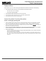
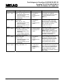
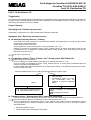
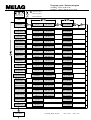
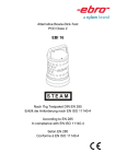
Vacuklav®23-B
Vacuklav®31-B
Program-cycle / Diagnosis-program
Vacuklav®: 24-B / 30-B / 31-B
Euroklav®: 23-S / 23V-S / 29-S / 29V-S
+
+
Press both buttons
hold and...
... switch on power
Diagnosis
Analog-Inputs
S
P
Button choose program: „Enter / Quit / Input“ in the diagnosis-program
S
Button Start/Stop: „Escape / Leave / Interrupt“ in the diagnosis-program
Diagnosis
Digital-Inputs
S
P
P
Buttons: „Continue“ in the Menu in the diagnosis-program
Diagnosis
Digital-Outputs
I1: Door contact
closed
O1: Steam-generator
x.x bar xx°C (off)
Temp_Chambr_Dis
1
I2: OH protector SG
closed
O2: Pre-heating
x.x bar xx°C (off)
I3:
Cooling water
closed
Pressure_Chamber
xxxx mbar
I4: Aqua dem, current
open
Temp_Preht_Cham.
xx.x °C
I5: Door locking dev.
open
Reserve
defective
I6: Aqua dem swimmer
open
Conductivity
xxx µS/cm
I7:
+
Reserve
open
+
Main- und Undermenues can be changed:
+ forward and with - backwards
scrolling and S always leaving the loop.
O3: Vacuum-pump
x.x bar xx°C (off)
O4:
P
(on)
P
O7: SV Press. rel.1
x.x bar xx°C (off)
O8: SV Ventilation
x.x bar xx°C (off)
O9: SV Cool-water
x.x bar xx°C (off)
O10: Door lock
x.x bar xx°C (off)
+
+
P
(on)
O5: Pump/SV aqua dem
x.x bar xx°C (off)
(on)
O6: SV Vacuum
x.x bar xx°C (off)
Keyboard
Nr.: 10
(on)
Keyboard
Nr.: 20
P
Keyboard
Nr.: 40
S
Keyboard
Nr.: 80
P
P
P
Self-Test
Signal
MELAG-GmbH
Gerätename xxx
Self-Test
Memory-Test OK
Self-Test
Battery OK
Printer is
not ready
P
(on)
P
(on)
P
Symbol
xxxxklav XX-X
typ
progvers
spr
parvers
S
Meaning
example
Vacuklav 30-B
Name
V30
Type
3.16
Programversion
D
Language
Parameterversion 01.13
Vacuklav 30-B
V30-3.16 D01.13
Maintenance-data
Update?
P
Service: dd.mm.yy
run cycles: 0
S
Diagnosis
Malfunction-mem
P
Malfunction-mem
print?
Diagnosis
Memory init.
P
Memory init.
Sure?
Diagnosis
Backup Parameter
P
Backup Parameter
Sure?
Diagnosis
Delete Backup
P
Diagnosis
Version
P
S
+
Delete Backup
Sure?
xxxxklav XX-X
typ-progvers spr parvers
hh:mm:ss
x.xx bar xx°C
Neutral position
File: Diagnosis Program.doc
Rev: 0-00/104
Seite 1 von 1
P
Service: dd.mm.yy
run cycles: xx
Diagnosis
Maintenance-data
+
(on)
(on)
Total: xxxx
succesfull.: xxxx
Neutral position
P
P
P
S
Pressure init.
0,x bar 8‘
P
Diagnosis
Statistics
P
Leak-Test
0,3 bar 8‘
+
(on)
Diagnosis
Leakage-search
P
Keyboard
Nr.: 0
(on)
Reserve
(off)
Diagnosis
Self-Test
P
P
S
Temp_Chambr_elec
xx.x °C
Temp_Chambr_Dis
2
Diagnosis
Keyboard
P
S
P
S
+
P
+
P
S
S
P
Fault diagnosis for Vacuklav®31-B
Fault 1: Vacuum system
CONFIGURATION OFCOMPONENT GROUPS IN THE AUTOCLAVE
ERROR 1 VACUUM UNIT
The actual piping plan is contained in Drawing No. 31B-010.
VACUKLAV 31-B Configuration of the component
groups in the autoclave (TOP VIEW)
FRONT
This overview shows a rough schematic of the spatial configuration of the component groups, pipes, and hoses, in the Vacuklav® 31-B. The following error descriptions will refer to this overview to help you find the component groups to be checked.
SQ1
VV1
K
VQ
VDA1
PV
Item
Bezeichnung
Description
VDA2
F
F
PQ
K
VV2
VB
H1
SLW
C
C
F
H1
K
PQ
PV
S LW
S Q1
V
V
V
B
VB
B
V DA1
V DA2
V
V
Q
VQ
Q
V
V
V
VV
V111
V
V
V
VV
V222
Kühler
Filter
Dampferzeuger
Kessel
Pumpe aqua dest
Vakuumpumpe
Sensor Leitwert
Strömungswächter
Ventil (Magnet~)
Belüftung
Druckablaß 1
Druckablaß 2
Speisewasser aqua dest
Vakuum 1
Vakuum 2
cooler
filter
steam generator
vessel
pump for distilled water
vacuum pump
sensor for conductivity
flow sensor for dist. water
valve (solenoid)
ventilation
pressure release 1
pressure release 2
feed water (distilled)
vacuum 1
vacuum 2
State of valve
when no current is applied
(dead)
ACOUT
(power
output)
4
1
5
3
open
closed
closed
closed
closed
closed
8
7
9
5
6
6
F
Seite 1 von 5
Rev.-Nr.:98/0
FAULT_01 for 31B.doc
Fault diagnosis for Vacuklav®31-B
Fault 1: Vacuum system
Tripping conditions:
Fault conditions may occur if the monitoring time Uet1 was exceeded for achievement of the following:
•
The required evacuation pressures for the individual sub-atmospheric pulses
–
P37, P38, P40, P41 for cold starts
–
P1, P2, P21, P22 for hot starts
•
The required evacuation pressure (P17) for the vacuum test
•
The required evacuation pressure (P12) for evacuation / pressure relief
•
The required minimum pressure for drying (P3).
Causes of the problem / Correction of the problem
Action / checking by operating staff:
•
Check for defects and for soiling of the door seal and the sealing surfaces of the sterilization chamber,
and on the round plate around the door of the sterilization chamber. Repair and clean if necessary.
•
Check to make sure that the autoclave is properly set up (it must be installed with a tilt (at slope), as
described in the operating instructions).
•
Check to make sure that the condensate drain at the bottom of the sterilization chamber is not stopped.
It can be stopped if instruments, filter paper, etc. fall onto the bottom of the chamber.
•
Check for the following:
–
If you are using the internal system for supply of demineralised water, check to make sure that the
pressure-release pipe is not stopped.
–
If you are using an external waste-water connection that empties into the building waste-water system, check to make sure that this drain pipe does not have a kink (make sure the water can flow
freely out).
Seite 2 von 5
Rev.-Nr.:98/0
FAULT_01 for 31B.doc
Fehlerdiagnose Vacuklav®31-B
Fehler 1: Vakuumanlage
Faults in the autoclave / Correction of faults by technical service personnel
Fault 1
Vacuum system
Start the vacuum test
Is the vacuum pump
running?
Note:
No
Æ Fault Class: Control fault / faulty pump Please check the following for faults: power
output ACOUT3; fuse F1; possibly defective vacuum pump. Correct the fault, and then go
to next.
Yes
Vacuum test OK?
(Leak rate < 1.3 mbar/min)
Important: All vacuum tests must be conducted with a cold, dry autoclave. Watch the
evacuation pressure achieved here, and the pressure change over time (from the display).
No
Yes
Leak rate is too great
(> 1.3 mbar) and permanent
pressure rise
Vacuum test OK
Leak rate OK
Pressure is stable
Special vacuum test OK?
(System flag F11 = 1)
(Pressure stable?)
No
Æ Fault Class: Leak fault
Repair the leak in the intake
line; then next
"Fault 31: System leaks"
Pressure rise over P3
(very large leaks)
"Fault 1: Vacuum
system"
Æ Fault Class: Leak fault
Stop the leaks and then next
The sub-atmospheric
pressure achieved is very
weak, or the pressure is
the same as in the room.
Yes
Æ Fault Class: Vacuum fault
Pump system too weak
Correct fault and go on with
normal program start.
Sub-atmospheric pressure is within the range
of moderate to just less
than the evacuation
pressure (P17).
In the Service Program, raise the evacuation pressure (P17) for the vacuum test by approx. 20 mbar more than
the evacuation pressure reached during the first test. Then repeat the test. (Important: When changing
P17, make sure that P13 is always greater than P17. If necessary, also raise 13 to ensure that P13 >
P17. If this is not done, you will receive the error message “System leak”.)
Seite 3 von 5
Rev.-Nr.:98/0
FAULT_01 for 31B.doc
Fault diagnosis for Vacuklav®31-B
Fault 1: Vacuum system
Fault 1: Vacuum system
Æ Fault class: Fault in control system or function of the pump
You can check the input voltage for the vacuum pump, as well as the function of the pump, as follows:
Make sure that the intake side is vented, since the pump will not start against a vacuum. In the Diagnosis
program, switch on the solenoid valves for vacuum 1 + 2 (VV1 + VV2) by switching on the power output
ACOUT 6 (the valves are open when the current is applied).
In the Diagnosis Program, switch on the pump
(PV) by switching the power output ACOUT 3.
Does the pump now run?
No
Yes
Check Fuse F1. Is it OK?
fuse F1.
Yes
Test the power output
EP2-2 on the circuit board
with a meter. Output OK?
Proceed to the next step in the higher-level
fault-analysis plan.
No Exchange
No Exchange the
circuit board.
Yes
The pump is defective.
Exchange the pump.
Æ Fault class: the vacuum performance of the pump system is too weak
► The vacuum solenoid valves 1 + 2 do not open (VV1, VV2)
•
•
The solenoid valve, or coil, or rectifier plug are defective.
The activation for the solenoid valve (output 6) is defective.
Switch on output 6 in the Diagnosis program.
Check the electric control system and the switching behavior of the solenoid valve.
► The flow resistance in the intake line is too high
•
Filter in the intake fitting on the sterilization
chamber is clogged up
► The pressure-sensor signal is defective, or the
processing of this signal is not correct
•
The level of the pressure-sensor signal, or the signal processing,
is too high. See the section “Sensor Fault Group”.
► The suction of the vacuum pump is too weak
Check the vacuum performance of the membrane as follows:
1. Check to see if there are leaks.
2. Make sure that the chamber to be evacuated is empty and dry.
3. If there are no leaks, and if the chamber is empty and dry,
check the performance of the pump. It must be at least
800 mbar in 80 s, or 900 mbar in 180 s.
4. If there are no leaks, and if the chamber is empty and dry, and if the performance of the pump does not meet
the above level (800 mbar in 80 s, or 900 mbar in 180 s), then exchange the pump.
Seite 4 von 5
Rev.-Nr.:98/0
FAULT_01 for 31B.doc
Fault diagnosis for Vacuklav®31-B
Fault 1: Vacuum system
Fault 1: Vacuum system
Fault class: leakages
Leaks in the solenoid valves
► The solenoid valve for the venting (VB) will not close, or it leaks
• Check the coil, the rectifier plug, and the control at output 8
• Solenoid valve dirty. Check the plunger / is the seating tight?
Test under sub-atmospheric conditions (Vacuum Test program)
Remove the sterile filter. Cover the opening of the sterile-filter fitting
with the palm of your hand. Then observe the pressure reading.
► The solenoid valve for pressure release 1 + 2 (VDA1, VDA2) has a leak
• Solenoid valve dirty. Check the plunger / is the seating tight?
Test under sub-atmospheric conditions (Vacuum Test program)
Observe the water column in the hose between the solenoid valve “Pressure release” and the sterile filter.
If there is a leak, water will be pulled in the direction of the solenoid valve.
Loosen the hose on the T-fitting for the cooling-water drain, close with finger, observe the pressure reading.
► The solenoid valve for the vacuum 1 + 2 (VV1 + VV2) has a leak (Vacuum Test program)
• Solenoid valve dirty. Check the plunger / is the seating tight?
Test under sub-atmospheric conditions (Vacuum Test program):
Observe the water column in the hose between the intake fitting for the chamber and the solenoid valve for the
vacuum. If there is a leak, water will be pulled in the direction of the solenoid valve.
► The solenoid valve for the feed pump (VQ) has a leak
• Solenoid valve dirty. Check the plunger / is the seating tight?
Test under sub-atmospheric conditions (Vacuum Test program):
Observe the water column in the intake hose leading to the input
of feed water between the conductivity-sensor and the intake fittings
of the pump, and on the pressure side of the pump. If there is a leak,
water will be pulled in the direction of the solenoid valve.
Leaks at the threaded connections and adhesive bonding
Test under sub-atmospheric conditions: start the “Leak search” procedure in the Diagnosis Program (0.3 bar, for
8 min). Or, feed compressed air into the autoclave through the vent-filter fittings (in Diagnosis program, close output 8, “MV vent”). Brush a soapy solution on the points shown below and check to see if there are any air bubbles.
Adhesive-bonded threaded hose
connections at the chamber
Threaded connections
for temperature sensor
Cutting-ring threaded
connection for steam
generator / chamber
Cover seal for
steam generator
Swivelled threaded
connection for the
steam generator
Plug of the pressure-release
filter
Seite 5 von 5
Rev.-Nr.:98/0
Adhesive bond for the T-fitting in
the pressure-release filter
FAULT_01 for 31B.doc
Fault diagnosis Vacuklav®24-B/24V/30-B/31-B
Fault 2: Steam generator
FAULT 2: Steam generator
Triggered by :
The following monitoring time limits have been exceeded
• Uet2 for the warming-up phases in the fractionations until reaching P5 (warm start), P39 (cold start),
P43 (cold start disinfection) or
• Uet3 for the heating up to the sterilization / disinfection temperature T1-T5
Causes / Remedy
Operating fault / Checks by personnel:
•
•
Maximum load exceeded
Mains power voltage too low (check mains installation)
Appliance fault / Repair by technical service personnel
► Control steam generator Output ACOUT1 faulty
check in "Diagnosis Program":
Switch on ACOUT1, (the LED for this output lights up),
Measure voltage at output ACOUT1
► Capillary control "2nd Overheating protection for the
Steam Generator" is faulty
• Control unit is permanently open
Check for passage when cold
• Control unit switches too soon
During a program, measure the voltage behind the control unit
with a sufficient water level in the steam generator (check level in the
condensate return) the control unit must not switch
► "3rd Overheating protection for the Steam Generator"
fuse blown on the heating coil of the steam generator
(contact broken )
Measure voltage behind fuse, this will usually be due to a fault at the
output ACOUT1 of the control unit and additionally failure of the 2nd
overheating protection
► Heating Steam Generator faulty
In the Diagnosis Program switch on output ACOUT1, measure voltage
directly at the connectors of the heating coil of the steam generator
(voltage measured but coil remains cold)
► Capillary level control unit faulty
• Control unit does not open on overheating (water shortage).
Water shortage is not recognised and the overheating protection
switch switches off.
Functional test of the capillary level control unit:
In the "Service Program“/ "switch-times" set z24 = 0,
Start Universal Program with full load, by switching capillary control unit
and the resultant feed of distilled/demineralized feed water should
compensate for the water shortage in the steam generator
(observe condensation return to steam generator)
► Pressure sensor-Signal/ Signal processing faulty
• Pressure sensor signal or the signal processing too low
Steam generator heats until security-valve opens)
Page 1 of 1
Rev.-Nr.:00/0
FAULT_02 for 31B.doc
Fault Diagnosis Vacuklav®24-B/24V/30-B/31-B
Fault 6: Ventilation
FAULT 6: Ventilation
Triggered by: The monitoring time limit Uet7 for the ventilation of the chamber until reaching pressure P12 was
exceeded
Causes/ Remedy
Operating fault/Check by personnel:
•
The sterile filter is dirty, this will the autoclave show with the display “Replace sterile filter”
• As a check, remove the filter and carry out a sterilization cycle with no load. Exchange sterile filter
Appliance fault / Repair by technical service personnel
► Ventilation solenoid valve does not open
• Solenoid valve blocked mechanically (soiling)
Open valve casing, clean or exchange valve
• Control for ventilation solenoid valve faulty, output ACOUT8 giving
permanent signal (relay stuck)
Exchange CPU-board
► Pressure sensor/ Analog input AIN 3 measures too low
• Pressure sensor signal/ Signal processing to control too low, Pressure signal after ventilation still < P12,
follow up fault would normally be “Fault 35: Sterilization TO”
Check that the pressure displayed in “Diagnosis-Program“/ “Analog input“ is plausible, displayed value
should be current air pressure (door open)
See also under “Fault 35 Sterilization TO“ – “Pressure sensor, analog input AIN 3 measures too low“
Exchange pressure sensor
If a fault is still reported: Exchange CPU-board
► Parameter P12 wrong
In “Service Program“ check that the parameter setting P12 = 800 is correct, if necessary update setting
(particularly for Vacuklav 24 and for installation at high altitudes).
Page 1 von 1
Rev.-Nr.:00/0
FAULT_06 for 31B.doc
Fault Diagnosis Vacuklav®24-B/30-B/31-B
Euroklav®23-S/23V-S/29-S/29V-S
Fault 9: Door open
FAULT 9: DOOR OPEN
Triggered by: Door contact (digital input DIN1) was closed during a program
Causes/ Remedy
Operating fault/ Checks by personnel:
•
Press down door handle as far as possible
Appliance fault / Repair by technical service personnel
► Door switch faulty
•
•
•
Door switch faulty / needs readjustment
Electrical connection to CPU-board interrupted
Digital input DIN1 on CPU-board faulty
Check in the MELAG- Diagnosis-Program, "Digital Inputs: E 1“
it the door switch needs adjusting, see below.
Adjusting the door contact switch
•
•
•
•
•
•
In the diagnosis program "Digital Inputs“ select
"Input E1: Door contact“
Insert 8 mm spacer (M8 bolt or similar) between
lock housing and upper door beam as shown
Close door and push down door lock until contact is made
Loosen right fixing screw of door contact switch
Turn door contact switch around the left fixing
screw until door contact switch engages (Display
shows "closed", switching sound)
Tighten right adjusting screw in new position
Page 1 of 1
Rev.-No. :00/0
FAULT_09 for 31B.doc
Fault Diagnosis Vacuklav®24-B/30-B/31-B
Euroklav®23-S/23V-S/29-S/29V-S
Fault 12: Door locking
FAULT 12 : Door locking
Triggered by:
•
The door locking contact DIN5 is not switched after time period z31 (Door closed when no power supply,
contact DIN5 still open).
Causes / Remedy:
Operating fault / Check by operating personnel :
•
Locking bolt sticking or out of alignment
Appliance fault / repair by technical service personnel:
• Control for door locking output ACOUT 10
on CPU-board is faulty (permanent voltage)
• Contact switch on door lock is faulty
• Locking bolt cannot move freely / is blocked
ca.2mm
Adjusting the door lock
•
Dismantle door cladding, close door
•
Loosen fixing screws on the door lock
•
By shifting the door lock centralise the face of the
locking bolt in the depression as shown, with a
spacing of approx. 2 mm
•
Tighten fixing screws on the door lock
Door lock will not disengage
The Display permanently shows "Please wait - Door unlocking" after switching power on or after a program has
ended (no explicit malfunction reported ):
• Control "Door locking" Output ACOUT 10 on CPU-board is faulty
• Drive for the door locking is faulty
• Door contact switch of the door lock is faulty
• Locking bolt cannot move freely / is blocked
In the MELAG Diagnosis Program switch on output ACOUT10, functional control power output and locking
Unlock door manually (for example with the help of a screwdriver).
Page 1 of 1
Rev.-Nr.:00/0
FAULT_12 for 31B.doc
Fault-diagnosis Vacuklav®24-B/24V/30-B/31-B
Euroklav®23-S/23V-S/29-S/29V-S
Fault 18: Sensor "nr" Input "nr"
FAULT18 : Sensor "nr" Input "nr"
Triggered by:
•
The internal check of the sensors for temperature, pressure, or conductivity showed too large deviations. Such
malfunction reports can occur immediately when the appliance is switched on or while a program is running.
Causes / Remedy
Operating fault / Checks by personnel:
For "Fault 18 Sensor: 6 Input 6" (conductivity sensor is faulty), check first that if demineralized or distilled water is
supplied from a container that this has not accidentally been filled with something else.
Appliance fault/ Repair by technical service personnel
Overview of sensors / analog inputs
Sensor
No.
Input
No.
SensorSensor designation/
characteristic -function
1
AIN1
PT 1000
Class A
2
AIN2
PT 1000
Class A
3
AIN3
4
AIN4
Pressure
sensor
0 - 10V at
0 - 4000mbar
PT 1000
Class A
6
AIN6
Water
conductivity
sensor
"Temp_chambr_elec“
Temperature sensor
"Steam" for program
control
"Temp_Chambr_Dis1/2“
Temperature sensor
"Steam" for
display/record and
monitoring
"Pressure chamber“
Pressure sensor for
program control Display,
record and monitoring
"Temp_preht_chamb“
Temperature sensor for
control of chamber
temperature
"Conductivity“ display/
monitoring elec.
conductivity
Signal +
Signal -
Ub+ =24V
Pressure sensor AIN 3
Temperature sensor preheating, AIN4
Conductivity sensor, AIN6
Temperature sensors Steam AIN1/AIN2
Seite 1 von 2
Rev.-No.:00/0
FAULT_18 for 31B.doc
Fault-diagnosis Vacuklav®24-B/24V/30-B/31-B
Euroklav®23-S/23V-S/29-S/29V-S
Fault 18: Sensor "nr" Input "nr"
Display message
Triggered by/Cause
Fault18
Temperature at analog input
Sensor: 1 Input 1
AIN1 ≤ 0°C or ≥ T23
• Temperature sensor faulty
Short-circuit/Open
• Signal processing on CPUboard faulty
Fault18
Temperature measured at
analog input
Sensor: 2 Input 2
AIN2 ≤ 0°C or ≥ T23
• Temperature sensor faulty
Short-circuit/Open
• Signal processing on CPUboard faulty
Fault18
Pressure measured to analog
Sensor: 3 Input 3
input AIN3 ≤ 0 mbar or ≥ P19
• Pressure sensor faulty
• Signal processing to CPUboard faulty
• + 24V (voltage to pressure
sensor) at CPU-board faulty
Fault18
Temperature measured at
Sensor: 4 Input 4
analog input AIN4
≤ 0°C or ≥ T23
• Temperature sensor faulty
Short-circuit/Open
• Signal processing on CPUboard faulty
Fault18
Conductivity measured at
Sensor: 6 Input 6
analog input AIN6 ≥ L3
Page 2 of 2
Correction
• Exchange
temperature
sensor
• Exchange CPUboard
Comments / Remarks
Until the sensor/CPU-board can be
exchanged, in the MELAG
Service-program set FLAG F28 to
1, AIN 2 then takes over the
AIN
1 of
function
• Exchange
temperature
sensor
• Exchange CPUboard
Until the exchange of the
sensor/CPU-board, unplug the
defective sensor on input AIN2,
move the sensor on AIN1 to AIN2
and in the MELAG-ServiceProgram set F28 to 1
• Exchange
pressure sensor
• Exchange CPUboard
Sequence of testing:
+24V supply (between GND and
+UB) measured at pressure
Signal voltage at pressure sensor
sensor
between GND and + Signal must
be around 2.5V (corresponds
1000mbar air pressure)
• Exchange
temperature
sensor
• Exchange CPUboard
Until exchange of the sensor/CPUboard, in the MELAG- Service
program set FLAG F5 to 0, this
deactivates the entire preheating
including malfunction reports drying quality will be reduced
• Check for shortcircuits of the
conductivity
Exchange CPU• sensor
board
Until exchange of the CPU-board,
in the MELAG-Service program set
FLAG F3 to 0, this deactivates the
entire conductivity measurement
including malfunction reports temporarily no automatic checks of
water quality ,
Rev.-No.:00/0
FAULT_18 for 31B.doc
Fault diagnosis Vacuklav®24-B/24V/30-B/31-B
Euroklav®23-S/23V-S/29-S/29V-S
Fault 21: Preheating
FAULT 21 Preheating
Triggered by :
The monitoring time limit Uet11-Uet16 from switching on the preheating until reaching the necessary temperature
has been exceeded
Causes/ Remedy
Operating fault/Checks by personnel :
•
•
Mains electricity voltage too low: Check mains supply installations
Appliance is cold, door not closed properly during preheating
Appliance fault / Repair by technical service personnel
► Control unit Preheating Output ACOUT2 is faulty
Check in "MELAG Diagnosis-Program":
Switch on output ACOUT 2, (the LED for this output lights up),
Measure voltage at output ACOUT2
► Overheating-protection Preheating faulty
• Control unit permanently open
• Control unit switches too soon, and stops heating power:
Measure voltage behind the control unit during the program
► Preheating faulty
In the "MELAG diagnosis program" switch on output ACOUT2, measure voltage directly at the connection
to the preheating (voltage but heating remains cold), or check current through heating
Until a repair is possible, as a temporary measure set the FLAGS F5=0 to deactivate the preheating and
the associated malfunction report .
Page 1 of 1
Rev.-Nr.:00/0
FAULT_21 for 31B.doc
Fehlerdiagnose Vacuklav®24-B/24V/30-B/31-B
Euroklav®23-S/23V-S/29-S/29V-S
Fehler 22: Overheating preheating
FAULT 22: Overheating of preheating
Triggered by :
The limit value for the preheating-temperature T10 was exceeded
Causes / Remedy
Operating faults / Checks by personnel:
Appliance fault / Repair by technical service personnel
► Control of Pre-heating Output ACOUT2 faulty
At output ACOUT2 there is a permanent voltage (although LED off), i.e. semiconductor relay faulty,
exchange CPU board
► Temperature sensor Pre-heating faulty
Temp.-sensor Preheating measurements too high/fluctuating, in the "MELAG Diagnosis Program" check
the analog input AIN4 during a program by pressing the button " - ".
Exchange temperature sensor
Temp.-sensor "Preheating" AIN4
Under the chamber insulation,
directly on the heating
stuck
► Signal processing at analog input AIN4 faulty
Exchange CPU-board
Until a repair, it is possible to temporarily deactivate the preheating and the malfunction message by
setting the FLAG F5=0, and in addition if the output ACOUT2 is defective, disconnect the contacts to the
pre-heating from the output.
Page 1 of 1
Rev.-Nr.:00/0
FAULT_22 for 31B.doc
Fault Diagnosis Vacuklav®24-B/24V/30-B/31-B
Euroklav®23-S/23V-S/29-S/29V-S
Fault 26: A/D-Converting
FAULT 26: A/D-converter
Triggered by:
The maximum permissible deviation for the signal processing in the CPU (A/D-conversion) was exceeded
Causes/ Remedy
Operating faulty/Checks by operating personnel:
Appliance fault / Repair by technical service personnel
► Hardware signal processing fault
Exchange CPU-board
Page 1 of 1
Rev.-Nr.:00/0
FAULT_26 for 31B.doc
Fault-diagnosis Vacuklav®24-B/24V/30-B/31-B
Euroklav®23-S/23V-S/29-S/29V-S
Fault 29: Battery RAM
FAULT 29: Battery RAM
Triggered by :
In the data memory of the CPU there is a data inconsistency or a loss of data, This can be due to an electrical
disturbance (e.g. very high power supply disturbances), a low battery voltage or a hardware defect in the RAM. On
quitting the fault the clock time is automatically set at 00:00 and the load counter is reset to the value from the
EEPROM. At the same time all record data in the memory is deleted.
Causes / Remedy
Operating fault / Checks by personnel:
• After quitting the malfunction report : Enter correct time and date settings and restart a program.
Appliance fault / Repair by technical service personnel
► Battery voltage too low
•
If fault occurs regularly exchange battery on CPU- board (battery connections soldered)
► Fault in RAM
•
Page 1 of 1
If after exchanging the battery there is still a malfunction report, then there is a permanent fault in the
RAM - replace the CPU board
Rev.-Nr.:00/0
FAULT_29 for 31B.doc
Fault Diagnosis Vacuklav®24-B/24V/30-B/31-B
Fault 34: Sterilization TU
FAULT 34: Sterilization TU
Triggered by:
Temperature fell below the minimum level for the sterilization/disinfection during the period T1-T5 (measured at the
temperature sensor "Temp_chambr_elec“ at AIN1).
Cause / Remedy
Operating fault / Checks by personnel:
•
Load exceeds maximum level allowed
Appliance fault / Repair by technical service
► No saturated steam pressure / Leaking
As a result of too much residual air in the autoclave chamber, the temperature is not high enough to allow
the generation of saturated steam.
Check using the print-out records:
Control pressure in record corresponds to control pressures P 6 – P10
Reading in record from temperature sensor "Temp_Chamber_Dis1/2" at Analog input AIN2 is also too low
(corresponds to the temperature of temperature sensor "Temp_chambr_elec" at analog input AIN1 (see
last line of record print-out.)
Carry out a vacuum test - if there is no leaking see under "Pressure sensor signal too high"
► Temperature sensor "Temp_Kess_Prog"/ Analog input AIN1 measures too low
Check using the record print-out:
Print-out reading for control pressure corresponds to control pressures P 6 – P10
Print-out reading for temperature sensor "Temp_Chamber_Dis1/2“ at analog input corresponds with the
pressure required for saturated steam.
In order to determine whether the fault lies in the temperature sensor or the signal processing on the CPUboard, proceed as follows:
Switch temperature sensors AIN1 and AIN2 and start the program again,
•
•
Program
runs
without
disturbance, (or with "Fault 27“ )
Temperature on print-out too low
to produce saturated steam ?
Exchange
temperature
sensor
now
on
AIN2
(previously on AIN 1)
Page 1 of 3
Rev.-Nr.:00/0
•
•
Fault 34 again
Does temperature reading on
print-out correspond with the
pressure to produce saturated
steam?
Signal processing on CPUboard faulty,
Exchange CPU-board
FAULT_34 for 31B.doc
Fault Diagnosis Vacuklav®24-B/24V/30-B/31-B
Fault 34: Sterilization TU
► Pressure sensor / Analog input AIN 3 measures too high
If the checks show there is no leak (Vacuum test), check through the following on the program print-out:
Pressure reading on print-out corresponds to the control pressures P 6 – P10
Print-out readings from temperature sensor "Temp_chambr_elec“ (AIN1) and from temperature sensor
"Temp_Chamber_Dis1/2“ (AIN2) correspond to one another, but both are too low to produce saturated
stream.
• Exchange pressure sensor
• If there is still a fault, exchange the CPU-board
► "Overheating protection - Steam generator" engages
•
•
Capillary tube level control (digital input DIN 2) is faulty
Control does not open on overheating (shortage of water), water shortage is therefore not recognised and
the capillary tube overheating control switches off.
(see also "Fault 2 Steam generator“)
Observe level regulation in the condensation return pipe, exchange steam generator
Capillary tube overheating control is faulty.
Control switches too soon, exchange steam generator
Observe level regulation in the condensation return pipe, exchange steam generator
► "Poor control response of steam generator"
Poor heat transmission from the heating coil of the steam generator, particularly temperature fluctuations on
transition from warming-up phase to sterilization phase can take the temperature below the sterilization
temperature for brief periods
Exchange steam generator
Page 2 of 3
Rev.-Nr.:00/0
FAULT_34 for 31B.doc
Fault Diagnosis Vacuklav®24-B/24V/30-B/31-B
Fault 34: Sterilization TU
Fault diagnosis using the program print-out
FAULT 34: Sterilization TU
The control pressure reading on the printout at the time of the fault corresponds to
the rated values P6 – P10
The control pressure reading on the print-out
at the time of the fault is lower than the rated
values P6 – P10
The overheating protection of the steam
generator switches off
• The capillary tube level regulator DIN 2
does not switch / switches too late (water
shortage not recognised)
• The
capillary
control
"Overheating
protection" switches too soon.
Exchange steam generator
The temperature of temperature sensor
"Temp_Chambr_Dis1/2“ (Analog input
AIN2) corresponds to that of
temperature sensor
"Temp_chambr_elec“ (analog input
AIN1), but both temperatures are well
below the theoretical value needed for
saturated steam.
Leaking, no saturated
steam (do vacuum test)
The temperature of temperature sensor
"Temp_Chambr_Dis1/2“ (analog input
AIN2) corresponds to the
theoretical
saturated steam pressure, i.e. only the
temperature from the temperature sensor
"Temp_chambr_elec“ (analog input AIN1)
lies below the theoretical value needed for
saturated steam.
Pressure sensor signal faulty, too
high
• Pressure sensor faulty
• Signal processing on CPUboard faulty
Exchange pressure sensor /
CPU-board
•
•
Program
runs
without
disturbances,
(possibly "Fault 27") ?
Temperature on print-out too low
for saturated steam ?
Exchange
temperature
sensor now on AIN2 (was
previously on AIN 1)
Page 3 of 3
Temperature signal from analog input
AIN 1 faulty
Change temperature sensors on AIN1
and AIN2 and restart program
Rev.-Nr.:00/0
•
•
Fault 34 again?
Does temperature on printout
correspond
with
pressure
to
generate
saturated steam?
Signal processing on CPUboard faulty,
Exchange CPU-board
FAULT_34 for 31B.doc
Fault-diagnosis Vacuklav®24-B/24V/30-B/31-B
Fault 35: Sterilization TO
FAULT 35: Sterilization TO
Triggered by :
The maximum temperature (T1-T5)+D5 for the sterilization / disinfection during the period T1-T5 (measured by the
temperature sensor "Temp_chambr_elec“ at AIN1) has been exceeded
Cause / Remedy
Operating fault / Checks by personnel:
Appliance fault / Repair by technical service
► Temperature sensor "Temp_Kess_Prog"/ Analog input AIN1 measures too high
Check using the record print-out:
Print-out reading for control pressure corresponds to control pressures P 6 – P10
Print-out reading for temperature sensor "Temp_Chambr_Dis1/2“ at analog input corresponds with the
pressure required for saturated steam.
In order to determine whether the fault lies in the temperature sensor or the signal processing on the CPUboard, proceed as follows:
Switch temperature sensors AIN1 and AIN2 and start the program again,
•
•
Program
runs
without
disturbance, (or with "Fault 27“ )
Temperature on print-out too high
to produce saturated steam ?
Exchange temperature sensor now
on AIN2 (previously on AIN 1)
• Fault 35 again
Does temperature reading on printout correspond with the pressure to
produce saturated steam?
Signal processing on CPUboard faulty,
Exchange CPU-board
► Pressure sensor / Analog input AIN 3 measures too low
Check using the program print-out records:
Pressure reading on print-out corresponds to the control pressures P 6 – P10
Print-out readings from temperature sensor "Temp_chambr_elec“ (AIN1) and from temperature sensor
"Temp_Chambr_Dis1/2“ (AIN2) correspond to one another, but both are too high to produce saturated
stream
• Exchange pressure sensor
• If there is still a fault, exchange the CPU-board
► Control for steam generator output ACOUT1 faulty
Check using the program print-out records / test voltage at output ACOUT1:
In comparison with the control pressures P 6 – P10 pressure reading on print-out are too high
Pressure reading on print-out corresponds to the control pressures P 6 – P10
Print-out readings from temperature sensor "Temp_chambr_elec“ (AIN1) and from temperature sensor
"Temp_Chambr_Dis1/2“ (AIN2) correspond to one another, but both are too high to produce saturated
stream
Voltage at ACOUT1 does not switch off during the control process:
• Check heat transition semi-conductor relay ACOUT1 to cooling body
• Exchange the CPU board
Page 1 of 2
Rev.-Nr.:00/0
FAULT_35 for 31B.doc
Fault-diagnosis Vacuklav®24-B/24V/30-B/31-B
Fault 35: Sterilization TO
Fault diagnosis using the program print-out
FAULT 35 Sterilization TO
The control pressure reading on the printout at the time of the fault corresponds to
the rated values P6 – P10
The control pressure reading on the print-out
at the time of the fault is markedly higher than
the rated values P6 – P10
Signal to the steam generator Output
ACOUT1 is faulty / does not switch off
• Check
heat
transfer
semiconductor relay ACOUT1 to
cooling body
• Exchange CPU-board
The temperature of temperature sensor
"Temp_Chambr_Dis1/2“ (Analog input
AIN2) corresponds to that of
temperature sensor
"Temp_chambr_elec“ (analog input
AIN1), but both temperatures are well
above the theoretical value needed for
saturated steam.
The temperature of temperature sensor
"Temp_Chambr_Dis1/2“ (analog input AIN2)
corresponds to the theoretical saturated
steam pressure, i.e. only the temperature
from
the
temperature
sensor
"Temp_chambr_elec“ (analog input AIN1)
lies above the theoretical value needed for
saturated steam.
Pressure sensor signal faulty, too low
• Pressure sensor faulty
• Signal processing on CPU-board
faulty
Exchange pressure sensor/ CPUboard
Temperature signal from analog input AIN 1
faulty
Switch temperature sensors AIN1 and AIN2
and restart program
•
•
Program runs without
disturbances,
(possibly "Fault 27") ?
Temperature on print-out too
high for saturated steam ?
Exchange temperature sensor
now on AIN2 (was previously on
AIN 1)
Page 2 of 2
Rev.-Nr.:00/0
•
•
Fault 35 again?
Does temperature on print-out
correspond with pressure to
generate saturated steam?
Signal processing on CPUboard faulty,
Exchange CPU-board
FAULT_35 for 31B.doc
Fault-diagnosis Vacuklav®24-B/24V/30-B/31-B
Fault 37: Sterilization PO
FAULT 37: Sterilization PO
Triggered by:
The measured pressure gives a calculated value for the temperature required for saturated steam that lies above
the maximum temperature (T1-T5)+D5 for the sterilization / disinfection during the period T1-T5
Causes / Remedy
Operating fault / Checks by personnel:
Appliance faults / Repair by technical service personnel
► Control of Steam Generator Output ACOUT1 faulty
Check the control on the basis of the program print-out records/ Check voltage at output ACOUT1:
Print-out pressure readings too high in comparison with pressures P 6 – P10
Print-out reading for temperature sensor "Temp_Kess_Prog“ (AIN1) and for temperature sensor
"Temp_Chambr_Dis1/2“ (AIN2) correspond to one another, but both are too high for the generation of
saturated steam
Voltage at ACOUT1 does not switch off during the regulation :
• Check thermal transition semiconductor relay ACOUT1 to the cooling body
• Exchange CPU-board
► Pressure sensor signal fluctuates
Check using the record print-out:
Pressure values show fluctuations, peaks above the relevant pressures P 6 – P10
Recorded temperatures from temperature sensor "Temp_chambr_elec" (AIN1) and from temperature
sensor "Temp_Chambr_Dis1/2“ (AIN2) correspond to one another
•
•
Exchange pressure sensor
If there are further malfunction reports exchange CPU-board
► "Poor regulatory behaviour of steam generator"
Poor heat transition from the heating coil of the steam generator, particularly in the transition from the heating
up phase to the sterilization phase it is possible that the temperature will exceed the theoretical sterilization
temperature for short periods
Lower P6-P10 and increase D5
Exchange steam generator
Page 1 of 1
Rev.-Nr.:00/0
FAULT_37 for 31B.doc
Fault-diagnosis Vacuklav®24-B/24V/30-B/31-B
Euroklav®23-S/23V-S/29-S/29V-S
Fault 38: Sterilization TD
FAULT 38: Sterilisation TD
Triggered by:
The maximum permissible difference D6 between the temperature value to generate saturated steam calculated on
the basis of the measured pressure and the value measured by the temperature sensor "Temp_chambr_elec“ at
AIN1 during the period T1-T5 was exceeded.
Cause / Remedy
Operating fault / Checks by personnel:
Overheating, in particular in the case of textile loads soiled with chemicals
Appliance fault / Repair by technical service
► No saturated steam pressure / Leaking
As a result of too much residual air in the autoclave chamber, the temperature is not high enough to allow
the generation of saturated steam.
Check using the print-out records:
Control pressure in record corresponds to control pressures P 6 – P10
Reading in record from temperature sensor "Temp_Chambr_Dis1/2" at Analog input AIN2 is also too low
(corresponds to the temperature of temperature sensor "Temp_chambr_elec" at analog input AIN1 (see
last line of record print-out.)
Carry out a vacuum test
► Temperature sensor "Temp_Chambr_elec"/ Analog input AIN1 fehlerhaft
Check using the record print-out:
Print-out reading for control pressure corresponds to control pressures P 6 – P10
Print-out reading for temperature sensor "Temp_Chambr_Dis1/2“ at analog input corresponds with the
pressure required for saturated steam.
In order to determine whether the fault lies in the temperature sensor or the signal processing on the CPUboard, proceed as follows:
Change temperature sensors on AIN1 and AIN2 and start the program again
•
•
Program
runs
without
disturbance, (or with "Fault 27“ )
Temperature
on
print-out
deviates from that needed to
produce saturated steam ?
Exchange temperature sensor
now on AIN2 (was on AIN 1)
•
•
Fault 38 again
Temperature reading on printout
corresponds
with
the
pressure to produce saturated
steam
Signal processing on CPU-board
faulty,
Exchange CPU-board
► Pressure sensor / Analog input AIN 3 measures incorrectly
If the checks show there is no leak (Vacuum test), check through the following on the program print-out::
Pressure reading on print-out corresponds to the control pressures P 6 – P10
Print-out readings from temperature sensor "Temp_Chambr_elec“ (AIN1) and from temperature sensor
"Temp_Chambr_Dis1/2“ (AIN2) correspond to one another, but both are too low or too high to produce
saturated stream
• Exchange pressure sensor
• If there is still a fault, exchange the CPU board
Seite 1 von 1
Rev.-Nr.:00/0
FAULT_38 for 31B.doc
Program-cycle / Service-program
Vacuklav®: 24-B / 30-B / 31-B
Euroklav®: 23V-S / 29V-S / 23-S / 29-S
+ + + P
Press all three
buttons and hold.
+
selection buttons
P
button "Program"
S
button Start-Stop
...and switch on
power
+
Pressures
P1: xx
Pressures
P2...Pn: xx
MELAG-Service
Temperatures
Temperatures
T1: xx
Temperatures
T2...Tn: xx
Temperatures
Tn: xx (flashs)
MELAG-Service
Temp.-Diff.
Temp.-Diff.
D1: xx
Temp.-Diff.
D2...Dn: xx
Temp.-Diff.
Dn: xx (flashs)
MELAG-Service
process-times
process-times
t1: xx
process-times
t2...tn: xx
process-times
tn: xx (flashs)
MELAG-Service
times * 50 ms
times * 50 ms
tms1: xx
times * 50 ms
tms2...tmsn: xx
times * 50 ms
tmsn: xx (flashs)
MELAG-Service
Switch.-times
Switch.-times
z1: xx
Switch.-times
z2...zn: xx
Switch.-times
zn: xx (flashs)
MELAG-Service
Monit.-times
Monit.-times
Mt1: xx
Monit.-times
Mt2...Mtn: xx
Monit.-times
Mtn: xx (flashs)
MELAG-Service
Frequencies
Frequencies
fq1: xx
Frequencies
fq2...fqn: xx
Frequencies
fqn: xx (flashs)
MELAG-Service
Hysteresis
Hysteresis
H1: xx
Hysteresis
H2...Hn: xx
Hysteresis
Hn: xx (flashs)
MELAG-Service
Conductivities
Conductivities
C1: xx
Conductivities
C2...Cn: xx
Conductivities
Cn: xx (flashs)
MELAG-Service
Pressures
+
+
MELAG-Service
Control-Parameters
P
ControlParameters
P
ControlParameters
Pressures
Px: xx (blinkt)
P
Control-Parameters
Cpn: xx (flashs)
MELAG-Service
System-flags
System-flags
F1: xx
System-flags
F2...Fn: xx
System-flags
Fn: xx (flashs)
MELAG-Service
Sensor-numbers
Sensor- numbers
Sn1: xx
Sensor- numbers
Sn2...Snn: xx
Sensor- numbers
Snn: xx (flashs)
MELAG-Service
Pol. digit. inputs
Pol. digit. inputs
IM1: xx
Pol. digit. inputs
IM2...IMn: xx
Pol. digit. inputs
IMn: xx (flashs)
MELAG-Service
Pol. digit. outputs
Pol. digit. outputs
OM1: xx
Pol. digit. outputs
OM2...OMn: xx
Pol. digit. outputs
OMn: xx (flashs)
MELAG-Service
Production year
Production year
Py 1: xx
Production year
Py 1: xx (flashs)
MELAG-Service
Production no.
Production no.
Pn 1: xx
Production no.
Pn 1: xx (flashs)
S
Program-cycle
basic position
File: DS98_SPAP_0E.DOC
Rev: 0-01.00
Seite 1 von 1
S