1
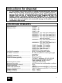
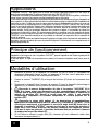
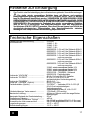
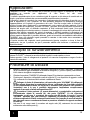
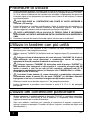
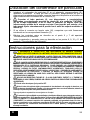
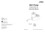
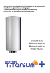
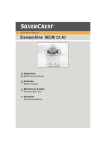
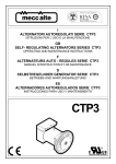
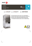
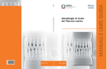
Collection liner for fluids suction canisters
Poche de recueil pour bocaux pour fluides aspirés
Flüssigkeitenabsaugbeutel
Sacchetto per contenitore di fluidi aspirati
Bolsa para el recipiente de succión de fluidos
Instructions of use
Mode d’emploi
Gebrauchsanweisung
Istruzioni per l’uso
Instrucciones de uso
Publ. code
Code de Publication
Kennzahl der Veröffentlichung
Codice di Pubblicazione
Código de Publicación 30751/015
Issue
Édition du
Auflage vom
Edizione del
Edición de
2010-09
0123
FLOVAC® is a trademark of FLOW METER S.p.A
(03)
K
B
M
I
L
G
H
A
E
D
P
C
F
J
Fig. 2
Fig. 1
N
O
P
Fig. 4
Fig. 3
2
SUCTION CANISTER LINER
Warning
General information
•
•
•
•
•
WARNING: DANGER INDICATION
Attention: Important indication
®
Read this manual carefully before using the FLOVAC fluid suction system.
AFTER UNPACKING, CHECK THAT THERE ARE NO PARTS MISSING OR
DAMAGED.
EACH TIME BEFORE USING THE DEVICE CARRY OUT THE OPERATIONS
DESCRIBED IN THE CHAPTER “START-UP PROCEDURE”.
The company will not accept any responsibility if these instructions are not
observed.
The medical device and its components or accessories do not contain parts in
natural rubber latex.
Connections
•
•
•
MAKE THE CONNECTIONS AND CHECK THE SEALS BETWEEN THE
COMPONENTS AS DESCRIBED IN “INSTRUCTIONS FOR USE” SECTION. NON
PERFORMANCE OF THESE CHECKS MAY COMPROMISE THE SAFETY AND
FUNCTIONING OF THE DEVICE AND ANY CONNECTED ACCESSORIES
(TUBES, PARTICLE CONTAINER, SUPPORT SYSTEMS, ETC).
ANY SUCTION ADJUSTMENT DEVICE CONNECTED AND THE CONNECTION
HOSES MUST COMPLY WITH EN ISO 10079-3 STANDARDS.
INADVERTENT INVERSION OF THE CONNECTIONS COULD LEAD TO
CONTAMINATION OF THE OPERATOR AND/OR OF THE VACUUM
GENERATING SYSTEM.
Operation
•
®
THE FLOVAC SUCTION LINERS MUST ALWAYS BE USED WITH CARE AND
ONLY BY PERSONNEL WHO ARE AWARE OF THE CONSEQUENCES OF
THE ONGOING THERAPY.
• FULL CONTAINERS MUST BE HANDLED WITH GREAT CARE DURING
TRANSFER TO THE DISPOSAL AREAS, FOLLOWING THE LOCAL
PROCEDURES AND REGULATIONS.
The device has been designed and manufactured in conformity with the safety
regulations established by standard EN ISO 10079-3.
Copyright ©
©
Copyright FLOW METER S.P.A. 2003-2010
All right reserved. None of the information contained in this publication must be used for
purposes other than the original ones. No part of this publication may be reproduced
without written permission. CA-MI S.r.l. devices are subjected to periodic revisions to
maintain and improve the production standards, functioning and increase their reliability.
For this reason, the contents of this publication may be modified at any time without prior
warning. The device described in this publication is designed and manufactured by
CA-MI S.r.l., Via Ugo La Malfa, 31 – 43010 PILASTRO (PR) – Italy.
GB
3
Applications
®
The FLOVAC suction liner is used to collect organic fluids by aspiration and has
been designed and manufactured for “High flow and high vacuum” applications
(EN ISO 10079-3).
It basically consists of a rigid supporting canister and of this disposable collection
system, the latter formed by a liner bag hermetically welded to the lid.
The lid has connectors that make it possible to connect the suction liner with the
vacuum line and with the patient. A hydrophobic shut off and antibacterial filter
protects the device and/or the vacuum system. This filter also operates as a an
overflow valve, deactivating vacuum generation whenever the specified maximum
filling limit is reached. The “PATIENT” port permits aspiration of fluids containing
bone fragments once the right-angled reducing connector has been removed. A
graduated scale printed on the external container makes it possible to monitor the
volume of liquid collected. The size of the device to be used can be chosen on the
basis of the real amount of fluid to be collected. Where a collection capacity greater
than the maximum available is needed, the connector “TANDEM” can be employed.
This permits connection of two or more equal devices to be joined in a stack, thus
increasing the system’s collection capacity.
The hermetic seal on the lid makes disposal particularly hygienic, simple and secure,
for the patient and for the personnel dealing with the removal and disposal of the
device.
Instructions for use
After connecting the “PATIENT”
port to the suction tube and the “VACUUM” port to
®
the vacuum line, the FLOVAC can be used for the safe and aseptic collection of
organic fluids.
Where specified, the patient connection tube and suction cannula are supplied with
the container kit.
Start-up procedure
1. Insert the liner bag (A) and, pressing firmly all around the edge, apply the lid (B)
to the reusable rigid container of the appropriate dimensions (C) (supplied
separately), making sure that the system is completely sealed.
2. Close the “TANDEM” (D) connector using the supplied tap (E) and pressing it
firmly.
3. Position the device in the appropriate ring support (F) with the sliding connection
device (G), ensuring that the system is vertical and firmly connected.
4.
Connect the vacuum feed source to the “VACUUM” port (H) using a
tube with suitable size and characteristics, ensuring that the butterfly
connection (I) is fully inserted in the cover and turned to “ON”. when the
canister is not in use, aspiration can be simply interrupted by turning the
butterfly connector to “OFF”.
5.
Connect a suitable patient tube (J) of appropriate dimensions and, if
necessary, fitted with a cannula (K), to the “PATIENT” port (L) on the lid using, if
necessary, the right-angled connector (M) supplied with the device. The
“PATIENT” port permits aspiration of fluids containing bone fragments once the
right-angled reducing connector has been removed. To prevent it from getting in
the way, the tube may be easily attached to the support ring using the spring (P).
6. When the right-angled connector is used (M), ensure that it is firmly held in port (L).
GB
4
Start-up procedure
7.
Before use, check all the seals and make sure that there are no leaks by turning
on the suction and blocking the cannula (K) connected to the “PATIENT” port
(L). There are no leaks in the system it the liner bag is fully extended, closely
adhering to the wall of the rigid container and the lid is slightly buckled towards
the inside of the canister.
8.
DO NOT USE A SOURCE OF VACUUM OF LESS THAN –750 mbar (-570
mmHg) WITH THIS CANISTER.
9.
Turn on the suction and check regularly the level inside the canister. The
vacuum check valve will interrupt suction if the fluid reaches the maximum level
envisaged for the canister.
10.
WHEN THE CHECK VALVE INTERVENES, IT IS NECESSARY TO
DISCONNECT THE VACUUM WITHIN A MAXIMUM OF 5 MIN.
11. Proceed as described in the instructions given in the “Instructions for disposal”
section.
Use of several units in tandem
1.
Fit the liner bags with the lids to all the canisters to be used, following the instructions
given in point 1 of the previous paragraph.
2.
Seal the “TANDEM” opening (D) on the last unit with the appropriate tap (E), pressing
firmly.
3.
Connect the vacuum feed source to the “VACUUM” port (H) of all units,
using tubes with suitable size and characteristics and suitable line splitters (N)
complete with exclusion taps (O).
4.
Connect the “TANDEM” port (D) of the first unit to the “PATIENT” port (L) of
the second unit, using the right angled connector (M) supplied with the kit.
Continue for all other canisters, using tubes (P) with suitable size and
characteristics (e.g. TANDEM tube Ø8x11 L=0.38m – FLOW METER Ref.
970010120).
5.
Connect the patient tube (J), with suitable dimensions and characteristics
and where necessary furnished with cannula (K), to “PATIENT” port (L) of the
last canister, using if necessary the right angled connector (M) supplied with the
kit.
6.
Carry out all the checks described in points 6 and 7 of the previous section.
7.
Start up suction and proceed as described in points 8, 9, 10 and 11 of the previous
section.
Use of the particle container
1.
If necessary, a particle container can be fitted (FLOW METER ref. 000036100) to the
FLOVAC device in order to hold the organic material necessary for laboratory analyses
in a suitable containment bag.
GB
5
Use of the particle container
2.
After having fitted the bag with cover to the support container, following the
instructions in the paragraph “Procedures for Use”, remove the right-angled
connector (M) from the port (L).
3.
Insert the particle container (Z) in the adapter (R), pressing the cover firmly down
around its entire edge, ensuring that the system is completely sealed. Connect the
device to the bag with cover, inserting it firmly in the port (L).
4.
Connect the patient tube (J) with suitable dimensions and possibly
equipped with a cannula (K) to the “PATIENT” port (S) of the cover, using if
necessary the right angled connector (M) previously removed from the bag
with cover. To avoid it causing an obstruction, the tube can be conveniently
fixed to the support ring using the spring (P).
5.
If the right-angled connector (M) is used, ensure that it is firmly inserted in its port (S).
6.
Perform checks as described in points 6 and 7 of the paragraph “Procedures for
Use”.
7.
Initiate aspiration and proceed as described in points 8, 9, 10, and 11 of the
paragraph “Procedures for Use”.
Instructions for disposal
1.
THE DEVICE IS INTENDED FOR SINGLE PATIENT APPLICATION. AVOID
RE.USE IN ORDER TO LIMIT THE RISK OF CROSS CONTAMINATION.
2.
TURN OFF THE VACUUM AND REMOVE ALL THE TUBES CONNECTED TO
THE LINER, GIVING PARTICULAR ATTENTION TO AVOID ACCIDENTAL
CONTAMINATION. IF RIGHT-ANGLED CONNECTOR HAS BEEN USED, THIS
MUST BE REMOVED.
3.
IF THE PARTICLE CONTAINER IS USED, IT MUST BE REMOVED
IMMEDIATELY AFTER THE CONTAINER’S DEACTIVATION TO AVOID
DEGRADATION OF THE COLLECTED PARTICLES. THEN CONNECT THE
APPROPRIATE STOPPERS (U – V) TO THE “PATIENT” CONNECTORS (S) AND (T),
PRESSING HARD, BEING CAREFUL TO AVOID ACCIDENTAL CONTAMINATION.
TRANSFER THE SUITABLY IDENTIFIED DEVICE TO THE LABORATORY, AND
AFTER HAVING OPENED THE PARTICLE CONTAINER AND CUT THE INTERNAL
CONTAINMENT BAG (Q), RESPECTING THE HOSPITAL’S APPLICABLE
REGULATIONS, THE ORGANIC MATERIAL TO BE ANALYSED CAN BE REMOVED.
4.
FIT THE APPROPRIATE PLUGS (E – P) TO THE “PATIENT” (L) AND
“TANDEM” (D) PORTS, PRESSING THEM HOME FIRMLY, TAKING CARE TO
AVOID ACCIDENTAL CONTAMINATION.
5.
Turn the butterfly connector (I) to “OFF”.
6.
Remove the liner bag from the rigid container and transfer it to the waste
disposal area, ensuring that all the openings are sealed, as well as any used
tubes and cannulas, keeping in mind that the product is potentially infectious.
7.
The product must be disposed of in accordance with the current hospital regulations.
GB
6
Instructions for disposal
7.
The reusable rigid canister must be cleaned and disinfected with water and
neutral detergents and/or sterilised in an autoclave a 121 °C (relative pressure 1
bar) for 15 min. DO NOT USE SOLVENTS OR ALCOHOL FOR CLEANING AND
DISINFECTION: THE USE OF THESE PRODUCTS MAY DAMAGE THE UNIT. The
reusable canister mechanical resistance is guaranteed for 30 cleaning and
sterilisation cycles under the specified conditions (EN ISO 10079-3). beyond this limit
it may show signs of physical and mechanical damage to the plastic and its
substitution is thus advised.
Technical features
Sales description ..........................................
Reference code ............................................
“VACUUM” connector ..................................
“PATIENT” connector...................................
“TANDEM” connector...................................
“TANDEM” tube (optional) ..........................
Particle container (optional) .........................
Maximum vacuum value...............................
Maximum flow value .....................................
Maximum graduation interval........................
Gradation precision .......................................
Patient tube dimensions...............................
Vacuum tube dimensions .............................
Storage conditions ........................................
Working conditions .......................................
GB
®
FLOVAC
31845 - 1.0 L
31846 - 2.0 L
31847 - 3.0 L
000036030 - 1.0 L with 1.8m tube Ø 8x11
000036031 - 2.0 L with 1.8m tube Ø 8x11
000036032 - 3.0 L with 1.8m tube Ø 8x11
000036050 - 1.0 L with 1.8m tube Ø 8x11
and vacuum stop
000036051 - 2.0 L with 1.8m tubo Ø 8x11
and vacuum stop
000036052 - 3.0 L with 1.8m tubo Ø 8x11
and vacuum stop
31840 - Reusable 1.0 L canister
31841 - Reusable 2.0 L canister
31842 - Reusable 3.0 L canister
970010120 - TANDEM tube
000036100 - Particle container
Ø 9.0÷10.0 with ON-OFF switch
Ø 14.0÷15.5 (Ø 8.0÷9.2 with right-angled
connector)
Ø 8.0÷9.2
Ø 8x11 L=0.38m
“PATIENT” connector: Ø 14.0÷15.5 (Ø
8.0÷9.2 with right-angled connector)
Outlet connector: Ø 14.0÷15.5 F.
-750 mbar (-570 mmHg)
42 LPM under the recommended conditions
50 ml
±50 ml
Min. Ø 6x9 (recommended Ø 8x11 L=2.5m max)
Min. Ø 6x9 (recommended Ø 8x11 L=1.8m max)
-40 °C ÷ +60 °C
-18 °C ÷ +50 °C
7
POCHE DE RECUEIL D’ASPIRATION
Avertissements
AVERTISSEMENT: INDICATION DE DANGER
Attention: Indication importante
Information générales
•
•
•
•
•
Lire attentivement les informations figurant dans
cette notice avant d'utiliser
®
le système d'aspiration de liquides FLOVAC .
APRES LE DEBALLAGE, IL EST NECESSAIRE DE VERIFIER L'INTEGRITE
DU DISPOSITIF.
AVANT CHAQUE UTILISATION, EFFECTUER LES OPERATIONS DECRITES
DANS LE CHAPITRE “MODALITES D’UTILISATION”.
La société décline toute responsabilité en cas de non-observation des présentes
instructions.
Le dispositif et ses parties composantes ou accessoires ne contiennent aucune
partie en latex.
Connexions
•
•
•
EFFECTUER LES RACCORDEMENTS ET LES CONTROLES D'ETANCHEITE DES
COMPOSANTS SUIVANT LA DESCRIPTION DONNEE AU CHAPITRE "MODALITES
D'UTILISATION". L’OMISSION DE CES CONTRÔLES PEUT NUIRE À LA SÉCURITÉ
ET AU BON FONCTIONNEMENT DU DISPOSITIF ET DE SES ÉVENTUELS
ACCESSOIRES (TUYAUX, SYSTÈME DE RÉCOLTE POUR PARTICULES,
SYSTÈMES DE SUPPORT, ETC.).
LES DISPOSITIFS DE REGLAGE DU VIDE EVENTUELLEMENT RACCORDES ET LES
TUYAUX DE CONNEXION DOIVENT ETRE CONFORMES A LA NORME EN ISO 10079-3.
UNE INVERSION FORTUITE DES RACCORDEMENTS PEUT CAUSER UNE
CONTAMINATION DE L'OPERATEUR ET/OU DE L'INSTALLATION DE
PRODUCTION DU VIDE.
Opérations
•
®
LES BOCAUX DE RÉCOLTE DE LIQUIDES ASPIRES FLOVAC DOIVENT ETRE
UTILISES AVEC ATTENTION ET SEULEMENT PAR DU PERSONNEL INFORME
DES CONSEQUENCES DERIVANT DE LA THERAPIE EN COURS.
• MANIPULER AVEC SOIN LES BOCAUX PLEINS DURANT LE TRANSPORT
DANS LES ZONES DESTINEES A LA MISE AU REBUT, EN SUIVANT LES
PROCEDURES EN VIGUEUR DANS L’HOPITAL.
Le dispositif a été conçu et fabriqué pour satisfaire les critères de sécurité de la
norme EN ISO 10079-3.
Copyright ©
©
Copyright FLOW METER S.P.A. 2003-2010
Tous droits réservés. Toutes les informations contenues dans la présente publication ne
peuvent pas être utilisées dans d’autres buts que ceux qui en sont à l’origine. La
publication ne peut pas être reproduite, ni partiellement nientièrement, sans accord écrit.
Afin de maintenir et d’amèliorer les caractéristiques standard de production et de
fonctionnement et d’agumenter la fiabilité, les dispositifs CA-MI S.r.l. sont régulièrement
modernisés; c’est pourquoi que les contenus de cette publication sont sujets à des
modifications sans préavis. Le dispositif décrit dans la présente publication est projeté et
construit pour CA-MI S.r.l., Via Ugo La Malfa, 31 – 43010 PILASTRO (PR) – Italie.
F
8
Applications
®
Le dispositif FLOVAC est utilisé pour la récolte des fluides organiques aspirés et a été conçu et
fabriqué pour applications de “Flux élevé et pour haut vide” (EN ISO 10079-3).
Le dispositif est constitué essentiellement d'un bocal rigide de support et de ce système collecteur à
usage unique composé d'une poche soudée hermétiquement au couvercle.
Le couvercle est muni de raccords qui permettent le raccordement du bocal avec la ligne d'aspiration et
avec le patient. Un filtre hydrophobe anti-reflux et anti-bactéries protège le dispositif et/ou l'installation de
production du vide. Ce filtre sert aussi de vanne de trop plein en désactivant la production du vide si le
niveau maximum de remplissage prévu a été atteint. L’ouverture “PATIENT” permet, une fois qu’a été
enlevé le raccord de réduction à angle droit, d'effectuer l'aspiration de fluides contenant des fragments
osseux. Une échelle graduée, imprimée sur l'extérieur du bocal, permet de contrôler le volume des
liquides récoltés. Selon les nécessités effectives des volumes à aspirer, il est possible de choisir les
dimensions du dispositif à utiliser. S’il est nécessaire d’avoir un système avec une capacité de récolte
dépassant le volume maximum disponible, il est possible d’ajouter, grâce au raccord portant la mention
“TANDEM”, deux dispositifs identiques en les mettant en cascade: on augmente ainsi la capacité de
récolte du système.
L'herméticité du couvercle rend particulièrement hygiénique, simple et sûre la phase de manipulation et
élimination, tant pour le patient que pour le personnel préposé à l'enlèvement et au remplacement du
dispositif proprement dit.
Principe de fonctionnement
Une fois que les ouvertures “PATIENT” et “VACUUM”® ont été raccordées respectivement au tuyau
d'aspiration et à la ligne du vide, le système FLOVAC permet l'aspiration des fluides organiques de
manière aseptique et sûre.
Si cela est prévu, le tuyau de raccordement au patient et la canule d’aspiration sont fournis avec le
bocal.
Modalités d’utilisation
1.
Introduire la poche (A) et appliquer le couvercle (B) sur le bocal (C) réutilisable de
dimensions adéquates (fourni à part), en appuyant à fond sur tout le périmètre et en
contrôlant que le système est hermétiquement fermé.
2.
Fermer le raccord “TANDEM” (D) au moyen du bouchon (E) fourni en le pressant avec
force.
3.
Positionner le dispositif dans l’anneau de support (F) avec le dispositif d’accrochage à
glissière (G), en vérifiant que le système est vertical et solidement fixé.
4.
Raccorder la source d’alimentation du vide à l’ouverture “VACUUM” (H) à
l’aide d’un tuyau ayant des dimensions et des caractéristiques adéquates, en
vérifiant que le raccord papillon (I) est complètement inséré dans le couvercle et
orienté en position ON. Quand le bocal n’est pas utilisé, il est possible
d‘interrompre l’aspiration en tournant simplement le raccord papillon sur la
position OFF.
5.
Raccorder le tuyau côté patient (J), de dimensions et caractéristiques
appropriées et éventuellement muni de canule (K), à l'ouverture “PATIENT” (L) du
couvercle en employant, si nécessaire le raccord à angle droit (M) fourni avec le
dispositif. L’ouverture “PATIENT” permet, une fois que le raccord de réduction à
angle droit a été enlevé, d’aspirer des fluides contenant des fragments osseux.
Pour que le tuyau ne gêne pas, il peut être facilement fixé par pression à l’anneau
de support au moyen du ressort (P).
6.
Si l’on utilise le raccord à angle droit (M), s’assurer qu’il est solidement inséré dans
l’ouverture correspondante (L).
F
9
Modalités d’utilisation
7.
Avant d'utiliser le dispositif, contrôler toutes les fermetures et vérifier qu'il n'y a pas de
fuites en mettant en marche la source d'aspiration et en bouchant la canule (K) raccordée
à l'ouverture “PATIENT” (L). Si la poche se déploie à l'intérieur du bocal et adhère
complètement à la paroi et si on observe une déformation du couvercle vers l'intérieur,
cela signifie que le système ne présente pas de fuites.
8.
NE PAS APPLIQUER AU DISPOSITIF UNE SOURCE DE VIDE INFERIEURE A 750 MBAR (-570 MMHG).
9.
Commencer l'aspiration et contrôler périodiquement le niveau de remplissage du bocal.
La valve du vide causera l'interruption de l'aspiration si les fluides aspirés ont atteint le
niveau maximum de remplissage prévu pour le dispositif.
10.
APRES L'INTERVENTION DE LA VALVE DE TROP PLEIN, IL FAUT
DECONNECTER LA SOURCE D'ASPIRATION AU MAXIMUM DANS LES
5 MINUTES QUI SUIVENT.
11. Procéder suivant les instructions fournies dans le chapitre “Instructions pour la mise au rebut”.
Utilisation en tandem avec plusieurs unités
1.
Appliquer les poches avec couvercle à tous les bocaux à utiliser en suivant les
instructions données au point 1 du paragraphe précédent.
2.
Fermer hermétiquement l’ouverture “TANDEM” (D) de la dernière unité avec le
bouchon (E) en le pressant avec force.
3.
Raccorder la source d’alimentation du vide aux ouvertures “VACUUM”
(H) de toutes les unités en utilisant des tuyaux ayant des dimensions et
des caractéristiques adéquates et des dédoubleurs de ligne (N) appropriés
avec robinets d’exclusion (O).
4.
Raccorder l’ouverture “TANDEM” (D) de la première unité à l’ouverture
“PATIENT” (L) de la deuxième unité, en utilisant pour ce faire le raccord à
angle droit (M) fourni, et ainsi de suite pour tous les autres bocaux, au
moyen de tuyaux (P) ayant des dimensions et des caractéristiques
adéquates (par exemple tuyau TANDEM Ø8x11 L=0.38m – FLOW METER
Ref. 970010120).
5.
Raccorder le tuyau du patient (J), ayant des dimensions et des
caractéristiques adéquates et éventuellement pourvu d’une canule (K), à
l’ouverture “PATIENT” (L) du dernier couvercle en utilisant, le cas échéant, le
raccord à angle droit (M) fourni.
6.
Effectuer les contrôles selon les descriptions des points 6 et 7 du paragraphe précédent.
7.
Commencer l'aspiration et procéder suivant les indications des points 8, 9, 10 et
11 du chapitre précédent.
Utilisation du système de récolte pour particules
1.
Si nécessaire, il est possible d’adapter au dispositif FLOVAC un système de
récolte pour particules (FLOW METER Réf. 000036100) afin de retenir dans une
maille la matière organique nécessaire pour les analyses de laboratoire.
2.
Après avoir adapté le sachet avec couvercle au récipient de support, en suivant
les instructions du paragraphe “Procédures d’utilisation”, enlever le raccord à
angle droit (M) de l’ouverture (L).
F
10
Utilisation du système de récolte pour particules
3.
Assembler le système de récolte pour particules (Z) à l’adaptateur prévu à cet
effet (R), en appuyant fort sur le couvercle sur tout le périmètre et en s’assurant
que le système est complètement scellé, puis raccorder le dispositif au sachet
avec couvercle en l’insérant solidement dans l’ouverture (L).
4.
Raccorder le tuyau du patient (J), ayant des dimensions et des
caractéristiques adéquates et éventuellement pourvu d’une canule (K), à
l’ouverture “PATIENT” (S) du couvercle en utilisant, le cas échéant, le
raccord à angle droit (M) précédemment enlevé du sachet avec couvercle.
Pour qu’il ne gêne pas, ce tuyau peut être aisément fixé par pression à
l’anneau de support au moyen d’un ressort (P).
5.
Si l’on utilise le raccord à angle droit (M), s’assurer qu’il est solidement inséré
dans l’ouverture correspondante (S).
6.
Effectuer les contrôles décrits aux points 6 et 7 du paragraphe “Procédures
d’utilisation”.
7.
Commencer l’aspiration et suivre les instructions des points 8, 9, 10 et 11 du
paragraphe “Procédures d’utilisation”.
Instructions pour la mise au rebut
1.
LE DISPOSITIF EST CONÇU POUR APPLICATION A UN SEUL PATIENT.
EVITER DE LE REUTILISER POUR LIMITER LE RISQUE DE CONTAMINATION
CROISEE.
2.
DESACTIVER LA SOURCE D'ASPIRATION ET ENLEVER TOUS LES
TUYAUX RACCORDÉS AU BOCAL EN FAISANT PARTICULIEREMENT
ATTENTION A EVITER TOUTE CONTAMINATION ACCIDENTELLE. SI LE
RACCORD A ANGLE DROIT A ETE UTILISE, IL EST NECESSAIRE DE
L’ENLEVER.
3.
SI ON A UTILISÉ LE SYSTÈME DE RÉCOLTE POUR PARTICULES, IL EST
NÉCESSAIRE DE L’ENLEVER TOUT DE SUITE APRÈS LA DÉSACTIVATION DU
BOCAL POUR ÉVITER LA DÉGRADATION DES PARTICULES RECUEILLIES.
APPLIQUER LES BOUCHONS PRÉVUS (U – V) SUR LES RACCORDS « PATIENT »
(S) ET (T), EN EXERÇANT UNE FORTE PRESSION ET EN VEILLANT TOUT
PARTICULIÈREMENT À ÉVITER LES CONTAMINATIONS ACCIDENTELLES.
ENSUITE, TRANSFÉRER LE DISPOSITIF, ADÉQUATEMENT IDENTIFIÉ, AU
LABORATOIRE ET, APRÈS AVOIR OUVERT LE SYSTÈME DE RÉCOLTE POUR
PARTICULES ET COUPÉ LA MAILLE INTERNE CONTENANT LES PARTICULES (Q)
EN RESPECTANT LES NORMES EN VIGUEUR DANS L’HÔPITAL , IL SERA
POSSIBLE DE PRÉLEVER LA MATIÈRE ORGANIQUE POUR LES ANALYSES.
4.
APPLIQUER LES BOUCHONS PREVUS (E – P) A CET EFFET AUX RACCORDS,
“PATIENT” (L) ET “TANDEM” (D) EN LES ENFONÇANT A FOND ET EN FAISANT
PARTICULIEREMENT
ATTENTION
A
EVITER
TOUTE
CONTAMINATION
ACCIDENTELLE.
Tourner le raccord papillon (I) sur la position OFF.
5.
6.
Enlever la poche du bocal et la transporter dans la zone de collecte des déchets, avec
toutes les ouvertures hermétiquement fermées ainsi que les éventuels tuyaux avec
canules employés, en considérant que le produit est potentiellement infecté.ù
6.
Mettre le produit au rebut en respectant les normes en vigueur dans l’hôpital.
F
11
Instructions pour la mise au rebut
7.
Le bocal rigide réutilisable peut être nettoyé et désinfecté avec de l’eau et des
détergents neutres et/ou stérilisé dans un autoclave à 121 °C (pression relative 1 bar)
pendant 15 min. NE PAS UTILISER DE SOLVANTS OU D'ALCOOL POUR LE LAVAGE ET
LA DESINFECTION: L'UTILISATION DE CES PRODUITS PEUT ENDOMMAGER CE
COMPOSANT. La resistance mecanique du bocal reutilisable est garantie jusqu'a 30
cycles de nettoyage et de sterilisation aux conditions specifiees (EN ISO 10079-3). au-dela
de cette limite, les caracteristiques physiques et mecaniques de la matiere plastique
peuvent se degrader et il est donc conseille de le remplacer.
Caractéristiques techniques
Description Commerciale.............................
Codes de référence .....................................
®
FLOVAC
31845 - 1.0 L
31846 - 2.0 L
31847 - 3.0 L
000036030 - 1.0 L avec 1.8m tuyau Ø 8x11
000036031 - 2.0 L avec 1.8m tuyau Ø 8x11
000036032 - 3.0 L avec 1.8m tuyau Ø 8x11
000036050 - 1.0 L avec 1.8m tuyau Ø 8x11
et stop-vide (vacuum stop)
000036051 - 2.0 L avec 1.8m tuyau Ø 8x11
et stop-vide (vacuum stop)
000036052 - 3.0 L avec 1.8m tuyau Ø 8x11
et stop-vide (vacuum stop)
31840 - Canister réutilisable 1.0 L
31841 - Canister réutilisable 2.0 L
31842 - Canister réutilisable 3.0 L
970010120 - Tuyau TANDEM
000036100 - Système de récolte pour
Raccord “VACUUM”..................................... particules
Raccord “PATIENT” ..................................... Ø 9.0÷10.0 avec interrupteur ON-OFF
Ø 14.0÷15.5 (Ø 8.0÷9.2 avec raccord à
Raccord “TANDEM” ..................................... angle droit)
Tuyau “TANDEM” (en option)...................... Ø 8.0÷9.2
Système de récolte pour particules (en Ø 8x11 L=0.38m
option) ........................................................... Raccord “PATIENT”: Ø 14.0÷15.5 (Ø
8.0÷9.2 raccord à angle droit)
Raccord de sortie: Ø 14.0÷15.5 F.
Valeur maximum de vide ........................... -750 mbar (-570 mmHg)
Valeur maximum de débit .......................... 42 LPM dans les conditions conseillées
Intervalle maximum de la graduation ....... 50 ml
Précision de la graduation ........................... ±50 ml
Dimensions du tuyau du patient ............... Min. Ø 6x9 (conseillé Ø 8x11 L=2.5m max)
Dimensions du tuyau d'alimentation......... Min. Ø 6x9 (conseillé Ø 8x11 L=1.8m max)
Conditions de stockage .............................. -40 °C ÷ +60 °C
Conditions d'emploi................................. -18 °C ÷ +50 °C
F
12
ABSAUGBEUTEL
Hinweis
HINWEIS: GEFAHRENBEREICH
Achtung: Wichtiger Hinweis
Allgemeine Informationen
•
•
•
•
•
®
Vor der Anwendung des Absaugbehälters FLOVAC sind die Angaben des
vorliegenden Dokuments aufmerksam zu lesen.
ÜBERPRÜFEN SIE DAS GERÄT NACH DEM ENTFERNEN DER
VERPACKUNG AUF EVENTUELLE FEHLER ODER SCHÄDEN.
VOR JEDER INBETRIEBNAHME DES GERÄTS IST DEN ANGABEN DES
KAPITELS “ANWENDUNG” FOLGE ZU LEISTEN.
Der Hersteller kann unter keinen Umständen für Schäden, die auf das
Nichtbeachten der vorliegenden Gebrauchsanleitung, zurückgehen haftbar
gemacht werden.
Das Medizinprodukt und seine Bestandteile und Zusatzgeräte enthalten keine
Teile aus natürlichen Latex.
Anschlüsse
•
•
•
DIE KONTROLLE DER ANSCHLÜSSE UND DICHTUNGEN DER EINZELNEN
KOMPONENTEN SIND DEM KAPITEL “ANWENDUNG” FOLGEND
DURCHZUFÜHREN. DURCH UNTERLASSEN DIESER KONTROLLEN KANN
DIE SICHERHEIT UND DIE FUNKTIONALITÄT DER VORRICHTUNG, SOWIE
DER EVENTUELL ANGESCHLOSSENEN ZUBEHÖRTEILE (SCHLÄUCHE,
PARTIKELBEHÄLTER, TRAGESYSTEME, USW.) BEEINTRÄCHTIGT WERDEN.
GEGEBENENFALLS ANGESCHLOSSENE VORRICHTUNGEN ZUR REGULIERUNG
UND MESSUNG DES VAKUUMS UND DIE VERBINDUNGSSCHLÄUCHE HABEN DER
VORSCHRIFT EN ISO 10079-3 ZU ENTSPRECHEN.
EIN UNGEWOLLTES VERTAUSCHEN DER ANSCHLÜSSE KANN DIE SICHERHEIT
DES BENUTZERS GEFÄHRDEN UND/ODER DIE VAKUUMANLAGE BESCHÄDIGEN.
Arbeitsgänge
•
®
DIE ABSAUGBEUTEL FLOVAC DÜRFEN AUSSCHLIEßLICH MIT GRÖßTER
SORGFALT UND VON PERSONEN, DIE MIT DER ABSAUGUNG VON PATIENTEN
VERTAUT SIND, BENÜTZT WERDEN.
• BEIM TRANSPORT DER VOLLEN BEHÄLTER ZU DEN ENTSORGUNGSSTELLEN HAT
ÄUßERSTE VORSICHT ZU WALTEN UND DIE VON DER ZUSTÄNDIGEN BEHÖRDE
VORGESCHRIEBENEN NORMEN HABEN AUSNAHMSLOS BEFOLGT ZU WERDEN.
Das Gerät wurde den Sicherheitskriterien der Vorschrift EN ISO 10079-3
entsprechend entwickelt und hergestellt.
Copyright ©
©
Copyright FLOW METER S.P.A. 2003-2010
Alle Rechte vorbehalten. Sämtliche, in vorliegender Veröffentlichung enthaltenen
Informationen haben ausnahmslos für den dafür bestimmten Zweck verwendet zu werden.
Die auszugsweise oder gesamte Wiedergabe der Texte ist ohne schriftliche Genehmigung
strengstens untersagt. Aus Gründen der Beibehaltung und Verbesserung des
Produktionsstandard, der Funktionsweise und Zuverlässigkeit der Produkte behält sich die
Firma CA-MI S.r.l. das Recht vor, den Inhalt der vorliegenden Veröffentlichung nach
Belieben und ohne vorherige Ankündigung abzuändern. Die in vorliegender
Veröffentlichung beschriebene Vorrichtung wurde von der Firma CA-MI S.r.l. Via Ugo La
Malfa, 31 – 43010 PILASTRO (PR) – Italien entwickelt und hergestellt.
D
13
Anwendungsbereich
®
Das System FLOVAC dient zur Aufnahme organischer Flüssigkeiten und ist zur Anwendung mit
Hohem Flüssigkeitfluss und Vakuum entwickelt und hergestellt (EN ISO 10079-3).
Das Absaugsystem setzt sich grundsätzlich aus einem Außenbehälter und einem hermetisch am
Deckel abgeschlossenem Beutel zusammen. Der Deckel verfügt über Verbinder, die den
Anschluß des Behälters an die Absaugleitung und an den Patienten ermöglichen. Ein
hydrophober Filter mit Rückström- und Bakterienschutz sichert das Gerät und/oder die
Vakuumanlage ab. Dieser Filter fungiert außerdem als Überlaufventil, indem er die
Vakuumerzeugung ausschaltet, sobald der maximal vorgesehene Füllpegel erreicht ist. Der
“PATIENT”-Anschluss ermöglicht nach Entfernung des rechtwinkligen Reduzierverbinders die
Ansaugung von Flüssigkeiten, die Knochensplitterrückstände enthalten. Eine auf den Behälter
aufgedruckte Maßskala ermöglicht die Volumenkontrolle der abgesaugten Flüssigkeit. Je nach
Wunsch stehen verschiedene Grössen zur Verfügung. Falls ein System gewünscht wird, das
eine Sammelkapazität aufweist, die über das maximal verfügbare Volumen hinausgeht, können
dank dem mit der Beschriftung “TANDEM” gekennzeichneten Verbinder zwei oder mehrere
gleiche Vorrichtungen in Kaskadenschaltung angeordnet werden: auf diese Weise wird die
Sammelfähigkeit des Systems erhöht.
Die hermetische Abdichtung des Deckels garantiert sowohl den Patienten, als auch dem zur
Entfernung oder zum Wechsel des Geräts befugten Personal ein Maximum an Hygiene und
Sicherheit während der Entsorgungsphase.
Funktionsprinzip
Nach Anschluß der Ausgänge “PATIENT” an den® Saugschlauch und “VACUUM” an die
Vakuumanlage, gewährleistet das System FLOVAC ein aseptisches und sicheres Absaugen
der organischen Flüssigkeiten.
Falls vorgesehen, werden der Verbindungsschlauch zum Patienten und die Saugkanüle
zusammen mit dem Behälter geliefert.
Anwendung
1.
2.
3.
Den Beutel (A) einsetzen und den Deckel (B) auf den Außenbehälter (C) aufsetzen. Der Deckel
sollte fest angedrückt werden. Der Außenbehälter ist wieder verwenbar. Versichern Sie sich, daß
das gesammte System dicht ist.
Den Verbinder “ TANDEM” (D) schließen, indem man den zur Ausstattung gehörenden
Verschluss (E) verwendet und fest andrückt.
Die Vorrichtung in dem entsprechenden Haltering (F) mit dem Kupplungsschlitten (G) anordnen
und sich dabei vergewissern, dass das System senkrecht und einwandfrei befestigt ist..
4.
Die Vakuumzufuhr mit dem Anschluss “ VACUUM” (H) verbinden und dazu
einen Schlauch mit den entsprechenden Abmessungen und Eigenschaften
verwenden; sich dabei vergewissern, dass die Drosselverbindung (l) ganz im
Deckel liegt und auf Stellung ON steht. Wird der Behälter nicht verwendet, kann
die Ansaugung unterbrochen werden, indem man die Drossel einfach auf OFF
stellt.
5.
Den Schlauch (J) zum Patienten an den Ausgang “ PATIENT” (L) des
Deckels anschließen. Verwenden Sie dazu einen Schlauch (eventuell mit Kanüle
(K)) mit entsprechenden Ausmaßen und Eigenschaften, sowie falls nötig das
mitgelieferte, rechtwinkelige Verbindungsstück (M). Der “ PATIENT” -Anschluss
ermöglicht die Ansaugung von Flüssigkeiten mit Knochensplitterrückständen
nach Entfernung des rechtwinkligen Reduzierverbinders. Um zu vermeiden,
dass er hinderlich wird, kann der Schlauch mit Hilfe der Feder (P) per Druck
bequem am Haltering befestigt werden.
Wird der rechtwinklige Verbinder (M) verwendet, muss sichergestellt werden, dass er fest in den
entsprechenden Anschluss (L) eingesetzt ist.
6.
D
14
Anwendung
7.
Bevor das Gerät erstmalig in Betrieb genommen wird, sollte dieses hinsichtlich seiner Dichtheit
kontrolliert werden. Schalten Sie dazu die Sauganlage ein und verschließen Sie die an den
Ausgang “PATIENT” (L) angeschlossene Kanüle (K). Die Dichtheit des Systems ist dann
gewährleistet, sobald der Beutel rundum am starren Behälter anliegt und der Deckel eine
Wölbung in Richtung Behälterinnenraum aufweist.
8.
DEN ABSAUGBEUTEL NICHT AN EINE VAKUUMANLAGE MIT EINEM SOG DER
GERINGER ALS -750 mbar (-570 mm Hg) IST ANSCHLIESSEN.
9.
Mit dem Absaugen beginnen und den Füllstand des Behälters in regelmäßigen Abständen
überprüfen. Erreicht die abgesaugte Flüssigkeit den für das Gerät höchstzulässigen Füllstand,
unterbricht der Überlaufschutz der Vakuumanlage den Absaugvorgang.
10.
WURDE DER ÜBERLAUFSCHUTZ AUSGELÖST, MUß DIE SAUGANLAGE
INNERHALB VON 5 MIN. ABGESCHALTET WERDEN.
11.
Gemäß den Angaben unter Kapitel “Hinweise zur Entsorgung” fortfahren.
Tandemfunktion mit mehr als einem Gerät
1.
Setzen Sie nun Beutel samt Deckel, den Angaben unter Punkt 1 folgend, auf alle zu
verwendenden Behälter.
2.
Die Öffnung “TANDEM” (D) der letzten Einheit mit dem entsprechenden Verschluss (E)
versiegeln und ihn fest andrücken.
3.
Die Vakuumzufuhr mit den “VACUUM”-Anschlüssen (H) sämtlicher Einheiten
verbinden und dabei Schläuche mit geeigneten Abmessungen und Eigenschaften
sowie entsprechende Leitungsverdoppler (N), komplett mit Sperrhähnen (O),
verwenden.
4.
Die “TANDEM”-Öffnung (D) der ersten Einheit mit der “ PATIENT” -Öffnung (L)
der zweiten Einheit verbinden und zu diesem Zweck den zur Ausstattung
gehörenden rechtwinkligen Verbinder (M) verwenden, und so bei allen übrigen
Behältern verfahren, wobei man jeweils Schläuche (P) mit geeigneten Abmessungen
und Eigenschaften verwendet (zum Beispiel TANDEM-Schlauch Ø8x11 L=0.38 –
FLOW METER Ref. 970010120).
5.
Den Patientenschlauch (J), der entsprechende Abmessungen und
Eigenschaften aufweisen und eventuell mit einer Kanüle (K) ausgerüstet sein muss,
mit dem “ PATIENT” -Anschluss (L) des letzten Deckels verbinden, wobei falls
erforderlich der zur Ausstattung gehörende rechtwinklige Verbinder (M) verwendet
wird.
6.
Führen Sie nun die unter Punkt 6 und 7 des vorangehenden Kapitels angeführten
Kontrollen aus.
7.
Mit dem Absaugvorgang beginnen und, wie unter den Punkten 8, 9, 10 und 11 des
vorangehenden Kapitels angeführt, fortfahren.
Gebrauch des Partikelbehälters
1.
Im Bedarfsfall kann an die Vorrichtung FLOVAC ein Partikelbehälter angepasst werden
(FLOW METER Art. Nr. 000036100), um das für die Laboruntersuchungen erforderliche
organische Material in einem Geflecht zurückzuhalten.
D
15
Gebrauch des Partikelbehälters
2.
Nachdem der Beutel mit Deckel wie im Abschnitt "Gebrauchsanleitungen" beschrieben an
den Tragebehälter angepasst wurde, den rechtwinkligen Verbinder (M) vom Anschluss (L)
entfernen.
3.
Den Partikelbehälter (Z) in den entsprechenden Adapter (R) stecken, dabei den Deckel
rundum fest andrücken und sicherstellen, dass das ganze System dicht geschlossen ist;
anschließend die Vorrichtung am Beutel mit Deckel anschließen und fest in den Anschluss
(L) stecken.
4.
Den Patientenschlauch (J), der entsprechende Abmessungen und
Eigenschaften aufweisen und eventuell mit einer Kanüle (K) ausgerüstet sein muss,
mit dem "PATIENT"-Anschluss (S) des Deckels verbinden, wobei falls erforderlich
rechtwinklige Verbinder (M) zu verwenden ist, der zuvor vom Beutel mit Deckel
entfernt wurde. Um zu vermeiden, dass er hinderlich wird, kann der Schlauch mit
Hilfe der Feder (P) per Druck bequem am Haltering befestigt werden.
5.
Wird der rechtwinklige Verbinder (M) verwendet, muss sichergestellt werden, dass er fest in
den entsprechenden Anschluss (S) eingesetzt ist.
6.
Die Kontrollen wie unter Punkt 6 und 7 des Abschnitts “Gebrauchsanleitungen” beschrieben
durchführen.
7.
Die Ansaugung beginnen und wie unter den Punkten 8, 9, 10 und 11 des Abschnitts
“Gebrauchsanleitungen” beschrieben vorgehen.
Hinweise zur Entsorgung
1.
DAS GERÄT IST ZUM EINZELPATIENTENGEBRAUCH HERGESTELLT. DAS
WIEDERGEBRAUCH MUSS VERHINDERT WERDEN, UM KONTAMINATIONS RISIKO ZU
HINDERN.
2.
DIE SAUGANLAGE ABSCHALTEN UND SÄMTLICHE AM BEHÄLTER
ANGESCHLOSSENEN SCHLÄUCHE ENTFERNEN. DABEI IST BESONDERS DARAUF ZU
ACHTEN, KEINE UNGEWOLLTEN VERUNREINIGUNGEN ZU VERURSACHEN. FALLS DER
RECHTWINKLIGE VERBINDER VERWENDET WURDE, MUSS ER ENTFERNT WERDEN.
3.
FALLS DER PARTIKELBEHÄLTER BENUTZT WURDE, MUSS ER SOFORT NACH
DEAKTIVIERUNG DES BEHÄLTERS ENTFERNT WERDEN, DAMIT DIE GESAMMELTEN
PARTIKEL NICHT VERDERBEN. DANN DIE DECKEL (U – V) AN DEN “PATIENT”-VERBINDERN
(S) UND (T) AUFSETZEN; DABEI FEST ZUDRÜCKEN UND JEDE KONTAMINATION
UNBEDINGT VERMEIDEN. ANSCHLIESSEND DIE ZWECKMÄSSIG GEKENNZEICHNETE
VORRICHTUNG AN DAS LABOR WEITERLEITEN. NACHDEM DER PARTIKELBEHÄLTER
GEÖFFNET UND DAS GEFLECHT IM INNERN (Q) UNTER BEFOLGUNG DER IM
KRANKENHAUS GELTENDEN VORSCHRIFTEN AUFGESCHNITTEN WURDE, KANN DAS
ORGANISCHE MATERIAL FÜR DIE UNTERSUCHUNG ENTNOMMEN WERDEN.
4.
DIE PFROPFEN (E – P) AUF DIE VERBINDER “PATIENT” (L) UND “TANDEM” (D)
AUFDRÜCKEN, WOBEI DARAUF ZU ACHTEN IST, DAß KEINE FLÜSSIGKEIT AUSLÄUFT.
Die Drossel (l) auf OFF stellen.
5.
6.
Den Beutel aus dem Außenbehälter nehmen und zur Entsorgungsstelle bringen. Dabei
müssen sämtliche Öffnungen einwandfrei verschlossen werden. Beim Transport der bereits
verwendeten Beutel und Schläuche (inklusive eventueller Kanülen) ist zu bedenken, daß der
Inhalt - und damit auch die einzelnen Komponenten - infektiös sein könnten.
D
16
Hinweise zur Entsorgung
7.
Das Produkt unter Berücksichtigung der im Krankenhaus geltenden Vorschriften entsorgen.
8.
Der steife, wieder verwendbare Behälter kann mit Wasser und neutralen
Reinigungsmitteln gereinigt und/oder bei 121°C (rel ativer Druck 1 bar) 15 Minuten
lang im Druckkessel desinfiziert werden. VERWENDEN SIE BEIM REINIGEN ODER
DESINFIZIEREN DES BEHÄLTERS UNTER KEINEN UMSTÄNDEN ALKOHOL ODER
LÖSUNGSMITTEL: DIESE PRODUKTE KÖNNTEN DAS GERÄT UNWIDERRUFLICH
BESCHÄDIGEN. Die mechanische Festigkeit des wieder verwendbaren Behälters
wird für bis zu 30 Reinigungs- und Sterilisationszyklen unter den angegebenen
Verhältnissen (EN ISO 10079-3) garantiert. Über diese Grenze hinaus kann Verfall der
physikalisch-mechanischen Eigenschaften des Kunststoffmaterials eintreten,
weswegen eine entsprechende Auswechslung empfohlen wird.
Technische Eigenschaften
Handelsübliche Beschreibung .....................
Artikelnummer .............................................
Verbinder “VACUUM”..................................
Verbinder “PATIENT” ..................................
Verbinder “TANDEM” ..................................
Schlauch “TANDEM” (Option) .....................
Partikelbehälter (Option) ..............................
Höchstzulässiger Vakuumwert................
Maximale Leistung ..................................
Maximaler Abstand der Gradunterteilung .....
Gradteilungs-Präzision....................................
Ausmaße des Schlauchs “Patient”..........
Ausmaße des Vakuumanschluß .............
Lagerbedingungen ......................................
Betriebsbedingungen ..............................
D
®
FLOVAC
31845 - 1.0 L
31846 - 2.0 L
31847 - 3.0 L
000036030 - 1.0 L mit 1.8m Schlauch Ø 8x11
000036031 - 2.0 L mit 1.8m Schlauch Ø 8x11
000036032 - 3.0 L mit 1.8m Schlauch Ø 8x11
000036050 - 1.0 L mit 1.8m Schlauch Ø 8x11
und vacuum stop
000036051 - 2.0 L mit 1.8m Schlauch Ø 8x11
und vacuum stop
000036052 - 3.0 L mit 1.8m Schlauch Ø 8x11
und vacuum stop
31840 - wieder verwendbarer Kanister 1.0 L
31841 - wieder verwendbarer Kanister 2.0 L
31842 - wieder verwendbarer Kanister 3.0 L
970010120 – TANDEM - Schlauch
000036100 - Partikelbehälter
Ø 9.0÷10.0 mit ON-OFF-Schalter
Ø 14.0÷15.5 (Ø 8.0÷9.2 mit
rechtwinkeligem Verbindungsstück)
Ø 8.0÷9.2
Ø 8x11 L=0.38m
“PATIENT” – Verbinder Ø 14.0÷15.5 (Ø
8.0÷9.2 mit rechtwinkeligem
Verbindungsstück)
Ausagangsverbinder: Ø 14.0÷15.5 F.
-750 mbar (-570 mmHg)
42 liter pro Minute unter den angeführten
Bedingungen
50 ml
±50 ml
Min. Ø 6x9 (empfohlen Ø 8x11 L=2.5m max)
Min. Ø 6x9 (empfohlen Ø 8x11 L=1.8m max)
-40 °C ÷ +60 °C
-18 °C ÷ +50 °C
17
SACCHETTO PER CONTENITORE DI FLUIDI ASPIRATI
Avvertenze
AVVERTENZA: INDICAZIONE DI PERICOLO
Attenzione : Indicazione importante
Informazioni generali
•
•
•
•
•
Leggere attentamente le informazioni riportate in questo documento prima di
®
utilizzare il sistema di raccolta per fluidi aspirati FLOVAC .
DOPO IL DISIMBALLO È NECESSARIO VERIFICARE L’INTEGRITÀ DEL
DISPOSITIVO.
ESEGUIRE PRIMA DI OGNI IMPIEGO LE OPERAZIONI RIPORTATE NEL CAPITOLO
“PROCEDURE DI UTILIZZO”.
La società declina ogni responsabilità derivata da inosservanza delle presenti
istruzioni d’uso.
Il dispositivo medico e le sue parti componenti o accessorie non contengono
particolari in latice naturale.
Connessioni
•
•
•
EFFETTUARE I COLLEGAMENTI ED I CONTROLLI DI TENUTA DEI COMPONENTI
COME DESCRITTO NEL CAPITOLO “PROCEDURE DI UTILIZZO”. L’OMISSIONE DI
TALI CONTROLLI PUÒ COMPROMETTERE LA SICUREZZA E LA FUNZIONALITÀ
DEL DISPOSITIVO E DEGLI EVENTUALI ACCESSORI CONNESSI (TUBI,
CONTENITORE PARTICELLARE, SISTEMI DI SUPPORTO, ECC).
I DISPOSITIVI DI REGOLAZIONE DEL VUOTO EVENTUALMENTE COLLEGATI ED I
TUBI DI CONNESSIONE, DEVONO ESSERE CONFORMI ALLA NORMATIVA EN ISO
10079-3.
UNA CASUALE INVERSIONE DELLE CONNESSIONI, PUÓ CAUSARE CONTAMINAZIONE
DELL’OPERATORE E/O DELL’IMPIANTO DI GENERAZIONE DEL VUOTO.
Operazioni
•
®
I CONTENITORI DI RACCOLTA PER LIQUIDI ASPIRATI FLOVAC DEVONO ESSERE
IMPIEGATI CON ATTENZIONE E SOLO DA PERSONALE CHE SIA A CONOSCENZA
DELLE CONSEGUENZE DERIVANTI DALLA TERAPIA IN ATTO.
• MANEGGIARE SCRUPOLOSAMENTE I CONTENITORI PIENI DURANTE IL
TRASPORTO NELLE AREE DESTINATE ALLO SMALTIMENTO, SEGUENDO LE
PROCEDURE IN VIGORE PRESSO L'ENTE.
Il dispositivo è stato progettato e costruito per soddisfare i criteri di sicurezza della
normativa EN ISO 10079-3.
Copyright ©
Copyright© FLOW METER S.p.A. 2003-2010
Tutti i diritti riservati. Tutte le informazioni contenute nella presente pubblicazione non possono
essere usate per scopi diversi da quelli originari. La pubblicazione non può essere riprodotta in
parte o interamente senza consenso scritto. Al fine di mantenere e migliorare gli standard di
produzione, il funzionamento ed aumentare l’affidabilità, i dispositivi CA-MI S.r.l. sono
aggiornati periodicamente; per questa ragione, i contenuti di questa pubblicazione sono
soggetti a modifica senza avviso preventivo. Il dispositivo descritto nella presente
pubblicazione è progettato e costruito da CA-MI S.r.l., Via Ugo La Malfa, 31 – 43010
PILASTRO (PR) – Italia.
I
18
Applicazioni
Il dispositivo FLOVAC® viene utilizzato per la raccolta dei fluidi organici in aspirazione ed è stato
progettato
e
costruito
per
applicazioni
di
“Alto
flusso
ed
alto
vuoto”
(EN ISO 10079-3).
É costituito essenzialmente da un contenitore rigido di supporto e dal sistema di raccolta ad uso
singolo, quest’ultimo realizzato da una sacca saldata ermeticamente al coperchio.
Il coperchio è dotato di connettori che consentono il collegamento del contenitore di raccolta con la
linea di aspirazione e con il paziente. Un filtro idrofobico antiriflusso ed antibatterico protegge
l’apparecchiatura e/o l’impianto di generazione del vuoto. Tale filtro svolge inoltre la funzione di
valvola di troppo pieno disattivando la generazione del vuoto qualora sia stato raggiunto il livello
massimo previsto di riempimento. La porta “PATIENT” permette, una volta rimosso il connettore di
riduzione ad angolo retto, di effettuare aspirazioni di fluidi contenenti frustuli ossei. Una scala
graduata, stampata sul contenitore esterno, consente il monitoraggio del volume dei liquidi raccolti. In
funzione delle effettive necessità dei volumi da aspirare, è possibile scegliere le dimensioni del
dispositivo da utilizzare. Qualora si debba avere un sistema con capacità di raccolta eccedente il
volume massimo disponibile, è possibile abbinare, grazie al connettore contraddistinto dalla dicitura
“TANDEM”, due o più dispositivi uguali ponendoli in cascata: in tale modo viene aumentata la
capacità di raccolta del sistema.
La tenuta ermetica del coperchio rende particolarmente igienica, semplice e sicura la fase di
smaltimento, sia per il paziente, sia per il personale addetto alla rimozione o sostituzione del
dispositivo stesso.
Principio di funzionamento
Una volta collegate le porte “PATIENT” al tubo di aspirazione e “VACUUM” alla linea di vuoto, il
®
sistema FLOVAC consente la raccolta dei fluidi organici in modo asettico e sicuro.
Qualora previsto, il tubo di collegamento al paziente e la cannula di aspirazione vengono fornite a
corredo del contenitore.
Procedure di utilizzo
1.
Inserire il sacchetto (A) ed applicare, premendo fermamente su tutto il perimetro, il coperchio
(B) al contenitore rigido riutilizzabile di dimensioni adeguate (C) (fornito a parte), assicurandosi
che il sistema sia sigillato completamente.
2.
Chiudere il connettore “TANDEM” (D) utilizzando il tappo (E) in dotazione e pressandolo con forza.
3.
Posizionare il dispositivo nell’apposito anello di supporto (F) con dispositivo di aggancio a slitta
(G), verificando che il sistema risulti verticale e saldamente fissato.
4.
Collegare la fonte di alimentazione del vuoto alla porta “VACUUM” (H) utilizzando
un tubo avente dimensioni e caratteristiche idonee, verificando che il raccordo a farfalla
(I) sia completamente inserito nel coperchio e orientato nella posizione ON. Quando il
contenitore non è in uso è possibile interrompere l’aspirazione semplicemente
ruotando il raccordo a farfalla sulla posizione OFF.
5.
Connettere il tubo paziente (J), avente dimensioni e caratteristiche adeguate ed
eventualmente dotato di cannula (K), alla porta “PATIENT” (L) del coperchio
impiegando, se del caso, il connettore ad angolo retto (M) fornito a corredo. La porta
“PATIENT” permette, una volta rimosso il connettore di riduzione ad angolo retto, di
effettuare aspirazioni di fluidi contenenti frustuli ossei. Per impedire di essere d’intralcio,
tale tubo può essere comodamente fissato a pressione all’anello di supporto mediante
la molla (P).
Nel caso in cui venga usato il connettore ad angolo retto (M), assicurarsi che sia inserito
saldamente nella relativa porta (L).
6.
I
19
Procedure di utilizzo
7.
Prima di procedere all’utilizzo, controllare tutte le chiusure e verificare che non vi siano perdite
avviando la fonte di aspirazione ed occludendo la cannula (K) collegata all’apertura “PATIENT”
(L). Se si osserva la distensione del sacchetto sino ad aderire completamente alla parete del
contenitore rigido ed un ripiegamento del coperchio verso l’interno di tale bicchiere, il sistema
non presenta perdite.
8.
NON APPLICARE AL CONTENITORE UNA FONTE DI VUOTO INFERIORE A
-750 mbar (-570 mm Hg).
9.
Iniziare l’aspirazione e controllare periodicamente il livello di riempimento del contenitore. La
valvola di arresto del vuoto causerà l’interruzione dell’aspirazione qualora i fluidi aspirati
abbiamo raggiunto il massimo livello di riempimento previsto per il dispositivo.
10.
DOPO L’INTERVENTO DELLA VALVOLA DI TROPPO PIENO È NECESSARIO
SCOLLEGARE LA FONTE DI ASPIRAZIONE ENTRO UN PERIODO NON SUPERIORE A
5 MIN.
11. Procedere in accordo alle istruzioni fornite dal capitolo “Istruzioni per lo smaltimento”.
Utilizzo in tandem con più unità
1.
Applicare i sacchetti con coperchio a tutti i contenitori da usare seguendo le istruzioni
descritte al punto 1 del paragrafo precedente.
2.
Sigillare l’apertura “TANDEM” (D) dell’ultima unità con l’apposito tappo (E), pressandolo con
forza.
3.
Collegare la fonte di alimentazione del vuoto alle porte “VACUUM” (H) di tutte le
unità utilizzando tubi aventi dimensioni e caratteristiche idonee ed adeguati
sdoppiatori di linea (N) completi di rubinetti di esclusione (O).
4.
Collegare l’apertura “TANDEM” (D) della prima unità all’apertura “PATIENT”(L)
della seconda unità, impiegando a tale proposito il connettore ad angolo retto (M)
fornito a corredo, e così via per tutti gli altri contenitori, utilizzando tubi (P) di
dimensioni e caratteristiche idonee (ad esempio tubo TANDEM Ø8x11 L=0.38m –
FLOW METER Ref. 970010120).
5.
Connettere il tubo paziente (J), avente dimensioni e caratteristiche adeguate ed
eventualmente dotato di cannula (K), alla porta “PATIENT” (L) dell’ultimo coperchio
impiegando, se del caso, il connettore ad angolo retto (M) fornito a corredo.
6.
Effettuare i controlli come descritto al punto 6 e 7 del paragrafo precedente.
7.
Iniziare l’aspirazione e procedere come descritto ai punti 8, 9, 10 e 11 del paragrafo
precedente.
Utilizzo del contenitore particellare
1.
Qualora necessario, è possibile adattare al dispositivo FLOVAC un contenitore particellare
(FLOW METER Ref. 000036100) al fine di trattenere in un’apposita calza il materiale
organico necessario per le analisi di laboratorio.
2.
Dopo aver adattato il sacchetto con coperchio al contenitore di supporto, seguendo le
istruzioni riportate nel paragrafo “Procedure di Utilizzo” togliere il connettore ad angolo retto
(M) dalla porta (L).
I
20
Utilizzo del contenitore particellare
3.
Inserire il contenitore particellare (Z) nell’apposito adattatore (R), premendo fermamente il
coperchio su tutto il perimetro, assicurandosi che il sistema sia sigillato completamente;
connettere quindi il dispositivo al sacchetto con coperchio, inserendolo saldamente nella porta
(L).
4.
Connettere il tubo paziente (J), avente dimensioni e caratteristiche adeguate ed
eventualmente dotato di cannula (K), alla porta “PATIENT” (S) del coperchio
impiegando, se del caso, il connettore ad angolo retto (M) precedentemente rimosso dal
sacchetto con coperchio. Per impedire di essere d’intralcio, tale tubo può essere
comodamente fissato a pressione all’anello di supporto mediante la molla (P).
5.
Nel caso in cui venga usato il connettore ad angolo retto (M), assicurarsi che sia inserito
saldamente nella relativa porta (S).
6.
Effettuare i controlli come descritto al punto 6 e 7 del paragrafo “Procedure di Utilizzo”.
7.
Iniziare l’aspirazione e procedere come descritto ai punti 8, 9, 10 e 11 del paragrafo
“Procedure di Utilizzo”.
Istruzioni per lo smaltimento
1.
IL DISPOSITIVO E’ PROGETTATO PER APPLICAZIONI SU SINGOLO PAZIENTE.
EVITARNE IL RIUTILIZZO IN MODO DA LIMITARE IL RISCHIO DI CONTAMINAZIONI CROCIATE.
2.
DISATTIVARE LA SORGENTE DI ASPIRAZIONE E RIMUOVERE TUTTI I TUBI CONNESSI
AL
CONTENITORE,
PONENDO
PARTICOLARE
ATTENZIONE
AD
EVITARE
CONTAMINAZIONI ACCIDENTALI. QUALORA FOSSE STATO IMPIEGATO IL CONNETTORIE
AD ANGOLO RETTO, È NECESSARIO RIMUOVERLO.
3.
QUALORA FOSSE STATO IMPIEGATO IL CONTENITORE PARTICELLARE, È
NECESSARIO RIMUOVERLO SUBITO DOPO LA DISATTIVAZIONE DEL CONTENITORE, PER
EVITARE IL DEGRADO DELLE PARTICELLE RACCOLTE. APPLICARE QUINDI GLI APPOSITI
TAPPI (U – V) AI CONNETTORI “PATIENT” (S) E (T), PRESSANDOLI CON FORZA, PONENDO
PARTICOLARE ATTENZIONE AD EVITARE CONTAMINAZIONI ACCIDENTALI. TRASFERIRE
QUINDI IL DISPOSITIVO, OPPORTUNAMENTE IDENTIFICATO, AL LABORATORIO E, DOPO
AVER APERTO IL CONTENITORE PARTICELLARE E TAGLIATO LA CALZA DI
CONTENIMENTO INTERNA (Q) RISPETTANDO LE NORME IN VIGORE PRESSO
L’OSPEDALE, SARÁ POSSIBILE PRELEVARE IL MATERIALE ORGANICO PER LE ANALISI.
4.
APPLICARE GLI APPOSITI TAPPI (E – P) AI CONNETTORI “PATIENT” (L) E “TANDEM”
(D) DEL SACCHETTO CON COPERCHIO, PRESSANDOLI CON FORZA, PONENDO
PARTICOLARE ATTENZIONE AD EVITARE CONTAMINAZIONI ACCIDENTALI.
5.
Ruotare il raccordo a farfalla (I) in posizione OFF.
6.
Rimuovere il sacchetto dal contenitore rigido e trasportarlo nell’area di raccolta rifiuti, con
tutte le aperture sigillate, e gli eventuali tubi con cannula impiegati, considerando che il
prodotto è potenzialmente infetto.
7.
Gettare il prodotto rispettando le norme in vigore presso l’ospedale.
8.
Il contenitore rigido riutilizzabile può essere pulito e disinfettato utilizzando acqua e
detergenti neutri e/o sterilizzato in autoclave a 121 °C (pressione relativa 1 bar) per 15 min.
NON USARE SOLVENTI O ALCOOL PER LA PULIZIA E LA DISINFEZIONE: L'IMPIEGO DI
QUESTI PRODOTTI PUÒ DANNEGGIARE IL COMPONENTE. La resistenza meccanica del
contenitore riutilizzabile viene garantita fino a 30 cicli di pulizia e sterilizzazione alle condizioni
specificate (EN ISO 10079-3). Oltre questo limite possono manifestarsi decadimenti delle
caratteristiche fisico-meccaniche della materia plastica e pertanto è consigliata la
sostituzione.
I
21
Caratteristiche tecniche
Descrizione Commerciale ................................
Codici di riferimento ..........................................
Connettore “VACUUM” ....................................
Connettore “PATIENT” .....................................
Connettore “TANDEM”.....................................
Tubo “TANDEM” (opzionale) ...........................
Contenitore particellare (opzionale).................
Valore massimo di vuoto..................................
Valore massimo di portata ...............................
Intervallo massimo della graduazione .............
Accuratezza della graduazione........................
Dimensioni del tubo paziente...........................
Dimensioni del tubo di alimentazione ..............
Condizioni di conservazione ............................
Condizioni operative .........................................
I
®
FLOVAC
31845 - 1.0 L
31846 - 2.0 L
31847 - 3.0 L
000036030 - 1.0 L con 1.8m tubo Ø 8x11
000036031 - 2.0 L con 1.8m tubo Ø 8x11
000036032 - 3.0 L con 1.8m tubo Ø 8x11
000036050 - 1.0 L con 1.8m tubo Ø 8x11
e vacuum stop
000036051 - 2.0 L con 1.8m tubo Ø 8x11
e vacuum stop
000036052 - 3.0 L con 1.8m tubo Ø 8x11
e vacuum stop
31840 - Canister riutilizzabile 1.0 L
31841 - Canister riutilizzabile 2.0 L
31842 - Canister riutilizzabile 3.0 L
970010120 - Tubo TANDEM
000036100 - Contenitore particellare
Ø 9.0÷10.0 con interruttore ON-OFF
Ø 14.0÷15.5 (Ø 8.0÷9.2 con connettore ad
angolo)
Ø 8.0÷9.2
Ø 8x11 L=0.38m
Connettore “PATIENT”: Ø 14.0÷15.5 (Ø
8.0÷9.2 con connettore ad angolo)
Connettore di uscita: Ø 14.0÷15.5 F.
-750 mbar (-570 mm Hg)
42 LPM nelle condizioni consigliate
50 ml
±50 ml
Min. Ø 6x9 (consigliato Ø 8x11 L=2.5m max)
Min. Ø 6x9 (consigliato Ø 8x11 L=1.8m max)
-40 °C ÷ +60 °C
-18 °C ÷ +50 °C
22
BOLSA PARA EL RECIPIENTE DE SUCCIÓN
Advertencias
ADVERTENCIA: INDICACIÓN DE PELIGRO
Atencióne: Indicación importante
Informaciones generales
•
•
•
•
•
Leer atentamente las
instrucciones antes de utilizar el sistema de succión
®
desechable FLOVAC .
UNA VEZ DESEMBALADO, COMPROBAR QUE EL EQUIPO ESTÁ EN
PERFECTAS CONDICIONES.
CADA VEZ QUE VAYA A UTILIZARSE, DEBEN EFECTUARSE ANTES LAS
OPERACIONES INDICADAS EN EL CAPÍTULO “MODO DE EMPLEO”.
La sociedad declina cualquier responsabilidad derivada de la inobservancia de
estas instrucciones de utilización.
El producto sanitario y sus componentes o accesorios no contienen partes en
látex de caucho natural.
Conexiones
•
•
•
EFECTUAR LAS CONEXIONES Y LOS CONTROLES DE HERMETICIDAD
DE LOS COMPONENTES TAL Y COMO SE DESCRIBE EN EL CAPÍTULO
“MODO DE EMPLEO”. LA OMISIÓN DE DICHOS CONTROLES PUEDE
COMPROMETER LA SEGURIDAD Y LA FUNCIONALIDAD DEL
DISPOSITIVO Y DE LOS EVENTUALES ACCESORIOS CONECTADOS
(TUBOS, CONTENEDOR DE PARTÍCULAS, SISTEMAS DE SOPORTE, ETC).
LOS EQUIPOS DE REGULACIÓN DEL VACÍO EVENTUALMENTE
CONECTADOS Y LOS TUBOS DE CONEXION, TIENEN QUE RESPETAR
LAS NORMAS EN ISO 10079-3.
UNA INVERSIÓN CASUAL DE LAS CONEXIONES, PODRÍA CAUSAR LA
CONTAMINACIÓN DEL OPERADOR Y/O DE LA INSTALACIÓN DE
GENERACIÓN DEL VACÍO.
Operaciones
•
LOS RECIPIENTES
DE RECOLECCIÓN PARA SUCCIÓN DE LIQUIDOS
®
FLOVAC DEBEN SER UTILIZADOS CORRECTAMENTE Y SÓLO POR
PERSONAL QUE CONOZCA LAS CONSÉQUENCIASQUE PUEDAN
DERIVAR DE SU USO.
• MANEJAR ESCRUPULOSAMENTE LOS RECIPIENTES LLENOS DURANTE
EL TRANSPORTE A LAS ÁREAS DESTINADAS A SU ELIMINACIÓN,
SIGUIENDO LOS PROCEDIMIENTOS VIGENTES EN EL HOSPITAL.
El equipo ha sido diseñado y fabricado de acuerdo a los criterios de seguridad
contemplados en la norma EN ISO 10079-3.
Copyright ©
©
Copyright FLOW METER S.P.A. 2003-2010
Todo lo derechos reservados. Todas las informaciones contenidas en esta publicación
no pueden usarse para otro fines que no sean los originales. La publicación no puede
reproducirse parcial o totalmente sin consentimiento escrito. Para mantener y mejorar los
standard de producción, el funcionamiento y aumentar la fiabilidad, los equipos de
CA-MI S.r.l. se actualizan periódicamente; por esta razón, los contenidos de esta
publicación pueden sufrir modificaciones sin previo aviso. El dispositivo descrito en la
presente publicación está proyectado y construito por CA-MI S.r.l., Via Ugo La Malfa, 31
– 43010 PILASTRO (PR) – Italia.
E
23
Aplicaciones
®
El equipo FLOVAC se utiliza para la recolección de fluidos orgánicos aspirados y ha sido
diseñado y fabricado para aplicaciones de “Alto flujo y de alto vacío”
(EN ISO 10079-3).
Está constituido esencialmente por un recipiente rígido de soporte y por el sistema de
recolección para uso individual, compuesto éste último por una bolsa soldada herméticamente a
la tapa.
La tapa está equipada con conectores que permiten la conexión del recipiente de recolección
con la línea de aspiración y con el paciente. Un filtro hidrofóbico antirreflujo y antibacteriano
protege el aparato y/o la instalación de generación del vacío. Este filtro desarrolla, además, la
función de válvula de rebose desactivando la generación del vacío al alcanzarse el nivel máximo
de llenado previsto. La conexión “PATIENT” permite, una vez retirado el conector de reducción
en ángulo recto, efectuar la aspiración de fluidos que contengan partículas óseas. Una escala
graduada, grabada en el recipiente exterior, permite la monitorización del volumen de los líquidos
recogidos. En función de las efectivas necesidades de los volúmenes a aspirar, se pueden elegir
las dimensiones del dispositivo a utilizar. Si fuera necesario disponer de un sistema cuya
capacidad de recogida supera el volumen máximo disponible, es posible acoplar, gracias al
conector marcado con la palabra “TANDEM”, dos o más dispositivos iguales poniéndolos en
cascada: de esta manera se aumenta la capacidad de recogida del sistema.
La hermeticidad de la tapa hace particularmente higiénica, sencilla y segura la fase de
eliminación, tanto para el paciente, como para el personal encargado de quitar o sustituir el
dispositivo.
Principio de funcionamiento
Una vez conectadas las salidas
“PATIENT” al tubo de aspiración y “VACUUM” a la línea de
®
vacío, el sistema FLOVAC permite la recolección de los fluidos orgánicos de forma aséptica y
segura.
Si previsto, el tubo de conexión con el paciente y la cánula de aspiración se suministran junto
con el contenedor.
Modo de empleo
1.
Introducir la bolsa (A) en el recipiente (C) (suministrado a parte) y cerrar la tapa (B)
apretando alrededor de todo el perímetro, asegurándose que queda herméticamente
cerrado.
2.
Cerrar el conector “TANDEM” (D) utilizando el tapón (E) incluido y apretándolo con firmeza.
3.
Colocar el dispositivo en el específico anillo de soporte (F) con dispositivo de enganche de
corredera (G), comprobando que el sistema resulte vertical y firmemente bloqueado.
4.
Conecte la fuente de alimentación del vacío a la conexión “VACUUM” (H)
utilizando un tubo de adecuadas dimensiones y características, comprobando que
la unión de mariposa (I) esté totalmente introducida en la tapa y dirigida hacia la
posición ON. Cuando el contenedor no está en uso es posible interrumpir la
aspiración simplemente girando la unión de mariposa hacia la posición OFF.
5.
Conectar el tubo del paciente (J), que tenga dimensiones y características
adecuadas, dotado de cánula (K), a la salida “PATIENT” (L) de la tapa utilizando, si
es necesario, el conector de ángulo recto (M) suministrado con el equipo. La
conexión “PATIENT” permite, tras retirar el conector de reducción en ángulo recto,
efectuar la aspiración de fluidos que contengan partículas óseas. Para impedir que
estorbe, este tubo puede fijarse cómodamente a presión en el anillo de soporte
mediante el muelle (P).
6.
Si se utiliza el conector en ángulo recto (M), comprobar que esté firmemente introducido en
la correspondiente conexión (L).
E
24
Modo de empleo
7.
Antes de proceder a la utilización, controlar todos los cierres y verificar que no
haya pérdidas, poniendo en marcha la fuente de aspiración y ocluyendo la
cánula (K) conectada a la apertura “PATIENT” (L). Si se observara la distensión
de la bolsa hasta adherir completamente a la pared del recipiente rígido y una
flexión de la tapa hacia el interior del recipiente mencionado, el sistema no
presenta pérdidas.
8.
NO UTILIZAR UNA FUENTE DE VACÍO INFERIOR A -750 mbar (-570
mmHg).
9.
Comenzar la aspiración y controlar periódicamente el nivel de llenado del
recipiente. La válvula de parada del vacío causará la interrupción de la
aspiración en caso de que los fluidos aspirados hayan alcanzado el máximo
nivel de llenado previsto por el dispositivo.
10.
DESPUÉS DE LA INTERVENCIÓN DE LA VÁLVULA DE REBOSADERO
ES NECESARIO DESCONECTAR LA FUENTE DE ASPIRACIÓN DENTRO
DE UN LAPSO DE TIEMPO NO SUPERIOR A LOS 5 MIN.
11. Proceder de acuerdo con las instrucciones facilitadas
“Instrucciones para la eliminación”.
en el capítulo
Utilización en tándem con varias unidades
1.
Aplicar las bolsas con tapa a todos los recipientes que haya que usar siguiendo las
instrucciones descritas en el punto 1 del párrafo precedente.
2.
Taponar la abertura “TANDEM” (D) de la última unidad con el correspondiente tapón
(E), apretándolo firmemente.
3.
Conectar la fuente de alimentación del vacío a las puertas “VACUUM” (H) de
todas las unidades utilizando tubos de apropiadas dimensiones y características
y adecuados desdobladores de línea (N) con llaves de paso (O).
4.
Conectar la abertura “TANDEM” (D) de la primera unidad a la abertura
“PATIENT” (L) de la segunda unidad, empleando para ello el conector en ángulo
recto (M) incluido y proceder de la misma manera para todos los demás
contenedores, utilizando tubos (P) de dimensiones y características apropiadas
(por ejemplo tubo TANDEM Ø8x11 L=0.38m – FLOW METER Ref. 970010120).
5.
Conectar el tubo paciente (J), con dimensiones y características adecuadas y
eventualmente provisto de cánula (K), a la conexión “PATIENT” (L) de la última
tapa empleando, si es el caso, el conector en ángulo recto (M) incluido.
6.
Efectuar los controles como se describe en los puntos 6 y 7 del párrafo precedente.
7.
Dar comienzo a la aspiración y proceder como se describe en los puntos 8, 9,
10 y 11 del párrafo precedente.
Utilización del contenedor de partículas
1.
En el caso de que fuese necesario, es posible adaptar al dispositivo FLOVAC
un contenedor de partículas (FLOW METER Ref. 000036100) con el fin de
retener en una manga preparada para ello el material orgánico necesario para
los análisis de laboratorio.
2.
Después de haber adaptado la bolsita con tapa al contenedor de soporte, siguiendo
las instrucciones que se indican en el apartado “Procedimientos de Utilización”,
quitar el conector en ángulo recto (M) de la conexión (L).
E
25
Utilización del contenedor de partículas
3.
Introducir el contenedor de partículas (Z) en el adaptador correspondiente (R),
apretando firmemente la tapa por todo el perímetro, asegurándose de que el
sistema esté completamente sellado; conectar después el dispositivo a la bolsita con
tapa introduciéndolo firmemente en la conexión (L).
4.
Conectar el tubo paciente (J), con dimensiones y características
adecuadas y eventualmente provisto de cánula (K), a la conexión "PATIENT"
(S) de la tapa empleando, si es el caso, el conector en ángulo recto (M)
anteriormente quitado de la manga con tapa. Para impedir que estorbe, este
tubo puede fijarse cómodamente a presión en el anillo de soporte mediante el
muelle (P).
5.
Si se utiliza el conector en ángulo recto (M), comprobar que esté firmemente
introducido en la correspondiente conexión (S).
6.
Efectuar los controles como se describe en el punto 6 y 7 del apartado
“Procedimientos de Utilización”.
7.
Iniciar la aspiración y proceder como se describe en los puntos 8, 9, 10 y 11 del
apartado “Procedimientos de Utilización”.
Instrucciones para la eliminación
1.
IL DISPOSITIVO E’ PROGETTATO PER APPLICAZIONI SU SINGOLO PAZIENTE.
EVITARNE IL RIUTILIZZO IN MODO DA LIMITARE IL RISCHIO DI CONTAMINAZIONI CROCIATE.
2.
DESACTIVAR LA FUENTE DE ASPIRACIÓN Y QUITAR TODOS LOS TUBOS CONECTADOS CON EL
RECIPIENTE, PONIENDO MUCHO CUIDADO PARA EVITAR CONTAMINACIONES ACCIDENTALES. SI SE HUBIERA
EMPLEADO EL CONECTOR EN ÁNGULO RECTO, ÉSTE DEBE SACARSE.
3.
EN EL CASO DE QUE SE HUBIESE EMPLEADO EL CONTENEDOR DE PARTÍCULAS, ES NECESARIO
QUITARLO INMEDIATAMENTE DESPUÉS DE LA DESACTIVACIÓN DEL CONTENEDOR, PARA EVITAR LA
DEGRADACIÓN DE LA PARTÍCULAS RECOGIDAS. PONER DESPUÉS LOS CORRESPONDIENTES
TAPONES (U – V) A LOS CONECTORES “PATIENT” (S) Y (T), APRETÁNDOLOS FIRMEMENTE, TENIENDO
ESPECIAL CUIDADO EN EVITAR CONTAMINACIONES ACCIDENTALES. TRASLADAR LUEGO EL
DISPOSITIVO, OPORTUNAMENTE IDENTIFICADO AL LABORATORIO Y, DESPUÉS DE HABER ABIERTO
EL CONTENEDOR DE PARTÍCULAS Y CORTADO LA MANGA DE RETENCIÓN INTERNA (Q)
RESPETANDO LAS NORMAS EN VIGOR EN EL HOSPITAL, SERÁ POSIBLE RETIRAR EL MATERIAL
ORGÁNICO PARA SU ANÁLISIS.
4.
APLICAR LOS RESPECTIVOS TAPONES (E – P) A LOS CONECTORES, “PATIENT” (L) Y “TÁNDEM” (D),
APRETÁNDOLOS CON FUERZA, PONIENDO UN CUIDADO PARTICULAR PARA EVITAR CONTAMINACIONES
ACCIDENTALES.
Girar la unión de mariposa (I) a la posición OFF.
5.
6.
Quitar la bolsa del recipiente rígido y transportarla al área destinada a la recogida de desechos, con
todas las aberturas herméticamente cerradas, y con los eventuales tubos con cánula utilizados, teniendo en
cuenta que el producto podría estar potencialmente infectado.
7.
Descargar el producto respetando las normas vigentes en el hospital.
8.
El contenedor rígido reutilizable se puede limpiar y desinfectar utilizando agua y detergentes neutros y/o
esterilizarlo en autoclave a 121 °C (presión relati va 1 bar) por 15 min. NO USAR DISOLVENTES NI ALCOHOL
PARA LA LIMPIEZA Y LA DESINFECCIÓN: EL USO DE ESTOS PRODUCTOS PODRÍA ESTROPEAR EL
COMPONENTE. La resistencia mecánica del contenedor reutilizable está garantizada hasta 30 ciclos de
limpieza y esterilización a las condiciones especificadas (EN ISO 10079-3). Al superar este límite es posible
que se deterioren las características físico-mecánicas de la materia plástica y, consiguientemente, se
aconseja la sustitución.
E
26
Caracteristicas técnicas
Descripción Comercial .................................
Códigos de referencia .................................
Conector “VACUUM” ...................................
Conector “PATIENT” ....................................
Conector “TANDEM” ....................................
Tubo “TANDEM” (opcional) .........................
Contenedor de partículas (opcional) ...........
Valor máximo de vacío ...........................
Valor máximo de caudal .........................
Intervalo máximo de la graduación .........
Precisión de la graduación......................
Dimensiones del tubo paciente ...............
Dimensiones del tubo de alimentación ...
Condiciones de conservación ...................
Condiciones operativas ..........................
E
®
FLOVAC
31845 - 1.0 L
31846 - 2.0 L
31847 - 3.0 L
000036030 - 1.0 L con 1.8m tubo Ø 8x11
000036031 - 2.0 L con 1.8m tubo Ø 8x11
000036032 - 3.0 L con 1.8m tubo Ø 8x11
000036050 - 1.0 L con 1.8m tubo Ø 8x11
y vacuum stop
000036051 - 2.0 L con 1.8m tubo Ø 8x11
y vacuum stop
000036052 - 3.0 L con 1.8m tubo Ø 8x11
y vacuum stop
31840 - Canister reutilizable 1.0 L
31841 - Canister reutilizable 2.0 L
31842 - Canister reutilizable 3.0 L
970010120 - Tubo TANDEM
000036100 - Contenedor de partículas
Ø 9. 0÷10.0 con interruptor ON-OFF
Ø 14.0÷15.5 (Ø 8.0÷9.2 con conector
angular)
Ø 8.0÷9.2
Ø 8x11 L=0.38m
Conector “PATIENT”: Ø 14.0÷15.5 (Ø
8.0÷9.2 con conector angular)
Conector de salida: Ø 14.0÷15.5 F.
-750 mbar (-570 mmHg)
42 LPM en las condiciones aconsejadas
50 ml
±50 ml
Min. Ø 6x9 (aconsejado Ø 8x11 L=2.5m max)
Min. Ø 6x9 (aconsejado Ø 8x11 L=1.8m max)
-40 °C ÷ +60 °C
-18 °C ÷ +50 °C
27
Notes
_____________________________________________________________________
_____________________________________________________________________
_____________________________________________________________________
_____________________________________________________________________
_____________________________________________________________________
_____________________________________________________________________
_____________________________________________________________________
_____________________________________________________________________
_____________________________________________________________________
_____________________________________________________________________
_____________________________________________________________________
_____________________________________________________________________
_____________________________________________________________________
_____________________________________________________________________
_____________________________________________________________________
_____________________________________________________________________
_____________________________________________________________________
_____________________________________________________________________
_____________________________________________________________________
_____________________________________________________________________
_____________________________________________________________________
_____________________________________________________________________
_____________________________________________________________________
_____________________________________________________________________
_____________________________________________________________________
_____________________________________________________________________
_____________________________________________________________________
_____________________________________________________________________
_____________________________________________________________________
_____________________________________________________________________
_____________________________________________________________________
28
Notes
_____________________________________________________________________
_____________________________________________________________________
_____________________________________________________________________
_____________________________________________________________________
_____________________________________________________________________
_____________________________________________________________________
_____________________________________________________________________
_____________________________________________________________________
_____________________________________________________________________
_____________________________________________________________________
_____________________________________________________________________
_____________________________________________________________________
_____________________________________________________________________
_____________________________________________________________________
_____________________________________________________________________
_____________________________________________________________________
_____________________________________________________________________
_____________________________________________________________________
_____________________________________________________________________
_____________________________________________________________________
_____________________________________________________________________
_____________________________________________________________________
_____________________________________________________________________
_____________________________________________________________________
_____________________________________________________________________
_____________________________________________________________________
_____________________________________________________________________
_____________________________________________________________________
_____________________________________________________________________
_____________________________________________________________________
_____________________________________________________________________
29
Notes
_____________________________________________________________________
_____________________________________________________________________
_____________________________________________________________________
_____________________________________________________________________
_____________________________________________________________________
_____________________________________________________________________
_____________________________________________________________________
_____________________________________________________________________
_____________________________________________________________________
_____________________________________________________________________
_____________________________________________________________________
_____________________________________________________________________
_____________________________________________________________________
_____________________________________________________________________
_____________________________________________________________________
_____________________________________________________________________
_____________________________________________________________________
_____________________________________________________________________
_____________________________________________________________________
_____________________________________________________________________
_____________________________________________________________________
_____________________________________________________________________
_____________________________________________________________________
_____________________________________________________________________
_____________________________________________________________________
_____________________________________________________________________
_____________________________________________________________________
_____________________________________________________________________
_____________________________________________________________________
_____________________________________________________________________
_____________________________________________________________________
30
M
Z
S
K
U
R
I
E
Q
T
H
G
V
L
P
D
J
F
31
ATTENTION: FOR ANY COMMUNICATION, REFER TO THE
NEW MANUFACTURER ADDRESS
ATTENTION : POUR TOUTE COMMUNICATION, SE
REFERER A LA NUOVELLE ADDRESSE DU FABRICANT
ACHTUNG: FÜR ALLE HINWEISE, SICH AN DER NEUEN
HERSTELLERADRESSE ANWENDEN
ATTENZIONE: PER OGNI COMUNICAZIONE, FARE
RIFERIMENTO AL NUOVO INDIRIZZO DEL FABBRICANTE
CA-MI S.r.l.
Via Ugo La Malfa, 31 – 43010 PILASTRO (Pr) – Italy
Tel. +39-0521-637133 – Fax +39-0521-639041
e-mail: [email protected]; [email protected]
http://www.ca-mi.it
32