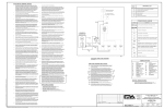
1
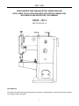
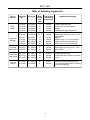
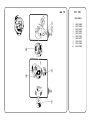
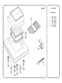
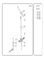
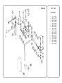
Service manual and parts list
317 - 101
Minerva Boskovice, a.s., Sokolská 60, 680 17 Boskovice, Czech Republic
Member of Dürkopp Adler Group
Tel.: +420-501-453434, 453433, 494111
Fax: +420-501-452165
Edition: 11/2005
Printed in Czech Republic
http://www.minerva-boskovice.com
S735 000038
72317 - 101 I
SINGLE NEEDLE FREE ARM INDUSTRIAL SEWING MACHINE
WITH LOWER OSCILLATING (NON-DROP LIKE) FEED IN COMBINATION
WITH NEEDLE AND UPPER FEED, FOR HEMMING
72317 - 101 I
522 722 730 109 13
Use of Machine
The machine is used for hemming shoe uppers made of natural or artificial leather or of textile. The hemming material
can be leather, textile, and plastic.
1
72317 - 101 I
Specifications
Machine speed
Stitch type
Stitch length
Stitching
Needle
Cotton threads
Synthetic threads
Hook
Presser foot stroke
Thickness of sewn work
Stitching of transition sections
(at reduced speed)
Clear work space
Free arm diameter
Weight of machine head
3,000 stitches per min. at stitch length max. 4 mm
2,500 stitches per min. at stitch length 4 to 6 mm
2,500 stitches per min. with synthetic treads
two-thread lockstitch
0 to 6 mm for textile materials
0 to 4 mm for leather
only forward (for bartacking, a hand lever can be ordered as
Equipment No. 203)
134 R Spec. hard chromium plated, Nos. 90 - 120
123 x 5 Spec., hard chromium plated, Nos. 90 - 120
Schmetz 797 CFCF Nos. 90 - 120
134 LGR, hard chromium plated, Nos. 90 - 120
29.5 tex x 3 - 14.5 tex x 3
PES 25 tex x 1 x 2; 25 tex x 1 x 3
C 235
with hand lever 7.5 mm
with treadle 9 mm
up to 4 mm for leather
up to 6 mm for other materials
for leather sections thickened up to 5 mm, with height difference
of 2 mm
for textile sections thickened up to 8 mm, with height difference
of 2 mm
145 x 100 mm
42 mm
26.5 kg
Technical description
This free arm lockstitch hemming machine is equipped with a rotary hook with horizontal axis, mounted at the end of
the free arm and driven from the lower shaft by a gearing with ratio of 2 to 1, the lower shaft being driven from the upper
shaft by a drive belt with gear ratio of 1 to 1. The stitch length, steplessly adjustable from 0 to 6 mm, is controlled by
a revolving knob situated on the vertical column of the machine arm. The machine is designed for forward stitching but
can be equipped with a hand lever for reverse stitching (bartacking). The presser foot feed movement is derived from an
eccentric mounted on the upper shaft. The drive is transmitted from the electric motor to the upper shaft by a V-belt.
The right-side treadle controls the motor clutch, the left-side one, the presser foot lifting. The principal parts of
mechanisms exposed to increased strain are seated in rolling contact bearings. The machine has a wick group
lubrication and an automatic hook lubrication. Some lubrication places are oiled individually. For reasons of security,
the machine is equipped with a V-belt guard and a thread take-up lever guard.
In its basic version, the machine is supplied without lighting, but is fitted with a screw and washer to receive a suspensiontype lighting, available as Equipment No. 300.
2
72317 - 101 I
Equipments and their Use
Commercial
designation
Ordering No.
317 E 043
S791
317 E 046
S791
see table on page four
Z 066
S791
Z 074
S791
317 Z 109
S722
Z 012
S794
Z 011
S794
124033 35
124046 35
995066
995074
730109 40
222012
222011
Name
Basic hemming set
Stitching set for stitching without hemming equipment
Hemming equipments
Attachment cpl. for hand wheel
Parts for backtacking
High mortality spare parts kit in a plastics box
Halogen lighting (12 V, 20 W - contains transformer)
Suspension-type lighting
3
72317 - 101 I
Table of hemming equipments
Type of
material
Equipment Ordering No.
No.
Width Production No.
of hemming
border
equipments
strip
(mm)
Suitable for hemming
317 N 007
317 N 008
317 N 028
317 N 029
S791 705007
S791 705008
S791 705028
S791 705029
8
10
14
16
049 064
049 253
049 254
049 560
Leather upper with lining
Textile shoes for winter season
Slippers
Leather upper, edge of leg portion
317 N 009
S791 705009
8,5 - 9
049 276
Textile with
selvedge
317 N 011
317 N 024
317 N 012
317 N 013
S791 705011
S791 705024
S791 705012
S791 705013
13
14
16
20
049 301
049 625
049 278
049 302
Textile upper with linning, up to 1.8 mm
thick material
Slippers
Slippers, up to 1.7 mm thick material
Insole, up to 3.8 mm thick material
Insole, up to 2.8 mm thick material
One-sided
folded textile
317 N 014
317 N 015
S791 705014
S791 705015
8
11
049 306
049 307
Textile upper with lining, up to 1.7 mm
thick material
Double-sided
folded textile
317 N 017
317 N 018
317 N 019
S791 705017
S791 705018
S791 705019
21
23
26
049 437
049 308
049 280
Textile upper with lining
Textile shoes winter season, with warm
lining
317 N 022
317 N 026
S791 705022
S791 705026
8
8
049 277
049 626
Leather and textile upper with lining
For inserting binding made of "Chemlon"
(a synthetic material)
Upper
leather
Synthetic
material
4
72317 - 101 I
I.
INSTRUCTIONS FOR SERVICING OF MACHINE
A . General instructions
1.
Read the instructions of the manual carefully and adhere to them.
2.
During transport and while unpacking the machine, proceed in accordance with the instructions and marks on the
packing.
3.
Report any damage which has occured during transport to the railway authorities or to the forwarding agents at
once. Immediately after unpacking, check the contents against the order and report any discrepancies to us. We
cannot recognize claims submitted at a later date.
4.
Having transported the machine to its work site, remove the preserving grease coating and all impurities from the
machine head. make sure that no machine part has become loose and that its mechanism is free of any foreign
body.
5.
Lubricate the machine daily. Before lubrication, always check whether the lubrication places are clean. It is
advisable to lubricate frequently in small quantities rather than conversely. With a hand oil can, drip oil into all the
holes marked in red. Check the oil level on the oil level indicators on the machine arm.
6.
Clean the machine daily, in particular the parts which become choked by impurities from the sewn material.
During the cleaning, carefully check whether no machine part has become loose.
7.
Once a week, during thorough cleaning, carefully check the whole machine to see that no parts are damaged
and that all machine mechanisms operate correctly. Any faults ascertained must be repaired immediately. Once
a year, general overhaul should be carried out. The machine should be dismantled, thoroughly cleaned, individual
pieces as well as the parts of the electrical equipment inspected, faulty or worn out pieces repaired or exchanged.
8.
Adhere to the safety regulations. Never clean the machine or repair defects until the machine is at rest. Do not
remove covers or other safety devices.
9.
The electrical equipment of the machine should be kept in a good and faultless state, in accordance with the
electrotechnical and safety regulations. The lead - in cable, supplied as a part of the machine, has a corss sectio
of 4 x 1 mm2, and must be protected accordingly in each phase. If the machine is provided with a plug make sure
always before plugging in that all switches are off. Never try to repair any defects of the electrical equipment by
ourself but call in an expert electrician.
10. We cannot assume any responsibility for the consequences resulting from the non-observance of these
instructions.
B. Packing, unpacking, cleaning and lubrication of machine
1.
Packing of machine
The machine head is seated in a separate case, the stand either in crating or in another case (for severe climate
conditions).
2.
Unpacking of machine
When taking over the machine from the railway authorities or in the works ascertain whether it has arrived in good
order. Report any damage which has occured during the transport to the railway authorities or to the forwarding
agents immediately. The unpacking should be carried out carefully so as to prevent damage to machine parts.
5
72317 - 101 I
Further check the accessories of the machine against the order and report any discrepancy immediately, as we
cannot consider belated claims.
3.
To set the machine on stand
When unpacking the machine out of the box and when putting it from one place to another, always hold it by its
arm. Remove the protective grease coating and possible impurities and check whether it has no loose parts or
foreign bodies on it or in its mechanism. After the machine has been brought to its work site, set it on the stand
and fasten it with four screws to be inserted from the lower side of the stand plate. Check the treadles for correct
function, i.e., the right-side one for actuating the clutch of the electric motor, the left-side one for lifting the presser
foot, after connecting the tie rod of the left-side treadle with the lifting mechanism. Screw out the two screws,
remove the belt guard, put the V-belt on the motor pulley, mount the belt guard and fix it it with the screws.
4.
To set and fix the machine
The machine is designed as a stable unit with the stand, requiring no fixing to the floor. To make up for possible
unevenness of the floor, use the levelling rubber piece situated on one of the stand legs and adjustable by means
of turning a handwheel also mounted on the leg.
5.
To clean and lubricate the machine (Figs. 1, 1a)
Before putting the unpacked machine into operation, remove the protective grease coating and
clean the machine thoroughly. Suitable oil for the
machine and the hook is the white heavy vaseline
oil with viscosity 50 mm2.s-1 at 20oC. Since the
machine has a group wick lubrication, drop into the
tank of the oil level indicator more oil than is usual in
the individual lubrication of machine parts. The lubrication holes are marked with red circles around
them. Before lubrication, check if the lubrication
holes are clean, and clean them in case of need. It
is advisable to oil the machine several times a day.
The hook is oiled automatically from the oil tank
located in the machine arm. Check the oil level on the
oil level indicator and refill oil in time. The hook and
its mechanisms should be cleaned several times a
day. Remove the fluff with a fine brush, apply some
drops of kerosene to all soiled parts of the hook and
its surrounding mechanism, let the machine run at
high speed, then stop it, wipe off flushed-out dirt, and
oil the hook with its mechanism. This cleaning
should be carried out daily, in particular after the end
of the work shift, in order to prevent dirt from drying
on the hook and its mechanism. Before proceeding
to clean the machine, unthread it and take the hook
bobbin out of the hook. Once a week, clean the
machine thoroughly from all impurities and from
settled oil.
Fig. 1
Lubrication places:
The two principal lubrication places are located on the upper cover of the machine arm. One of them is used to
refill oil in the oil tank twice a week, to one half of the oil level indicator situated on the front part of the macarm.
The other lubrication places are shown in the lubrication chart.
6
72317 - 101 I
Warning !
Before proceeding to clean and lubricate the machine, be sure to switch off the main switch and hold your
feet away from the machine stand treadles in order to avoid accidental machine start by treadle actuation.
Fig. 1a
6.
Amount of oil supplied for hook lubrication
The oil coming by means of a wick prevents the hook hrom getting seized. After the machine has been put into
service, check at regular intervals the oil level in the oil tank disposed on the machine arm.
To observe:
At the resumption of work after a relatively long interval, e.g., at the beginning of the morning shift, it is advisable
first to remove the gathered supefluous oil from the hook, either by letting the machine run idly for a short period
or by producing a few stitches, about 20 cm, on a test material, to prevent the sewn work from getting soiled by
oil.
7
72317 - 101 I
7.
Instalation and gearing lighting with transformer
Gearing of lighting may be performed by a specialist - electrician with the machine unplugged from mains !
The lamp is assembled on the front part of arm by using the peg. The conductor is passed through a hole in the
stand and after unscrewing the cover of the transformer it is plugged to 24 V screws and ensured with fastener.
The cover of the transformer is screwed and the transformer is fastened with added screws o 4 x 25 into pre-drilled
holes in the bottom side of the machine stand. We must make a hole in the motor clamp from the bottom side
and screw the outlet P 16. The conductor is fastened under the installed fasteners and screwed to the transformer
after passing through the outlet P16 and then it is screwed to the 2 bottom screws of the clamp. The cover of the
clamp is screwed again. By using the added fasteners the conductor is fastened to the arm of the machine and
the lamp is adjusted to the suitable position.
Warning !
Avoid any intervention into the electrical equipment of the machine but call in an electrician.
Unqualified intervention ivolves the risk of accident by electric shock.
8.
Hand reverse sewing lever instalation (Fig. 2)
It is possible to assembly the lever for hand controlled bartacking. We unscrew the screws /1/ and put off the cover
of the belt. Then we slack the screw of the cradle /4/ through the hole in the arm. We shift the reverse sewing shaft
towards the worker. By shifting hand lever /2/ we must be careful not to deform the cradle bar /3/. We can check
the assembly by eye after unscrewing the rear cover /5/. We define the axial will of the lever and cradle, we adjust
the lever to the same position as the machine and tight up the screw /4/. We test the sewing and screw up the
cover of the belt. By pressing of the lever down, the sewing direction will be changed. After release the lever returns
to previous position and the machine will sew in front direction.
3
5
4
2
Fig. 2
8
1
72317 - 101 I
C. To prepare the machine for sewing
1.
General inspection
Inspect the machine thoroughly for loose parts as well as for the presence of foreign bodies. With the electric motor
switched off, depress the right-side treadle and rotate the handwheel by hand to see whether it revolves freely and
whether the machine is adjusted correctly. Further check for correct function:
- the presser foot lifting with the left hand and with the left-side treadle
- reverse stitching by means of the hand lever on the vertical column of the machine arm
2.
Sense of rotaion
The correct sense of rotation of the machine handwheel is anticlockwise, viewing the machine from the side of the
handwheel.
3.
Electrical equipment
An electrician connects the machine to the mains 3 x 380 V, 50 Hz. Switch on the electric motor and check
whether the pulley turns in the correct direction shown by the arrow on the cover of the electric motor, i.e., to the
left, toward the operator. If this is not the case, the plug of the lead-in cable must be taken out and the cable must
be switched over on the plug or on the terminal board of the electric motor. The incorrect sense of rotation of the
pulley is inadmissible.
Warning !
Avoid any intervention into the electrical equipment of the machine but call in an electrician.
Unqualified intervention ivolves the risk of accident by electric shock.
4.
V-belt and its tension (Fig. 3)
The V-belt tension can be adjusted by displacing the
electric motor in the groove of its holder after loos-ening
the four clamping screws.
The correct belt tension ensures transmission of full
power with losses reduced to minimum. To check the
tension of the V-belt, depress it lightly in the middle
part between the handwheel and the motor pulley; if the
belt tension is correct, the pressed-on part will yield
some 20 mm sideways. Excessive tension of the Vbelt reduces machine output and increases both the
power consumption and the wear of the bearings. Set
the machine to its opera-tive position, check the V-belt
for correct tension, and mount the belt guard.
Before proceeding to any adjustment on the ma-chine,
be sure that it is switched off.
5.
To lift the presser foot
The lifting and sinking of the presser foot is actuated by
the left-side treadle. To lift the presser foot and to lock
it in the lifted position, the hand lifting lever placed at
the rear side of the machine arm can alsobe used. To
sink the presser foot onto the sewn work, first slightly
depress the left-side treadle so as to disengage the
locking of the lifted presser foot.
9
Fig. 3
72317 - 101 I
6.
Needles and threads
The machine requires the use of needles 134, Schmetz 797 CFCF current sizes, hard chromium plated.
Considering the high machine performance and the resulting needle heating, it is advised to use hard chromium
plated needles. The size of the needle to be used depends on the size of the thread, since it must pass freely
through the needle eye. It is advisable to choose a needle sufficiently big to permit free thread passage through
the needle eye. Only high-class threads should be used, an S-twist one for a the needle, and an Z-twist one for
the hook bobbin. A coarse thread or one which has to overcome considerable resistance when passing through
the needle eye reduces the machine performance and increases its trouble incidence. With synthetic threads, it
is necessary adequately to reduce the sewing speed and to use only hard chromium plated needles to improve
heat dissipation from the area of the needle eye so as to avoid the risk of melting and breaking the synthetic thread.
7.
To insert the needle (Fig. 4)
2
Switch off the motor, depress the right-side
treadle, and rotate the handwheel towards you
until the the bar reaches its top position, i.e., until
the greatest possible distance between the needle holder and the throat plate has been obtained.
Sink the presser foot on the sewn work, loosen
the screw /1/ of the needle bar and insert the
needle up to the stop, with its long groove to the
left of the operator. (The correct insertion of the
needle up to the stop can be visually checked in
the transverse hole of the needle bar). Fix the
correctly inserted needle by retightening the
screw. Each time you inserted a new needle,
check first whether it is straight in order to
ensure that it will pass through the centre of the
needle aperture provided in the feed-dog. Never
use a needle chosen haphazardly but choose it
with respect to the character of sewn work and to
the thread size.
3
5
4
6
Warning !
Before proceeding to exchange the
needle, be sure to switch off the main
switch and hold your feet away from
the machine stand treadles in order to avoid
accidental machine start by treadle actuation.
8.
7
1
To thread the upper thread (Fig. 4)
Put the bobbin on the bobbin stand, unwind a
sufficient portion of it, and pass it through the
Fig. 4
thread guide of the bobbin stand, then through the
thread guides /2/, the adjusting spring, the thread
guide /5/, into the eye of the thread take-up lever, downwards through the thread guide /6/, through the aperture
of the needle bar and, from the left to the right, into the needle eye.
Warning !
Before proceeding to thread the machine, be sure to switch off the main switch and hold
your feet away from the machine stand treadles in order to avoid accidental machine start
by treadle actuation.
10
72317 - 101 I
9.
To take out the hook bobbin
Set the needle bar to its top position, push away the hook cover, open the bobbin case lock, and take the bobbin
case out. As long as the bobbin case lock is open, the bobbin is held in the case. Release the lock, turn the bobbin
case upside down, i.e., with its open side downwards, and the bobbin will fall out.
Warning !
Before proceeding to exchange the bobbin of the hook, be sure to switch off the main switch and hold
your feet away from the machine stand treadles in order to avoid accidental machine start by treadle
actuation.
10. To wind the hook bobbin (Fig. 5)
1
2
3
4
5
Fig. 5
To wind the hook bobbin, a bobbin winder, adapted to be mounted on the front side of the machine arm, is available
on special order as Equipment No. 201. Lead the thread from the bobbin stand through the aperture provided in
the bobbin stand arm, through the aperture of the thread guide /1/ between the braking discs /2/ then through the
other apertures of the thread guide /1/ to the bobbin mounted on the winder shaft, and push the winder shaft. The
winder is now operable and as soon as the machine is started, begins automatically the bobbin winding which the
thread is evenly distributed along the whole of the bobbin width. As soon as the bobbin is fully wound, the stopstart lever springs off and the winder shaft automatically gets out of engagement, thus finishing the winding.
11
72317 - 101 I
11. To thread the lower (Fig. 6)
1
2
Put the fully wound bobbin into the bobbin case and insert the thread end
into the notch of the bobbin case, then pass the thread end under the
pressure spring /1/ of this bobbin case with the bobbin and with released
lock.
12. To catch the lower thread
With your left hand, grasp lightly the upper thread end without stretching
Fig. 6
it. With your right hand, turn the handwheel towards you until the threaded
needle reaches subsequently its bottom and top positions, thereby catching
the lower thread. Draw then lightly the upper thread until the lower thread shows through the aperture of the feeddog, and lay the two thread ends behind the needle. When threaded, the machine may be started only after a
bit of material has been inserted under the presser foot. Both when starting and when finishing the sewing, the
thread take-up lever should be placed in its top position to avoid the risk that the upper thread will thread out and
possibly catch in the hook course.
13. Sewing - the work proper
Insert the material to be sewn under the presser foot and fix it by sinking the presser foot, then switch on the electric
motor and depress gradually the right side treadle. In this way, the machine is set in motion and the sewing
speed increases up to the maximum obtained when the treadle has reached its lowest position. By releasing
the treadle, the clutch of the motor is disengaged, the electric motor braked, and the machine stopped. During the
sewing, avoid pulling the amterial but guide it only. By pulling the material you bend the needle with the risk of
breaking it in case of collisions with the edge of the needle aperture of the feed-dog. Repeated collisions of this
kind make the needle aperture burr which, in its turn, causes thread ruptures. At the end of the sewing operation,
set the thread take-up lever to its top position, raise the presser foot, and take the sewn work from under it. When
observing the described sequence of actions, the machine is ready for next stitching.
To observe:
Having put the new machine in use, do not charge it fully from the very beginning. During the first two or four weeks,
when the machine is running-in, increase its speed gradually from about 2,500 stitches per min. and check carefully
its running. Throughout this time, pay special attention to the machine lubrication. By keeping to these rules you
will obtain a long service life and perfect precision of the machine even at its full performance.
II.
INSTRUCTIONS FOR ADJUSTMENT OF MACHINE MECHANISMS
This section describes adjustments of the type that can be carried out on the work site. Larger adjustments,
requiring more time, should be carried out by a skilled sewing machine mechanician.
1.
Stitch length adjustment (Fig. 5)
The stitch length can be steplessly adjusted from 0 to 6 mm by turning the knob /4/ provided on the vertical part
of the machine arm. By turning it to the right, you increase the stitch length, by turning it to the left, you reduce
it. For easier handling, the reverse stitching hand lever should be slightly pressed downwards during the stitch
length adjustment.
12
72317 - 101 I
2.
Reverse stitching
The reverse stitching is obtained by depressing the hand lever downwards. When released, the lever automatically
resumes its previous position and thus restores the forward stitching.
3.
Thread tension adjustment
(Fig. 7, 7a)
2
The tension of the upper and the lower
thread must be so interrelated that the
stitch binding takes place in the median
layer of the sewn material. To increase
the upper thread tension, turn the nut /1/
to the right (clockwise), to reduce the
tension, turn it to the left. To adjust the
lower thread tension /4 Fig 7a/, use the
screw provided in the middle part of the
pressure spring of the bobbin case. By
turning the screw /5/ to the right /to the
left, you in crease/ reduce the pressure
of the spring on the bobbin case between
which and the spring the thread passes
and, consequently, the lower thread
tension. If the lower thread tension has
been adjusted correctly, the adjustment
of the upper thread tension will be
sufficient, as a rule, to restore the desired quality of stitching.
4.
3
1
To adjust the presser bar pressure
(Fig. 7)
The pressure exerted by the presser
foot is actuated by the adjusting screw
/2/ accessibly located on the upper part
of the machine arm. By turning it to the
right/to the left, you increase/reduce
the pressure. The pressure of the presser
foot must be sufficient to provide for
reliable and continuous feeding even at
the top sewing speed. On the correct
adjustment of the presser bar depends
the uniformity of feeding of the sewn
material as well as that of the stitch
length. Excessive presser foot pressure results in excessive wear of the
whole mechanism and in corresponding reduction in the service life of the
machine.
Fig. 7
4
Fig. 7a
13
5
72317 - 101 I
5.
To adjust vertical stroke of the presser feet (Fig. 8)
The vertical stroke of the presser feet is adjustable so as to meet the feed requirements imposed by various sewn
work thickness, and the vertical stroke of the small feed foot is always greater than that of the big presser foot,
depending on the sewn work thickness and on the width of the tape. To adjust the stroke, loosen the screw /1/
on the lever of the drive shaft and dispalce the lever either toward the operator, to reduce the stroke of the small
presser foot, or away from the operator, to increase it. The stroke of the big presser foot, holding the sewn pushed
to the throat plate, is inversely proportional to that of the small foot, i.e., the greater is the stroke of the small
presser foot, the smaller of the big one. The total stroke range of the presser feet can be adjusted by displacing
the pin of the connecting rod /3/ in the groove of the lever /2/. The lower is the position of the pin with respect to
the pivot axis, the smaller is the total stroke range of the presser feet, and vice versa.
1
2
4
3
Fig. 8
14
72317 - 101 I
6.
Feed-dog (Fig. 9a)
The feed-dog must be properly seated and so fixed with
the screws /1/ as to ensure that the needle passes
through the centre of its needle aperture which must
not be burred, damaged by thread or needle, or otherwise damaged, since any damage of this kind would
unfavourably affect the quality of stitching.
1
Fig. 9a
0,2 - 0,3 mm
7.
To adjust the feed-dog height above the throat
plate (Fig. 9b)
The height of the feed-dog teeth above the throat plate
should be adjusted between 0.2 and 0.3 mm. For
adjustment, first loosen the screw /1/ of the feed-dog
support on the lower arm, then tighten the screw
properly with a screwdriver.
1
Fig. 9b
15
72317 - 101 I
8.
To adjust the movement of the needle and the feed foot
Adjust the eccentric /4/ mounted on the upper shaft, see Fig. 8.
9.
To adjust the needle bar height (Figs. 7
and 10)
The hook must be so interrelated with the
needle that at the moment when the hook
point begins to take up the upper thread
loop, the upper edge of the needle eye
comes to lie about 1.5 mm under the hook
point. If the needle bar height is not adequate to this requirement, loosen the respective screws, remove the front plate,
loosen the scre of the needle bar carrier
/3, Fig. 7/, adjust the needle bar height
correctly, retighten the screw properly, and
mount the front plate.
(1,5)
to 0,1 mm
2
Fig. 10
10. To adjust the hook course (Fig. 10)
Set the stitch length at zero and turn the handwheel towards you until the needle bar reaches its bottom position
and reascends by 2 mm. In this position, the hook point must be aligned with the needle axis, the distance
between the hook point and the needle being 0.1 mm or less. If this is not the case, loosen the hook and set its
position correctly, then retighten the screws and check the gap as well as the hook course.
11. To adjust the hook holder
Set it so as to obtain a gap of about 0.7 to 0.9 mm between the holder lug and the bottom of the groove of the hook
inner part. For this adjustment which is to be carried out only after the hook course adjustment, loosen the hook
holder screws.
16
72317 - 101 I
12. To remove and to mount the drive belt (Fig. 11)
Screw out the screws /1/, remove the upper belt guard /2/, take the V-belt from the handwheel groove, loosen the
two screws, and take the handwheel together with the bearing /3/ from the machine arm and from the upper shaft.
Pass the drive belt /4/ through the aperture thus created in the machine arm, along the upper shaft, and put it on
the two belt wheels. Set the handwheel with its bearing back on the upper shaft in such an angular position that
the first screw in the sense of rotation of the handwheel, when tightened, comes to about on the small flat surface
provided on the upper sahft, then secure the handwheel with screws, mount the V-belt on the handwheel,
mount the upper belt guard and fix it with screws.
3
4
1
2
1
Fig. 11
To observe:
After each mounting or exchange of the drive belt, always adjust the hook course, as described in the preceding
paragraphs of these Instructions.
13. To exchange the presser foot
First raise the needle and, by means of the hand lever, the presser bar, to their top positions, then loosen the
presser foot fixing screw and remove the presser foot. To insert the presser fooot, proceed in the same way. When
the new presser foot is mounted check, in its lifted position, if the needle bar during its reciprocating movement
does not collide with the presser foot.
17
72317 - 101 I
14. To adjust the feed step length
Set the stitch length adjustment knob to its zero position, loosen the screw of the sleeve of the oblique cylinder,
and set the ball bearing with the oblique cylinder in the sleeve so as to obtain zero eccentricity of the eccentric
(visually, the connecting rod remains). Tighten the sleeve screw and check whether the feed step length is the
same for forward and for reverse stitching. If not, readjust it in the above described manner.
15. To adjust the function of the adjusting spring (Fig. 12)
To adjust the tension of the adjusting spring /1/, loosen the
screw /2/ of the thread tensioner bushing /3/ and turn with
screwdriver the pin /4/ of the thread tensioner either to the
right, to increase the tension, or to the left, to reduce it, then
retighten the screw /2/. To set the stroke of theadjusting
spring, loosen the screw of the bushing and turn the
bushing either to the left, to reduce the stroke, or to the
right, to increase it. Retighten the screw and check the
adjusting spring for correct function by producing on a test
material a few stitches. Check also whether the thread, as
it passes around the hook bottom, produces only a slight
movement of the adjusting spring and is not tightened.
1
16. Electrical equipment of machine
3
The machine is driven by asynchronous motor with squirrel
cage mounted on the stand. To reverse the sense of rotation, change-over the lead-in cable either at the plug or
at the terminal board of the motor.
T o o b s e r v e:
Any failure of the electrical equipment should be repaired
by a skilled electrician.
Warning !
Avoid any intervention into the electrical equipment of the machine but call in an electrician.
Unqualified intervention involves the risk of accident by electric shock.
4
5 6
2
Fig. 12
17. To adjust the opening of the upper thread tensioner (Fig. 12)
The opening of the upper thread tensioner is actuated by means of a lever /5/ cooperating with a pin /6/ acting
on a splice plate releasing an extension spring. If the opening fails to function, the whole thread tensioner is to
be pushed some way into the machine, after the loosening of the screw /2/ in the machine arm. The gap between
the thread tensioner discs, when opened, must provide for unobstructed thread passage.
18
72317 - 101 I
18. Assembly and adjustment of the folder (Fig. 12a)
After fixing the folder on the plate by using the two screws bass and nuts it is possible to shift the folder to adjust
required distance from the edge of bind. The distance is smaller by shifting to the left and bigger by shifting to the
right.
By turning aside the folder it is possible to fine adjust the distance between the needle and the folder in ord e r
to create enough space for sewn material.
This adjustment influences accurate leading of the bind to sewn materials.
Binding is the sewin operation which quality depends not only on folder production and sewn material but also on
skilfulness of worker.
That's why we recommend to submit sewing samples and consultation with Minerva workers before the
agreement signature.
Fig. 12a
19
72317 - 101 I
III. MAINTENANCE
1.
Machine cleaning
Plain machine lines help to keep clean outer machine parts. From time to time, it is necessary to remove
waste between the feed-dog and the throat plate. Otherwise, the machine should be cleaned daily.
Warning !
Before proceeding to clean and lubricate the machine, be sure to switch off the main switch and hold
your feet away from the machine stand treadles in order to avoid accidental machine start by treadle
actuation.
2.
General overhaul and repair of machine
It should be carried out once a year. The machine should be set out of operation, cleaned, dismantled, faulty pieces
eschanged and due repairs carried out. The machine should be then assembled and tested. The electric motor
and the electrical equipment of the machine should be inspected and tested. The general overhaul and repair of
the machine should be carried out so thoroughly as to enable the machine to run without major defects for the next
year.
3.
To store the machine
After the machine has been set out of operation, it should be thoroughly cleaned, inspected, and faulty pieces
exchanged, if any. The machine should be then tested, coated with portective grease, and stored with all the tools
and accessories.
20
72317 - 101 I
V. FAULTS AND HOW TO REMOVE THEM
Fault
Cause
a) Heavy machine run.
The machine has been out of use for
considerable time; dried oil and impurities deposited in the bearings.
Inject some drops of kerosene into all
lubrication holes and on the sliding
surfaces and let the machine run
rapidly so as to clean the lubrication
holes in the bearings. Then oil the
machine carefully with sewing machine oil.
b) Slow machine start.
Insufficient belt tension.
Increase the tension by displacing
the electric motor.
c) Upper thread breakage.
1. Slashed thread guides.
1. Ascertain and exchange them.
2. Too sharp hook point.
2. Reapir it.
3. Faulty upper thread guiding or
faulty needle threading.
3. Thread the upper thread correct
(see par. 8, page 10).
4. Incorrect upper thread tension.
4. Adjust it (see par. 3, page 13).
5. Bad needle quality or bent needle.
5. Exchange the needle (see par. 7,
page 10).
6. The thread size is inadequate to
the thickness of sewn material.
6. Use adequate thread.
7. Machine considerably soiled.
7. Unscrew the throat plate, clean
the mechanism, and set the throat
plate.
8. Thread rests wound on the hook.
8. Remove the thread rests.
9. The thread is too thin or not strong
enough.
9. Use adequate thread.
10.Damaged needle aperture of the
feed-dog.
10. Amend or exchange the feeddog.
1. The thread is incorrectly threaded
into the bobbin case.
1. Thread it correctly (see par. 11,
page 12).
2. The thread is too thin or not strong
enough.
2. Use adequate thread.
3. The thread is wound incorrectly
on the bobbin.
3. Wind it on the bobbin correctly.
d) Lower thread breakage.
Remedy
21
72317 - 101 I
Fault
e) Skipped stitches.
f) Needle breakage.
Cause
Remedy
4. Damaged bobbin.
4. Exchange it.
5. Too sharp pressure spring on the
bobbin case.
5. Exchange the spring.
1. Needle inserted incorrectly.
1. Insert it correctly (see par. 7, page
10).
2. Blunt or bent needle.
2. Exchange it (see par. 7, page 10).
3. Slashed or broken hook point.
3. Exchange the hook.
4. Excessive needle aperture in the
feed-dog.
4. Exchange the feed-dog (see par.6,
page 15).
5. Broken adjusting spring for up
per thread tension.
5. Exchange the spring and adjust
the upper thread tension (see par.
15, page 18).
6. Needle bar positioned too high
or too low.
6. Adjust it (see par. 9, page 16).
7. Overturned hook, incorrect hook
course.
7. Adjust the hook course (see par.
10, page 16).
8. Soiled hook mechanism.
8. Clean it with kerosene.
1. Feed-dog positioned too low.
1. Adjust it in height (see par. 7,
page 15).
2. Faulty attendance - pulling the
material.
2. Let the material pass freely.
3. Needle too thin with respect to
sewn work.
3. Exchange the needle (see par. 7,
page 10).
4. Needle inserted incorrectly.
4. Insert it correclty (see par. 7, page
10).
5. Loosened feed-dog.
5. Check and fix it.
6. Excessive upper thread tension.
6. Adjust it (see par. 3, page 13).
22
72317 - 101 I
Fault
g) Heavy and irregular feeding.
h) Stitch forming below sewn material.
i) Stitch forming above sewn material.
Remedy
Cause
1. Feed-dog positioned too low.
1. Adjust it in height (see par. 7,
page 15).
2. Worn-out feed-dog.
2. Exchange it.
3. Insufficient presser foot pressure.
3. Increase the pressure (see par. 4,
page 13).
1. Tensioner discs damaged by upper thread.
1. Exchange them and adjust the
upper thread tension (see par. 3,
page 13).
2. The thread does not pass smoothly
around the hook or catches the
bobbin case.
2. Clean the hook and adjust the
bobbin case.
3. The upper thread is not threaded
between the tensioner discs.
3. Thread it correctly (see par. 8,
page 10).
4. Thread broken and caught between the tensioner discs.
4. Clean the thread tensioner and
adjust it (see par. 3, page 15).
5. Incorrect proportion between the
tensions of upper and lower
threads.
5. Correct the proportion and check
it from time to time (see par. 3,
page 13).
1. Damaged spring on the bobbin
case, the lower thread is braked
insufficiently.
1. Exchange the spring.
2. The lower thread is not threaded
under the spring of the bobbin
case.
2. Thread it correctly.
3. Broken thread caught under the
spring of the bobbin case.
3. Remove the thread.
4. Incorrect proportion between the
tensions of upper and lower
threads.
4. Correct the proportion (see par.
3, page 13).
23
72317 - 101 I
Fault
Cause
Remedy
j) Locked hook.
Thread rests caught in the hook.
Rotate the handwheel in both directions regardless of the considerable
resistance until the caught thread rests
are cut to pieces. Remove them and
start the unthreaded machine. Let it
run for a period, then drip two or three
drops of sewing machine oil on the
hook, and finally check the position of
the overload release clutch.
k) Bad function of hemming equipment.
Correct it (see par. 18, page 19).
V. HOW TO USE THIS CATALOGUE AND ORDER SPARE PARTS
For effective of the Catalogue, carefully study the following information:
The Catalogue is divided into two sections:
1.
2.
Instructions for servicing with figures and technical data
Tables of spare parts with spare part list
Please, specify in each order for spare parts:
a)
b)
c)
machine type and its production No.
the twelve-digit No. of the part
number of parts
24
317 - 101
tab. 1
2
3
4
5
6
7
8
9
10
11
12
13
14
15
16
17
18
19
20
S080
S080
S080
S080
S080
S080
S321
S321
S080
S080
S080
S080
S080
S080
S080
S080
S080
S980
S080
120233
721181
831478
120409
123117
831442
001000
003000
945100
945188
831456
111251
272039
111247
271462
132153
120266
025287
415024
22
23
S080 126069
S311 733620
317 - 101
tab. 2
1
2
3
4
5
6
7
8
9
10
11
12
13
14
15
16
17
18
20
21
22
23
24
S080 123117
S080 313204
S980 041168
S080 161138
S080 945358
S080 945316
S283 002001
ø 3,5/ø 4,8 x 100 mm
S283 002001
ø 3,5/ø 4,8 x 250 mm
S283 002001
ø 3,5/ø 4,8 x 290 mm
S283 002001
ø 3,5/ø 4,8 x 360 mm
S283 002001
ø 3,5/ø 4,8 x 280 mm
S708 130002
ø 2 x 180 mm
S708 130002
ø 2 x 200 mm
S708 130002
ø 2 x 150 mm
S708 130002
ø 2 x 300 mm
S708 130002
ø 2 x 330 mm
S708 130002
ø 2 x 400 mm
S708 130002
ø 2 x 320 mm
S080 111251
S080 421352
S321 001000
S562 411000
S562 260000
317 - 101
tab. 3
1
7
8
9
10
S283 002001
ø 3,5/ø 4,8 x 150 mm
S708 130002
ø 2 x 300 mm
S080 328005
S080 111247
S980 044726
S708 130002
ø 2 x 80 mm
S980 044702
S080 945328
S980 021343
S080 122008
12
13
14
15
16
17
18
19
20
21
22
23
24
25
26
S080
S080
S080
S080
S080
S080
S080
S980
S080
S080
S080
S980
S080
S080
S080
28
S080 120006
32
S283 002001
ø 3,5/ø 4,8 x 90 mm
S708 130002
ø 2 x 150 mm
2
3
4
5
6
33
124050
337043
646137
824367
120296
953191
945077
044907
953052
391158
120530
035501
111238
112015
138009
317 - 101
tab. 4
1
2
3
4
5
6
7
8
9
10
11
12
13
14
15
16
17
18
19
20
21
22
23
24
25
26
27
28
29
30
31
32
33
34
35
36
37
38
S080 349159
S311 000220
S283 002001
ø 3,5/ø 4,8 x 100 mm
S708 130002
ø 2 x 150 mm
S080 630256
S080 112014
S080 328110
S080 384075
S080 120222
S080 825791
S080 263145
S980 035538
S080 318103
S080 141088
S080 413340
S080 152080
S080 120226
S311 733280
S080 338191
S080 141102
S080 627171
S324 512900
S080 613486
S080 630257
S080 570058
S080 111247
S080 814327
S080 122029
S311 733300
S324 060093
S080 120006
S080 120216
S272 032015
S980 045328
S080 511099
S708 130003
ø 3 x 20 mm
S980 045388
S272 225001
10 x 1300 mm
317 - 101
tab. 5
1
2
3
4
5
6
7
8
24
S080 120295
S080 630255
S080 413342
S080 111229
S080 342260
S080 413341
S080 613488
S283 002001
ø 3,5/ø 4,8 x 100 mm
S080 335115
S708 130002
ø 2 x 20 mm
S080 120226
S080 328110
S080 120296
S080 328179
S080 161142
S080 190346
S708 130002
ø 2 x 200 mm
S080 630254
S080 274090
S080 392108
S080 612347
S080 322271
S708 001001
ø 1 x 120 mm
S080 613491
26
27
28
29
S311
S080
S080
S080
9
10
11
12
13
14
15
16
17
18
19
20
21
22
23
733220
630256
338191
112014
317 - 101
tab. 6
1
2
4
5
6
7
8
9
10
11
12
13
14
15
16
17
18
19
20
21
22
23
24
25
S080 120342
S080 271436
S080
S080
S080
S080
S080
S080
S080
S080
S080
S080
S980
S080
S080
S080
S080
S080
S080
S080
S980
S080
S080
S080
111247
410573
392108
136023
615021
839053
120227
623205
274090
274084
044851
120233
613487
384077
131333
152080
263217
120550
048955
825511
120230
190359
317 - 101
tab. 7
1
2
3
4
5
6
7
8
9
10
11
12
13
14
10
16
17
18
20
S080 316101
S080 156040
S080 260497
S980 044853
S283 002001
ø 3,5/ø 4,8 x 90 mm
S708 130002
ø 2 x 150 mm
S080 612347
S080 274090
S080 392108
S080 392106
S080 120296
S080 630254
S080 328179
S080 322271
S708 001001
ø 1 x 120 mm
S080 613491
S080 120410
S980 044907
S708 130002
ø 2 x 20 mm
317 - 101
tab. 8
1
2
3
8
9
10
S980 044907
S080 839291
S708 130002
ø 2 x 100 mm
S080 422218
S080 413331
S708 130002
ø 2 x 200 mm
S283 002001
ø 3,5/ø 4,8 x 100 mm
S080 111247
S080 310270
S080 111227
12
13
S080 120266
S315 264294
15
16
17
18
19
20
S080
S980
S080
S080
S980
S980
4
5
6
7
828079
828080
262074
195041
171037
025244
317 - 101
tab. 9
2
3
4
5
6
7
8
9
10
11
12
13
14
15
16
S080 839291
S708 130002
ø 2 x 100 mm
S080 422218
S080 120226
S708 130002
ø 2 x 200 mm
S080 120425
S080 613486
S080 413340
S708 130002
ø 2 x 150 mm
S080 413331
S080 111247
S080 328110
S080 613492
S708 130002
ø 2 x 20 mm
S283 002001
ø 3,5/ø 4,8 x 100 mm
317 - 101
tab. 10
1
2
3
4
5
6
7
8
9
10
11
12
13
14
15
16
17
18
S980 044822
S080 613490
S080 120295
S080 120246
S080 627171
S080 328110
S708 130003
ø 3 x 20 mm
S080 141102
S080 384075
S080 161142
S080 192061
S080 441187
S980 043029
S080 120218
S080 342258
S080 233051
S080 112013
S080 264326
317 - 101
tab. 11
2
4
5
6
7
8
9
10
11
S080 120014
S080
S080
S080
S980
S080
S080
S080
S080
126110
120226
646162
057011
111247
313301
831443
123117
317 - 101
tab. 12
2
3
4
5
6
7
8
9
10
11
12
13
14
15
16
17
18
19
20
21
22
23
24
25
S080 120014
S080 335114
S080 648109
S080 744409
S080 124050
S080 120059
S080 744410
S080 111247
S080 341218
S080 413335
S080 337087
S080 635175
S080 120230
S708 130002
ø 2 x 90 mm
S080 120071
S080 436035
S708 130002
ø 2 x 80 mm
S080 413333
S080 613493
S080 120226
S080 613492
S080 328110
S708 130002
ø 2 x 20 mm
S080 120457
317 - 101
tab. 13
1
2
3
S080 172014
S080 190614
S980 041270
5
S080 953192
7
8
9
10
11
12
S080
S080
S080
S080
S080
S080
172016
195041
262040
328178
124050
744409
317 - 101
tab. 14
1
2
3
8
5
6
7
8
10
11
12
13
14
15
S080 111229
S080 413343
S708 130002
ø 2 x 330 mm
S283 002001
ø 3,5/ø 4,8 x 290 mm
S080 342259
S080 551154
S080 122007
S080 422213
S080
S080
S080
S080
S272
S980
120216
814327
554093
122029
032015
045504
317 - 101
tab. 15
3
4
5
6
7
8
9
10
11
12
13
15
16
17
18
19
20
21
22
23
S080 120403
S080 647229
S324 840271
S080 111251
S080 413332
S708 002105
ø 1,5 x 120 mm
S080 111247
S080 340164
S080 945323
S080 551155
S311 122007
S080 413334
S283 002001
ø 3,5/ø 4,8 x 280 mm
S708 130002
ø 2 x 320 mm
S080 424051
S283 002001
ø 3,5/ø 4,8 x 250 mm
S708 130002
ø 2 x 300 mm
S080 120226
S080 436355
S080 120006
317 - 101
tab. 16
1
2
5
6
7
8
9
10
S080 635272
S080 120248
S080
S980
S980
S080
S080
S080
331162
057138
048955
120550
190359
120259
317 - 101
tab. 17
1
2
3
4
5
6
7
8
9
S980
S080
S080
S080
S080
S080
S080
S080
S080
035540
945294
316102
825963
190347
161163
123117
941119
120227
317 - 101
tab. 18
1
2
3
4
5
6
7
8
9
10
11
12
13
14
15
16
17
18
19
20
21
22
23
24
25
26
27
28
S980
S080
S080
S080
S321
S080
S311
S080
S080
S080
S080
S323
S311
S311
S080
S980
S080
S080
S324
S080
S080
S311
S980
S980
S080
S080
S080
S080
036097
131163
416135
442336
953200
265037
732014
161137
551047
613179
120252
081210
515095
515089
264243
049501
335108
424075
870000
410641
260378
733181
025249
025249
827194
260510
163106
161138
317 - 101
tab. 19
S522 000235
1
2
3
4
5
6
7
8
9
10
S522
S522
S522
S522
S522
S522
S080
S522
S522
S522
006008
000006
006010
006036
005227
005404
685017
005413
005229
005406
317 - 101
tab. 20
S791 995140 /1
1
2
3
4
5
6
7
S080
S080
S080
S080
S321
S080
S413
141168
190441
836381
953206
953251
826387
100130
317 - 101
tab. 21
S791 995140/2
1
2
3
4
5
6
7
S080
S080
S080
S080
S321
S080
S443
131333
384076
839175
141307
336002
381148
000006
317 - 101
tab. 22
S791 995140/3
3
4
5
6
7
8
9
10
11
12
13
14
15
16
17
18
19
S443
S080
S080
S080
S080
S080
S080
S080
S080
S080
S080
S080
S080
9205
S080
0223
S080
000006
161142
382098
141129
826298
191108
141133
613561
141123
318069
342136
141141
264159
102788
416146
000486
383022
317 - 101
tab. 23
S791 995140/4
1
2
3
4
5
6
7
8
S981
0077
0077
9330
0791
0791
0791
0791
036162
110220
110230
000177
001081
580100
001091
001096
10
0995
340617
2x
2x
2x
317 - 101
tab. 24
S791 995140/5
1
3
4
5
6
7
8
9
10
S413 731023
S548
9081
S080
S413
S413
S562
S080
S980
001000
500010
813481
000500
000400
002000
829796
092220
317 - 101
tab. 25
1
2
3
4
5
6
7
8
9
S980
S080
S321
S315
S522
S522
S273
S080
S522
092235
265037
953200
264294
006010
000006
025410
685017
006008
4x
2x
4x
4x
4x
4x
10 x
4x
317 - 101
tab. 26
317 E 043
S791 124043 35
1
2
3
4
5
S080 667134
S080 667166
134 No. 110 - 11 x
S080 811638
S080 651483
317 - 101
tab. 27
317 E 046
S791 124046 35
1
2
3
4
5
6
S080 667141
S080 667142
134 No. 110 - 11 x
S980 061210
S080 811656
S080 651479
317 - 101
tab. 28
1
317 N 007
S791 705007
S980 049064
1
317 N 008
S791 705008
S980 049253
1
317 N 028
S791 705028
S980 049254
1
317 N 029
S791 705029
S980 049560
1
317 N 009
S791 705009
S980 049276
1
317 N 011
S791 705011
S980 049301
1
317 N 024
S791 705024
S980 049625
1
317 N 012
S791 705012
S980 049278
1
317 N 013
S791 705013
S980 049302
317 - 101
tab. 29
1
317 N 014
S791 705014
S980 049306
1
317 N 015
S791 705015
S980 049307
1
317 N 017
S791 705017
S980 049437
1
317 N 018
S791 705018
S980 049308
1
317 N 019
S791 705019
S980 049280
1
317 N 022
S791 705022
S980 049277
1
317 N 026
S791 705026
S980 049626
317 - 101
tab. 30
Z 066
S791 995066
1
2
S080 511109
S080 120352
317 - 101
tab. 31
Z 074
S791 995074
1
2
3
4
5
6
7
S080
S080
S080
S080
S980
S080
S980
120295
635271
343096
274097
057211
120550
057212
tab. 32
317 - 101
317 Z 109
5x
S080 120014
3x
S080 141088
5x
3x
3x
5x
S080 123117
S080 265037
S080 120530
S080 126110
1x
3x
S080 124050
5x
3x
S522 000006
S080 120410
S080 120342
S080 264243
3x
5x
1x
1x
3x
S080 122029
S315 264294
3x
S522 000235
5x
S522 006008
S522 006010
S980 025244
S722 730109 40
317 - 101
tab. 33
Z 012
S794 222012
1
2
3
4
5
S080
S080
0798
0907
9822
120692
190346
500088
487519
510001
317 - 101
tab. 34
Z 011
S794 222011
1
2
3
4
5
6
7
8
9
10
11
12
13
14
15
16
17
18
19
20
21
22
23
24
25
26
27
28
29
S345
S980
S080
S080
S080
S080
S080
S080
S341
S345
S980
S080
S080
S080
S347
S321
S980
S080
S080
S080
S273
S080
S080
S080
S080
S735
S345
S980
S345
008000
091660
831506
441501
126085
441502
441570
841541
028052
201000
091814
120279
190347
839169
002000
001000
057091
141154
330088
161163
006001
141265
120261
824095
225018
975176
620040
091816
005000 8 x