1
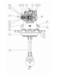
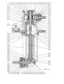
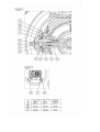
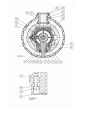
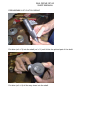
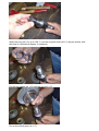
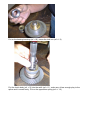
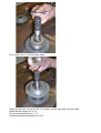
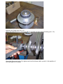
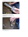
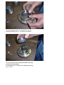
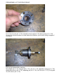
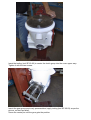
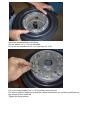
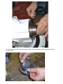
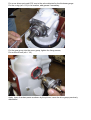
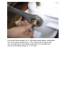
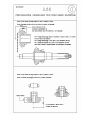
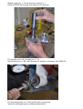
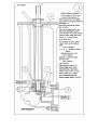
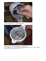
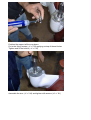
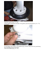
Service
manual
USE OF THE MANUAL
Consignee:
Æ
Æ
Operator
Service
Maintenance
The good functioning and the efficiency of the mechanical components mainly depend on a constant and
correct maintenance.
TAKING VISION OF THE ENTIRE MANUAL allows to properly perform the operations of
ordinary and extraordinary maintenance.
The lack of the recommended operations can compromise the lifetime and the integrity of the transmission
and bring to failure or injury to the operator.
In the event of breakdown or anomaly, the prompt reaction from the specialized personnel will guarantee a
higher lifetime of the assembly, preventing further damage in the years.
GENERAL SAFETY RECOMMENDATIONS
IMPORTANT:
Before starting any operation, read this paragraph carefully.
Safety precautions
The correct use and the correct repair of the assembly and its components are very important for security
and reliability. The recommended procedures, that are listed on this service manual, have been tested as
operative ways to act. Strictly follow each procedure making use both of writings and illustrations.
Some of these procedures show the usage of pertinent tools designed to perform every operation clearly and
correctly.
Some specific tools must be used, where necessary, to perform some proper operations. It is impossible to
manage every working procedure or all the possible methods with their own risks, therefore whoever uses
not recommended tools must be aware that the safety of the operator and the boat will be endangered.
Recall icons
= DANGEROUS OPERATIONS FOR THE SAFETY OF THE OPERATOR
= WEAR PROTECTIVE GLOVES FOR HIGH TEMPERATURE
= OPERATION REQUIRING PARTICULAR ATTENTION AND PRECISION FROM THE
OPERATOR
= OPERATION DAMAGING THE COMPONENT OR PRODUCT IF NOT PERFORMED
CORRECTLY
Repair
The procedure for assembly / disassembly of the transmission allows to perform the complete overhaul of
the group and is assisted with photos, for a complete and safe guide for each operation.
It is assumed that the transmission has been removed from the vessel. The deep knowledge of the assembly
allows the correct estimate of the kind of procedure to be followed, which may only require the disassemble
of a few components, operating on a part of the transmission only.
Recommended tightening torque, based to the screw type
Filettatura
vite
8,8 (8G)
10,9 (10K)
12,9 (12K)
Nm
Nm
Nm
M2
M 2,3
M 2,6
M3
M 3,5
M4
M5
M6
M7
M8
M 10
M 12
M 14
M 16
M 18
M 20
M 22
M 24
M 27
M 30
0,37
0,60
0,86
1.34
2,06
3,04
6,03
10,3
17,16
25,50
50,01
87,28
138,27
210,84
289,3
411,88
558,98
710,99
1049,32
1421,97
0,52
0,84
1,21
1,88
2,89
4,31
8,48
14,71
24,52
35,30
70,61
122,58
194,17
299,1
411,88
578,50
784,54
1000,28
1480,81
2010,38
0,63
1,01
1,45
2,26
3,48
5,15
10,2
17,65
28,44
42,17
85,32
147,10
235,36
357,94
490,34
696,28
941,44
1196,42
1775,01
2402,64
SAIL DRIVE SP 60
SHOP MANUAL
PREASSEMBLY OF CLUTCH GROUP
Put shim (ref. n°3) into the shaft (ref. n°1) until it hits the splined part of the shaft.
Put shim (ref. n°4) all the way down into the shaft.
Warm the ring (ref n°5) up to 120 °C, put the ring into shaft (ref n°1) as per picture, with
the help of a cylindrical stopper if necessary
Put the two cages (ref. n°6) into the ring (ref. n°5)
Put on the clutch gear (ref. n°7)
Put on the bearing housing (ref. n°8), screw the lock nut (ref. n° 9)
Put the clutch body (ref. n°2) into the sahft (ref. n°1), make sure it has enough play to the
spline and it moves freely. Put on the opposition spring (ref. n° 12)
Put on shim (ref. n° 4) all the way down
Warm up ring (ref. n°5) up to 120 °C, position it all the way down into the shaft.
Insert the two cages (ref. n° 6)
Put on the clutch gear (ref. n° 7)
Position the bearing housing (ref. n°8)
Insert and tighten the fixing nut (ref. n°9)
Secure the clutch group in a vise with the proper tool (tool SP 60-01) to avoid to damage
the spline on the shaft, proceed screwing both nuts on the end of the shaft.
Measure the height of the clutch group, the value must be 83.02 mm.
If it is not, increase or decrease the thickness by adding or removing some shims (ref. n°
3)
Remove the fixing nuts (ref. n° 9)
Warm the bearings (ref. n° 10) up to 120 °C, put them on the bearing housing (ref. n° 8)
Screw the fixing nuts (ref. n°9), tighten and rivet the thread with a punch, in the position of
the markings on the thread.
Position the preassembled clutch group with the thrust blocks of the respective bearings
PREASSEMBLY OF THE INPUT GEAR GROUP
Warm up bearing (ref. n°19) up to 120 °C
Put it as per picture all the way down into the
shaft (ref n° 17)
Insert the drag pin of the oil pump (ref. n° 20)
Put in the rotor of the oil pump (ref. n° 21)
Put on O-ring ref. n°18.
Put the bearing bowl (ref. 19 and 22) into the
bearing housing (ref. n° 14) all the way down.
Put on the previously assembled shaft internally
to the bearing housing.
Put bearing (ref. n°22) onto the bearing housing
(ref. n° 23)
Put the bearing all the way down into the
shaft
Insert and tighten the fixing nut (ref. n° 24)
Rivet the thread using a pin to avoid its
unscrewing, in two opposite locations
Put the oil seal (ref. n° 25) in its position, adding
grease in its location to make the assembly
easier.
Position the oil seal with a stopper.
PREASSEMBLY OF THE DRIVE GROUP
Put on the oil seal (ref. n° 29) internally to the support of the drive group (ref. n° 28)
Grease the oil seal location to make easier the insertion, put it down using a stopper if
necessary
End up the preassembly inserting:
Drive shaft (ref. n° 31), stop pin (ref. n° 31), pin ref. n° 33, opposition spring (ref. n° 34),
sliding block drive (ref. n° 35), adjusting pin (ref. n° 36), lock nut (ref. n° 37), O-ring pos.
30, drive lever (ref. n° 39)
PREASSEMBLY OF THE DRIVE COVER GROUP
Put the bearing bowl (ref. n° 10) into the cover group (ref. n°11)
Put on the clutch group previously preassembled
Insert the tooling (tool SP 60-02) to center the clutch group into the cover upper assy.
Tighten it with the two screws.
Inserit the gear group previously preassembled, apply tooling (tool SP 60-03) as per the
picture, on the input shaft.
Screw the centre pin until the gear gets the position
Verify the measurement on the top of the shaft with a depth gauge.
Disassemble tool SP 60-02, remove the gear group, remove the clutch group.
Adjust the bearings, applying a 0,05 mm preload, dividing the shims into equel parts under
the thrust blocks of the bearings (ref. n° 10)
Put the o-rings (ref. n° 45) on their locations of the lower support, apply some grease
Insert the preassembled clutch group.
Put the sleeve (ref. n° 63) into the shaft.
Put in the two membranes ref. n.41 and later ref. n.42.
Put on the lower support (ref. n° 45) as shown by the picture.
Put them in position making sure that the rubber membranes are correctly positioned on
the internal of their locations.
Tighten the fixing screws.
Put the gear group into the cover group, verify the left distance between the gear group
and the case
Put on as shims as to add 0.05 mm to the value detected by the thickness gauge.
Put the o-ring (ref. n°16) in its location, add grease if necessary.
Put the gear group into the cover group, tighten the fixing screws,
Put on the oil seal (ref n° 18)
Apply layer of sealant paste as shown by the picture, insert the drive group previously
assembled
Put in the fixing screws (ref. n° 88) with thread locker, and tighten.
Put on the drive bracket (ref. n° 38), tighten the fixing screws.
Out the bushing for the breather plug into the threaded hole.
Screw the breather plug (ref. n° 53 e 54).
SEAPROP ASSEMBLY – PDF NUMBER 1
ARRANGE GEARS FOR LOW COVER ASSEMBLY
Detect the measurement shown by the drawing and note it on the form.
Assemble the gear on the shaft, and then the internal part of the bearing on the gear.
59.75 = measurement showing the distance of the position of the mounting face from the
generating (where it is needed to position the gear plus or minus 0,05)
36.25 = measurement to detect on each single gear.
To assemble the gear, use induction frequency heater for bearings like STAR 220-Z serial
900601/6.
To assemble the gear, it must be set at 150 °C for 300 seconds.
To assemble the bearing, it must be set at 120 °C for 220 seconds.
NOTE: before to assemble the bearing, wait for the gear to cool down.
Detect the measurement shown by the drawing and write it down on the form or on the
item.
Assemble the bearing on the gear paying attention at the correct position all the way down.
Measurement to be taken: 24.5
51.5 = the measurement defines the real distance from the generating.
ADJUSTMENT OF THE OUTPUT SHAFT
Scheme n° 1
Adjustment position gear Z 22
Assemble tool (1) fixing it with the vertical tension rod.
Assemble the bushing (2) replacing the pilot bearing on the lower cover group.
Temporarily close the support to the lower cover group.
With dial gauge, measure the axial play (C) i.e. 0.26
HOW MUCH TO ADJUST
A + B -59.75 = X
X + C = shims to add
Example
23.49 + 36.25 -59.75 = -0.01
-0.01 + 0.26 = 0.25
WHERE TO ADJUST
Add shims between support and bearing as shown by the *
HOW TO ADJUST
Remove the outer bowl of the bearing from its bearing housing.
Add as many shims as necessary, part number 2013000.
Reassemble the bowl making sure it is in the correct position all the way down.
NOTE: shims must be added in a tolerance range between -0.025 and +0.025
PLAY DETECTED ON A SHAFT WITH DIAL GAUGE C
23.49 = fixed measurement tool A
36.25 = measurement to be detected on each item as B measurement.
Measure gear (ref. n° 74) as shown by scheme n°1.
Insert tool SP60-04 securing it as shown by the scheme.
Put the gear (ref. n°74) on shaft (ref. n° 73).
Insert bearing (ref. n° 82), with the help of a stopper if necessary (tool SP60-05)
Put the bearing bowl (ref. n°82) into the lower cover group.
Insert the output gear group, already preassembled.
Put the bearing bowl (ref. n° 19) into the bearing housing (ref. n° 78).
Insert the support and use the bolts to fix it.
On the end of the shaft, screw the proper tool for bearings adjustment (tool SP60-06).
With a gauge, measure the shifting of the output shaft.
Adjust the bearings adding shims (rif. n° 75 – 81) as shown by scheme n°1.
ADJUSTMENT OF THE VERTICAL TRANSMISSION SHAFT
Scheme n° 3
ADJUSTMENT POSITION GEAR Z 19
First operation is to check the thickness of gear C measurement.
Mount bowl (FAKE 1) of the bearing on the lower cover group and the internal part
(ACTUAL 2) on gear Z 19.
Recall that the gears are coupled.
Place gear / bearing in postion. Couple the gear to the shaft and lock it temporarily with a
nut.
Holding the axis vertically, fit the tooling (3). Then fit tool (4) to put the shaft in line.
With the dial gauge in position *, check play B moving the shaft vertically.
HOW MUCH TO ADJUST
A + B +C – D = shims to add
Example
26.600 + 0.850 + 24.5 – 51.50 = 0.450
WHERE TO ADJUST
Add shims between bearing and case where shown by the #
HOW TO ADJUST
Remove tool n°3.
Remove the temporary nut.
Remove the gear moving the shaft vertically and tooling (4).
Replace the bowl (FAKE 1) with the final one adding the shims for first.
NOTE: The theoretical tolerance with be from 0 to -0.025.
Put the bearing bowl (ref. n° 66) on its location
Detect gear (ref. n° 68) measurement as per scheme n° 3.
Put the bearing (ref. n° 66) on the gear, insert transmission shaft ( rif. n° 60), assemble
the gear and screw the lock nut ( rif. n° 70)
Insert bearing ( rif. n° 62), insert and screw lock nut ( rif. n° 61)
With the proper tool (tool SP60 -07), hold steady the shaft in order to prevent its spin,
screw lock nut ( rif. n° 70) and ( rif. n° 61)
Insert and screw the centering tooling (tool SP60-08) as shown by scheme n° 3
On the end of the shaft, assemble a dial gauge and detect the axial shifting as per scheme
n°3.
Go ahead with the gear adjustment, by adding shims ( rif. n° 67)
Disassemble the adjustment tooling, position the shims, reassemble the components as
shown previously, when reassembling the nut ( rif. n° 70) use drops of thread locker.
Put oil seals (ref. n° 79) in the support (ref. n° 78) as shown by the cross section drawing.
Assemble the O-rings (rif. n° 80) and grease their surface to make their assembly easier.
Position the support all the way down.
Put in the fixing screws ( rif. n° 83) applying a drop of thread locker
Tighten and fit the helicoil ( rif. n° 90)
Assemble the zinc ( rif. n° 84) and tighten with screws ( rif. n° 91)
Manually check the shaft spin and the play between the tapered pairs. There should be no
crawling during the spinning
Put the o-ring ( rif. n° 65) in its location, apply grease to make the assembly easier
Insert the retaining ring ( rif. n° 50)
Join the upper part with the lowe part of the gearbox, place the fixing screws ( rif. n° 72)
and tighten
Put the fitting on the location of the breather plug, screw the fitting all the way, positioning
the chamfered part as per the photo.
Screw the breather plug ( rif. n° 53)
Place the spacers ( rif. n°85) on the output shaft, protecting the splined part applying a
damping layer.
Finish the upper part of the gearbox, applying the oil dipstick and the oil filling plug.
Apply and tighten the lock plug on the membrane( rif. n° 44)
Apply support ( rif. n° 95) and tighten with bolts ( rif. n° 101)
Apply antivibrating bracket ( rif. n° 96 ) and fixing screw ( rif. n° 98), tightening it
Make the adjustment of the drive system..
Put thread locker on the dowel pin ( rif. n° 59). With the drive lever (ref. n° 73) in the
neutral position, manually spin the output axis ( rif. n° 73), screwing the dowel pin (ref. n°
59) at the same time, until you feel like the rotation of the output shaft is resisting. Unscrew
the dowel by ¾ of a revolution and lock it in position with the lock nut.