1
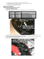
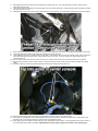
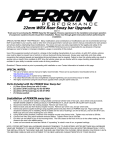
R56 EXHAUST GAS TEMP GAUGE PACKAGE
052009
Thank you for purchasing the ALTA Performance gauge pod. Installation should only be performed by persons experienced in the proper
operation of Mini electrical and body systems. Please read through all the instructions before performing the installation.
SPECIAL NOTES:
•
•
•
•
•
•
•
Use of the factory service manual, can be very helpful during the installation. These can be purchased as the dealership, or online.
http://www.realoem.com has diagrams for the entire car, which can also be helpful.
These instructions are for installing a Prosport EGT Gauge in conjunction with the ALTA gauge pod. There are included instructions with
Prosport Gauges, but we recommend using ours as they are tailored to your Mini.
Included with your Prosport Gauges is extra hardware that will not be used. We recommend using the hardware included with your ALTA
gauge pod, as these are tailored specifically to your Mini.
Gauge fits into gauge pod by using the included foam tape. Use roughly 2” of foam tape (or go about half way around gauge) and
install behind bezel of gauge. When pushing in gauge slightly twist gauge into place. If gauge is not tight enough pull out gauge and
install slightly more foam tape.
It is possible that wires can change colors or function over time. It is very important to use a volt meter to probe for proper voltages
when. A volt meter is something that can be found at a Radioshack or any electronics store.
There is a buzzer that is built into Prosport gauges which is part of the warning system. When you first turn on the gauges this buzzer
will sound off. It can be turned off by pushing button on front of gauge while buzzer is buzzing during startup.
The small buttons on the face of the gauge can rattle slightly. A small bit of silicone, or twisting the bezal slightly will keep it tight.
Installation Instructions
1)
2)
Disconnect battery. Battery is located in boot under lower floor panel.
Remove Exhaust manifold heat shield from engine to expose primaries of exhaust manifold. Locate EGT probe and mark tube
where sensor will fit. Make sure this doesn’t interfere with any other components. If probe is installed facing up (recommended)
take note that a hole will have to be drilled in heat shield to clear wires and harness.
3)
Remove exhaust manifold from vehicle. Once exhaust manifold is removed, pre drill hole in tube with .25” drill bit. Double check this
is the correct placement, and drill hole with 21/64” drill bit.
Once proper size hole is drilled, tap hole with a 1/8NPT tap. NOTE: 1/8NPT is a taper type thread, that seals by the interference
created as the thread gets tightened into the part. Because of this taper it is important when tapping hole, to not tap too deep. We
recommend getting the hole started, and tapping 2 full turns then test if EGT fitting starts to thread. Continue tapping hole 1-2 turns
until EGT fitting threads in 2 full turns by hand. Then tighten fitting one more full turn and fitting should be seated pretty tight. We
also recommend to use Anti-seize on threads of EGT fitting. This helps get fitting tighter into part.
4)
EGT sensor installation shown on R56 model
5)
6)
7)
8)
Reinstall header back into car, making sure to use new exhaust manifold gasket.
If exhaust heat shield is to be installed, drill appropriate size hole in shield to clear wires and probe.
Route EGT probe wire away from any other hot items.
Reconnect battery, and proceed to electrical install.
Electrical Installation
SPECIAL NOTES Regarding Wire Color Codes:
•
•
•
Red wire goes to BATTERY+/12V Constant
Black wire goes to Chassis Ground/-12v
White wire and Orange wire can be varied to produce different gauge colors. (Please follow chart below)
Day Time
(Headlights off)
White
Back-lighting
Red
Back-lighting
White
Back-lighting
Red
Back-lighting
1)
2)
3)
Night time
(Headlights on)
White
Back-lighting
Red
Back-lighting
Red
Back-lighting
White
Back-lighting
Installation
White wire connects to switched 12 volts
Orange wire leave disconnected
White wire leave disconnected
Orange wire connects to switched 12 volts
White wire connects to switched 12 volts
Orange wire connects to illumination power
White wire connects to illumination power
Orange wire connects to switched 12 volts
Remove wipers from car. Locate windshield wipers and remove caps hiding nut, securing wiper to car. Mark window where wipers rest
to ensure that when wipers are reinstalled, they will be in the proper position.
Loosen nuts from wiper roughly 2 turns, and with a rubber or plastic mallet, hit top of nut. This will free up wiper from pivot. Remove nuts
and remove wipers, keeping track of left and right wiper.
Locate and remove 10mm plastic nuts securing plastic wiper panel to car. Remove rubber trim and remove panel from car.
4)
5)
6)
Drill appropriate size hole in plastic wall, and carefully route wires through hole. Run wires toward driver’s side of vehicle as this is
where wires will enter cabin.
Locate wire harness pass through area. Remove plastic cover and expose rubber boot. Using a sharp knife poke small hole into rubber
boot, and push wires through.
Extending wires to reach from sensor to gauge pod inside car may be necessary. Use included wire and electrical connectors to extend.
7)
8)
9)
Remove lower dash panel from driver’s side of car. Remove 4 torx screws from lower panel, and unsnap from upper dash, remove this.
Locate wires that were pushed through firewall, and carefully pull through extra wire.
Locate OBD2 plug and remove screws securing to lower dash. Pull connector down and probe for constant 12volts. This wire should be
a Red wire w/blue stripe and yellow hatch. Using supplied T-Tap, tap into wire. This is the constant 12V wire that will need to be
connected to the red
10) Remove center console to expose final 3 wires to connect to. Locate and remove torx screws located in each of the cup holders.
11) Remove rear cup holder, and raise center console up. Remove E-brake boot from console to allow console to be lifted over E-brake
handle.
12) Lift center console up and unplug cigarette lighter plug and lift console toward passenger side of car.
13) Using supplied T-taps, tap both wires going to cigarette lighter, and tap grey wire going to DSC module.
14) The red wire on cigarette lighter wire is switched power, and brown wire is ground. The Grey w/red stripe wire on DSC module is the
illumination wire. Connect proper wires from gauge pods to wires tapped into above.
15) Install gauge power wire harness to either outer two, (4 pin) receptacles on back of gauge. Connect supplied butt connectors to each of
the 4 wires (Black, Red, Orange, and White). SPECIAL NOTE: If another gauge is going to be installed, used supplied gauge
jumper harness and connect to open 4 pin connecter on gauge to one of the other 4 pin connectors on other gauge. Make sure
you use only the outer 4 pin connectors.
16) Connect supplied wires to gauge power wire harness using supplied butt connectors. Make sure to strip back wire, and match the colors
of the wires to the wires on the gauge power wire harness.
17) Connect Red wire to the constant 12v source (on OBD2 plug), Connect Black wire ground on cigarette lighter harness. Follow the above
chart for orange and white wires.
18) Finally connect sensor wire harness to center of gauge. Make sure that the sensor wire harness gets plugged into the matching gauge.
19) Temporarily connect battery. Test gauges by turning on ignition, make sure gauges illuminate as desired. If gauges are correct, continue
with reinstalling lower dash panel, OBD port and center console.
20) Reinstall window wiper panel taking care to not scratch car when reinstalling. Install plastic nuts removed earlier.
21) Install window wipers back to pivot points. Make sure wipers line up with tape used earlier. Install and tighten nuts to wipers.
22) Continue with installing gauge pod as described above.
23) Continue with test drive to ensure gauges read properly. Temp gauges may take a few minutes to start showing readings depending on
gauge.
24) Hook battery terminals back up.
Peak and Warning Setup
•
•
•
Gauges come with audible alarm turned on. To turn off (which we highly recommend) during power on stage, hold down
peak/warning button.
Gauges have a built in peak reading. This is used by pressing the peak/warning button one time. This will display the gauges’
highest reading. To clear peak reading, hold down peak/warning button for 3 seconds.
Gauges also have built in warning. When the gauges go above this set point they will illuminate the small red light and make
an audible alarm if turned on. To set warning, hold down the Peak/Warning button for 6 seconds. Gauges are now in setting
mode and needle indicates warning setting. To adjust in small increments, push peak/warning button in short bursts. To
adjust more coarsely, push and hold peak/warning button. When setting is adjusted, let gauge sit for 6 seconds to return to
normal mode.
GAUGE TECH
“What should my gauges read” is a common question. While this answers varies greatly we have put together a short description of
what to expect. These are general statements, and the actual reading may vary from car to car.
•
BOOST GAUGE- The boost gauge reads from vacuum to boost. Your Supercharged Mini has an increasing boost curve. This means
that at low RPM boost will be lower than at redline. The stock boost curve is around 8psi-10psi. Cars with 15% reduction pulleys will see
roughly 10-15PSI. This reading can vary with altitude, and with different engine modifications.
•
EGT GAUGE- EGT is Exhaust Gas Temperature. This is a probe that installs into the exhaust system and measures the temperature of
the exhaust. This is a good indication on how hard your engine is working. A properly tuned engine rarely sees above 1500F. When
temps get to 1650F on up, things are getting into the danger zone. This can indicate your engine is running a lean AFR mixture, or
something has gone wrong. When EGTs reach this temp, things can start to melt, like catalytic converters.
•
OIL TEMP- The oil temp gauge reads oil temp by tapping into part of the lubrication system. This reading is also a good way to determine
engine load. Normal temps are around 200 degrees. During track events, or prolonged high speed racing, oil temps can climb to 230+
degrees. Levels above this are considered dangerous as oil viscosity becomes lower. This can cause bearing failure and or premature
wearing of certain components. Oil temp can be used to judge when your engine is up to temp.
•
COOLANT TEMP- While the name is obvious, this gauge is missing from R56 model cars. Normal readings are in the 190-200 degrees.
This is considered Normal Operating Temperature (NOT)
•
OIL PRESSURE- Oil pressure gauges show oil pressure. Oil pressure can vary quite a bit. When the engine is cold the pressure is
much higher than when it is warmed up. This is due to the oil being thicker. When warmed up, oil pressure varies with RPM. At idle the
pressure will be in the 30PSI range. As the RPMs increase, so will pressure. But there is a factory release point around 90psi, which is
reached around 4500 RPM or so.
For questions & comments please contact
[email protected]
503-222-MINI
AIM contact ALTAPERRINSALES