1
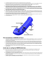
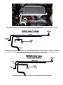
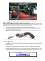
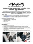
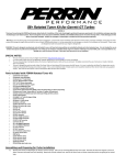
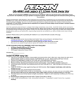
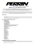
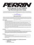
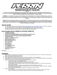
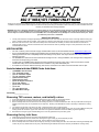
BIG 3” WRX/STI TURBO INLET HOSE
07/08/10
Thank you for purchasing the PERRIN Inlet Hose. Persons experienced in the installation and proper operation of Subaru engines should only perform
installation of this part. Please read through all the instructions before performing the installation. Please make sure you have all hardware and tools
necessary for installation before starting installation.
WARNING: This part is designed, manufactured, and sold solely for use on off-road and racing vehicles not controlled by federal and or local
emissions laws. It is not intended for use on vehicles that operate on public streets and highways. Use of this part on emissions controlled
vehicles may be in violation of federal or local law! ASMC, LTD. is not responsible for any damages as a result of misuse of this part. Check
your local laws prior to use or installation.
IMPORTANT NOTICES!
1.
2.
The Big Turbo Inlet hose is designed specifically for turbos with a 3.125”-2.75” inlet size. Since this hose is much larger than the factory part,
expect clearance issues with the manifold. Take caution as to anything sharp that might cut into the hose, and debure with the correct tool.
Removal of the TGV sensors, TGV motors and butterfly valves in the TGVs are necessary in order to make clearance for inlet hose on
passenger side of motor. Removal of TGVs will cause a CEL that will not cause any damage to engine or hurt performance. CELs can be
removed with ECU reflash.
SPECIAL NOTES:
•
•
•
•
•
The use of a factory service manual is highly recommended. These can be downloaded online at http://techinfo.subaru.com.
Due to the PERRIN inlet hose being larger diameter than the OEM inlet hose, it may touch on the intake manifold and power
steering pressure line. This is completely normal and nothing to worry about. The 3 layer silicone hose is very resistant to
abrasion type wear.
The PERRIN turbo inlet hose has wire reinforcement throughout hose. During installation, if the hose gets bent, simply bend
hose back into shape using your hands.
Included with your PERRIN turbo inlet hose are a few extra fittings, that may not be used. These are included for custom
installs when using catch cans aftermarket boost controllers or any other aftermarket part.
07 models do not need to deal with removing TGV motors, and sensors. The newer cars have them built into one part.
Parts Included with the PERRIN Turbo Inlet Hose:
•
•
•
•
•
•
•
•
•
•
•
•
(1) PERRIN Turbo Inlet Hose
(1) 3” aluminum coupler
(1) 2.75” aluminum coupler
(1) 1.25” aluminum coupler
(1) Size 24 hose clamp
(2) Size 48 hose clamp
(3) 3/8” 90 degree connectors
(2) 1/2”-3/8” reducer
(2) 3/8”-5/16” connectors
(1) 1/2” tee
(13”) 1/2” ID fuel hose
(4) 1/8NPT Brass fittings
Checked By_________________
Removing TGV sensors, motors, and butterfly valves.
1.
2.
3.
4.
5.
6.
Once intake manifold is removed, remove TGV housings from upper casting. (6) 10mm bolts per side.
Each TGV housing has one sensor and one motor. Remove both from each of the housings.
Remove butterfly valves from the inside of the TGV housings by remove 2 screws that hold each valve. Be very careful when removing the
butterfly valve screws, they are very delicate and can strip easy. Grinding of the backside the screws is necessary to alleviate the “locking”
stamp.
Tap shafts out of TGV body, and remove any seal, or bearing that didn’t come out with the shaft.
Drill and tap a 1/8NPT hole in each end of the TGV housings, and plug using supplied 1/8NPT plugs. Note: Do not tap 1/8NPT too deep into
housing as this will not allow for proper seal. Make sure to use grease or antiseize on threads of 1/8NPT plug before tightening.
Reinstall TGV housings to upper manifold making sure to use new gaskets and torque to factory specs.
Removing factory inlet hose.
1.
2.
3.
4.
Follow factory service manual for removal of intake manifold and inlet hose.
Once intake manifold is removed, remove TGV housings from upper casting. (6) 10mm bolts/nuts per side.
Each TGV housing has one sensor and one motor. Remove both from each of the housings.
Remove butterfly valves from inside of TGV housings by removing 2 screws holding each valve. Be careful when removing the butterfly valve
screws, they are very delicate and can strip easy. NOTE: Grinding the backside of screws is necessary to alleviate the “locking” stamp.
5.
6.
7.
8.
9.
10.
11.
12.
13.
14.
15.
16.
Tap shafts out of TGV body, and remove any seal, or bearing that didn’t come out with the shaft.
Drill and tap a 1/8NPT hole in each end of the TGV housings, and plug using supplied 1/8NPT plugs. Note: Do not tap 1/8NPT too deep into
housing as this will not allow for proper seal. Make sure to use grease or antiseize on threads of 1/8NPT plug before tightening.
Reinstall TGV housings to upper manifold making sure to use new gaskets and torque to factory specs.
If aftermarket fuel rails are installed skip to step 10. If OEM fuel rails are installed continue to step 9.
Set manifold on engine, slide inlet hose under manifold and carefully slide onto turbo. (NOTE: A BENT AWL WILL AID IN SLIPPING THE
NEW HOSE OVER TURBO. CAREFUL NOT PUNCTURE HOSE WITH AWL!) Some slight bending of OEM fuel line will be necessary to
clear bottom of inlet hose. Simply push the hard line toward block to add clearance. Check for clearance and adjust before going to step 10.
Put manifold onto engine, but leave loose. Slip PERRIN Big Inlet hose over turbo. (NOTE: A BENT AWL WILL AID IN SLIPPING THE NEW
HOSE OVER TURBO. CAREFUL NOT PUNCTURE HOSE WITH AWL!)
Install aluminum coupler for blow-off valve return hose and connect return hose.
Install manifold to engine using bolts removed earlier, and new gaskets. NOTE: It will be necessary to push manifold into inlet hose in order
to get it to fit. This is where some of the tight clearances are. It helps to have one person push the manifold, while another installs the 8 bolts.
Due to the tight clearances with existing hoses, the BOV return hose will be very tight between the crankcase vent and the black steel pipe for
the crank case vent equalization tubes. Some bending of the black steel vent pipe will be necessary.
See instructions below on hose connections and routing to the PERRIN inlet hose.
Install intake system into inlet hose using either 2.75” or 3” aluminum coupler. Depending on your intake system, the aluminum coupler may
not be necessary to use, and will be loose in 3” inlet hose. Tightening clamp will take up the difference.
Proceed to test drive car.
Hose connections on PERRIN inlet hose
1.
2.
3.
4.
Using the above diagram, install plastic fittings into inlet hose as shown. NOTE: The added fittings in the kit can be used in any
configuration, the above picture is what we feel works best for most cars. Also placement of fittings in hose can be moved
around to suite your needs best.
The forward most spigot goes to boost solenoid return hose. 02-07 cars, this hose comes from passenger side shock tower
where OEM boost solenoid is located. On 08+ STI’s this hose comes from top of intake manifold where solenoid is mounted.
The second spigot connects to the purge control solenoid hose. On 02-07 cars, this hose comes from the small round fitting
connected to front of intake manifold. On 08+ STI, this hose comes from solenoid mounted on front of intake intake manifold
behind power steering pump (also removed earlier during install).
The third spigot connects to crank case vent hose. This hose comes from small piping on front of intercooler, and crosses over
intake manifold.
Crank case re-routing for PERRIN inlet hose
NOTE: Use instructions in conjunction with diagrams below to help with re-routing of 1/2” fuel hose, and bypassing of PCV diagnosis connector.
1.
2.
3.
4.
Remove OEM hose with PCV diagnosis connector from crank case vent fitting located on block next to throttle body.
NOTE:02-03 cars will not have the PCV diagnosis connector.
Install supplied 1/2” fuel hose to crank case vent fitting.
Cut right side valve cover vent hose (leading from cylinder head to steel crossover tube on intercooler) below retaining clip and
install 1/2” tee to bridge both ends of hose. NOTE: The 1/2” tee can be placed anywhere along the rubber hose leading all the
way up to the Inlet hose.
Connect 1/2” hose to open spigot on 1/2” tee installed in step 3. Make sure to route hose away from any moving parts.
(Throttle linkage on 02-05 WRX’s) Trim hose if necessary.
Above diagram showing crank case, and valve cover vent hose routing highlighted in white. Note the “Y” junction on front of
intercooler is actually hard piping, not rubber hose.
Above diagram showing crank case, and valve cover vent hose routing with picture from above removed. Note the “Y” junction on
front of intercooler is actually hard piping, not rubber hose. If you have an 02-03 car, you will not see the PCV diagnosis connector,
but rather a single hose traveling from crank case vent to oem inlet hose.
Above diagram showing crank case, and valve cover vent hose after the hose routing is complete.
The above diagram shows a closeup of the crank case vent/PCV junction. Note: The OEM crank case vent hose is removed in the
picture leaving behind an open fitting. This is where 1/2” fuel hose connects in below steps.
2004+ PCV Diagnosis connector bypass instructions
2004+ vehicles have an additional sensor attached to hose coming from crank case vent going to OEM inlet hose. This sensor makes a
mechanical and electrical connection telling the ECU that a PCV hose is connected and not leaking air. The PERRIN inlet hose requires
bypassing this connector. Again this is not an “active” sensor. The connector only completes a circuit.
1.
2.
3.
Locate PCV Diagnosis connector (grey or white depending on year) on crank case vent hose removed earlier. This was
removed from crankcase vent junction located on the block next to throttle body. (see above picture)
Using below picture, inside PCV Diagnosis connector, find “jumper pin” and remove using needle nose pliers. This pin is
pressed lightly into the electrical side of the connector.
Locate harness and plug that was connected to PCV diagnosis connector, and place “jumper pin” into female pins in the
harness/plug. Use electrical tape to secure in place.
Above diagram showing “Jumper Pin” being removed from PCV diagnosis connecter and crank case vent hose
Common Questions
•
•
•
•
Do I really have to remove my TGVs- No if you are ok with the very very tight clearance between the turbo and TGV sensor and are willing to
fight a little to get it on. We will not warranty any part do to wear in this area if TGVs are left in place. But there is a performance gain from
having the TGVs removed!
My car doesn’t idle or run very well- check that all vacuum connections are connected and routed appropriately. Any leak in these can cause
car to run poorly.
The aluminum coupler is smaller than the ID of the tube- The ID of the 3” inlet hose is 3”. We supply a 2.75” coupler, which makes
connecting the PERRIN intakes and other aftermarket intakes very simple. Even though the coupler is smaller, the silicone hose will clamp
down the .25” difference.
The inlet hose is smashed in to the power steering line- Since the 3” hose is a tight fit, expect some clearance issues with this line. 02 cars
may have issues with clearing do to the older Power steering line being bent differently. Some bending may be necessary in order to better
clear the inlet hose. Loosening this power steering line and rotating it out of the way will help with clearance.
For questions & comments please contact
[email protected]
503-693-1702
AIM contact ALTAPERRINSALES