1
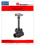
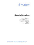
Diverter Ball Valves (DN20, DN25, DN32, DN50) Installation, Operation and Maintenance Manual Reference Number: IOM_007 Date: Bestobell Valves, President Park, President Way, Sheffield, South Yorkshire, S4 7UR Tel: +44 (0) 114 224 0000 Fax: +44 (0) 114 278 4974 [email protected] www.bestobellvalves.com Date of Issue: 04 August 2010 12 August 2010 Issue: Bestobell Valves Inc, 270 Meadowlands Blvd Washington, PA 15301 Tel: +1 724 746 3750 Fax: +1 724 746 0940 [email protected] www.bestobellvalves.com Page 1 of 23 QF 80: Issue 2 A Diverter Ball Valves (DN20, DN25, DN32, DN50) Reference Number: IOM 007 Date: 12 August 2010 Issue: WARNING! BEFORE ANY INSTALLATION AND MAINTENANCE WORK CAN COMMENCE ENSURE THE VALVE AND SURROUNDING SYSTEM IS DRAINED OF PRESSURE AND ISOLATED. Bestobell Valves, President Park, President Way, Sheffield, South Yorkshire, S4 7UR Tel: +44 (0) 114 224 0000 Fax: +44 (0) 114 278 4974 [email protected] www.bestobellvalves.com Date of Issue: 04 August 2010 Bestobell Valves Inc, 270 Meadowlands Blvd Washington, PA 15301 Tel: +1 724 746 3750 Fax: +1 724 746 0940 [email protected] www.bestobellvalves.com Page 2 of 23 QF 80: Issue 2 A Diverter Ball Valves (DN20, DN25, DN32, DN50) Reference Number: IOM 007 Date: 12 August 2010 Issue: Contents Disclaimer ............................................................................................................. 4 Introduction ........................................................................................................... 5 Outline ............................................................................................................... 5 Safety ................................................................................................................ 5 Cleanliness ........................................................................................................ 6 Service Intervals ................................................................................................ 7 Installation ......................................................................................................... 7 Installation Overview ......................................................................................... 7 Preparation ........................................................................................................ 9 Hardware Description ...................................................................................... 10 Installation and Maintenance .............................................................................. 11 Spares Kit ........................................................................................................ 11 Torque Table – Bolted Bonnet......................................................................... 11 Installation Method .......................................................................................... 12 Refit / Refurbishment Method .......................................................................... 15 Troubleshooting .................................................................................................. 21 Contact Details ................................................................................................... 22 Service Record ................................................................................................... 23 Bestobell Valves, President Park, President Way, Sheffield, South Yorkshire, S4 7UR Tel: +44 (0) 114 224 0000 Fax: +44 (0) 114 278 4974 [email protected] www.bestobellvalves.com Date of Issue: 04 August 2010 Bestobell Valves Inc, 270 Meadowlands Blvd Washington, PA 15301 Tel: +1 724 746 3750 Fax: +1 724 746 0940 [email protected] www.bestobellvalves.com Page 3 of 23 QF 80: Issue 2 A Diverter Ball Valves (DN20, DN25, DN32, DN50) Reference Number: IOM 007 Date: 12 August 2010 Issue: Disclaimer PLEASE NOTE: If the valves produced by Bestobell Valves/LNG are refurbished by a third party organisation that is not approved by Bestobell Valves/LNG, then the safety and performance will not be guaranteed and the warranty may be invalid. If unsure about the installation and operation procedures for this valve, please contact Bestobell Valves/LNG. Bestobell Valves has produced this manual in order to provide engineering personnel with sufficient general information to enable the operation, installation and effective maintenance of the valve manufactured by Bestobell Valves. In the interest of product development, the designs and specifications for our products are constantly under review and we therefore reserve the right to make changes and improvements without notice. This manual and the copyright therein are the property of PRESIDENT ENGINEERING GROUP and all information that it contains is confidential. This manual must not be reproduced or disclosed nor must any information taken there from be disclosed, without prior consent in writing of PRESIDENT ENGINEERING GROUP. Bestobell Valves, President Park, President Way, Sheffield, South Yorkshire, S4 7UR Tel: +44 (0) 114 224 0000 Fax: +44 (0) 114 278 4974 [email protected] www.bestobellvalves.com Date of Issue: 04 August 2010 Bestobell Valves Inc, 270 Meadowlands Blvd Washington, PA 15301 Tel: +1 724 746 3750 Fax: +1 724 746 0940 [email protected] www.bestobellvalves.com Page 4 of 23 QF 80: Issue 2 A Diverter Ball Valves (DN20, DN25, DN32, DN50) Reference Number: IOM 007 Date: 12 August 2010 Issue: Introduction Outline This manual is broken down into separate sections: Introduction This section provides information about important safety requirements as well as highlighting the precautions taken at Bestobell Valves to ensure the cleanliness of our products. Details regarding servicing are also introduced. Installation This details the method of installing the valve on site, and includes information on storage, unpacking and inspection. Preparation of the valve and site is also discussed to allow ease of installation and operation. Hardware Description Introduces the product as well as providing a more detailed description including operating conditions and suitable media. Any further requirements for the effective operation of the valve are also discussed. Maintenance Provides information relating to the on-site maintenance of the supplied valve, as well as discussing common problems and solutions. Safety Read and understand these instructions before installing the valve. Improper installation, operation or maintenance by the owner or operator of this valve can result in personal injury. Only use genuine Bestobell Valves spares to ensure safe and optimum performance. Prior to the installation of the valve into the system and any maintenance work, ensure the system is de-pressurised and isolated for the duration of the installation and during any subsequent maintenance. The valve must be installed within a system that has adequate draining and venting provisions. In cryogenic applications the area of pipe-work to receive the valve must be allowed to reach ambient temperature. It is essential that the installers and operators are conversant with all of the safety issues relating to the medium within the system, and are fully trained to an adequate standard. Bestobell Valves, President Park, President Way, Sheffield, South Yorkshire, S4 7UR Tel: +44 (0) 114 224 0000 Fax: +44 (0) 114 278 4974 [email protected] www.bestobellvalves.com Date of Issue: 04 August 2010 Bestobell Valves Inc, 270 Meadowlands Blvd Washington, PA 15301 Tel: +1 724 746 3750 Fax: +1 724 746 0940 [email protected] www.bestobellvalves.com Page 5 of 23 QF 80: Issue 2 A Diverter Ball Valves (DN20, DN25, DN32, DN50) Reference Number: IOM 007 Date: 12 August 2010 Issue: Wear safety glasses and gloves during any installation or operation of the valve. Valves must only be used in a circuit protected by suitable equipment. The valve should be inspected for wear as part of a regular system maintenance programme. Cryogenic burns can occur if the valve is handled during or after the valve has operated. Minor leaks from the outlet side of the valve, if allowed to build up in a confined area, can be hazardous. This can be avoided by dissipating into the atmosphere or a well ventilated area. If valve is to be installed in hazardous climatic conditions or seismic areas, please inform Bestobell Valves Ltd. Identify the intended flow direction and match the valve orientation with its flow direction arrow. Ensure that all end connections to the valve are in line and that the pipe work is supported to reduce unwanted stresses, loading and vibration on the valve and system pipe work. Ensure that all joining materials / components used during the installation of the valve are compatible, and will not cause any deterioration to the valve structure. When using on CO2, the internal atmosphere must be dry and moisture free as any bronze components could be affected by carbonic acid. DO NOT check leaks with hands. Cleanliness Immediately after assembly in a controlled clean room, the valve is sealed in an airtight plastic bag to maintain cleanliness. As such, it is essential to maintain this cleanliness throughout all stages of installation. Particular care should be taken not to contaminate the internals of the valve with grease, moisture, grinding dust, weld/brazing spatter etc. Clean practices will save time later with reduced ‘flushing’ and maintenance. Bestobell Valves, President Park, President Way, Sheffield, South Yorkshire, S4 7UR Tel: +44 (0) 114 224 0000 Fax: +44 (0) 114 278 4974 [email protected] www.bestobellvalves.com Date of Issue: 04 August 2010 Bestobell Valves Inc, 270 Meadowlands Blvd Washington, PA 15301 Tel: +1 724 746 3750 Fax: +1 724 746 0940 [email protected] www.bestobellvalves.com Page 6 of 23 QF 80: Issue 2 A Diverter Ball Valves (DN20, DN25, DN32, DN50) Reference Number: IOM 007 Date: 12 August 2010 Issue: A Service Intervals Bestobell Valves recommends that a major service is carried out on its valves in line with the procedures contained in this manual every 2 years. In addition to this, a regular inspection should take place to ensure correct operational condition. Regular inspections are suggested on a monthly basis and maintenance work should be carried out in line with this service manual. It is recommended that the Service Record Sheet enclosed be fully completed at every service interval. Installation Personnel carrying out Assembly / Joining / Welding / Inspection must be adequately trained and hold the necessary approvals. Ensure that environmental conditions (atmospheric pollution) are compatible with the valve materials. (NOTE: Ensure there is enough space around the valves installed position to allow the removal and refit of the headwork / valve) Installation Overview The quality of performance in service is a function of the care taken to ensure good installation. A careful study of these instructions is therefore recommended, as properly installed equipment will normally operate for long periods without problems. The most critical point in the lifetime of a valve is the time of installation, therefore, proper care at this stage and during any maintenance will increase the probability of trouble free valve service. It is important to maintain cleanliness throughout all stages of the installation, with particular care being taken not to contaminate the internals of the valve with grease, moisture, grinding dust, weld / brazing spatter or other foreign matter. Clean practices will save time later with reduced ‘flushing’ and maintenance. Bestobell Valves, President Park, President Way, Sheffield, South Yorkshire, S4 7UR Tel: +44 (0) 114 224 0000 Fax: +44 (0) 114 278 4974 [email protected] www.bestobellvalves.com Date of Issue: 04 August 2010 Bestobell Valves Inc, 270 Meadowlands Blvd Washington, PA 15301 Tel: +1 724 746 3750 Fax: +1 724 746 0940 [email protected] www.bestobellvalves.com Page 7 of 23 QF 80: Issue 2 Diverter Ball Valves (DN20, DN25, DN32, DN50) Reference Number: IOM 007 Date: 12 August 2010 Issue: STORAGE: The equipment packing cases are NOT waterproof and should be stored in a weatherproof location before use. UNPACKING: It is recommended that before any item is unpacked, it should be moved as close as possible to its installed position. This will minimise the possibility of damage during handling. It is further recommended that each item should only be unpacked immediately before it is required. Before installation the engineer should check for: Damaged Packaging Bent or Distorted Items Scratches, Dents or Damage Particular attention should be paid to the sealing faces on the end connection flanges. TOOLS REQUIRED: No special tooling is required for the installation of this valve. Bestobell Valves, President Park, President Way, Sheffield, South Yorkshire, S4 7UR Tel: +44 (0) 114 224 0000 Fax: +44 (0) 114 278 4974 [email protected] www.bestobellvalves.com Date of Issue: 04 August 2010 Bestobell Valves Inc, 270 Meadowlands Blvd Washington, PA 15301 Tel: +1 724 746 3750 Fax: +1 724 746 0940 [email protected] www.bestobellvalves.com Page 8 of 23 QF 80: Issue 2 A Diverter Ball Valves (DN20, DN25, DN32, DN50) Reference Number: IOM 007 Date: 12 August 2010 Issue: Preparation WARNING! BEFORE ANY INSTALLATION AND MAINTENANCE WORK CAN COMMENCE ENSURE THE VALVE AND SURROUNDING SYSTEM IS DRAINED OF PRESSURE AND ISOLATED. Identify the intended flow direction and match the valve orientation with its flow direction arrow. Ensure that all end connections to the valve are in line and that the pipe work is supported to reduce unwanted stresses, loading and vibration on the valve and system pipe work. Ensure that all joining materials / components used during the installation of the valve are compatible, and will not cause any deterioration to the valve structure. Bestobell Valves, President Park, President Way, Sheffield, South Yorkshire, S4 7UR Tel: +44 (0) 114 224 0000 Fax: +44 (0) 114 278 4974 [email protected] www.bestobellvalves.com Date of Issue: 04 August 2010 Bestobell Valves Inc, 270 Meadowlands Blvd Washington, PA 15301 Tel: +1 724 746 3750 Fax: +1 724 746 0940 [email protected] www.bestobellvalves.com Page 9 of 23 QF 80: Issue 2 A Diverter Ball Valves (DN20, DN25, DN32, DN50) Reference Number: IOM 007 Date: 12 August 2010 Issue: Hardware Description All materials used are selected for their suitability to function at cryogenic temperatures. All valves are degreased for oxygen duty, assembled in clean room conditions, and sealed in robust polythene bags prior to despatch. Maximum Working Pressure: 50 Bar (725psi). Refer to body markings due to end connections down rating the pressure. Temperature Range: +65°C to –196°C or + 150°F to -320°F Only suitable for operation with media: - O2, N2, Ar, CO2, He, Kr, Ne, H2, C2H4, N2O. When using on CO2, the internal atmosphere must be dry and moisture free as bronze could be affected by carbonic acid. It is essential that a cryogenic liquid storage vessel is always protected by a relief valve. If only one relief valve was fitted to the vessel it would be impossible to disconnect for routine maintenance or checking of lifting pressures without risking the safety of the vessel. For this reason, all cryogenic storage tanks require two relief valves to be connected to the tank via a flow diverter valve. This allows one relief valve to remain connected to the vessel whilst the other undergoes maintenance. The Bestobell flow diverter is designed to allow fast changeover between relief valves. It is available in a very wide range of configurations to suit the customer’s requirements. The valve comprises of three main components: 1. The centre body incorporating the inlet port, ball and the operating lever. 2. Two end adaptors incorporating the various outlet ports. It is available in four basic sizes (DN20, DN25, DN32 and DN50) determined by the diameter of the flow passages through the ball. This valve is usually at the hub of a fairly complex piping system and many variations on the basic design have evolved to suit customer’s specific requirements. Bestobell Valves, President Park, President Way, Sheffield, South Yorkshire, S4 7UR Tel: +44 (0) 114 224 0000 Fax: +44 (0) 114 278 4974 [email protected] www.bestobellvalves.com Date of Issue: 04 August 2010 Bestobell Valves Inc, 270 Meadowlands Blvd Washington, PA 15301 Tel: +1 724 746 3750 Fax: +1 724 746 0940 [email protected] www.bestobellvalves.com Page 10 of 23 QF 80: Issue 2 A Diverter Ball Valves (DN20, DN25, DN32, DN50) Reference Number: IOM 007 Date: 12 August 2010 Issue: Installation and Maintenance Spares Kit A D E F C B Reference A B C D E F Valve Size All Sizes Description Gland Ring Washer Seal Cone Seal ‘O’ Ring Gasket Spares Kit Number Contact Bestobell Valves Technical Sales Torque Table – Bolted Bonnet Valve Size DN20 (¾”) DN25 (1”) DN32 (1 1 4 ”) DN50 (2”) Gland Nut Torque 35NM (26 lb.ft) 40NM (30 lb.ft) 40NM (30 lb.ft) 40NM (30 lb.ft) Bolted Cover Nut Torque M10 32NM (24 lb.ft) M12 57 NM (42 lb.ft) M12 57 NM (42 lb.ft) M16 120 NM (90 lb.ft) Apply torques progressively and in sequence. Only use PTFE based lubricants. Torque specified is for lubricated Stainless Steel fasteners. Bestobell Valves, President Park, President Way, Sheffield, South Yorkshire, S4 7UR Tel: +44 (0) 114 224 0000 Fax: +44 (0) 114 278 4974 [email protected] www.bestobellvalves.com Date of Issue: 04 August 2010 Bestobell Valves Inc, 270 Meadowlands Blvd Washington, PA 15301 Tel: +1 724 746 3750 Fax: +1 724 746 0940 [email protected] www.bestobellvalves.com Page 11 of 23 QF 80: Issue 2 A Diverter Ball Valves (DN20, DN25, DN32, DN50) Reference Number: IOM 007 Date: 12 August 2010 Issue: On Cryogenic applications, ONLY use specified Stainless Steel fasteners. Torques specified for valves with PTFE body / bonnet gaskets. Installation Method If the ball diverter is fitted with relief valves and any are removed, the ports are to be blanked off using a suitable plug. If the ball diverter is fitted with relief valves ensure the relief valves are fitted in an upright position and they DO NOT restrict the hand lever. A visual check should be done on the ball diverter unit to make sure that there is always a port in any hand lever position at the inlet, also that there is a port in the direction indicated on the hand lever at the outlets. Ball Diverter valves must NOT be used at the end of a line. STEP 1a (Welded End Connections): Progressively slacken the cover bolts in sequence to preserve the condition of the internal gasket. Remove the valve centre section before installation to protect the internals of the valve from weld/brazing spatter and other particulate contamination. Identify the intended flow direction and ensure that the valve flow direction matches this. Ensure all end connections to the valve are in line and that pipe work is supported to reduce unwanted stresses / loading and vibration on the valve and system pipe work. Ensure that all joining materials / components used during the installation of the valve are compatible and will not cause any deterioration to the valve structure. Bestobell Valves, President Park, President Way, Sheffield, South Yorkshire, S4 7UR Tel: +44 (0) 114 224 0000 Fax: +44 (0) 114 278 4974 [email protected] www.bestobellvalves.com Date of Issue: 04 August 2010 Bestobell Valves Inc, 270 Meadowlands Blvd Washington, PA 15301 Tel: +1 724 746 3750 Fax: +1 724 746 0940 [email protected] www.bestobellvalves.com Page 12 of 23 QF 80: Issue 2 A Diverter Ball Valves (DN20, DN25, DN32, DN50) Reference Number: IOM 007 Date: 12 August 2010 Issue: STEP 1b (Taper Threaded End Connections): For valves with taper threaded end connections a good quality PTFE thread tape may be used. Firstly tighten the end connections by hand to reduce the risk of cross threading before finally tightening with a suitable torque wrench. See torque graph below for female taper threads. MAX TORQUE FOR BSP TAPER ENDS TORQUE (NM) 250 200 150 Torque (NM) 100 50 0 0 10 20 30 40 50 60 VALVE DIAMETER (MM) STEP 1c (Brazed End Connections): If brazing is to be carried out during the installation, the end covers should be removed to avoid any heat damage to the seals. After the brazing of the connections and all necessary cleaning has taken place, the end covers must be carefully replaced. The nuts must be progressively and sequentially tightened to the torque appropriate for the bolt, stud or nut size shown in the torque table on page 11. Bestobell Valves, President Park, President Way, Sheffield, South Yorkshire, S4 7UR Tel: +44 (0) 114 224 0000 Fax: +44 (0) 114 278 4974 [email protected] www.bestobellvalves.com Date of Issue: 04 August 2010 Bestobell Valves Inc, 270 Meadowlands Blvd Washington, PA 15301 Tel: +1 724 746 3750 Fax: +1 724 746 0940 [email protected] www.bestobellvalves.com Page 13 of 23 QF 80: Issue 2 A Diverter Ball Valves (DN20, DN25, DN32, DN50) Reference Number: IOM 007 Date: 12 August 2010 Issue: STEP 2: After completing and checking the welded/brazed end connections, ensure the internal seat surfaces are clean and system pipe work is thoroughly flushed in preparation for re-fitting the centre of the valve. STEP 3: Replace the nuts and bolts and tighten sequentially to the torque shown on page 11, this will ensure that the end connections are pulled down squarely onto the gaskets. Open and close the valve to ensure that the valve operation is smooth. STEP 4 (Testing): Before introducing pressure to the valve, carry out a thorough inspection of all connections: welded and/or threaded. Once pressure is introduced to the valve, a method appropriate to the medium being carried by the system should be employed to test for leaks. Never use hands to test for leaks! Step 5 (Operation): Check that the valve operates correctly and that the lever moves freely through its full 180º travel. Note: If unsure about the installation and operation of this valve please contact Bestobell Valves before you continue. Bestobell Valves, President Park, President Way, Sheffield, South Yorkshire, S4 7UR Tel: +44 (0) 114 224 0000 Fax: +44 (0) 114 278 4974 [email protected] www.bestobellvalves.com Date of Issue: 04 August 2010 Bestobell Valves Inc, 270 Meadowlands Blvd Washington, PA 15301 Tel: +1 724 746 3750 Fax: +1 724 746 0940 [email protected] www.bestobellvalves.com Page 14 of 23 QF 80: Issue 2 A Diverter Ball Valves (DN20, DN25, DN32, DN50) Reference Number: IOM 007 Date: 12 August 2010 Issue: Refit / Refurbishment Method STEP 1: Clamp the diverter in place. Unscrew the nuts from the end of the diverter and store in a safe place. Switch to alternate sides of the valve when unscrewing. Store the nuts in a safe place. STEP 2: Remove the cover from the diverter body and discard the gasket from the main body section. STEP 3: Turn the diverter over and re-clamp it into position. Unscrew the nuts from the remaining side of the diverter and store in a safe location. Switch to alternate sides of the valve when unscrewing. Place the nuts to one side for later use. Remove the cover and discard the gasket. STEP 4: It is recommended that the specialist tool pictured is used to remove the PTFE seals from both of the diverter covers. Discard the PTFE seals. Bestobell Valves, President Park, President Way, Sheffield, South Yorkshire, S4 7UR Tel: +44 (0) 114 224 0000 Fax: +44 (0) 114 278 4974 [email protected] www.bestobellvalves.com Date of Issue: 04 August 2010 Bestobell Valves Inc, 270 Meadowlands Blvd Washington, PA 15301 Tel: +1 724 746 3750 Fax: +1 724 746 0940 [email protected] www.bestobellvalves.com Page 15 of 23 QF 80: Issue 2 A Diverter Ball Valves (DN20, DN25, DN32, DN50) Reference Number: IOM 007 Date: 12 August 2010 Issue: STEP 5: Remove and discard the ‘O’ Ring from both of the diverter covers. STEP 6: Unscrew and remove the screw and washer located over the hand lever. Store the screw in a safe place and discard the washer. STEP 7: Pull the lever off of the diverter stem. STEP 8: Unscrew the gland nut with the appropriate torque wrench. Bestobell Valves, President Park, President Way, Sheffield, South Yorkshire, S4 7UR Tel: +44 (0) 114 224 0000 Fax: +44 (0) 114 278 4974 [email protected] www.bestobellvalves.com Date of Issue: 04 August 2010 Bestobell Valves Inc, 270 Meadowlands Blvd Washington, PA 15301 Tel: +1 724 746 3750 Fax: +1 724 746 0940 [email protected] www.bestobellvalves.com Page 16 of 23 QF 80: Issue 2 A Diverter Ball Valves (DN20, DN25, DN32, DN50) Reference Number: IOM 007 Date: 12 August 2010 Issue: STEP 9: Rotate the stem 90º and the ball can now be pulled from the diverter body. STEP 10: Push the stem down into the diverter body. Pull the stem out of the body. STEP 11: Remove and discard the gland ring. STEP 12: It is recommended that the tool pictured is used to remove the PTFE seals from the diverter gland. Discard the PTFE seals. Bestobell Valves, President Park, President Way, Sheffield, South Yorkshire, S4 7UR Tel: +44 (0) 114 224 0000 Fax: +44 (0) 114 278 4974 [email protected] www.bestobellvalves.com Date of Issue: 04 August 2010 Bestobell Valves Inc, 270 Meadowlands Blvd Washington, PA 15301 Tel: +1 724 746 3750 Fax: +1 724 746 0940 [email protected] www.bestobellvalves.com Page 17 of 23 QF 80: Issue 2 A Diverter Ball Valves (DN20, DN25, DN32, DN50) Reference Number: IOM 007 Date: 12 August 2010 Issue: STEP 13: Starting from inside the diverter body, insert the stem into the hole in the body. Rotate the stem so that the shape of the stem corresponds to the slot on the ball. This should allow the ball to be easily slid back onto the stem. With the ball attached to the stem, rotate the stem 90º to lock the ball in position. STEP 14: Replace the diverter gland seal with the new one from the spares kit. Slide the flat seal from the spares kit down onto the stem. STEP 15: Slide the gland ring from the spares kit down onto the stem. STEP 16: Place the gland screw onto the stem. Loosely tighten the gland screw to hold it in place. DO NOT fully tighten the gland screw at this stage. Bestobell Valves, President Park, President Way, Sheffield, South Yorkshire, S4 7UR Tel: +44 (0) 114 224 0000 Fax: +44 (0) 114 278 4974 [email protected] www.bestobellvalves.com Date of Issue: 04 August 2010 Bestobell Valves Inc, 270 Meadowlands Blvd Washington, PA 15301 Tel: +1 724 746 3750 Fax: +1 724 746 0940 [email protected] www.bestobellvalves.com Page 18 of 23 QF 80: Issue 2 A Diverter Ball Valves (DN20, DN25, DN32, DN50) Reference Number: IOM 007 Date: 12 August 2010 Issue: STEP 17: Place an ‘O’ ring from the spares kit into both of the diverter covers. Then place a cone seal, again from the spares kit, into both of the diverter covers. Both the ‘O’ ring and the cone seal can be found in the spares kit. STEP 18: Place a gasket from the spares kit into the groove on the main diverter body. This should be done on both sides of the diverter body. STEP 19: Rotate the ball so that the smooth face is visible as shown. With the diverter horizontal, place the first cover onto the body, therefore resting the cover onto the smooth surface of the ball. Screw the nuts onto the studs just to hold the cover in place, DO NOT fully tighten at this stage. STEP 20: Keeping the diverter horizontal, rotate the ball so that the smooth surface is visible once again, but this time on the opposite side of the diverter. Place the second cover onto the diverter body, ensuring the correct orientation. Bestobell Valves, President Park, President Way, Sheffield, South Yorkshire, S4 7UR Tel: +44 (0) 114 224 0000 Fax: +44 (0) 114 278 4974 [email protected] www.bestobellvalves.com Date of Issue: 04 August 2010 Bestobell Valves Inc, 270 Meadowlands Blvd Washington, PA 15301 Tel: +1 724 746 3750 Fax: +1 724 746 0940 [email protected] www.bestobellvalves.com Page 19 of 23 QF 80: Issue 2 A Diverter Ball Valves (DN20, DN25, DN32, DN50) Reference Number: IOM 007 Date: 12 August 2010 Issue: STEP 21: Tighten both of the covers to the torques specified on page 11 of this manual. Gradually tighten each nut and frequently switch to opposite corners to ensure an even gasket loading and to prevent the seals getting damaged. STEP 22: Tighten the gland nut to the specified torque. STEP 23: Place the lever back onto the gland screw. Secure the lever to the diverter with the screw removed earlier and a new washer from the spares kit. Tighten to the torque shown on page 11. STEP 24: The diverter is now fully reassembled. Check the valve for correct operation and that the lever moves freely through its full 180º travel. Bestobell Valves, President Park, President Way, Sheffield, South Yorkshire, S4 7UR Tel: +44 (0) 114 224 0000 Fax: +44 (0) 114 278 4974 [email protected] www.bestobellvalves.com Date of Issue: 04 August 2010 Bestobell Valves Inc, 270 Meadowlands Blvd Washington, PA 15301 Tel: +1 724 746 3750 Fax: +1 724 746 0940 [email protected] www.bestobellvalves.com Page 20 of 23 QF 80: Issue 2 A Diverter Ball Valves (DN20, DN25, DN32, DN50) Reference Number: IOM 007 Date: 12 August 2010 Issue: Troubleshooting Symptom: Fault: Bestobell Valves, President Park, President Way, Sheffield, South Yorkshire, S4 7UR Tel: +44 (0) 114 224 0000 Fax: +44 (0) 114 278 4974 [email protected] www.bestobellvalves.com Date of Issue: 04 August 2010 Solution: Bestobell Valves Inc, 270 Meadowlands Blvd Washington, PA 15301 Tel: +1 724 746 3750 Fax: +1 724 746 0940 [email protected] www.bestobellvalves.com Page 21 of 23 QF 80: Issue 2 A Diverter Ball Valves (DN20, DN25, DN32, DN50) Reference Number: IOM 007 Date: 12 August 2010 Issue: Contact Details For further maintenance instructions and spares contact: United Kingdom Enquiries: Bestobell Valves/LNG President Park, President Way, Sheffield, South Yorkshire, S4 7UR, England. Tel: +44(0)114 2240263 Fax: +44(0)114 2784974 Email: [email protected] / [email protected] Web: www.bestobell-lng.com / www.bestobellvalves.com United States Enquiries: Bestobell Valves Inc 270 Meadowlands Blvd, Washington, PA 15301. Tel: +1 724 746 3750 Fax: +1 724 746 0940 Email: [email protected] Web: www.bestobellvalves.com Bestobell Valves, President Park, President Way, Sheffield, South Yorkshire, S4 7UR Tel: +44 (0) 114 224 0000 Fax: +44 (0) 114 278 4974 [email protected] www.bestobellvalves.com Date of Issue: 04 August 2010 Bestobell Valves Inc, 270 Meadowlands Blvd Washington, PA 15301 Tel: +1 724 746 3750 Fax: +1 724 746 0940 [email protected] www.bestobellvalves.com Page 22 of 23 QF 80: Issue 2 A Diverter Ball Valves (DN20, DN25, DN32, DN50) Reference Number: IOM 007 Date: 12 August 2010 Issue: Service Record Valve Tag Number: Date: Bestobell Valves, President Park, President Way, Sheffield, South Yorkshire, S4 7UR Tel: +44 (0) 114 224 0000 Fax: +44 (0) 114 278 4974 [email protected] www.bestobellvalves.com Date of Issue: 04 August 2010 Date: Date: Date: Bestobell Valves Inc, 270 Meadowlands Blvd Washington, PA 15301 Tel: +1 724 746 3750 Fax: +1 724 746 0940 [email protected] www.bestobellvalves.com Page 23 of 23 QF 80: Issue 2 A