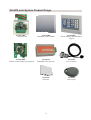
1
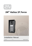
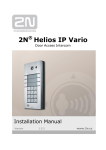
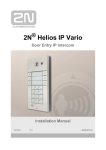
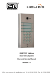
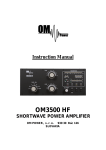
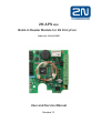
2N APS MINI Build-in Reader Module for 2N EntryCom Order No. 91341612WE User and Service Manual Version 1.1 2N APS mini System Product Range 91341611WE EntryCom Set 9134162WE Standalone reader module 9134167WE Reader module with attendance keypad 91341612WE Build-in reader module for EntryCom 91341631E RS485/Ethernet converter 9134164E PC mini reader 9134165E Chip card 9134166E Chip key fob 2 Introduction Dear customer, congratulations on having purchased 2N APS mini Build-in reader module for EntryCom. We hope that it will fully meet your satisfaction for a long time. As it is a product, which is subject to continuous improvements, we will welcome any comments and improvement suggestions from you. Module Characteristics The reader module is designed for simple access control/attendance registration applications using chip cards. With its design it is suitable to be built in the mechanical part of 2N EntryCom door entry systems, and it therefore allows easy extension of the door entry systems adding the chip card reader function. This module can be built in directly only in door entry systems without numeric keypad. For door entry systems equipped with numeric keypad, use the 2N APS mini EntryCom set module. Brief Description of the System The APS mini system is designed for access control and attendance registration applications in buildings with up to 748 users. It uses contactless chip card and key fob for personal identification. Its benefits include low price, easy installation, high reliability and minimum requirements for operation and maintenance. The basic function of the system, access control and programming of access rights are performed by the reader modules autonomously – without having to be connected to a PC. After having connected the PC, thanks to online status monitoring and archiving of events of the connected reader modules, the system capabilities are extended accordingly. The basic hardware element of the access system of APS mini is the reader module integrating all circuits necessary for one reading point and one door. Operation Modes Autonomous … programming cards are used for programming the access right database (“adding” and “deleting” cards). Offline … a PC is used for programming the access right database; at the same time, it is possible to configure the operation parameters of the reader module. Online … PC continuously communicates with the reader module or a reader module network, as the case may be (up to 32 modules) and archives all events in the system. 2N APS mini reader module is designed for all operation modes. By default it is equipped with 2 programming cards for adding and deleting user cards without having to connect the reader to a PC (autonomous mode). The software controlling the reader module using a PC in the offline and online modes can be downloaded for free at the manufacturer’s website at www.2n.cz. To communicate with the reader modules using a PC it is necessary to install a communication converter RS485/PC (converter RS485/RS232, RS485/USB or RS485/Ethernet) in the communication line. 3 Overview of module functions in the individual operation modes Operation mode autonomous offline online Function Definition of access rights by means of programming cards Signaling of card reading and door lock release Acoustic signaling of an alarm status Change of parameters of operation and alarm statuses Definition of access rights using a PC Reader module status visualization, archiving events in the PC, event tracking and processing Reader output control directly by PC Technical parameters Power Maximum consumption ID technology Maximum number of access cards in memory Input type Output Protective contact (tamper) Typical reading range Communication interface Alternative data output Signaling Operation temperature range Maximum relative humidity 10 ÷ 15 VDC 160 mA EM Marin, 125kHz 748 2, logical, potential-free 1 relay switch contact 2 A / 24 V no 2 cm (in the panel) RS485 galvanically non-isolated WIEGAND (configurable) piezo buzzer + 3 LEDs (on the panel) -25 ÷ +55°C 95%, no condensing Configurable operation parameters Parameter Configurable values Default 7s Acoustic signaling of lock release 0 ÷ 255 s Yes / No Door open delay 0 ÷ 255 s Yes 30 s Time of acoustic signaling of intrusion 0 ÷ 255 s 30 s Time of acoustic signaling of door breaking 0 ÷ 255 s 30 s Time of acoustic signaling of prolonged door opening 0 ÷ 255 s 0s 2nd input function Outgoing button / handle Outgoing button contact Lock release timeout 4 Installation Recommendations The reader module uses for its function a passive RF/ID technology, sensitive to external RF interference. This interference may be caused either by radiation from the surrounding environment or over the power-supply conductors. It is therefore necessary to avoid installation of the modules close to potential sources of electromagnetic field, such as computer monitors (minimum distance 3 m) or various household and industrial appliances. It is also advisable to use the recommended power sources (linear) in order reduce interference coming through the conductors. Interference caused by an external field is the greater the more its frequency approximates the working frequency of the reader modules (125 kHz) and the greater its intensity is. From this point of view, mutual interference of the reader modules is also not negligible – for correct function it is necessary to maintain distance of at least 50 cm. This distance can be adversely affected also by various metallic structures (in case of doubt perform a practical test on site prior to final installation). Correct function and the reading distance can be affected by metal surfaces near the antenna, which cause absorption of the electromagnetic field or mistuning of the module antenna – also in this case we recommend a practical test. Installation of the Module in the Door Entry System Correct installation of the antenna module in the mechanical unit of the door entry system is shown on the picture. Fix the module to the plastic base of the door entry system using the screws supplied. 5 Main Board Description Terminal box Terminal 1 2 3 4 5 6 7 8 9 10 11 12 13 Jumpers Addresses Contact S18.1 ÷ S18.4 S17.7 Meaning Power supply + 10 ÷ 15 VDC Power supply 0 V (earth) Input 1 0V Input 2 Wiegand DATA 1 Wiegand DATA 0 0V A conductor of RS485 line B conductor of RS485 line NC relay contact C relay contact NO relay contact Contact J4 Meaning HW address (see the table on the following page) J5 J6 Meaning RS485 idle state definition (wire A) Termination of RS485 line RS485 idle state definition (wire B) Main Board Connection with the Lock and Door Contacts The relay contact used for door lock switching is led to the terminal box. Use contacts “C” and “NO” for standard locks that will unlock upon voltage presence. Contacts “C” and “NC” are to be used for locks that unlock upon voltage absence but remain locked when voltage is present. Carry voltage from the power supply source to the door lock through these contacts. If your door is equipped with a contact that is activated when the door is closed carry its contacts to input 1 terminal. The contact for door status monitoring (input 1) is taken into account after the first change of status after the module is switched on. If this contact is not occupied the relay for the lock will time always the entire time set, and the “Door Break-In” and “Door open too long” alarms are not generated. The input 2 function can be set for the outgoing button or the door handle contact. The outgoing button is used for the “knob-knob” door configuration for opening the door from the inside (upon leaving the building). The door handle contact is used for “knob-handle” door configuration. 6 Main Board Connection with the Data Bus RS485 You can connect an RS485 data line to the module terminal box. Up to 32 APS mini reader modules can be connected to this data line consisting of three wires. Each module on the bus needs to have a different address assigned by inserting jumpers on the contacts S18 and S17. The address of the module is specified in the following table: Jumper 1 2 3 4 5 HW adress of the module 6 7 8 9 10 11 12 13 14 15 16 21 HW adress of the module 22 23 24 25 26 27 28 29 30 31 32 X18.1 X18.2 X18.3 X18.4 X17.1 Jumper 17 18 19 20 X18.1 X18.2 X18.3 X18.4 X17.1 Sign in the table means jumper inserted on the connection. After changing an address it is necessary to reset the module (disconnect and re-connect the power supply)! Use only the data transmission cables for the data bus (shielded cables or twisted pairs). In the module at the end of the data bus (the last module on the line) it is necessary to attach a terminating resistor by inserting a jumper on the contacts of the J5 jumper. When using some converters, isolators and repeaters on the RS485 bus it may be necessary to install jumpers on connecting pieces J4 and J6, which define the idle state on the bus. If using the converter supplied by the manufacturer (GNOME485) it is not necessary to install jumpers on these connecting pieces. Main Board Power Supply It is convenient to use the door entry system power source for the main board power supply. The only requirement is that this power source has power reserve for the power supply of the reader module (160mA) and the door lock (depending on the type). Rated voltage of the power source must be in the range 10 ÷ 15V DC. If the existing power source does not meet these requirements it is necessary to install a new power supply for the reader. Meaning of the Indication LEDs LED color Red Mode On permanently Flashing in 1s intervals Fast alternation with green Meaning online communication over RS 485 offline operation Address setting mode ID media reading Programming mode Yellow Green 7 Setup of Parameters and Access Rights using a PC The APS mini Reader setup program is designed for operating systems Windows 95, Windows NT 4.0 and higher versions; it does not require installation. It is designed for offline mode of the readers and allows for programming of operation parameters on the individual 2N APS mini modules connected on the data bus RS485. It cannot be used for access right programming. To connect the modules to a PC you need either RS485/RS232 (or alternatively RS485/USB) communication converter with automatic switching of the direction of communication or an RS485/Ethernet converter with the following settings: 8 data bits, even parity, 19 200 bps and 1 stop bit. The main menu of the program includes the following commands: • Program Setup … displays the screen for setup of the PC communication port and the service card code, • Start / Stop … PC-module communication control, • Write … writes the configuration of the general properties in the reader module, • Program End … ends the program. The program desktop is divided into 3 parts: • The area for the reader module status visualization (used for verification of the correct connection of the module). • Area for HW address setup, • Area with controls for the setup of general properties of the module. The following indicators are located in the status line (from the left): • PC-module communication status (red color indicates communication communication without errors is indicated by green color), • Operation parameters writing progress, • Verbal description of the communication status. errors, The operation parameters entered in the corresponding input fields will be set up during communication after pressing the “Write” button. The setup program always communicates with one module (module with the address entered in the “HW Address” field). The progress of the writing is shown by the progress indicator in the second part of the status line. The APS mini Administrator, APS mini Events and APS mini.ED programs are designed for using 2N APS mini in the online mode. In addition to the module parameter programming they allow the user to set the access rights and monitor the different events (e.g., arrivals and departures of persons) and to analyze them. The programs can be downloaded from the manufacturer’s website at www.2n.cz. 8 Setup of Access Rights Using Programming Cards The access rights of 2N APS mini reader modules can be programmed without the use of a PC, thanks to two programming cards that are supplied together with the module. Adding cards to the memory Step 1 Step 2 Step 3 Apply the programming card for adding; the reader will switch into the programming mode. Apply sequentially all the cards that are to have the access right at the particular place. The reader switches automatically back into normal operation mode approximately 15 seconds after the last card is applied. Deleting cards from the memory Step 1 Step 2 Step 3 Apply the programming card for deleting; the reader will switch into the programming mode. Apply sequentially the cards whose access right at the particular place is to be removed. The reader switches automatically back into normal operation mode approximately 15 seconds after the last card is deleted. Deleting all programmed cards Step 1 Step 2 Step 3 5x Apply the programming card for deleting; the reader will switch into the programming mode. Apply the programming card for deleting five times; the reader will delete the contents of the memory of the cards. 9 The reader switches automatically back into normal operation mode. 2N TELEKOMUNIKACE a.s. Mod anská 621, 143 01 Praha 4, Czech Republic tel.: +420 261 301 111, fax: +420 261 301 999, e-mail: [email protected] www.2n.cz 2008, 2N TELEKOMUNIKACE a.s. - Praha OV 1466 v.1.1