1
ATEUS ® - APS MINI
STANDALONE READER MODULE
Order No. 9134162E
User and Service Manual
Version 1.0
Introduction
Dear customer, let us congratulate you on having purchased the ATEUS ® - APS mini
Standalone Reader Module. We hope that this product will make you happy for a long
time. Since it is a brand new product, which is subject to steady improvements, we will be
pleased to hear your comments and recommendations if any.
Module Characteristics
The ATEUS ® - APS mini chip card reading module is designed for simple personnel
access/entry and attendance control applications using chip cards. It is composed of a
main board and reading antenna for contactless chip card code reading. The antenna has
a standard form of a blank key module for the ATEUS ® - EntryCom door communicator
and so it is easy to install it into the door communicator and extend the same with an
ATEUS ® - APS mini module.
Operation Modes
Autonomous … programming cards are used for programming the access right
database ("adding“ and "deleting“ cards).
Offline … a PC is used for programming the access right database and setting the
reading module/reader operation parameters.
Online … the PC communicates continuously with one reading module or a reading
module network (up to 16 modules) and stores all system events into the archives.
ATEUS ® - APS mini is designed for all operation modes. By default, it is equipped with 2
programming cards for adding and removing user rights without the need to interconnect
the reader and the PC (autonomous mode).
The PC-based reader controlling software in the offline and online modes can easily be
downloaded from www.2n.cz, the Technical support Download section. You can also
download related user manuals from here. To communicate with the reading modules
using your PC, install an RS485/RS232, RS485/USB or RS485/Ethernet communication
converter to the communication line.
2
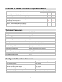
Overview of Module Functions in Operation Modes
Operation Mode
Autonomous Offline Online
Function
Access right defining by programming cards
Card reading and door lock release signalling
Acoustic alarm status signalling
Change of operation and alarm status parameters
Access right defining by a PC
Reading module status visualisation, event storing in PC
archives, event tracking and processing
Reader output control directly by PC
Technical Parameters
Dimensions
Weight
Power supply
Max. supply current
ID technology
Max. count of access cards per memory
Input type
Output arrangement
Tamper-protecting contact
Max. reading radius
Communication channel
Signalling
Operation temperature range
Max. relative humidity
Installation cable length
90 x 55 x 25 mm
0.25 kg
10 ÷ 15 VDC
150 mA
EM Marin
500
2, logic level, potential-less
relay, 1C contact, 2 A / 24 V
optoelectronic
typically 8 cm with ISO chip card
RS485, galvanically non-isolated
3x LED + piezo buzzer
-25 ÷ +50°C
max. 93%, non condensing
1.5 m
Configurable Operation Parameters
Parameter
Values to be programmed
Lock release timeout
2 ÷ 255 s
Door ajar delay
2 ÷ 255 s
Acoustic signalling time - tamper
2 ÷ 255 s
Acoustic signalling time - door breaking
2 ÷ 255 s
Acoustic signalling time - door ajar
2 ÷ 255 s
Second input function
outgoing button / handle contact
3
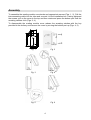
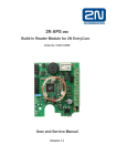
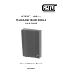
Assembly
To assemble the reading module use dowels and appropriate screws (Figs. 1, 2). Pull the
interconnecting cable into the tube and connect it to the installation box. Having tightened
the screws, put on the cover to the top and then rotate and press the bottom part until the
arresting catches click (Figs. 3, 4).
To disassemble the reading module cover release the arresting catches with the key
provided in the delivery and remove the cover by moving the bottom part up (Figs. 4, 5).
47
23,5
15
7,5
8,5
Ø4
90
82
74,5
Ø5
Ø4
55
Fig. 1
Fig. 2
Fig. 3
Fig. 4
Fig. 5
Fig. 6
4
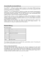
Assembly Recommendations
The ATEUS ® - APS mini reading module is based on the passive RF/ID technology
sensitive to external RF interference. This interference can be either radiated from the
surrounding environment or conducted.
Therefore, it is not recommended to install the modules near potential electromagnetic
field sources, such as PC monitors (within the distance of up to 3 m) or various household
and industrial electrical appliances. You are also advised to use recommended power
supplies (linear) in order to minimise conducted interference.
From this point of view, it is also necessary to consider mutual interference of reading
modules - keep the minimum inter-module distance of 50 cm. This distance can also be
affected negatively by adjacent metallic structures (in case of doubts, perform a practical
on-site test before assembling).
Metal surfaces near the antenna may absorb the electromagnetic field or detune the
module antenna and thus impair the proper function and reading distance – we
recommend you to carry out a practical test in this case too.
Module Wiring
Wire description
Colour
Red
Blue
Black
White
Green
Yellow
Gray
Orange
Brown
Violet
Meaning
+12 VDC power supply
0V
RS485 line A conductor
RS485 line B conductor
RS485 line shield
Input 1
Input 2
NC relay contact
C relay contact
NO relay contact
The reading module inputs must be controlled by a potentialless contact. Connecting the
input to 0V is considered the active status.
Power supply interconnection
The door communicator power supply can be used for supplying the main board
advantageously. The only condition is that this power supply should have a power reserve
for feeding the reader module (150mA) and door lock (depending on the type). The rated
voltage of the power supply must be 10 ÷ 15V dc. If the existing power supply fails to
comply with these conditions, install a new one for the reader.
5
Door lock/contacts interconnection
The relay contacts are used for door lock switching. Use contacts "C“ and "NO“ for
standard locks which unlock by the presence of voltage, and contacts "C“ and "NC“ for
locks that get unlocked in the case of voltage failure and keep locked while voltage is
present. Carry voltage from the power supply through these contacts to the door lock.
If you have a contact on the door that gets activated with the door open, carry the contacts
to input 1 and 0V (yellow and blue wire). If you do not have this type of contact on your
door, interconnect the input 1 and 0V wires. Without this interconnection the door lock
would unlock only for approximately 0.5 s because non-activated door switch terminals
would report an open door.
The input 2 function can be set for the outgoing button or handle contact. The outgoing
button is used in the "knob-knob" door mode for opening the door to a person coming from
the interior (leaving the building). The handle contact is used in the "knob-handle" door
mode. If you do not have the handle contact on your door installed and the door contact is
activated on input 1, interconnect the input 2 and 0V wires and set the input 2 function at
the "handle contact". By doing so you avoid the "broken door" alarm message when the
door is handle-opened from the inside.
RS485 data bus interconnection
You can connect an RS485 data line to the A, B and 0V wires. Up to 16 ATEUS
mini reading modules can be connected to this three-wire line.
®
- APS
Use data transmission cables only for the data bus (shielded cables or twisted pairs). In
the last data bus module (last line module), attach the terminating resistor by inserting a
shorting jumper onto contacts S20.
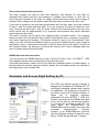
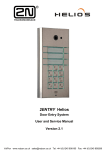
Parameter and Access Right Setting by PC
The APS mini Reader setting software is
designed for Windows 95, Windows NT 4.0
and higher operating systems and requires
no installation. The program is intended for
the offline mode of the reading modules. It
allows
you
to
program
operation
®
parameters for every ATEUS - APS mini
module connected to the RS485 data bus.
It can not be used for access right setting.
To connect the modules to your PC you
need either an RS485/RS232 (or
RS485/USB) communication converter with
automatic
communication
direction
reversal, or an RS485/Ethernet converter
with the following settings: 8 data bits, even
parity, 19,200 bits per second, 1 stop bit.
6
The main program menu contains the following commands:
• Program Setting … displays settings of the PC COM port and service card code;
• Start / Stop … PC- module communication control;
• Write …writes the general parameters to be configured into the reading module;
• Program End/Quit … program end.
The program window is divided into three parts as follows:
• Reading module status visualisation (check of the module wiring correctness);
• HW address setting;
• Controls for general module settings.
The following indicators are located in the status line (from the left):
• PC - module communication status (red = communication errors, green = no errors);
• Operation parameter setting progress;
• Verbal description of the communication status.
HW address setting
The HW address of reading modules is 1 by default. To connect multiple reading modules
to the communication line, set a unique address for each of them. To set the address via
the communication line from your PC take the following steps:
• Connect the module(s) to the communication line;
• Enter the required address into the "HW address“ input field;
• Press the "Set by card“ key to make the program send an address setting command;
the module then waits for about 25s for request confirmation by service card reading
(the service card may be any card whose code has been entered in the "Service card"
field in the program setting menu), this waiting process is indicated by a quick double
flash of the red LED in the interval of approximately 2s;
• Once the service card has been read, the program starts communicating normally with
the reader.
Operation parameter setting
To set the operation parameters entered in the corresponding input fields of the program,
press the "Write" key during communication. The process of writing is indicated by the
progress indicator in the second part of the status line.
The APS mini Administrator, APS mini Events a APS mini.ED programs are designed for
the use of ATEUS ® - APS mini modules in the online mode. In addition to module
parameters programming, they allow the user to set up the access rights and to monitor
and analyse relevant events (e.g. arrivals and departures of persons). You can download
the first two programs including user manuals free of charge from www.2n.cz, Technical
Support Download, the third program can be purchased.
7
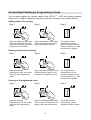
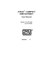
Access Right Setting by Programming Cards
You can also program the access rights of the ATEUS ® - APS mini reading modules
without a PC, using two programming cards, which are included in the module delivery.
Adding cards to the memory
Step 1
Step 2
Step 3
Apply the adding programming
card; the reader goes into the
programming mode (the yellow
LED glows in this mode).
Apply sequentially all cards that
are to be assigned the access
right in the particular place.
The reader transits
automatically into the
standard operation mode
in approximately 15 s after
the last card is applied.
Deleting cards from the memory
Step 1
Step 2
Step 3
Apply the deleting
programming card; the reader
goes into the programming
mode.
Apply sequentially all cards from
which the access right is to be
removed in the particular place.
The reader transits
automatically into the
standard operation mode
in approximately 15 s after
the last card is applied.
Clearing of all programmed cards
Step 1
Step 2
Step 3
5x
Apply the deleting
programming card; the reader
goes into the programming
mode
Apply the deleting programming
card 5 times in a sequence; the
reader clears the card memory.
8
The reader transits
automatically into the
standard operation mode.
2N TELEKOMUNIKACE a.s.
Modřanská 621, 143 01 Praha 4, Czech Republic
tel.: +420 261 301 111, fax: +420 261 301 999,
e-mail: [email protected],
www.2n.cz
2005, 2N TELEKOMUNIKACE a.s. - Praha OV 1195 v.1