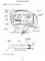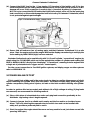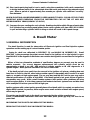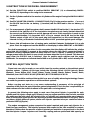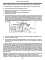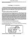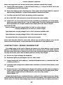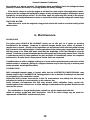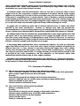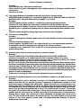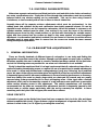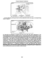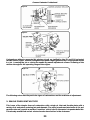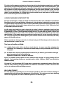
1
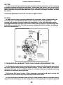
GASTESTER
PROFESSIONAL
Exhaust CO Gas & Engine Analyser
FAULT CODE READER OBD11
COLORTUNE
GASTESTER
EEZIBLEED
PART NO G4121
HANDBOOK
Gunson Gastester Professional
2
Gunson Gastester Professional
SAFETY WARNING
Engine exhaust gas is VERY POISONOUS. Do not carry out work on a car indoors or in a
confined space with the engine running. Ensure that the car is outdoors, and with free ventilation
of fresh air. Avoid breathing exhaust gas while using Gastester Professional in the region of the
exhaust pipe.
DO NOT work on an engine while wearing loose clothing, or with long hair not tied up. Keep
hands, clothing, instrument leads and connectors in a safe position, clear of moving parts (fan,
rotating pulleys and fanbelt), clear of excessively hot parts (exhaust manifold, exhaust pipe), and
HT voltages (spark plugs, and any ignition parts which may produce a high tension spark). HT
VOLTAGES from ignition systems are DANGEROUS. Though unlikely in themselves to cause
permanent injury to a HEALTHY person, they are likely to cause involuntary movement which IS
dangerous when in proximity to an engine compartment.
WARNING. Take care not to short circuit (connect directly together) vehicle powered leads
and earthed leads/metal. (note: including leads switched between these voltages). High currents
may result in damaged or burnt components.
IMPORTANT OPERATING NOTES
This instrument should be allowed to warm up for an absolute minimum of 10 minutes, a
reasonably accurate spot check of CO level is then possible. However, to maintain accuracy
during more prolonged testing/adjustment, allow a longer warm up e.g. 20 -30 minutes so that
setting drift is reduced to a minimum, and check the 2% setting in air 10 minutes after probe
removal (see main instructions).
Warm up the instrument in the same location/position as it is to be used.
IMPORTANT: DO NOT DISTURB THE INSTRUMENT POSITION AFTER SETTING TO 2.0%
The instrument displays two decimal places on the CO range as a result of the high resolution
display. The last decimal place is insignificant and when setting to 2% in air the user should not be
concerned if 2.00% exactly can not be obtained.
SENSOR LIFE:To prolong sensor life allow a period of 10 minutes in air (power on) after use and
avoid excessively rich mixtures. With frequent/heavy commercial use the sensor may become
contaminated within less than one year. (Note: M.O.T. class infra red analysers with extensive
filtration require calibration up to four times annually.) Increasing difficulty in obtaining 2.0%
setting in air, with the adjustment becoming offset, is one clear indication of the need for sensor
replacement.
INSTRUMENT CIRCUIT PROTECTION
Gastester Professional circuitry is fully protected against incorrect connection and can be
subjected to car battery voltages and the instantaneous peaks found in ignition (low tension),
injection and control systems.The high impedance of the BLUE pickup lead ensures that it can not
damage the circuitry being tested.
3
Gunson Gastester Professional
4
Gunson Gastester Professional
GASTESTER
PROFESSIONAL
Exhaust CO Gas & Engine Analyser
INDEX
Page
1. Description and Features
7
2. Co Measurement
8
3.Tachometer
11
4. Dwell Meter
13
5.Voltage
16
6. Maintenance
18
7. Appendixes
19
7.1. Engine Exhaust Gas Analysis
19
7.2. Common Problems (Fuel Systems)
20
7.3.Twin And Multiple Carburettors
22
7.4. Carburettor Types And Adjustments
22
7.5. Tachometer, Dwell & Distributorless Ignition
28
7.6. Alternator, Starter And Battery Testing
30
8. Specification
30
9.Technical Specification
30
10.Warranty
31
5
Gunson Gastester Professional
6
Gunson Gastester Professional
1. Description and Features
Gastester Professional is a combined exhaust gas CO analyser, tachometer, dwell meter and
voltmeter with many uses in motor car maintenance. Though primarily intended for
multi-cylinder car engines the instrument may be used on motorcycles and single cylinder engines
subject to the conditions in the SPECIFICATION on page 30. See also APPENDIX 2 item (5).
Other caps are available should these not fit the vehicle’s reservoir
On receipt, the carton should contain the following items:
Gastester Professional unit
Exhaust probe complete with plastic pipe and 2 retaining springs.
Handbook
Dwell data leaflet
Features of the product are illustrated in Figure 1, and described below.
DISPLAY
Large 15 mm Light Emitting Diode display showing 3_ digits
(ie: maximum scale reading 1999, minimum scale reading -1999).
Over-range is indicated by 1 in the LEFT display only, and zero by
000.
Decimal points are added, appropriate to the scale selected.
FUNCTION SWITCH
Used to select the required function: Exhaust CO measurement,
Voltage, Engine RPM (high), Engine RPM (low), Dwell degrees, Dwell
percent.
CYLINDERS SWITCH
For setting the number of cylinders, this switch is effective on RPM
and DWELL ANGLE ranges.
CALIBRATE KNOB
Only used in CO measurement, for initial calibration of the
instrument, by setting the display to read 2.0 with the exhaust probe
in air.
PULSE PUMP
This is a non powered pump driven by pressure fluctuations in the
exhaust to give a consistent gas flow in the analyser.
GAS INLET
GAS OUTLET
GAS VENT
WATER DRAIN
For connection of the exhaust probe.
Exhaust gas outlet, (do not restrict).
Exhaust gas outlet, (do not restrict).
At the rear of the instrument. Ejects water drained from the exhaust
gas.
RED & BLACK LEADS
BLUE LEAD
EXHAUST PROBE
These leads provide power from the car battery.
Pickup, used in RPM, Dwell and Volts measurements.
The metal pipe is for insertion into the exhaust pipe, and is retained
in position by the metal springs which press against the INSIDE of
the exhaust pipe.
7
Gunson Eezibleed
2. Co Measurement
1. PREPARATIONS BEFORE USE
Any service maintenance such as air filter renewal, tappet adjustment, carburettor
maintenance, ignition maintenance including ignition timing, should be carried out before setting
the carburettor or fuel injection mixture adjustment. Petrol mixture setting should be the FINAL
ADJUSTMENT in any engine tuning work.
Carbon monoxide is an EXTREMELY POISONOUS gas. ANY work on the car with the engine
running should therefore ALWAYS be carried out IN THE OPEN AIR. The user should take care
NOT TO BREATHE IN exhaust gas when using Gastester near the exhaust pipe with the engine
running.
The car should be thoroughly warm before the tests begin. It is not enough to leave the car to
warm while parked. The car should be taken for a drive, and the tests not commenced until water
temperature, engine, and exhaust system are thoroughly heated, and are at normal running
temperature. If a spare battery is to be used, the instrument may usefully be warmed up during
this period. See section 3.8 for COMMON EARTH CONNECTION.
Study the workshop manual for the particular car (or consult the information given later in this
booklet) to identify the correct adjustment screws that control the mixture strength and the idle
speed. Identify the direction to turn the screws to achieve the desired effect (i.e. mixture richer
or weaker, idle speed faster or slower). If in doubt, make a note of the initial position of the
adjustments before commencing work, so that in case of difficulty, or if the wrong adjustment is
changed, the setting can be restored to its original position.
Check the manual for the correct CO and IDLE RPM values. Have to hand the correct tools for
making the necessary adjustments.
2.2 INSTRUCTIONS FOR USE
(a) Ensure that the car is thoroughly warm as mentioned above, that it is parked in a convenient
position in the open air, with the handbrake applied.
NOTE: THE INSTRUMENT SHOULD NOT BE PLACED DIRECTLY IN THE EXHAUST
STREAM. CLEAN AIR IS REQUIRED IN THE REFERENCE CELL FOR ACCURATE READINGS.
NOTE: Bright sunlight on the instrument will make visibility of the led display difficult.
(b) Place the Gastester Professional on a convenient flat surface close to the vehicle's exhaust
pipe outlet. Switch off the engine temporarily while making connections. Connect the RED
and BLACK clips to the vehicle's 12 V battery (RED to +, BLACK to -), and the BLUE pickup
lead to the COIL NEGATIVE terminal to obtain RPM readings.
THE PROBE SHOULD BE FITTED TO THE INSTRUMENT BUT DO NOT INSERT
THE EXHAUST PROBE INTO THE EXHAUST PIPE AT THIS STAGE
(c) Restart the engine and allow a MINIMUM PERIOD OF 8 MINUTES with the instrument
8
Gunson Eezibleed
probe in air. Set the calibration control to achieve 2% on the CO range and observe the display
for A FURTHER 2 MINUTES MINIMUM to ensure that the reading has stabilised.
IMPORTANT IF IT HAS NOT STABILISED, ALLOW A FURTHER PERIOD BEFORE
ATTEMPTING TOMEASURE EXHAUST CO LEVEL.
ALSO SEE PAGE 2. IMPORTANT OPERATING NOTES.
During the warm up period other ranges will give accurate readings and it is therefore useful to
check and adjust engine IDLE RPM.
(d) Switch to the CO range with the probe in air. DO NOT INSERT THE EXHAUST PROBE
INTO THE EXHAUST PIPE AT THIS STAGE. Use the rotary calibration control to carefully
reset to the CALIBRATE reading of 2.0% CO.The instrument displays two decimal places on
the CO range as a result of the high resolution display. The last decimal place is insignificant
and when setting to 2% in air the user should not be concerned if 2.00% exactly can not be
obtained.
Having set the CALIBRATE condition do not move the instrument, or move to a different
location during subsequent CO tests. (NB The CALIBRATE position represents what the
instrument should register when the probe is in air. It is coincidental that air should measure
the same as exhaust gas with 2% CO. When the probe is subsequently inserted into the
exhaust pipe, the display of the instrument may increase or fall from the CALIBRATE
condition, depending on whether the exhaust has more than, or less than, 2% CO).
(e) Ensure that the engine is set to the IDLE RPM stated by the manufacturer. NOW INSERT
THE PROBE INTO THE VEHICLE EXHAUST PIPE, to a minimum of 3/4 of its length, i.e. 8"
or 20cm. In order for the automatic water drain to function, the probe pipe should fall
continuously from the exhaust end to the inlet end to allow water droplets to run down.
Otherwise the water will collect at the lowest point and will have to be drained manually.
(f) Wait for a period of 15 seconds for the meter to respond and a further 1 minute to stabilise
(the reading may overshoot before returning to a steady value, particularly during the initial
measurement). MAKE A NOTE OF THE READING AND OBSERVE THE DISPLAY FOR A
FURTHER ONE OR TWO MINUTES TO ENSURE THAT THE READING IS INDEED
STEADY AND WITHIN TOLERANCE FOR THE VEHICLE CONCERNED. If the reading is
not between the manufacturer's recommended maximum and minimum, or is not below that
specified as a legal requirement, then adjustment of the carburettor or fuel injection system
will be required.
(g) If adjustment is required, make a small alteration to the mixture screw, and correct the idle
speed by adjusting the idle speed screw (or throttle bypass screw if fitted - see figure 9 & 12).
Do this repeatedly in small increments, under these conditions the reading should stabilise in
less than one minute at each mixture setting.
(h) When the test is complete REMOVE THE EXHAUST PROBE PIPE and switch off the engine.
Allow a period of at least 5 minutes or at least 10 minutes in still air conditions with little
breeze, for air to purge the exhaust from the instrument. This period in air with power on
cleans the sensor before storage and also allows a check to ensure the display returns close
to the 2% setting indicating that there has been little drift in calibration.
NOTE: A final reading of 1.8% in air for example would suggest that the last exhaust
measurement was approx 0.2% lower than the displayed level. While this is perfectly acceptable
when setting to approx 3% to ensure that a vehicle passes a 4.5% maximum legal requirement, it
does represent a more significant error if setting to a manufacturers recommended 0.5% CO. On
occasions it may be necessary to repeat a test if calibration drift is excessive (drift is reduced by
keeping test duration short and allowing a long warm up).
9
Gunson Eezibleed
3. FURTHER INFORMATION
It should be noted that an engine, even in good overall condition, will show a fluctuation in idle
CO over a period of time, of typically 0.5%. Bearing in mind this fluctuation, and also errors and
drift in the instrument, the user should aim to set the average CO reading to be midway between
the limits set by the manufacturer, or at a reasonable margin below the prescribed legal limit. If
the CO level is correct HC levels should also be low if general engine condition/adjustment is
reasonable. (See also Appendix 7.2).
Periodically, during the tests, examine the lowest point of the transparent plastic pipe to see if
it contains water to a degree that might impede the flow of gas, and if it does, remove the pipe at
the instrument gas inlet end and clear the pipe by allowing the water to drain out, then reconnect
the pipe and carry on with the tests. If the transparent pipe falls continuously from the exhaust
to the pump the automatic drain should operate and keep the pipe clear of water.
NOTE: Operation of the pulse pump will usually be audible as the pulsations in the exhaust cause
the internal diaphragm to vibrate. If the instrument ceases to respond to changes in mixture setting or the sound from the pulse pump becomes irregular, check the sample pipe for collected
water. SEE ALSO SECTION 6. MAINTENANCE
The calibration of the instrument may be checked at any time. Simply remove the exhaust
probe and wait at least five minutes, or at least ten minutes in still air conditions with little breeze,
for the exhaust gas to disperse from the collector box. If necessary, the calibration may then be
adjusted using the calibration control knob. The user is advised to periodically check the
calibration of the instrument during particularly extended tests.
Some motor car engines will not readily "tick over" at idle speeds for long periods. The speed
may become erratic, and engine misfiring may occur. With the prolonged testing of such engines,
it may be necessary to occasionally "purge" the engine by, for instance, increasing the speed to
2000 rpm - 3000 rpm for 15 seconds. This may be done at any time during the tests but the
exhaust probe should be removed beforehand. VEHICLE REPAIR IS ADVISED, see Appendix 2 (4).
If the exhaust pipe has a curved inlet it may be necessary to slightly bend the metal exhaust
probe to give better fit. This should be done very carefully using slight bends in several places
rather than a single big bend in order not to kink the pipe. FULL INSERTION IS ESSENTIAL FOR
ACCURATE READINGS. See section 6 MAINTENANCE and APPENDIX 2 (5).
Engine fuel systems are usually designed so that the mixture automatically becomes weaker at
speeds above idle, except under rapid acceleration when the mixture is enriched (see also
Appendix 1). Gastester is designed to work at engine tick-over speeds, however it will also give a
reliable reading at higher engine speeds. VIOLENT FULL THROTTLE ACCELERATION TO HIGH
ENGINE SPEED SHOULD BE AVOIDED WHILE THE PROBE IS IN THE EXHAUST PIPE AS
THE PULSE PUMP DIAPHRAGM AND PROBE PIPE MAY SUFFER DAMAGE IN EXTREME CIRCUMSTANCES.
To test mixture weakening at higher RPM, increase the engine speed in increments of
approximately 300 RPM to 400 RPM up to a maximum of 2500 rpm, observing the reading
between each adjustment. (Remember that the instrument may take 15 seconds to respond to a
particular adjustment. The CO level should fall progressively and stay low during a gradual
increase in speed.
The mixture enrichment for acceleration (accelerator pump/air valve damper) can be tested by
rapid opening and immediate release of the accelerator. Opening to half throttle should be
sufficient. Within a few seconds of this operation the Gastester CO indication should increase
10
Gunson Eezibleed
before returning to its previous setting. The degree of increase will vary according to how this
procedure is carried out and also with the type of fuel system. A fixed choke carburettor with
accelerator pump will usually give a more pronounced increase than a variable choke carburettor
or fuel injection system.
Use only a 12 volt car battery in good condition as power supply. Smaller batteries (or a faulty
or flat car battery) may not be able to supply adequate current to the instrument (Gastester
Professional draws about 0.8 amps), resulting in errors in use and difficulty in calibration. If the
vehicle has a 6v or 24v battery, use an external battery, such as the battery of a nearby car.
If a separate battery is used (ie not the battery fitted to the car), it is necessary to connect the
negative terminal of the vehicle battery to the negative of the power battery, to give a common
earth before connecting the blue lead. This will enable the rpm voltage and dwell ranges to
function.
3. Tachometer
1.GENERAL INFORMATION
Two ranges are provided. RPM (low) measures RPM directly in the range 0 to 1999 RPM, and is
intended for tests at or around idle speed. RPM (high) measures RPM in the range 0 to 19,999,
and covers the whole operating speed range of all engines. RPM high is displayed in thousands, and
so the figure displayed needs to be multiplied by 1000 for the correct reading. For instance, a
display reading of 3.25 represents 3,250 RPM..
The principle of operation of the measuring circuit is to measure the rate of ignition pulses in
the low tension (LT) winding of the ignition coil. This instrument is therefore only suitable for coil
spark ignition systems, but it can equally be used on conventional "points" and electronic ignition
systems, since both types of ignition system utilise an ignition coil. However, it can not be used on
magneto or and some capacitive discharge systems that are occasionally used in racing engines.
The calibration of the display assumes a 4-stroke engine (i.e. one firing stroke per 2 revolutions
of the engine per cylinder, and a single ignition distributor shaft. The display can be read directly
for all such engines which have 2, 4, 5 or 6 cylinders, as set by the cylinders switch. For use with
other types of engine and ignition system, see APPENDIX 7.5.
It is acceptable, indeed often desirable, to switch to RPM measurement while measuring
exhaust gas CO. In this case, the instrument should be placed on the ground at the rear of the
car, and not moved after it has been calibrated, for CO measurement.
If the instrument is not required for simultaneous CO measurement, the it is acceptable to
move the instrument closer to the engine bay for RPM measurement, if preferred for convenience.
2.INSTRUCTIONS FOR USE
(a) Set the FUNCTION switch to position RPM (low) or RPM x 1000 (high), depending on the
range of RPM to be measured.
(b) Set the Cylinders switch to the number of cylinders of the engine.
(c) Connect the BLACK lead to the car battery (-) terminal, and the RED lead to the car battery
(+) terminal.
11
Gunson Gastester Professional
(d) Connect the BLUE lead to the (-) low tension (LT) terminal of the ignition coil. If the low
tension terminals are not clearly marked determine the correct one by trial and error as NO
damage will occur if this connection is made to the (+) terminal. However, it is important
NOT to try to connect the BLUE lead to the High Tension output of the coil (ie the spark plug
lead connection) as this would damage the internal circuitry of Gastester Professional, which
is not protected against spark voltages.
Figure 2. TACHOMETER & DWELL CONNECTIONS
(e) Ensure that all leads are clear of moving parts, and that Gastester Professional is in a safe
place. Start the engine and read the engine RPM on the display, remembering to multiply the
scale reading by 1000 if RPM (high) has been selected.
Gastester Professional can be used directly with 2, 4, 5 and 6 cylinder "conventional" engines, by
simply using the CYLINDERS switch set to the appropriate number of cylinders and reading the
RPM or DWELL ANGLE directly from the display. "Conventional", meaning 4 stroke engines with
a single set of points/electronic trigger and not "wasted spark",
For the correct connection to Ford DIS ignition systems, and display ranges on other systems
refer to APPENDIX 7.5.
3. POWER BALANCE TEST
This is a useful test, widely used in the motor trade, to detect or confirm the presence of a fault
which is affecting one cylinder more than the others. Such faults include: faulty spark plug, poor
cylinder compression, faulty petrol injector, air leak on the inlet manifold affecting one cylinder
etc.
In order to perform this test accurately and without risk of high voltages tracking, (if plug leads
are removed) we recommend the following method.
(a) Place a thin piece of uninsulated wire under each plug lead connection, preferably at the
distributor cap, leaving a short length exposed.
(b) Connect a jumper lead to a reliable earth nearby and the free end to an insulated screw
driver. This is for shorting the exposed wires to earth in turn and can be handled with
safety as it provides a preferred path to earth.
(c) Start the engine (the engine should be warm and may need to be set just above normal idle
speed eg. 1000 rpm.)
12
Gunson Gastester Professional
(d) Short each spark plug lead in turn to earth, using the screwdriver (with earth connection)
to bridge between each of the uninsulated wires and earth, and observe the reduced engine
rpm. Allow a period of approximately five seconds per cylinder with sufficient "recovery"
time between.
WHEN SHORTING A WIRE REMEMBER TO KEEP HANDS ETC WELL CLEAR OF THE OTHER
SHORTING WIRES EMERGING FROM THE DISTRIBUTOR CAP AS THE HT MAY ARC
APPROXIMATELY 10MM! (NEARLY 1/2 INCH!)
(5) Compare the rpm readings for each cylinder. Readings should be within 50 rpm of each other
if all cylinders are producing equal power. Note: a poor cylinder will show LESS OF A DROP
in rpm and shorting a cylinder which is doing no work will result in NO speed change.
4. Dwell Meter
1. GENERAL INFORMATION
The dwell function is used for observation of Electronic Ignition and Fuel Injection system
operation and the setting up of contact breaker points.
Scales for dwell are calibrated in PERCENT (%) and ANGLE IN DEGREES (E). Dwell
PERCENT is the percentage time that current flows in the ignition coil or the injector is open.
Dwell ANGLE is the degrees of distributor cam rotation during which current flows in the ignition
coil.
Either of the two alternative methods of specification, degrees or percent, may be used in
vehicle manuals. For correct degrees measurement the cylinder switch must be set
appropriately as dwell is on a 0E - 90E scale for 4 cylinder engines or 0E -60E degrees for a 6
cylinder engine. Dwell percent is ALWAYS on a 0% to 100% scale.
If the dwell period is too small, then the current in the ignition coil primary winding does not
have time to build to the full value before another spark is demanded, which results in a weak
spark, or no spark, at high engine speed. The car may start and idle OK, but the user may notice
reduced performance or misfire at high RPM. If the dwell period is too great, failure of ignition
components may result. With contact breaker systems (with points) other problems will arise
such as engine misfire. It is for these reasons that modern electronic systems have variable dwell
of for example 10% at low rpm and 50% at high rpm.
Ignition systems with contact points generally have a fixed dwell which is constant no matter how
engine RPM is varied. In practice, there may be some small variation of dwell with engine speed,
which may be ignored.
The points gap should be set to the dwell recommended by the vehicle manufacturer.
Note: If considerable distributor shaft wear has taken place points gap may not then be as
prescribed.
INCREASING THE POINTS GAP REDUCES THE DWELL.
REDUCING THE POINTS GAP INCREASES THE DWELL.
13
Gunson Gastester Professional
2. INSTRUCTIONS FOR DWELL MEASUREMENT
(a) Set the FUNCTION switch to position DWELL PERCENT (%) or alternatively DWELL
ANGLE (E) depending on the range to be measured.
(b) Set the Cylinders switch to the number of cylinders of the engine if using the DWELL ANGLE
range.
(b) See:TACHOMETER & DWELL CONNECTIONS (Fig 2) in the previous section. C o n n e c t
the BLACK lead to the car battery (-) terminal, and the RED lead to the car battery (+)
terminal.
(c) For measurement of ignition system dwell, connect the BLUE lead to the (-) low tension (LT)
terminal of the ignition coil. If the low tension terminals are not clearly marked determine
the correct one by trial and error as NO damage will occur if this connection is made to the
(+) terminal.However, it is important NOT to try to connect the BLUE lead to the High
Tension output of the coil (ie the spark plug lead connection) as this would damage the
internal circuitry of Gastester Professional, which is NOT protected against spark voltages.
(d) Ensure that all leads are clear of moving parts, and that Gastester Professional is in a safe
place. Start the engine and read the DWELL on the display in either PERCENT or DEGREES.
For dwell measurement on other circuits remember that the display will indicate the relative
period that NO VOLTAGE is present at the position where the blue lead is connected. Dwell is
therefore correctly displayed when the earth lead of a coil or injector is sensed as this has a
voltage present when the earth is open circuit and none when the circuit is closed. This does not
apply when the SUPPLY lead is switched. Also for positive earth vehicles read the meter
backwards. For example: an indicated dwell of 40E on a 4 cylinder (0E to 90E) scale is actually 50E.
3. PETROL INJECTION TESTS
These tests can only be made on cars which have the modern pulsed or intermittent petrol
injection system. Systems of this type include the following: Bosch L/LE/LH Jetronic, Bosch
Motronic, Lucas, Weber, VAG, Rover, Nissan, Toyota, Honda, Mazda, Subaru, Suzuki, Renix,
Mitsubishi, Isuzu. NOT BOSCH K/KE JETRONIC, NOT TRIUMPH/LUCAS PI.
However, it should be cautioned that as this is an area of rapidly advancing technology Gunson
are unable to guarantee operation on all intermittent systems.
Before carrying out tests on a car, some understanding is necessary of the principle of
operation of the particular petrol injection system being tested. This is the user's responsibility to
make reference to the technical manual of the particular car being tested.
In general, the following notes apply to most cars: One petrol injector is provided for each
cylinder, and this injects a single squirt of petrol once per engine revolution into the inlet manifold
at a point near the inlet valve. All injectors (4 for a 4 cylinder car), operate at the same instant in
time. (It follows that some injectors are injecting at a time when the inlet valve is not open). Some
cars have a slightly different system, where each injector operates twice per revolution below a
particular RPM (eg Toyota).
The engine management system computes the petrol required, and opens each injector for a
fixed time per revolution. The injection pressure with respect to the inlet manifold is constant,
therefore it follows that the amount of petrol injected per revolution is proportional to the time
that the injector is open. Injectors are closed by a spring, and are opened and held open by an
14
Gunson Gastester Professional
electrical voltage applied to a solenoid incorporated in the injector. Each injector has an
electrical connector with two pins. One of these is generally held at live (12 Volt), and the other
carries the signal to open the injector. ie. it is connected to earth in a series of timed pulses.
To check the operation of a petrol injection system, the following procedure should be used:
a)
Set the FUNCTION switch to position DWELL percent.
b) Connect the BLACK clip to the car battery NEGATIVE terminal
(indicated by -, neg or black).
Connect the RED clip to the car battery POSITIVE terminal.
(indicated by +, pos or red).
c)
Connect the BLUE clip to the injector to be tested. Injectors generally have a connector with
two terminals. The signal lead, if not indicated in the workshop manual, can be found by trial
end error since the "BLUE" lead has very high impedance and no harm will come from
making the incorrect connection initially. If an in line adaptor/connector is unavailable a
suitable connection can usually be made by trapping a fine thread of wire such as fuse wire in
the connector,
and
re-making
the connector.
Another way is to thread a strand of rigid
Figure
3. then
INJECTOR
DWELL MEASUREMENT
CONNECTIONS.
wire into the connector alongside the lead.
d) Ensure that all leads are clear of moving parts, and that GASTESTER PROFESSIONAL is in
a safe place, and start the engine.
e)
The instrument should now be indicating the DWELL of the particular injector to which it is
connected. Read the dwell using the percent (%) scale. ie. the "percentage of time that the
injector is open".
It will be noted that the injector dwell increases only slightly at high RPM but depends largely
on the position of the throttle. For tests on a stationary vehicle, injector dwell will be seen to be
very low for all RPM. If the throttle is "blipped", a momentary high increase in injector dwell will
be seen while the accelerator is depressed. On some cars the injectors "cut out" on the over-run
in order to reduce pollution and save fuel. With these systems (eg some Bosch LE, and others)
the injector dwell will be seen to reduce to zero until the engine speed has reduced to idle, when
the injectors will resume working. Operation of the choke can be seen as an increased reading
when cold except on those vehicles where the choke function is achieved via a separate
additional injector.
WARNING. TAKE CARE NOT TO SHORT CIRCUIT (CONNECT DIRECTLY TOGETHER)
POWERED AND EARTHED LEADS. (Including leads switched between these voltages).
Gastester Professional circuitry is fully protected against incorrect connection and can be
subjected to car battery voltages and the instantaneous peaks found in ignition (low tension),
15
Gunson Gastester Professional
injection and control systems.The high impedance of the BLUE pickup lead ensures that it can not
damage the circuitry being tested.
5. Voltage (0 - 20 volts dc.)
This range is for measuring battery voltage during charging, starting etc and may also be used
to indicate terminal voltage of ancillary electrical equipment. Because the blue lead connection
has a high impedance it may be used without loading a circuit and will therefore not load or
damage electronic circuits. Note: however that the GASTESTER PROFESSIONAL continuously
draws approx 0.8 Amps from the POWER SUPPLY to the CO analyser, i.e. the RED and BLACK
clips.
1.BATTERY CHARGE: GENERAL INFORMATION
A 12 volt lead acid battery has a nominal voltage of 12.6 volts. A battery which never reaches
the "fully charged" stage, even after prolonged charging, can be said to be ageing. It may
continue to give good service - but a considerably reduced capacity for charge should be viewed
with suspicion, particularly if there are other symptoms of a suspect battery, such as poor engine
starting. On the other hand, it is entirely possible for a battery to "fail" while in the fully charged
state, or at least all except one cell to be fully charged, and this mode of failure is quite common.
A measurement taken immediately after having a battery on charge, or in a car with the engine
running, will show approx 0.5 volts higher than the normal 12.6 volt reading due to the
accumulation of "surface charge" that is removed by the first modest current draw on the battery.
A battery takes several hours to settle down to a completely stable state, even following a period
of discharge, and is preferably left, say, overnight. However, a reasonably accurate measurement
of the state of battery charge can be obtained by switching on the car headlamps for 1 minute
then taking a measurement with the headlamps off.
2.INSTRUCTIONS FOR VOLTAGE MEASUREMENT.
(a) Connect the RED lead to battery (+) and the BLACK lead to battery (-)
(b) Connect the blue lead to the battery (+) to read battery voltage, and refer to the following
section for information on values.
Figure 4. MEASUREMENT OF BATTERY, CHARGING, and CRANKING VOLTAGE ETC.
3.INSTRUCTIONS - ALTERNATOR AND REGULATOR TEST
16
Gunson Gastester Professional
Before carrying out this test, ensure that the battery has been recently fully charged
(a) Connect RED lead to battery (+), BLACK lead to battery (-). Connect the BLUE lead to the
coil negative so that RPM may be set.
(b) Ensure that leads are clear of moving parts. Start engine, and set engine RPM to a speed of
approximately 2000 RPM or a figure recommended in manufacturers data.
(c) Carefully move the BLUE lead to the battery positive connection.
(d) NO LOAD TEST. With all electrical loads off, observe the meter reading.
(e) LOAD TEST. Turn on as many electrical loads as possible (e.g. headlamps, rear screen heater,
windscreen wipers, heater fan, etc.). Vary the engine speed. The meter reading should remain
within specification at all engine speeds except slightly above idle, when it may fall.
FURTHER NOTES
Battery voltage: New, fully charged 12.6V (to 13.4V inc. surface charge.)
Old, fully charged 12.2V (to 13.0V inc. surface charge.)
Typical alternator charging voltage 13.4 V to 13.6 V minimum UNDER LOAD.
Typical alternator charging voltage 13.9V to 14.2V maximum NO LOAD.
For precise data refer to the particular vehicle service manual.
Note: that alternators fitted to some older vehicles may not quite be able to carry the full
electrical load of the vehicle. In such cases refer to the alternator's rated specifications.
4. INSTRUCTIONS - ENGINE CRANKING TEST
The voltage range can be used to diagnose the presence of a faulty battery, to give a strong
guidance in the detection of starter motor faults, and to lead the user to more specific tests for
the other items of the starter cranking circuit such as the solenoid and battery terminals. Before
carrying out this test, ensure that the battery has been recently fully charged.
(a) Put car out of gear and apply the handbrake.
(b) Disable the ignition by shorting the COIL HT lead to earth.
(c) Connect the BLACK lead to battery (-) and the RED lead to battery (+) and the BLUE lead
to battery positive (+).
(d) Crank the engine (using Gunson's Remotastart if available). In bursts of 10 seconds for a total
of 1 minute.
(e) Observe the scale. A good battery, fully charged, will maintain specified values of voltage for
at least 1 minute, even under freezing conditions. On the other hand, a faulty battery, even
when recently charged, will fail to hold these for more than a few seconds.
See APPENDIX 7.6.
Voltages above specification combined with poor cranking (i.e. the engine turning over slowly),
imply a relatively high resistance in the circuit external to the battery. This could be a fault in the
starter motor, or could be a high voltage drop across a component such as a battery terminal, or
17
Gunson Gastester Professional
the solenoid or a starter terminal. To investigate these possibilities check the voltages at these
positions to ensure the starter is receiving almost full battery voltage.
If the starter refuses to crank the engine at all, then the cause may be a jammed starter motor,
in which case the voltage will rapidly fall to approx 9 volts and beyond as approx 450 Amps is drawn
typically by a locked starter motor! On the other hand, the cause may be a break in the starter
circuit such as a totally failed starter motor or solenoid, in which case the voltage will remain high.
FURTHER NOTES:
Take care not to crank the engine for long periods, which will result in excessive heating of the
starter motor.
6. Maintenance
PULSE PUMP
The pulse pump SHOULD BE AUDIBLE during use at idle rpm as it reacts to pressure
fluctuations in the exhaust. Response to mixture changes should occur within 15 seconds if
sample flow is normal. Should correct operation not be achieved check that the probe is being
fully inserted in the vehicle tailpipe. If faulty operation of the pulse pump is suspected check also
that the pump is not filled with water, then that the diaphragm is flat (and therefore correctly
seated). If necessary re-seat the diaphragm by twisting the cap of the pump several times. Obtain
a replacement pump if these measures are not successful or alternatively return the complete
instrument to Gunson Service Department if other faults are suspected
If a baffled silencer with no tailpipe is fitted, as on some motorcycles,temporary restriction of the
exhaust outlet or temporary fitting of a tailpipe extension may be the only way to achieve pulse
pump operation and acceptable results.
CALIBRATION
With extended frequent usage or impact while hot the GASTESTER PROFESSIONAL may
develop a shift in the "CALIBRATION" setting position in air so that the 2% setting is not obtained
at mid position of the calibration control.
Unless this drift is severe inaccuracies in the CO measurement are unlikely but this may be
indicative of a build up in contamination in the collector box.
Under extreme circumstances this shift may prevent initial calibration being carried out,
contamination of the collector box or other damage is indicated and the product should then be
returned for service.
For rectification or charge details please contact our service department with full
details of product model and fault description. NOTE. An extra charge may be made for
replacement of SEVERELY soiled external parts.
18
Gunson Gastester Professional
7. Appendixes
7.1. Exhaust Gas Analysis
Carbon monoxide (chemical symbol CO) is a colourless, odourless, but extremely poisonous gas
that is present in the exhaust gas of petrol-engined vehicles. The amount of carbon monoxide in
the exhaust gas is an accurate indicator of the air/fuel mixture strength being supplied to the
engine, and for this reason motor manufacturers use the measurement of carbon monoxide in the
engine exhaust as the recommended method for setting the air/fuel mixture strength on
carburettors and fuel injection systems. The recommended percentage of carbon monoxide in the
exhaust at engine idle (i.e. tickover speed) is usually specified in the engine maintenance handbook
for each vehicle.
Manufacturers typically specify a CO level somewhere within the range 0.5% to 3.5% by volume,
and often give an upper and lower limit for the recommended setting, for example, a
manufacturer may specify 0.5% to 1.5% CO. Alternatively, the data may be given in the for 2% +
.5% CO (which means between 1.5% and 2.5%). Less commonly (and less exactly) a manufacturer
may simply specify a maximum limit e.g. below 3.5% CO.
Carbon monoxide only amounts to a relatively small percentage of the total volume of exhaust
gas. The bulk of exhaust gas comprises nitrogen (N2), carbon dioxide (CO2), water vapour (H2O).
Hydrogen (H2) is also present, particularly in association with carbon monoxide. Oxygen (O2) can
be present either due to a weak mixture, or due to engine misfiring. Very small amounts of other
substances are also present in exhaust gas, such as unburnt or partially burnt fuel (generally
referred to as hydrocarbons) and also some oxides of nitrogen. The way that the composition of
exhaust gas varies with petrol/air mixture strength is illustrated in Figure 5.
Figure 5.
It can be seen from Figure 5 that at a particular air/fuel mixture ratio (somewhere near 14.7: 1
for petrol engines) the amount of oxygen present in the air that is entering the engine is exactly
that required to completely burn all the petrol to carbon dioxide and water. There is therefore
very little carbon monoxide in the exhaust, and no free oxygen. This particular ratio of air and
petrol is known as the stoichiometric ratio. At this ratio, the percentage of carbon dioxide in the
exhaust is at a maximum, and the percentage of carbon monoxide is very low.
In mixtures richer than the stoichiometric ratio (i.e. more fuel, or less air), there is insufficient
oxygen in the air to burn all the carbon in the fuel completely to carbon dioxide. Some carbon
therefore exists in the form of carbon monoxide, and the richer the mixture the more carbon
monoxide and the less carbon dioxide there is in the exhaust. It can be seen from Figure 5 that
19
Gunson Gastester Professional
motor manufacturers generally specify a mixture strength at idle that is slightly richer than the
stoichiometric ratio. Under some conditions, such as starting an engine from cold, or during
acceleration, very much richer mixtures are used.
In mixtures weaker than the stoichiometric ratio (i.e. less fuel, or more air), there is more
oxygen in the air than required for complete combustion of the petrol, and the surplus oxygen
appears in the exhaust gas. The level of carbon monoxide is very low, since virtually all the carbon
in the petrol is completely burnt to carbon dioxide. There is however a smaller percentage of
carbon dioxide present in the exhaust than at the stoichiometric ratio of air and fuel, simply due
to the diluting effect of the extra air passing through the engine. Engines are commonly designed
to run with such weak mixtures under light load driving conditions, though not at idle.
An engine will run, indeed run quite well, at mixtures that are richer or weaker than those
specified by the motor manufacturer. However, at settings richer than the manufacturer
recommends, there is a loss in economy, and at very rich settings, typically 8% to 10% CO, the onset
of poor running occurs, characterised by the particular engine sound that is known as "hunting".
At settings weaker than the manufacturer recommends there is poor engine performance and
"flat spots", and at very weak settings, typically 2% to 4% oxygen, the engine will not run at all.
Note that at very weak settings it is inappropriate to speak of the CO level, since CO reaches a
very low level below which it hardly changes for further weakening of the mixture and some other
indicator of mixture strength must be used, such as oxygen.
It has already been mentioned that motor manufacturers specify a CO level at a particular
engine idle RPM, but that the CO level under other engine running conditions will generally be
different from this. A richer mixture is used when starting the engine from cold, a weaker
mixture when driving under light power, a richer mixture when accelerating, etc. However, the
user does not need to be aware of this. It is simply necessary to set the mixture strength at idle
as specified by the motor manufacturer, and the carburettor or fuel injection system then
automatically sets the mixture right at other engine conditions.
Gastester is an exhaust gas analyser that works on the "Hot Wire" or "Thermal Conductivity "
principle. According to this principle, the thermal conductivity of exhaust gas varies in proportion
to the amount of carbon monoxide present.
7.2. Common Problems
(1) The car does not drive well with the correct idle mixture setting.
This is a common complaint. On older vehicles the cause is likely to be a fuel system fault
which creates a weak mixture just above idle speed.
Remedy:
Clean the idle jet and idle air bleed jet on fixed choke carburettors.
Check for needle/jet wear on variable choke carburettors (above 40,000 miles).
These are available as spare parts.
Check acceleration enrichment device.
(2) The correct mixture setting cannot be achieved.
Setting is continually too rich.
Remedy:
Clean the idle air bleed jet and air passage on fixed choke carburettors.
Check for severe needle jet wear on variable choke carburettors.
Check for high fuel level in the float chamber.
Check cold start device.
Setting is continually too weak.
20
Gunson Gastester Professional
Remedy:
Clean the idle jet on fixed choke carburettors.
Check needle and jet for disengagement from adjusting device or sticking on variable choke
carburettors.
Check for air leaks.
(3) The engine misfires or is unstable at idle with the correct mixture setting.
MISFIRE/ENGINE INSTABILITY CAUSES INCREASE IN HC READING AND POTENTIAL
EMISSION TEST FAILURE EVEN WITH CORRECT CO LEVEL.
Remedy:
Check for general engine condition - compression pressures, sparking plugs etc.
Check for air leaks, these may cause severe variation in mixture between cylinders.
Investigate mixture quality i.e. fuel air mixture may not be finely atomised due to partially
blocked air jets or prematurely feeding main jet system caused by high float chamber level
etc.
Check for advanced ignition timing, tight valve clearances, slow idle speed
(4) The mixture setting drifts
Remedy:
Check for leaking float chamber needle valve if CO level steadily increases with prolonged
idle.
Check for high float chamber level.
Check Gastester CALIBRATION in air, slight drift will occur during extended operation.
Good stability should be obtained over a period of five minutes or more.
A variation of, for example 0.5% CO at 2.0% CO is not uncommon on an engine which is in
good working order.
(5) Gastester gives errors or slow/no response to mixture changes.
Remedy:
Check for WATER IN THE PROBE PIPE AND ADEQUATE PROBE INSERTION,
minimum 8 inches/20 cm. If a baffled silencer with no tailpipe is fitted, as on some
motorcycles, temporary restriction of the exhaust outlet or temporary fitting of a tailpipe
extension may be the only way to achieve acceptable results.
NOTE: In use the pipe from the exhaust probe should preferably slope down continuously to
the Pulse Pump/Water Trap so that water runs down and may be automatically expelled from
the drain pipe. OPERATION OF THE PULSE PUMP IS CLEARLY AUDIBLE as the internal
diaphragm vibrates with pulsations from the exhaust, If response is obtained at higher than
idle speeds only, Pulse Pump may need replacement. (Alternatively twist the pump cap on the
body to re-seat the diaphragm).
If the pump is working, the vehicle mixture adjustment may be ineffective.
(6) Gastester Professional cannot be set to the Calibration Condition in air after warm-up.
Remedy:
First check that the unit is switched correctly to CO RANGE and is used in a horizontal
position (the unit will not operate correctly if instrument is significantly inclined or if the
instrument angle is changed after calibration). Ensure that the unit is connected to a car
battery (nb, a 12v dry cell battery, or a faulty car battery can not provide enough current and
are unsatisfactory). Ensure that the unit is correctly warmed up (allow at least 10 minutes).
Ensure that the unit is being calibrated to the 2% CO condition, NOT at zero). Ensure that
the probe is in air, not in the exhaust pipe. If these checks do not resolve the problem, it is
possible that the instrument has "drifted", generally due to collector box contamination or
damage due to impact (the instrument is more susceptible to damage when warm and in
use). The unit should be returned to Gunson for service. For further details of services and
charges, or any other enquiries please send a Stamped Addressed Envelope to Service
Department, Gunson Ltd.
21
Gunson Gastester Professional
7.3. MULTIPLE CARBURETTORS
Where two separate carburettors are fitted, (not to be confused with a twin choke carburettor)
two extra complications arise. Firstly the air flow through the carburettors must be accurately
balanced before any mixture setting can be undertaken. This can be done using Gunson's
Carbalancer, or less accurately with a tube to listen to the air intake hiss.
Secondly there will be separate mixture adjustments which must be synchronised. In the
unlikely event that cylinders fed by each carburettor have totally separate exhaust, CO can be
checked in each exhaust to set the respective carburettor. When the exhaust is common to all
cylinders another method must be used. One method is to count the turns of the mixture
adjusting screws from the fully closed position (or jet flush with the bridge for variable venturi
types) and then ensure that the screws are kept to the same number of turns throughout
adjustment. An alternative (and better) method is to use Gunson's Colortune to set the mixture
strengths equal at some point, then to ensure that the screws are turned the same amount
during subsequent adjustments.
7.4. CARBURETTOR ADJUSTMENTS
1.
GENERAL INFORMATION
There are literally hundreds of different types of carburettor in use today, and finding the
appropriate screws that control idle mixture strength and idle speed can pose quite a problem.
Wherever possible, the user is advised to consult a detailed workshop manual for the particular
car, but the following notes are provided for use when such information is not available.
Firstly it should be mentioned that it is a legal requirement that all carburettors have either a
method of sealing the adjusting screws, or require the use of a special tool to enable adjustments
to be made. In some ways this has been a retrograde step, it may stop "tinkering" by an unskilled
owner but wear of the various parts takes place during the life of the car, and mixture adjustment
is frequently ignored until it becomes troublesome in terms of starting, performance or economy.
Seals are usually thin metal or plastic plugs which are destroyed on removal, and are usually
removed using a sharp screwdriver bit or short self-tapping screw. Other types offer a limited
adjustment which can be increased by removal of a cap, and some cover seals have a removable
centre section allowing access to the adjustment. The vehicle manufacturer will invariably
recommend that the seals are renewed after adjustment, but this is frequently ignored by the
service trade or vehicle owner, particularly after the service warranty has expired. In some
countries, particularly the USA and Japan, this would be an offence.
2.IDLE CIRCUITS
Carburettor types can be divided into those that have a separate fuel circuit for idle, and those
without a separate idle circuit. Figure 6 shows a typical arrangement of separate idle circuit. The
mixture is made richer (i.e. CO higher by screwing the screw out)
22
Gunson Gastester Professional
Figure 6.
In such carburettors, idle speed can be of the adjustable throttle stop type, an example being
shown in Figure 7.
Figure 7.
An alternative arrangement of separate idle fuel circuit with idle speed adjustment of the
throttle bypass type, is shown in Figures 8 and 9. In this type, idle speed is controlled by a screw
controlling the flow of air and fuel through a bypass channel, and not by varying the position of the
throttle plate. In such types, the idle speed adjustment and idle mixture adjustment are usually
located near to each other, on the same side of the carburettor. On certain types, the bypass
channel may have its own mixture adjustment (shown dotted), for example some Solex EEIT
carburettors. In this Solex twin carburettor, the mixture to both barrels is adjusted using the
mixture bypass screw, the two conventional mixture screws normally remaining unaltered. It
should be noted that with this type, when the bypass screw is used to change the engine speed, the
mixture is affected also. It is therefore important to correct idle speed after each mixture
adjustment, and to work in small increments of adjustment. It should also be noted that when a
throttle bypass screw is fitted, the throttle stop screw will normally be locked or sealed, and in
such units, the throttle stop screw should not be disturbed.
23
Gunson Gastester Professional
Figure 8.
Figure 9.
Carburettors without a separate idle mixture circuit are typified by the SU and CD horizontal
variable venturi types. Mixture throughout the speed range is governed by a long tapered needle
in a jet. Lowering the jet or raising the needle by manual adjustment causes a richening of the
mixture throughout the operating range of the engine.
Figure 10.
The following notes describe particular types of carburettors and the methods of adjustment.
3. SINGLE FIXED VENTURI TYPE
This is one of the simpler forms of carburettor with a single air inlet and throttle plate, with a
variety of air and petrol metering jets and channels. The main jet and associated main air jet and
emulsion tube etc, provide an aerated "emulsion" which is fed to the venturi at speeds above idle.
This already aerated fuel and air mixture breaks down further in the airstream.
24
Gunson Gastester Professional
The idle circuit is separate and also has a fuel and an air jet which feed an aerated mix to a drilling
downstream of the throttle plate, further drillings are found in the area of the throttle plate. Just
above the idle drilling would be found "progression" holes which are progressively uncovered by
the movement of the throttle plate and increase the fuel flow when exposed to the manifold
depression (or vacuum). This supplements idle fuel flow until the main fuel discharge in the
venturi is well established. All of these fluid circuits are fed from a small reservoir of fuel whose
level is controlled by a float and needle valve.
4. SINGLE VARIABLE VENTURE TYPE
This type of carburettor consists of a single air inlet (but more than one carburettor is sometimes
fitted: see Section 8,Twin and Multiple carburettors), a throttle plate (or butterfly), and an air valve
or a piston which closes off the air inlet to which is attached a tapered fuel metering needle. This
needle runs inside a fuel jet which draws mixture from a small reservoir of fuel. The level of fuel
is controlled by a float and valve.
At idle, when the throttle is nearly closed, the air valve is almost completely closed and the
tapered needle which is attached to it restricts the flow of fuel to a great extent. As the throttle
is opened the air valve is drawn upwards allowing more air to enter and the needle is drawn out
of the jet allowing more fuel to flow. If the throttle is opened fully at low RPM the air valve rises
about halfway. As the engine speeds up and draws in even more air the air valve will continue to
rise. Thus the top half of the needle governs part throttle mixture and the lower half (slim end)
governs full throttle mixture.
Mixture enrichment during acceleration is achieved using an oil filled damper which reduces the
rate at which the air valve can rise.
Two types of needle are fitted:
(a) a rigidly fixed needle which should not touch the jet. In some cases after stripping the
carburettor it is necessary to centralise the needle and jet during re-assembly (this is a very
early type).
(b) A needle which is spring loaded against the side of the jet: when in good condition this type
gives improved accuracy of fuel metering.
(Replace at 50,000 miles / 80,000 km intervals).
Note: the needle housing should not be rotated as the direction of spring loading will be
affected. Fuel metering needles are manufactured to within .0025mm (.0001") and should be
handled carefully.
SU type HIF and Stromberg CDSE types have a temperature compensating device fitted but
other SU and Stromberg CD types should be set when the carburettor is warm to the touch but
not hot, to achieve maximum setting accuracy.
IDLE ADJUSTMENT
The idle speed screw generally acts on the throttle spindle to which the accelerator linkage is
connected: this will give very fine adjustment of the throttle. The mixture screw (also affecting
mixture at high speeds) is located in different positions on different types.
25
Gunson Gastester Professional
SU TYPE
On early versions this is generally a hexagon nut underneath the carburettor and is screwed up
to weaken (clockwise looking from underneath). Other types, HSB, HD, etc., have a screw which
raises and lowers the jet through a system of levers. HIF types have a screw which is located
behind removable plug in the right hand side of the carburettor: screwing in clockwise enriches
the mixture.
Occasionally adjustment is on the left (one left, one right on twins).
CD TYPE
On early versions there is, generally underneath the carburettor, either a large slotted screw
or, in later types a castellated bush which requires a special tool for easy adjustment *. It is
screwed up to weaken (clockwise looking from underneath). Other types (adjustable needle)
are plugged underneath and have a slot in the air valve (piston) guide rod. Remove damper and
look inside to check for this. (The slot is across the smallest tube which is visible). An adjusting
tool is also required here **.
Figure 11. STROMBERG CDSEV
5. TWIN VENTURI CARBURETTORS (TWIN CHOKE) PROGRESSION TYPE
On this type two venturis are incorporated in the same casting. One throttle plate opens before
the other (observe while operating the throttle linkage). At low speeds and for idle mixture
adjustment this type can be considered similar to the single choke type, all adjustments being
carried out on the barrel which opens first.
The Pierburg 2E3 shown in figure 7 has a diaphragm operated second barrel and the idle
adjustment is by the throttle stop screw and idle mixture screw shown.
On the G.M.Varajet carburettor shown in Figure 12 the secondary barrel is of variable venturi
design. This has no bearing on the idle setting which is of the by-pass type. Idle speed is adjusted
26
Gunson Gastester Professional
on the throttle by-pass screw.
6. TWIN VENTURI CARBURETTOR SIMULTANEOUS TYPE
On this type the two venturis are incorporated in the same casting and both throttle plates
operate at the same time. There is usually no need to balance the air flows through the two
barrels. they are often linked by a single throttle spindle. Balancing of the two mixture screws is
obtained by setting to the same number of turns open.
Figure 13. G M VARAJET
Figure 13.
Figure 15.
Figure 14.
7. PETROL INJECTION SYSTEMS
Modern fuel injection systems can be either of the continuous type (e.g. Bosch K & KE-Jetronic),
or intermittent type (e.g. Bosch L, LE, LE2-Jetronic, Motronic, Lucas LH etc) Adjustment screws
are provided for idle mixture (CO). In some versions idle speed is not mechanically adjustable.
The manufacturer's instructions should be carefully followed for particular models. The illustrations below show examples of types of adjustments.
Some older types of system (e.g.Triumph PI) used separate throttle plates per cylinder and a
common idle mixture screw. With this type it is essential to obtain an accurate balance through
27
Gunson Gastester Professional
each throttle plate before any mixture setting is undertaken. This can be done using
Carbalancer or Colortune as mentioned in APPENDIX 3. Where separate control screws are
provided for each cylinder, adjustment should remain synchronised, by using the same turns for
each screw during adjustments.
7.5. TACHOMETER, DWELL & DISTRIBUTORLESS IGNITION
(1) Conversions for other types of engine.
Gastester Professional can be used directly with 2, 4, 5 and 6 cylinder "conventional" engines, by
simply using the CYLINDERS switch set to the appropriate number of cylinders, and reading the
RPM or DWELL ANGLE directly from the display. "Conventional", meaning 4 stroke engines
with a single set of points/electronic trigger and not "wasted spark",
For other engines it is necessary to multiply or divide the reading shown on the scale. In most
cases the multiplication or division is 2, and can be done by mental arithmetic.
The circuits of Gastester Professional measure RPM by measuring the rate of ignition pulses (ie
sparks) in the low tension (LT) winding of the ignition coil. The assumption is 1 impulse (ie 1
opening of the points, or one spark), per 2 revolutions of the engine, per cylinder (ie corresponding to the 4 stroke combustion cycle). There are 4 positions of the Function switch, corresponding to 2, 4, 5 and 6 cylinders, and therefore Gastester Professional assumes:
2
4
5
6
Cylinder
Cylinder
Cylinder
Cylinder
setting:
setting:
setting:
setting:
2
4
5
6
impulses
impulses
impulses
impulses
per
per
per
per
2
2
2
2
revolutions
revolutions
revolutions
revolutions
For engines with other numbers of cylinders, the scale reading can be readily calculated.
For instance, A SINGLE CYLINDER 4 STROKE ENGINE has one spark per 2 revolutions.
Gastester Professional therefore receives 1 impulse per 2 revolutions. With the Function switch
set to 2 cylinders, the scale reading should therefore be multiplied by 2. ie. if the scale shows 1000
RPM, actual speed is 2000 RPM.
This example is common on DISTRIBUTORLESS IGNITION SYSTEMS used on car engines
(except the FORD system - see below), and also 4 stroke MOTORCYCLES
where the ignition sensor is camshaft driven.
Note: If the above engine has an extra "WASTED SPARK" or if it is a two stroke engine (with
twice the number of sparks per revolution) the reading would be correct on 2 cylinder setting.
This "wasted spark" and 2 stroke example is common on motorcycle engines for any number of
cylinders, as they often have a coil for each cylinder and a crankshaft driven ignition
pickup/points cam.
The FORD Distributorless Ignition System (DIS) requires special consideration. In such systems
there is one coil per 2 cylinders, a 4 cylinder car having 2 coils. The coils produce sparks every
revolution (one wasted) and so the display gives a direct reading on the two cylinder range.
(The Gastester Professional tachometer pickup is only connected to one of the coils).
Other car engines with DIS have one coil per cylinder and one spark per two rotations of the
engine
(2) Difficulty in connecting the Blue lead.
All vehicles that use spark ignition have a dc powered ignition coil excepting Magneto and CD
28
Gunson Gastester Professional
ignition which is only used on some vintage cars and some motorcycles. The ignition coil has a
primary winding or low tension which will generally have two visible connections to which are
attached a cable of normal insulation thickness (2.5 mm). Following the plug leads back from the
spark plugs will (except DIS systems) identify the distributor. Another thick lead of plug lead type
(the "king lead"), will lead from the distributor to the coil. On the coil will be two connectors to
the primary winding. In DIS systems, the plug leads go to the coil direct.
With some cars, the coil is covered by cowling or is enclosed within the engine management
system. In such cases the user should refer to the workshop manual of the car for the location of
the coil, and in particular to the location of the terminals of the primary winding to which
Gastester Professional is connected. Some ignition coils are totally enclosed, or are virtually
inaccessible. In these cases the user must examine the circuit diagram of the car to identify a wire
or connector that a tachometer (or Gastester Professional blue lead) can be connected to.
Where an ignition coil has exposed "spade" type connections, it is easy to connect the crocodile
clip of Gastester Professional directly. Where an ignition coil has an insulated plug-and-socket
arrangement, it may be necessary to improvise a suitable connection, such as by trapping a short
length of fine wire (e.g. fuse wire) between the plug and socket, and making the connection to the
short length of wire (taking care to remember to remove the wire at the end of the tests).
Alternatively a piece of stiff wire can be pushed into the connector alongside the lead. Another
useful improvisation for some connectors, particularly the type often used by Vauxhall, where the
connector is a plastic covered plug, is to use a paperclip trapped under the plug.
(3) Connection to a Distributorless Ignition System (DIS)
Figure 15.
The connection to a DIS system is made to the primary winding of either of the coils. The coils
are not always visible as separate coils, but there is invariably a cable which leads to the primary
windings. In the Ford DIS system (used on Fiesta, Orion, Escort etc), the connection is to either
of the outer connectors of the 3 way plug-and-socket mounted on the coil unit. These connectors
are numbered 1 and 8. It may be more convenient to make the connection to the other end of
the lead, which is to pin numbers 1 or 8 of the ECU multiway plug. (See Figure)
(4) Difficulty in obtaining a reading
Check the connections to the car battery, then remove the BLUE lead and connect to the other
side of the coil.
If, for any reason, a 12V battery other than the car battery is used for the Red and Black leads of
Gastester Professional, it will be necessary to connect a common earth between the battery earth
and the earth of the car.
(5) 6v, 24V and positive earth systems
Gastester Professional will not give an accurate reading of RPM with a 6 Volt vehicle, using that
vehicle's battery. To use Gastester Professional to measure the RPM of a 6 Volt vehicle, connect
29
Gunson Gastester Professional
the Red and Black leads to an external 12V battery, remembering to connect a common earth
between the vehicle earth and the external battery, and connecting the Blue lead as described
previously.
Gastester Professional should not be used on a 24V vehicle using that vehicle's battery. To avoid
damage to the meter's circuitry an external 12V battery should be used and a common earth
connected between the vehicle and external battery as mentioned above.
7.6. ALTERNATOR, STARTER AND BATTERY TESTING
Typical battery voltage during cranking HOT 10.5 to 11.5 volts (engine and environment hot,
cranking at approx 450 RPM).
Typical battery voltage during cranking COLD 9.5 to 10.5 volts (engine and environment cold,
cranking at approx 200 RPM).
When testing the starter motor cranking circuit, connect the blue lead to the battery post,
followed by the battery connector, the solenoid connector and if available the starter motor
connection. Compare these voltages (under cranking in each case) to detect a component with
an excessive drop indicating a fault.
8. Specification
Gastester Professional is a combined exhaust gas CO analyser, tachometer, dwellmeter and
voltmeter.
Though primarily intended for multi-cylinder car engines the instrument may also be used on
motorcycles and other engines including single cylinder engines with the following proviso:
(a) The CO range may NOT be used on TWO STROKE engines and on four stroke motor
cycles a suitable exhaust tailpipe fitting is required for full insertion of the probe.
(b) For two stroke and four stroke motorcycle type engines see APPENDIX 5 (1) for cylinder
switch setting for Tachometer and Dwell ranges, and APPENDIX 5 (5) for other than 12v
applications.
9. Technical Specification
CO FUNCTION
Calibrated range
(indicates uncalibrated to 20% co)
Accuracy. +/- 0.5% co typical.
(throughout the indicated range
0.5% co to 6.5% co)
0-10% co
BATTERY/ALTERNATOR VOLTAGE
Indicated
Accuracy at 12.0 v
RPM LOW
Indicated
Accuracy within -
0-20 v
+/- 0.05 v
0-1999 rpm
2% of reading plus 1 digit
(1 digit = 1 rpm)
RPM HIGH (x1000)
Indicated
0-19,990 rpm
30
Gunson Gastester Professional
Accuracy within -
2% of reading plus 1 digit
(1 digit = 10 rpm)
DWELL ANGLE DEGREES
Indicated
Accuracy within -
to suit (number of cylinders)
1% of reading plus 1 digit
(1 digit = 0.1 degree)
DWELL PERIOD PERCENT
Indicated
Accuracy within -
0-100%
1% of reading plus 1 digit
(1 digit = 0.1 percent)
10. Warranty
This warranty is in addition to the statutory rights of the purchaser.
The Tool Connection has made every effort to ensure that this product is of the highest quality
and value to the customer. However, The Tool Connection can accept no responsibility for
consequential damage howsoever caused arising from the use of this product.
All technical enquiries regarding this product should be made to:
The Tool Connection Technical Service Department: ++44 (0) 1926 818181
Please note that The Tool Connection cannot provide technical information or advice or service
data on particular motor vehicles.
If this product should require service or repair, it should be returned to:
The Tool Connection,
Kineton Road,
Southam,
Warwickshire,
CV47 0DR,
England.
Please give full details of faults requiring attention when sending goods for service or repair
Gunson 05/2005
31