1
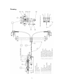
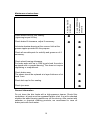
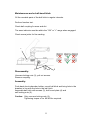
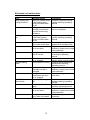
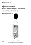
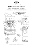
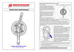
WAP disc brake technology
Assembly, operating and
maintenance instructions
Number
MA-025
Date
22.07.2010
1
Please read this operating and service manual before starting the
vehicle. It forms part of the warranty conditions.
Table of contents
Operating instructions
3
Handling
4
Descriptions
5
Characteristics
Components of the complete brake system
Mode of action
Checking the overrun shock absorbers
Drawing
7
Assembly and instructions for adjustment
8
Installation of the brake system to the vehicle
Adjustment/readjustment of the disc brake
Brake tests
Maintenance instructions
10
Maintenance works ball-head hitch
11
Elimination of malfunctions
12
2
Operating instructions:
Before every trip:
•
•
•
•
•
•
•
•
Do not overload the vehicle. The maximum permitted total
weight and support load must be strictly adhered to.
Make sure the load is fastened adequately. Avoid overloading
at one side by incorrect loading. Mount the load as low above
the axle(s) as possible. The load must be secured in
accordance with legal requirements.
Check tyre pressure / tyre condition / wheel mounting.
Check the position of the ball hitch (towing eye). The ball hitch
must fully enclose the ball of the towing vehicle and be locked
in place.
Fasten the breakaway cable at the towing vehicle.
Raise jockey wheel fully upwards and secure. The carrying
wheel should be aligned parallel with the direction of travel.
Release the handbrake.
Check the function of the lighting system.
We wish you a pleasant ride!
During every trip:
Avoid overstrain caused by irresponsible and inappropriate driving.
Avoid shock and impact loads on the axle(s). Adjust your driving speed
to load and road conditions.
After the first trip (details on page 8):
•
•
Check with a torque wrench that the wheel bolts are tightly
fitted.
Check braking system and readjust as required.
Important notes:
The legal requirements for type approved vehicle parts regulate that
alterations can only be made within the scope of EC-approvals, and they
must be made by the manufacturer itself. Subsequent welding in any
form is not permitted.
When installing spare parts it is strongly recommended to only use
original WAP-parts. If products of other manufacturers are used,
the product liability and warranty becomes void.
The repair of defects or the exchange of worn parts should be assigned
to a specialist workshop.
3
Handling
Coupling:
Lift the handle to open the ball coupling. Place the so opened hitch on
the ball of the towing vehicle and release the handle. After this allow the
handle to automatically slide back in its original position. With this the
hitch is locked and automatically secured.
Caution: After locking, the wear indicator at the side must indicate "OK"
or "+". The ball head should no longer be visible when
coupled, but must be enclosed by the coupling.
Connect the electrical lighting plug to the towing vehicle and check the
lighting.
Raise jockey wheel fully upwards and secure.
Release parking brake before setting off.
Note: The handle of the ball hitch and the handbrake lever must not be
used as a manoeuvring aid. There is a risk of damage to the internal
components, proper function can be impaired by this.
The maximum bearing load of the ball hitch must be strictly adhered to.
A minimum bearing load of 25 kg should be given. Negative bearing load
is not permitted.
Uncoupling:
Disconnect breakaway cable and electrical lighting plug.
Release and lower the jockey wheel.
First lift handle of the ball hitch, then lift forwards.
Lift the hitch of the ball or lift out with the jockey wheel.
Caution: The trailer must be secured with chocks or by activating the
parking brake!
4
Descriptions
Characteristics
The WAP disc brake system has been certified in accordance with EC
regulation 71/320 in its current adjustment regulation 98/12, and its
design has been approved for driving speeds up to 140 km/h.
The WAP disc brake system is the sole overrun disc brake with operates
mechanically only. Thus the handling by the user is as easy as with the
well known drum brakes.
Components of the complete brake system
The complete brake system is composed of the overrun hitch (A),
available optionally as flange or drawbar with towing eyelet, the
transmission device (B) and the disc breaks (C), which are attached
optionally to rubber suspension, torsion bar or a coil spring axles (D).
These components form a well coordinated unit. Combinations with
components of other manufacturers are only possible after prior
consultation with WAP and require our approval. If required, WAP will
issue calculations assessing that the brake system matches the
characteristics of a trailer, which may have to be presented at the vehicle
registration office.
Mode of action
Forward travel
When braking the towing vehicle, the trailer rises with the towing vehicle.
Thus the push rod (1) of the overrun device will slide into the housing
(2). The drawbar, embedded in the housing with two bushes, pushes so
with its back end on the reversing lever (3) embedded in the housing.
Through the resultant turning of the reversing lever the compressive
force is transmitted by the transmission device (usually rods) at the lower
end of the reversing lever to the equalizer (4) of the disc brake. From
there the overrun force is transmitted by the cable assembly (5) of the
disc brake to the clamping levers (6), which have a reverse effect. These
clamping levers affect a cylindrical sliding element (7), which presses the
internal brake shoe (8) against the friction plate (9). Simultaneously the
external brake shoe (10) is pressed against the friction plate via the float
frame.
Backward travel
5
The sliding of the drawbar into the overrun hitch when travelling
backwards creates a transmission as described above. By means of the
opposite rotary direction, the brake shoe pressed against the friction
plate is moved in rotary direction of the wheel. The articulated lever (11),
which joins the sliding element and the internal brake shoe, drops
sideways over its outer mounting points. Thus the application distance
runs out. The braking effect is reversed. When subsequently travelling
forward, the brake shoes will return to the original position by the
recoiling spring (12).
Parking brake / security brake
Owing to the greater application distance of the parking brake (13) in
comparison with the service brake, the internal braking shoe also
engages with the brake shoes when in reverse. For this purpose the
handbrake lever (13) has must be fully pulled. By this a braking effect, as
described before, can be achieved again. Also, by pulling the handbrake
lever the spring actuator (14) embedded in the brake linkage also gets
prestressed. Hence an unintentional releasing of the brakes in down
gradient can be avoided. In this case the spring actuator loosens and
readjusts the braking force. Before the trip, the breakaway cable (15),
which is fitted to the handbrake lever, must be connected with its strap to
the hitch hook of the towing vehicle. In the event of the trailer
disconnecting from the towing vehicle, the breakaway cable will be
activated through the parking brake.
Checking the overrun shock absorbers
The ball hitch together with the push bar has to be pushed into the
housing, after the relief the push bar must move forward on its own and
extend into normal position.
6
Drawing
7
Assembly and instructions for adjustment
Installation of the brake system to the vehicle
a.
b.
c.
d.
e.
f.
g.
Mount overrun hitch and axle(s) to the chassis.
Mount brake cable assembly (5) in the clamping levers (6) and fix by
bolt and nut (17).
Screw together brake cable assemblies of the axles in the thrust
bearing (welded to the axle tube).
Assemble equalizer of the transmission linkage with the brake
cables.
Join transmission linkage with the reversing lever of the overrun
hitch by using the fork head.
Pull handbrake lever to the second notch.
Tighten the clamp lock of the transmission linkage to the extent to
obtain a clearance of max. 2 mm within the brake system. When
doing this the spring actuator must not be prestressed by any
means. Secure clamp clock with hexagon nut against detachment.
Caution!
Make sure all equalizers are at right angles to the
transmission linkage (see page 7).
Adjustment/readjustment of the disc brake
When adjusting/readjusting the disc brakes it is important that the
drawbar of the overrun hitch is fully extended, and the handbrake lever is
in release position. Secure vehicle with chocks. Release transmission
device by opening the clamp lock. Jack up the wheel. Move the
adjustment nut (16) to the right by constantly rotating the wheel in
forward direction until the wheel is tightened. Through this the two brake
shoes get centred onto the friction plate. Consequently re-release the
adjustment nut until the wheel is just running free again. Repeat
procedure in the same way for remaining wheels. Only after all disc
brakes at the trailer have been adjusted/readjusted, the transmission
linkage will be refastened until a clearance of max. 2 mm is achieved.
Caution!
A too right adjustment/readjustment of the disc brakes
and/or the transmission linkages and/or the spring actuator
impairs the mobility of the brakes during reversing. Never
readjust the brake system only through the brake linkage.
Always first readjust the disc brakes as described, then
restress the transmission.
Brake tests
8
For a final check of the brake system setting, some brake stops with the
loaded trailer should be performed. As for brand-new trailers, or after
exchange of braking shoes, short distances with a lightly applied
handbrake should be driven. This way the brake shoes get slowly worn
in and adjust to the braking surface and friction plate. The setting of the
brake system is correct if the drawbar of the overrun hitch slides back by
about half of the maximum overrun distance (usually 80 mm) when
braking heavily.
9
Check wheel bolts for firm seating.
(tightening torque 95 Nm)
⊗
Check brake lift clearance, adjust if necessary.
⊗
Every 3000 driven
kilometres or
annually
After the first 50
kilometres
Maintenance instructions
Lubricate drawbar-bearing at the overrun hitch at the
grease nipples provided for this purpose.
Check all movable parts for mobility and grease or oil if
necessary.
⊗
⊗
⊗
Check wheel bearing allowance.
For brake axles with up to 1500 kg axle load, the axle is
equipped with a compact bearing. This does not require
regreasing or readjustment.
⊗
Check brake wear.
The shoes should be replaced at a layer thickness of at
least 3 mm.
⊗
Check hub cap for firm seating.
⊗
Check tyre wear.
⊗
General information
Do not clean the disc brake with a high-pressure cleaner. Should this
undertaken, all parts must be regreased and/or oiled. It must be checked
whether the wheel bearing gaskets are still functioning. After contact with
saltwater or chemical cleaning products, we recommend to rinse all
brake parts with fresh water.
10
Maintenance works ball-head hitch:
Oil the movable parts of the ball hitch in regular intervals.
Perform function test.
Check ball coupling for wear and dirt.
The wear indicator must be within the "OK" or "+" range when engaged.
Check screw joints for firm seating.
1
Disassembly:
2
3
4
Unscrew locking nuts (2), pull out screws.
Remove coupling.
Assembly:
Push back shock absorber holder, mount ball hitch and bring hole in the
drawbar in line with the hole in the ball hitch.
Assemble ball hitch with screws (3), half round plate (4) and
self locking nuts (2).
Caution: Only use new locking nuts (2).
Tightening torque of ca. 80-90 Nm required.
11
Elimination of malfunctions
Error
Jerky braking and
driving behaviour
Braking effect is too
low
Uneven braking
effect
It is difficult to move
vehicle back
Possible reason
Empty run (brake slack)
in the brake system,
pulling rod slides back
too far
Pulling rod can be
manually moved back
and forth without any
resistance
Empty run (brake slack)
in the brake system,
pulling rod slides back
too far
Transmission linkage too
stiff, hooks and/or jams
Brake cable assemblies
jam or are bent
Elimination
Readjust complete braking
system following operating
manual
Shock absorber is defect,
has to be replaced
Readjust complete braking
system following operating
manual
Free transmission linkage,
grease/oil all movable parts
Oil/grease brake cable
assembly, replace bent brake
cable assembly
Pulling rod of the overrun Lubricate pulling rod
hitch is too stiff
according to operating
manual
Brake shoes are worn,
Replace brake shoes, maybe
oily or clogged
replace wheel bearing gasket
Wheels brake unevenly Readjust wheel brakes and
transmission following
operating manual
One brake cable
Oil/grease brake cable
assembly too stiff or
assembly, replace bent brake
damaged
cable assembly
Braking shoes at one
Replace braking shoes on
wheel brake are worn,
both sides
oily or clogged
Transmission linkage too Readjust transmission
stiff
linkage following operating
manual
Wheel brake fitted too
Readjust wheel brake
tightly
following operating manual
Brake cable assemblies Oil/grease brake cable
jam or are bent
assembly, replace bent brake
cable assembly
Sliding element in caliper Mobilise and grease/oil if
jams, does not release necessary
12