1
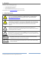
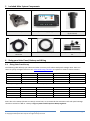
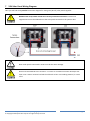
EcoOnline™ 24V Pump and Solar Battery Charging Kit Manual Installation & User Manual - Revised 28/01/2014 Optex Solar Pty. Ltd. www.EcoOnline.com.au email: [email protected] © Copyright 2012 Optex Solar Pty Ltd. All rights strictly reserved. This publication is protected by copyright law and unless otherwise specified is for your personal and non-commercial use only. No part of this publication may be reproduced or distributed by any process, electronic or otherwise, without the specific written permission of Optex Solar Pty Ltd. Trademarks appearing in this manual are the sole property of Optex Solar Pty Ltd or their respective owners. Nothing in this publication shall be construed as granting any express or implied license to use any intellectual property of Optex Solar Pty Ltd otherwise than for personal and non-commercial use only. Optex Solar Pty Ltd must not, to the full extent permitted by law, be held liable for any claim, cost (including legal costs), damage, expense, loss (including fines, penalties, set-offs and consequential loss) or liability arising from the use (or misuse) of any product described in this publication, unless expressly provided otherwise in this publication. Information as well as any products described in this publication are subject to change without notice. Eco Online™ Pump and Solar Battery Charging System -- Manual © Copyright 2012 Optex Solar Pty Ltd. All rights strictly reserved. Page 1 Contents 2 Key Terms .................................................................................................................................................................. 3 3 Warranties ................................................................................................................................................................ 4 4 Safety Requirements ................................................................................................................................................. 4 5 Included Main System Components ......................................................................................................................... 5 6 Sizing your Solar Panel, Battery and Wiring .............................................................................................................. 5 7 24V Solar Panel Wiring Diagram ............................................................................................................................... 7 8 Solar PV Panel Mounting .......................................................................................................................................... 8 9 Wiring Diagram ......................................................................................................................................................... 8 10 Pump Mounting .................................................................................................................................................... 9 11 Attaching and Mounting the Strainer/Filter ....................................................................................................... 10 12 Pump Plumbing ................................................................................................................................................... 12 13 Maintenance and Operating Instructions ........................................................................................................... 12 Eco Online™ Pump and Solar Battery Charging System -- Manual © Copyright 2012 Optex Solar Pty Ltd. All rights strictly reserved. Page 2 2 Key Terms Congratulations on the purchase of your EcoOnline™ pump and solar charger kit. Please note: This manual is INCOMPLETE. You MUST download the 1R/10Amp/24V/T Solar Charge Controller Manual when setting up this system. Please print both manuals out and keep them for your reference. Please take the time to read the entire manual before starting any work. Particular attention should be given to text contained in the following key terms. Please note EcoOnline has a strong product safety policy; do not install products without reading safety guidelines in the manual. Please report any product safety issues or near misses to [email protected] no matter how trivial. Indicates a SAFETY issue that is likely to cause injury or death if the user does not follow the instructions. Indicates a SAFETY issue that may cause injury or death if the user does not follow the instructions. Indicates a SAFETY issue that may cause injury or property damage if the user does not follow the instructions Refers to critically important information related to the correct functioning of the system. Refers to useful information for the optimal operation of the system Eco Online™ Pump and Solar Battery Charging System -- Manual © Copyright 2012 Optex Solar Pty Ltd. All rights strictly reserved. Page 3 3 Warranties EcoOnline™ offers the following Warranties 1 year limited Warranty on pumps 3 year limited Solar Controllers 20 year limited Warranty on all Motech Cell solar PV panels See EcoOnline.com.au Terms and Conditions page for further details. 4 Safety Requirements Please note: This manual is INCOMPLETE. You MUST download the 1R/10Amp/24V/T Solar Charge Controller Manual when setting up this system. Please download from www.EcoOnline.com.au/downloads This appliance is not intended for use by persons (including children) with reduced physical, sensory or mental capabilities, or lack of experience and knowledge, unless they have been given supervision or instruction concerning use of the appliance by a person responsible for their safety. Children should be supervised to ensure that they do not play with the appliance. This pump is not recommended for potable water (drinking water) application. For applications involving fish we recommend the pump be run in a bucket of water to flush out any excess grease prior to installation. Building regulations vary from state to state and MUST override any instructions supplied in this manual. It is the responsibility of the purchaser/installer to check that installations comply with any relevant state laws and regulations. The EcoOnline™ Solar Pump is not self-priming. The pump must be flood primed by installing below the waterline of the water to be pumped. An inline strainer/filter MUST be used where there is a chance of dirt or debris making its way into the pump. Eco Online™ Pump and Solar Battery Charging System -- Manual © Copyright 2012 Optex Solar Pty Ltd. All rights strictly reserved. Page 4 5 6 Included Main System Components DC Pump 10Amp Solar Charging Regulator PVC 316Stainless Mesh Strainer (if purchased) 2 x 1.0mm2 5m wire with connector 1 x 2.5 mm2, 2m Battery Wire 10Amp Fuse holder, 15Amp fuse kit. Sizing your Solar Panel, Battery and Wiring 6.1 Sizing Solar Panel Array The following table will help you understand what run times you’ll achieve with panel wattage. Note: these run times are yearly averaged. Please use our Solar Panel Sizing Calculator to explore run times in various seasons. 2 x 20W = 40W 2 x 40W = 80W Melbourne 3.2h 6.4h Brisbane 3.7h 7.4h Perth 4h 8h Hobart 3h 6h Table 1) Average daily pump run times for a 45W 24V pump 2 x 60W = 120W 9.6h 11.1h 12h 9h 2 x 80W = 160W 12.8h 14.8h 16h 12h 2 x 10W = 20W 2 x 20W = 40W Melbourne 3h 5h Brisbane 3h 5h Perth 3h 7h Hobart 2h 4h Table 2) Average daily pump run times for a 25W 24V pump 2 x 40W = 80W 11h 11h 14h 8h 2 x 60W = 120W 15h 15h 21h 12h Note: due to the 10Amp (derate to 7.5Amp) current limit, we recommend that maximum total solar panel wattage should not exceed 2 x 90W or 7.5Amps. Larger systems would require a 20Amp regulator. Eco Online™ Pump and Solar Battery Charging System -- Manual © Copyright 2012 Optex Solar Pty Ltd. All rights strictly reserved. Page 5 6.2 Sizing You Battery Bank As a general rule we recommend sizing the battery bank to a minimum of 3 “days of autonomy“, meaning the battery should supply enough energy to run for three days without solar input. Battery sizing can be worked out as: Battery Ah Rating = Days of Autonomy X Pump Amp Usage X Daily Run Time Hence, for example for a 20W (0.833 Amp) pump and a desired 6 hours per night running time you would need a 3 x 0.83A x 6h = 15Ah 24V battery (or 2 x 15Ah 12V batteries connected in series). When sizing your solar array and battery you must check that the maximum current produced by the chosen solar panel(s) array can never exceed the maximum allowable charging current for the battery being charged. Always follow the battery manufacturer’s charging instructions. Please note: panels can produce up to 30% more power than the panels rated power under extraordinary solar conditions. 6.3 Sizing Wiring Please use our Solar Wire Sizing Calculator this will help you understand the factors involved in sizing wire gauges. A 24V system allows for greater wire runs without great voltage. Eco Online™ Pump and Solar Battery Charging System -- Manual © Copyright 2012 Optex Solar Pty Ltd. All rights strictly reserved. Page 6 7 24V Solar Panel Wiring Diagram Here you will find the in parallel connection diagram for wiring two (36 cell) solar panels together. NEVER screw clamp solder tinned wires to the junction box terminals. Positive and negative wires must be soldered onto the solar panels terminals in the junction box. Note: Solar panels connected in series must be the same wattage. Wires must be soldered to the terminal – if a loose or corroded connection develops over time it can create a resistive load which could melt or burn surrounding material, or cause a fire. Eco Online™ Pump and Solar Battery Charging System -- Manual © Copyright 2012 Optex Solar Pty Ltd. All rights strictly reserved. Page 7 8 Solar PV Panel Mounting 1) If mounting on a roof we recommend a 20-30mm air gap be used between the solar panel and roof structure. Aluminium angles (20-30mm) should be attached to the back of the solar panel for mounting purposes using the back mounting holes. Important: Wind loading should be considered. When mounting panels on a Veranda or Patio or Gazebo roof structure, panels should be mounted as low as possible to reduce the risk of lightning strikes. 9 Wiring Diagram Eco Online™ Pump and Solar Battery Charging System -- Manual © Copyright 2012 Optex Solar Pty Ltd. All rights strictly reserved. Page 8 10 Pump Mounting The pump should be supported such that there is a minimum amount of stress on the pump’s inlet and outlet piping. The pump body should not be suspended by its inlets and outlets without support. The pump should be installed in a way which allows easy access dismantling for maintenance. Connection of the pipe work to the pump should permit the removal of the pump without the need to cut the pipe work. Make sure all lines are flushed clean with water before connecting pumps. If the water environment contains debris ALWAYS use an inline filter with a rating of 360 Microns or smaller. 10.1 Allowed Mounted Pump Orientation Eco Online™ Pump and Solar Battery Charging System -- Manual © Copyright 2012 Optex Solar Pty Ltd. All rights strictly reserved. Page 9 11 Attaching and Mounting the Strainer/Filter 11.1 Allowed Mounted Strainer Orientations The pump and strainer must be mounted so that they both automatically flood prime without needing to force water through. This is critical as small ever present air bubbles can build up in air pockets. A pump can become air-locked and be damaged if a sufficiently large air bubble is released while the pump is working under pressure. The supplied inline strainer/filter can be used as a pre-strainer or as an in-line strainer. Note when mounting the canister as a pre-strainer the water flow must be against the water flow arrow marked on the canister. Eco Online™ Pump and Solar Battery Charging System -- Manual © Copyright 2012 Optex Solar Pty Ltd. All rights strictly reserved. Page 10 11.2 Pre-Strainer Mounting Configuration Before mounting the pre-filter you need to drill 3-5mm holes in the side of the cylinder (DO NOT drill top). The size of and number of these holes will depend on the application. The internal mesh will form a secondary filter. You may also require a pond sponge wrapped around the cylinder depending on the application. Note water flow goes against the actual water flow markings on the filter for this configuration. Warm the filter cylinder in 40˚C water to soften and prevent cracking during drilling. A 25mm PVC end cap can be inserted on the end of the filter. 11.3 In-line Strainer Mounting Configurations In this configuration it is critical that the filter canister is oriented in an allowable orientation (see above). The filter must be able to self purge air pockets else there may result an air lock in the pump. When mounting in a pond a pre-strainer sponge is also be connected to the filter inlet as a secondary filter. If required. Eco Online™ Pump and Solar Battery Charging System -- Manual © Copyright 2012 Optex Solar Pty Ltd. All rights strictly reserved. Page 11 12 Pump Plumbing For non-chlorinated water applications we recommend PE lines and air tight compressions for all plumbing on the suction side of the pump. If there is any chance of flush back through the pump in the reverse direction then airtight fitting should also be used on the outlet side of the pump. Do not over-tighten pump head thread fittings. Always use Teflon tape. Fittings should be hand tightened only until residence is felt, after an extra ½ turn will seal perfectly. Never carry the pump by the electric supply cable as this may damage the pump and make it unsafe. 13 Maintenance and Operating Instructions Important: before carrying out any system maintenance you MUST check for any manual updates and download the latest installation manual from www.EcoOnline.com.au/downloads The inline filter should be cleaned regularly. The pump can be dismantled and ceramic rotor shaft regreased once per year. Care should be taken during dismantling as the pump contains small polymer washers on the rotor shaft. Fatigued, weathered, loose and/or corroded wiring or electrical connections poses a fire risk even at low voltage. The systems wiring should be checked periodically for any wear, cracking resulting from UV damage of insulation on wiring and corrosion of any solder or controller connections. Any effected parts should be replaced at the first sign of damage. Never run a 12-24V cable near or in the same compartment or conduit as other 240V cables due to the chance of mistaking the two cables at some later point in time during installation or servicing. Eco Online™ Pump and Solar Battery Charging System -- Manual © Copyright 2012 Optex Solar Pty Ltd. All rights strictly reserved. Page 12