1
FOREWORD
GROUP INDEX
This manual contains an introductory description on
the SUZUKI UY125/S and procedures for its inspection/service and overhaul of its main components.
Other information considered as generally known is
not included.
Read the GENERAL INFORMATION section to
familiarize yourself with the motorcycle and its maintenance. Use this section as well as other sections
to use as a guide for proper inspection and service.
This manual will help you know the motorcycle better so that you can assure your customers of fast
and reliable service.
* This manual has been prepared on the basis
of the latest specifications at the time of publication. If modifications have been made since
then, differences may exist between the content of this manual and the actual motorcycle.
* Illustrations in this manual are used to show
the basic principles of operation and work
procedures. They may not represent the
actual motorcycle exactly in detail.
* This manual is written for persons who have
enough knowledge, skills and tools, including
special tools, for servicing SUZUKI motorcycles. If you do not have the proper knowledge
and tools, ask your authorized SUZUKI
motorcycle dealer to help you.
GENERAL INFORMATION
1
PERIODIC MAINTENANCE
2
ENGINE
3
FUEL AND LUBRICATION
SYSTEM
4
CHASSIS
5
ELECTRICAL SYSTEM
6
SERVICING INFORMATION
7
!
Inexperienced mechanics or mechanics
without the proper tools and equipment
may not be able to properly perform the
services described in this manual.
Improper repair may result in injury to the
mechanic and may render the motorcycle
unsafe for the rider and passenger.
THAI SUZUKI MOTOR CO., LTD.
© COPYRIGHT THAI SUZUKI MOTOR CO., LTD. 2005
http://www.motorcycle.in.th
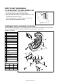
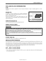
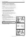
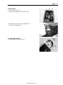
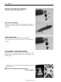
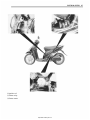
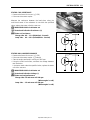
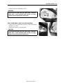
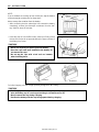
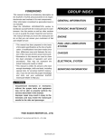
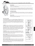
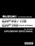
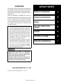
HOW TO USE THIS MANUAL
TO LOCATE WHAT YOU ARE LOOKING FOR:
1. The text of this manual is divided into sections.
2. The section titles are listed in the GROUP INDEX.
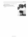
3. Holding the manual as shown at the right will allow you to find
the first page of the section easily.
4. The contents are listed on the first page of each section to
help you find the item and page you need.
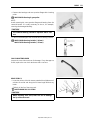
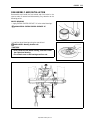
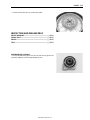
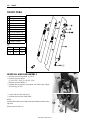
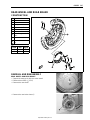
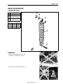
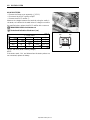
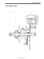
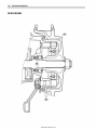
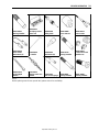
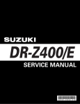
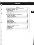
COMPONENT PARTS AND WORK TO BE DONE
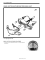
Under the name of each system or unit, is its exploded view. Work instructions and other service information
such as the tightening torque, lubricating points and locking agent points, are provided.
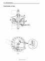
Example: Front wheel
1
2
3
4
5
6
7
8
9
0
A
B
C
D
A
B
C
Spacer
Dust seal
Bearing
Front wheel spacer
Front wheel
Bearing
Front brake shoe
Dust seal
Speedometer drive
gear
Front brake camshaft
Front brake panel
Speedometer driven
gear
Front brake cam lever
Front axle
Front axle nut
Spoke nipple
Front brake cam lever
bolt
"
ITEM
A
B
C
N·m
42
4.5
8
kgf-m
4.2
0.45
0.8
http://www.motorcycle.in.th
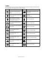
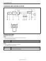
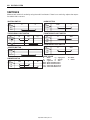
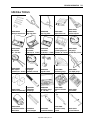
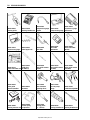
SYMBOL
Listed in the table below are the symbols indicating instructions and other information necessary for servicing. The meaning of each symbol is also included in the table.
SYMBOL
DEFINITION
SYMBOL
DEFINITION
Torque control required.
Data beside it indicates specified
torque.
Apply THREAD LOCK SUPER “1360”.
99000-32130
Apply oil. Use engine oil unless otherwise specified.
Use fork oil.
99000-99044-10G
Apply molybdenum oil solution.
(Mixture of engine oil and SUZUKI
MOLY PASTE in a ratio of 1:1)
Apply or use brake fluid.
Apply SUZUKI SUPER GREASE “A”.
99000-25010
Measure in voltage range.
Apply SUZUKI SILICONE GREASE.
99000-25100
Measure in current range.
Apply SUZUKI MOLY PASTE.
99000-25140
Measure in resistance range.
Apply SUZUKI BOND “1215”.
99000-31110
Measure in diode test range.
Apply SUZUKI BOND “1207B”.
99000-31140
Measure in continuity test range.
Apply THREAD LOCK SUPER “1322”.
99000-32110
Use special tool.
Apply THREAD LOCK “1342”.
99000-32050
Indication of service data.
http://www.motorcycle.in.th
White Page
http://www.motorcycle.in.th
GENERAL INFORMATION
1-1
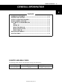
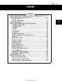
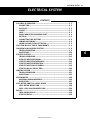
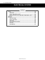
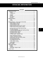
GENERAL INFORMATION
1
CONTENTS
WARNING/CAUTION/NOTE........................................................................
GENERAL PRECAUTIONS .........................................................................
SUZUKI UY125K6/SK6 (’06-MODEL) .........................................................
SERIAL NUMBER LOCATION ....................................................................
FUEL AND OIL RECOMMENDATION ........................................................
FUEL......................................................................................................
ENGINE OIL ..........................................................................................
REDUCTION GEAR OIL .......................................................................
BRAKE FLUID (UY125S) ......................................................................
FRONT FORK OIL.................................................................................
BREAK-IN PROCEDURES..........................................................................
SPECIFICATIONS........................................................................................
111111111111-
2
2
4
4
5
5
5
5
5
5
5
6
COUNTRY AND AREA CODES
The following codes stand for the applicable country(-ies) and area(-s).
CODE
P-14 (UY125)
P-14 (UY125S)
COUNTRY or AREA
Thailand
Thailand
http://www.motorcycle.in.th
EFFECTIVE FRAME NO.
CF48A-TH !!!!!! –
CF48B-TH !!!!!! –
1-2
GENERAL INFORMATION
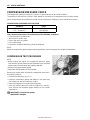
WARNING/CAUTION/NOTE
Please read this manual and follow its instructions carefully. To emphasize special information, the symbol
and the words WARNING, CAUTION and NOTE have special meanings. Pay special attention to the messages highlighted by these signal words.
!
Indicates a potential hazard that could result in death or injury.
"
Indicates a potential hazard that could result in motorcycle damage.
NOTE:
Indicates special information to make maintenance easier or instructions clearer.
Please note, however, that the warnings and cautions contained in this manual cannot possibly cover all
potential hazards relating to the servicing, or lack of servicing, of the motorcycle. In addition to the WARNINGS and CAUTIONS stated, you must use good judgement and basic mechanical safety principles. If you
are unsure about how to perform a particular service operation, ask a more experienced mechanic for
advice.
GENERAL PRECAUTIONS
!
* Proper service and repair procedures are important for the safety of the service mechanic and
the safety and reliability of the motorcycle.
* When 2 or more persons work together, pay attention to the safety of each other.
* When it is necessary to run the engine indoors, make sure that exhaust gas is forced outdoors.
* When working with toxic or flammable materials, make sure that the area you work in is wellventilated and that you follow all of the material manufacturer’s instructions.
* Never use gasoline as a cleaning solvent.
* To avoid getting burned, do not touch the engine, engine oil, radiator and exhaust system
until they have cooled.
After servicing the fuel, oil, water, exhaust or brake systems, check all lines and fittings related
to the system for leaks.
http://www.motorcycle.in.th
GENERAL INFORMATION
"
* If parts replacement is necessary, replace the parts with Suzuki Genuine Parts or their equivalent.
* When removing parts that are to be reused, keep them arranged in an orderly manner so that
they may be reinstalled in the proper order and orientation.
* Be sure to use special tools when instructed.
* Make sure that all parts used in reassembly are clean. Lubricate them when specified.
* Use the specified lubricant, bond, or sealant.
* When removing the battery, disconnect the negative cable first and then the positive cable.
* When reconnecting the battery, connect the positive cable first and then the negative cable,
and replace the terminal cover on the positive terminal.
* When performing service to electrical parts, if the service procedures do not require use of
battery power, disconnect the negative cable from the battery.
* When tightening the cylinder head or case bolts and nuts, tighten the larger sizes first.
Always tighten the bolts and nuts diagonally from the inside toward outside and to the specified tightening torque.
* Whenever you remove oil seals, gaskets, packing, O-rings, locking washers, self-locking
nuts, cotter pins, circlips and certain other parts as specified, be sure to replace them with
new ones. Also, before installing these new parts, be sure to remove any left over material
from the mating surfaces.
* Never reuse a circlip. When installing a new circlip, take care not to expand the end gap larger
than required to slip the circlip over the shaft. After installing a circlip, always ensure that it is
completely seated in its groove and securely fitted.
* Use a torque wrench to tighten fasteners to the specified torque. Wipe off grease and oil if a
thread is smeared with them.
* After reassembling, check parts for tightness and proper operation.
* To protect the environment, do not unlawfully dispose of used motor oil and other fluids: batteries and tires.
* To protect Earth’s natural resources, properly dispose of used motorcycle and parts.
http://www.motorcycle.in.th
1-3
1-4
GENERAL INFORMATION
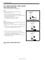
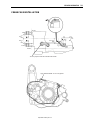
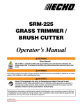
SUZUKI UY125K6/SK6 (’06-MODEL)
RIGHT SIDE (UY125S)
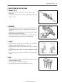
LEFT SIDE (UY125)
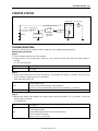
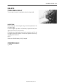
SERIAL NUMBER LOCATION
The frame serial number or V.I.N. (Vehicle Identification Number) 1 is stamped on the left side of the steering head pipe. The engine serial number 2 is located on the left side of the crankcase. These numbers are
required especially for registering the machine and ordering spare parts.
http://www.motorcycle.in.th
GENERAL INFORMATION
1-5
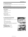
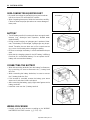
FUEL AND OIL RECOMMENDATION
FUEL
Gasoline used should be graded 91 octane (Research Method) or higher. Unleaded gasoline is recommended.
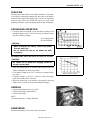
ENGINE OIL
Oil quality is a major contributor to your engine’s performance
and life. Always select good quality engine oil. Use of SF/SG or
SH/SJ in API with MA in JASO.
Suzuki recommends the use of SAE 10W-40 engine oil. If SAE
10W-40 engine oil is not available, select an alternative according to the right chart.
REDUCTION GEAR OIL
Use a good quality SAE 10W-40 multi-grade motor oil.
BRAKE FLUID (UY125S)
Specification and classification: DOT 4
!
Since the brake system of this motorcycle is filled with a glycol-based brake fluid by the manufacturer, do not use or mix different types of fluid such as silicone-based and petroleum-based
fluid for refilling the system, otherwise serious damage will result.
Do not use any brake fluid taken from old or used or unsealed containers.
Never re-use brake fluid left over from a previous servicing, which has been stored for a long
period.
FRONT FORK OIL
Use SUZUKI FORK OIL G10 (#10) or an equivalent fork oil.
BREAK-IN PROCEDURES
During manufacture only the best possible materials are used and all machined parts are finished to a very
high standard but it is still necessary to allow the moving parts to “BREAK-IN” before subjecting the engine
to maximum stresses. The future performance and reliability of the engine depends on the care and restraint
exercised during its early life. Refer to the following throttle position recommendations.
• Keep to these break-in throttle positions:
Initial
800 km: Less than 1/2 throttle
Up to 1 600 km: Less than 3/4 throttle
• Upon reaching an odometer reading of 1 600 km you can subject the motorcycle to full throttle operation
for short periods of time.
http://www.motorcycle.in.th
1-6
GENERAL INFORMATION
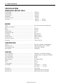
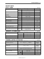
SPECIFICATIONS
DIMENSIONS AND DRY MASS
Overall length..........................................................................
Overall width ...........................................................................
Overall height..........................................................................
Wheelbase ..............................................................................
Ground clearance ...................................................................
Dry mass.................................................................................
1 859 mm
654 mm
1 046 mm
1 244 mm
145 mm
94.2 kg .......... UY125
95.5 kg .......... UY125S
ENGINE
Type ........................................................................................
Number of cylinders ................................................................
Bore ........................................................................................
Stroke......................................................................................
Displacement ..........................................................................
Compression ratio...................................................................
Carburetor...............................................................................
Air cleaner...............................................................................
Starter system.........................................................................
Lubrication system ..................................................................
Idle speed ...............................................................................
Four stroke, forced air-cooled, OHC
1
53.5 mm
55.2 mm
124 cm³
9.6 : 1
MIKUNI BS26
Paper element
Electric and kick
Wet sump
1 600 ± 100 rpm
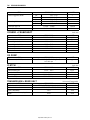
TRANSMISSION
Clutch......................................................................................
Reduction ratio........................................................................
Final reduction ratio ................................................................
Drive system ...........................................................................
Dry shoe, automatic, centrifugal type
Variable change (2.700 – 0.825)
9.264 (49/17 × 45/14)
V-belt drive
CHASSIS
Front suspension ....................................................................
Rear suspension .....................................................................
Front fork stroke......................................................................
Rear wheel travel ....................................................................
Steering angle.........................................................................
Caster .....................................................................................
Trail .........................................................................................
Turning radius .........................................................................
Front brake..............................................................................
Rear brake ..............................................................................
Front tire size ..........................................................................
Rear tire size...........................................................................
Telescopic, coil spring, oil damped
Swingarm type, coil spring, oil damped
85 mm
80 mm
45° (right and left)
25.6°
100 mm
1.9 m
Drum brake .......... UY125
Disc brake ............ UY125S
Drum brake
70/90-14 M/C (34 P), tube type
80/90-14 M/C (40 P), tube type
http://www.motorcycle.in.th
GENERAL INFORMATION
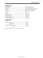
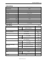
ELECTRICAL
Ignition type.............................................................................
Ignition timing ..........................................................................
Spark plug ...............................................................................
Battery .....................................................................................
Generator ................................................................................
Fuse ........................................................................................
Headlight .................................................................................
Turn signal light.......................................................................
Brake light/Taillight ..................................................................
Speedometer light ...................................................................
High beam indicator light.........................................................
Turn signal indicator light ........................................................
Electronic ignition (CDI)
10° B.T.D.C.at 1 600 rpm
NGK CR6HSA or DENSO U20FSR-U
12 V 12.6 kC (3.5 Ah)/10 HR
Single-phase A.C. generator
10 A
12 V 30/30 W
12 V 10 W
12 V 18/5 W
12 V 3.4 W
12 V 1.7 W
12 V 1.7 W
CAPACITIES
Fuel tank .................................................................................
3.7 L
Engine oil, oil change .............................................................
950 ml
with filter change................................................... 1 050 ml
overhaul ................................................................ 1 100 ml
Reduction gear oil, oil change................................................
100 ml
overhaul ..................................................
110 ml
These specifications are subject to change without notice.
http://www.motorcycle.in.th
1-7
White Page
http://www.motorcycle.in.th
PERIODIC MAINTENANCE
2-1
PERIODIC MAINTENANCE
CONTENTS
PERIODIC MAINTENANCE SCHEDULE ......................................................
PERIODIC MAINTENANCE CHART ....................................................
LUBRICATION POINTS .......................................................................
MAINTENANCE AND TUNE-UP PROCEDURES .........................................
AIR CLEANER ......................................................................................
EXHAUST PIPE BOLT AND MUFFLER MOUNTING NUT .................
COOLING FAN FILTER .......................................................................
VALVE CLEARANCE ...........................................................................
SPARK PLUG .......................................................................................
FUEL LINE ............................................................................................
ENGINE OIL AND OIL FILTER ............................................................
ENGINE IDLE SPEED ..........................................................................
THROTTLE CABLE PLAY ...................................................................
DRIVE BELT .........................................................................................
REDUCTION GEAR BOX OIL ..............................................................
BRAKE .................................................................................................
BRAKE HOSE AND BRAKE FLUID (UY125S) ...................................
TIRE AND WHEELS .............................................................................
STEERING ............................................................................................
FRONT FORK .......................................................................................
REAR SUSPENSION ...........................................................................
CHASSIS BOLTS AND NUTS .............................................................
COMPRESSION PRESSURE CHECK ..........................................................
COMPRESSION TEST PROCEDURE .................................................
OIL PRESSURE CHECK ...............................................................................
OIL PRESSURE TEST PROCEDURE .................................................
AUTOMATIC CLUTCH INSPECTION ...........................................................
1. INITIAL ENGAGEMENT INSPECTION ............................................
2. CLUTCH “LOCK-UP” INSPECTION ...............................................
http://www.motorcycle.in.th
2- 2
2- 2
2- 3
2- 4
2- 4
2- 5
2- 5
2- 6
2- 7
2- 8
2- 8
2-10
2-10
2-11
2-11
2-12
2-13
2-15
2-17
2-17
2-17
2-18
2-20
2-20
2-21
2-21
2-22
2-22
2-22
2
6
2-2
PERIODIC MAINTENANCE
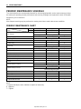
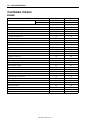
PERIODIC MAINTENANCE SCHEDULE
The chart below lists the recommended intervals for all the required periodic service work necessary to keep
the motorcycle operating at peak performance and economy. Mileages are expressed in terms of kilometer
and time for your convenience.
NOTE:
More frequent servicing may be performed on motorcycles that are used under severe conditions.
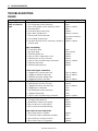
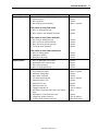
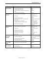
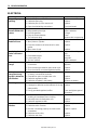
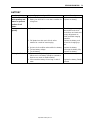
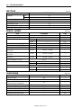
PERIODIC MAINTENANCE CHART
Item
Interval km
months
Air cleaner
Exhaust pipe bolt and muffler bolt
Cooling fan filter
Valve clearance
Spark plug
Fuel line
Engine oil
Engine oil filter
Idle rpm
Throttle cable play
Drive belt
Final reduction gear box oil
Brake
Brake hose (UY125S)
Brake fluid (UY125S)
Tire and wheels
Steering
Front fork
Rear suspension
Chassis bolt and nut
1 000
5
—
T
I
—
—
R
R
I
I
—
—
I
—
—
—
I
—
—
T
4 000
20
I
Replace every 12 000 km.
—
Clean every 3 000 km.
I
I
I
Replace every four years.
R
—
I
I
I
—
I
I
Replace every four years.
I
Replace every two years.
I
—
—
—
T
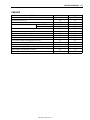
NOTE:
I = Inspect and adjust, clean, lubricate or replace as necessary
R = Replace
T = Tighten
http://www.motorcycle.in.th
8 000
40
I
T
I
R
I
R
R
I
I
I
I
I
I
I
I
I
I
I
T
PERIODIC MAINTENANCE
2-3
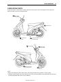
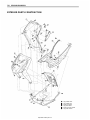
LUBRICATION POINTS
Proper lubrication is important for smooth operation and long life of each working part of the motorcycle.
Major lubrication points are indicated below.
Rear brake
lever holder
Footrest pivot
Side-stand pivot
and spring hook
Speedometer
cable
Throttle cable
Center stand pivot
and spring hook
Front brake
lever holder
Speedometer
gearbox
NOTE:
* Before lubricating each part, clean off any rusty spots and wipe off any grease, oil, dirt or grime.
* Lubricate exposed parts which are subject to rust, with a rust preventative spray whenever the motorcycle
has been operated under wet or rainy conditions.
http://www.motorcycle.in.th
2-4
PERIODIC MAINTENANCE
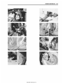
MAINTENANCE AND TUNE-UP
PROCEDURES
This section describes the servicing procedures for each item of
the Periodic Maintenance requirements.
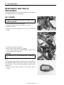
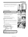
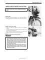
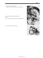
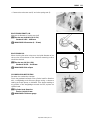
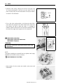
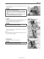
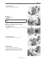
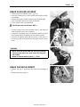
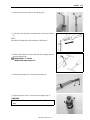
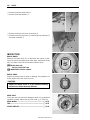
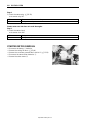
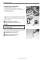
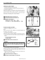
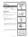
AIR CLEANER
Inspect every 4 000 km (20 months) and replace every
12 000 km thereafter.
•
•
•
•
Place the motorcycle on the side stand.
Remove the frame cover (left and right). (!5-10)
Remove the hook 1.
Remove the air cleaner element box cap 2 by removing the
screws.
• Remove the air cleaner element 3.
• Inspect the air cleaner element for clogging.
If the air cleaner element is clogged with dust, replace the air
cleaner element with a new one.
"
Do not blow the air cleaner element with compressed
air.
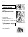
NOTE:
If driving under dusty conditions, replace the air cleaner element
more frequently. Make sure that the air cleaner is in good condition at all times. The life of the engine depends largely on this
component.
• Install a new air cleaner element in the reverse order of
removal.
http://www.motorcycle.in.th
PERIODIC MAINTENANCE
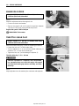
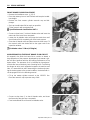
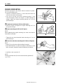
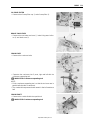
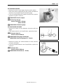
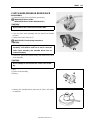
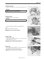
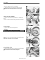
• Remove the drain plug from the air cleaner box to allow any
water to drain out.
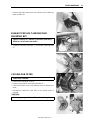
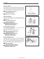
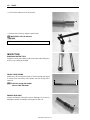
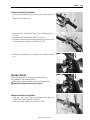
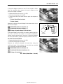
EXHAUST PIPE BOLT AND MUFFLER
MOUNTING NUT
Tighten initially at 1 000 km (5 months) and every
8 000 km (40 months) thereafter.
• Tighten the exhaust pipe bolts 1 and muffler mounting bolts
2.
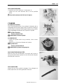
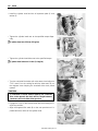
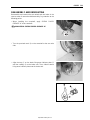
COOLING FAN FILTER
Clean every 3 000 km.
• Remove the cooling fan cover 1.
• Remove the holder 2 and cooling fan filter 3.
• Clean the fan filter in the same manner of the air cleaner element.
• Reinstall the cleaned or new filter in the reverse order of
removal.
"
Do not apply engine oil to the filter after cleaning it.
http://www.motorcycle.in.th
2-5
2-6
PERIODIC MAINTENANCE
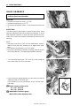
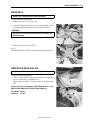
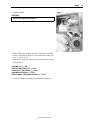
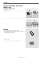
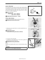
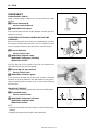
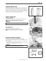
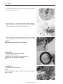
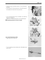
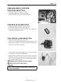
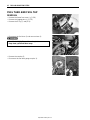
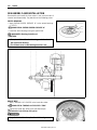
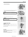
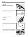
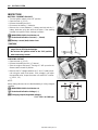
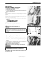
VALVE CLEARANCE
Inspect initially at 1 000 km (5 months) and every
4 000 km (20 months) thereafter.
REMOVAL
• Remove the frame front cover. (!5-8)
• Remove the spark plug. (!2-7)
• Disconnect the breather hoses 1 and remove the head cover
2.
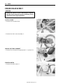
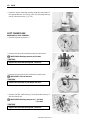
INSPECTION
The valve clearance specification is same for both valves. Valve
clearance adjustment must be checked and adjusted, 1) at the
time of periodic inspection, 2) when the valve mechanism is serviced, and 3) when the camshaft is disturbed by removing it for
servicing.
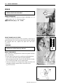
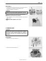
NOTE:
* The piston must be at (TDC) on the compression stroke in
order to check the valve clearance or to adjust valve clearance.
* The clearance specification is for COLD state.
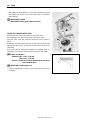
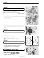
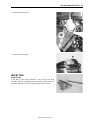
* To turn the crankshaft for clearance checking, rotate in the normal running direction. The spark plug should be removed.
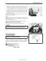
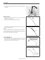
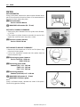
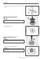
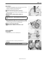
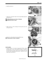
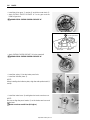
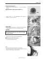
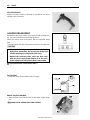
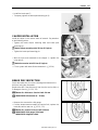
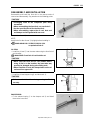
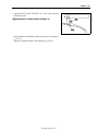
• Turn crankshaft to bring the “TDC” mark A on the cooling fan
to the index mark B on the crankcase.
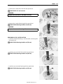
• Insert a thickness gauge between the valve stem end and the
adjusting screw on the rocker arm.
If the clearance is out of specification, bring it into the specified range.
# Valve clearance (when cold):
IN.: 0.04 – 0.07 mm
EX.: 0.10 – 0.15 mm
Adjuster
Lock-nut
$ 09900-20803: Thickness gauge
09917-13210: Valve adjusting driver
http://www.motorcycle.in.th
PERIODIC MAINTENANCE
2-7
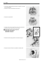
• After finishing the valve clearance adjustment, reinstall the following items.
* Cylinder head cover (!3-11)
* Spark plug and plug cap (!2-7)
* Frame front cover (!5-8)
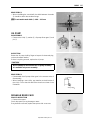
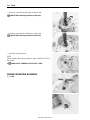
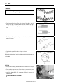
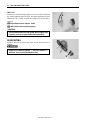
SPARK PLUG
Inspect at 4 000 km (20 months) and replace every
8 000 km (40 months) thereafter.
REMOVAL
• Remove the frame front cover. (!5-8)
• Disconnect the spark plug cap and remove the spark plug.
$ 09930-10121: Spark plug socket wrench set
Standard
NGK
CR6HSA
DENSO
U20FSR-U
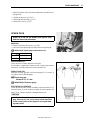
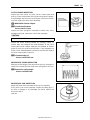
CARBON DEPOSIT
Check to see the carbon deposit on the plug.
If the carbon is deposited, remove it with a spark plug cleaner
machine or carefully using a tool with a pointed end.
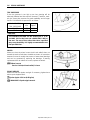
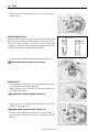
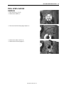
SPARK PLUG GAP
Measure the plug gap with a thickness gauge if it is correct. If
not, adjust it to the following gap.
# Spark plug gap:
Standard: 0.6 – 0.7 mm
$ 09900-20803: Thickness gauge
ELECTRODE’S CONDITION
Check to see the worn or burnt condition of the electrodes. If it is
extremely worn or burnt, replace the plug. And also replace the
plug if it has a broken insulator, damaged thread, etc.
"
0.6 – 0.7 mm
Confirm the thread size and reach when replacing the
plug. If the reach is too short, carbon will be deposited
on the screw portion of the plug hole and engine damage may result.
http://www.motorcycle.in.th
2-8
PERIODIC MAINTENANCE
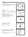
INSTALLATION
"
Before using a spark plug wrench, carefully turn the
spark plug by finger into the threads of the cylinder
head to prevent damage the aluminum threads.
• Install the spark plug to the cylinder head by finger tight, and
then tighten it to the specified torque.
% Spark plug: 11 N·m (1.1 kgf-m)
$ 09930-10121: Spark plug wrench set
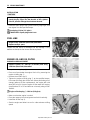
FUEL LINE
Inspect every 4 000 km (20 months) thereafter.
Replace every 4 years.
Inspect the fuel hoses for damage and fuel leakage. If any
defects are found, the fuel hoses must be replaced.
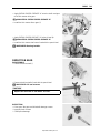
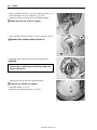
ENGINE OIL AND OIL FILTER
ENGINE OIL REPLACEMENT
Replace initially at 1 000 km (5 months) and every
4 000 km (20 months) thereafter.
• Keep the motorcycle upright.
• Place an oil pan below the engine. Drain oil by removing the
engine oil drain plug 1.
• Remove the oil filler cap 2.
• Tighten the engine oil drain plug 1 to the specified torque.
Pour new oil through the oil filler hole. When performing an oil
change (without oil filter replacement), the engine will hold
about 950 ml of oil. Use an engine oil that meets API service
classifications SF or SG and that has a viscosity rating of SAE
10W-40.
% Engine oil drain plug 1: 18 N·m (1.8 kgf-m)
•
•
•
•
Make sure that the engine is cooled.
Place the motorcycle on level ground and hold it vertically.
Install the oil filler cap 2.
Start the engine and allow it to run for a few minutes at idling
speed.
http://www.motorcycle.in.th
PERIODIC MAINTENANCE
• Turn off the engine and wait minute, then check the oil level
by removing the filler cap 2. If the level is below mark “L”,
add oil to “F” level. (off the center stand, do not screw the filler
cap.)
If the level is above mark “F”, drain oil to “F” level.
2-9
F
L
OIL FILTER REPLACEMENT
Replace initially at 1 000 km (5 months) and every
8 000 km (40 months) thereafter.
• Drain engine oil as described in the engine oil replacement
procedure.
• Remove the oil filter cap 1 and oil filter 2.
• Replace the oil filter with a new one.
• Install the spring 3 correctly.
• Apply engine oil lightly to the O-rings 4 and 5.
• Install the oil filter cap and tighten the bolts securely.
% Oil filter cap bolt: 10 N·m (1.0 kgf-m)
NOTE:
* Before installing the new oil filter and oil filter cap, make sure
that the spring 3 and new O-rings 4, 5 are installed correctly.
* The arrow mark A on the oil filter cap should be positioned
down.
* Fit the clamp to the bolt B.
• Add new engine oil and check the oil level as described in the
engine oil replacement procedure.
# Oil viscosity and classification:
10W-40 (SAE)/SF or SG (API)
# NECESSARY AMOUNT OF ENGINE OIL
Oil change
: 950 ml
Oil and filter change : 1 050 ml
Engine overhaul
: 1 100 ml
"
Make sure that the oil filter is installed properly. If the
filter is installed improperly, serious engine damage
may result.
OIL SUMP FILTER CLEANING (!3-19 and -57)
http://www.motorcycle.in.th
2-10
PERIODIC MAINTENANCE
ENGINE IDLE SPEED
Inspect initially at 1 000 km (5 months) and every
4 000 km (20 months) thereafter.
NOTE:
Make this adjustment when the engine is hot.
• Connect an electric tachometer.
• Start up the engine and set its speed at anywhere between
1 500 and 1 700 rpm by turning throttle stop screw.
Engine idle speed: 1 600 ± 100 rpm
$ 09900-26006: Tachometer
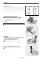
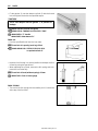
THROTTLE CABLE PLAY
Inspect initially at 1 000 km (5 months) and every
4 000 km (20 months) thereafter.
Adjust the throttle cable play A with the following procedures.
• Loosen the lock-nut 1 of the throttle cable.
• Turn the adjuster 2 in or out until the throttle cable play A
should be 2.0 – 4.0 mm at the throttle grip.
• Tighten the lock-nut 1 while holding the adjuster 2.
Throttle cable play A: 2.0 – 4.0 mm
&
After the adjustment is completed, check that handlebar movement does not raise the engine idle speed
and that the throttle grip returns smoothly and automatically.
NOTE:
Major adjustment can be made by the carburetor side adjuster.
http://www.motorcycle.in.th
PERIODIC MAINTENANCE
DRIVE BELT
Inspect every 4 000 km (20 months) thereafter.
• Keep the motorcycle upright.
• Remove the clutch cover. (!3-10)
• Check the contact surface for crack or other damage. If crack
or other damage exists, replace the belt with a new one.
"
If grease or oil is present on the surface, decrease the
belt thoroughly.
• Install the clutch cover. (!3-72)
NOTE:
Drain water from the clutch cover by removing the drain bolt A.
REDUCTION GEAR BOX OIL
Inspect every 8 000 km (40 months) thereafter.
• Keep the motorcycle upright.
• Place an oil pan below the gear case, and drain oil by removing the oil drain plug 1 and filler cap 2.
• Tighten the drain plug 1, and pour fresh oil through the oil
filler.
Oil viscosity and classification: SAE 10W-40 with SF or SG
NECESSARY AMOUNT OF REDUCTION GEAR OIL
Oil change: 100 ml
Overhaul: 110 ml
http://www.motorcycle.in.th
2-11
2-12
PERIODIC MAINTENANCE
BRAKE
Inspect initially at 1 000 km (5 months) and every
4 000 km (20 months) thereafter.
BRAKE LEVER PLAY
• Adjust the brake lever play by turning the adjusting nut 1 so
that the play A is 15 – 25 mm as shown.
# Brake lever play A: 15 – 25 mm
FRONT BRAKE PADS (UY125S)
The extent of brake pad wear can be checked by observing the
grooved limit line A on the brake pad. When the wear exceeds
the grooved limit line, replace the pads with new ones.
(!5-25)
"
Replace the brake pads as a set, otherwise braking
performance will be adversely affected.
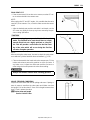
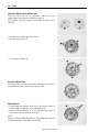
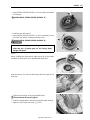
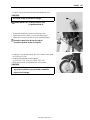
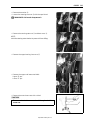
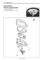
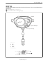
BRAKE SHOW WEAR
This motorcycle is equipped with the brake lining wear limit indicator on the brake.
To check wear of the brake lining, perform the following steps:
• First, check if the brake system is properly adjusted.
• While operating the brake, check to see that the tip of indicator 1 is within the range 2 on the brake panel.
• If the tip of indicator 1 is beyond the range, the brake shoe
assembly should be replaced with a new set of shoe.
(!5-13 and -49)
http://www.motorcycle.in.th
PERIODIC MAINTENANCE
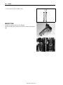
BRAKE HOSE AND BRAKE FLUID (UY125S)
Inspect every 4 000 km (20 months).
Replace hoses every 4 years. Replace fluid every 2
years.
BRAKE HOSE
Check the brake hose for leakage, cracks, wear and damage. If
any damages are found, replace the brake hose with a new one.
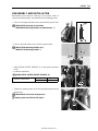
BRAKE FLUID LEVEL CHECK
• Keep the motorcycle upright and place the handlebars
straight.
• Check the brake fluid level relative to the lower limit lines on
the front brake fluid reservoirs.
• When the level is below the lower limit line, replenish with
brake fluid that meets the following specification.
' Specification and classification: DOT 4
&
* The brake system of this motorcycle is filled with a
glycol-based brake fluid. Do not use or mix different
types of fluid such as silicone-based and petroleum-based fluids. Do not use any brake fluid taken
from old, used or unsealed containers. Never re-use
brake fluid left over from the last servicing or stored
for a long period of time.
* Brake fluid, if it leaks, will interfere with safe running
and immediately discolor painted surfaces. Check
the brake hoses and hose joints for cracks and fluid
leakage before riding.
http://www.motorcycle.in.th
2-13
2-14
PERIODIC MAINTENANCE
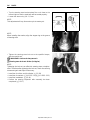
FRONT BRAKE FLUID REPLACEMENT
• Remove the handlebar cover. (!5-5)
• Place the motorcycle on a level surface and keep the handlebar straight.
• Remove the front master cylinder reservoir cap and diaphragm.
• Suck up the old brake fluid as much as possible.
• Fill the reservoir with new brake fluid.
' Specification and classification: DOT 4
• Connect a clear hose 1 to the air bleeder valve and insert the
other end of the hose into a receptacle.
• Loosen the air bleeder valve and pump the brake lever until
the old brake fluid is completely out of the brake system.
• Close the air bleeder valve and disconnect the clear hose. Fill
the reservoir with new brake fluid to the upper end of the
inspection window.
% Air bleeder valve: 7.5 N·m (0.75 kgf-m)
AIR BLEEDING FOR THE FRONT BRAKE FLUID CIRCUIT
Air trapped in the fluid circuit acts like a cushion to absorb a
large proportion of the pressure developed by the master cylinder and thus interferes with the full braking performance of the
brake caliper. The presence of air is indicated by “sponginess”
of the brake lever and also by lack of braking force. Considering
the danger to which such trapped air exposes the machine and
rider, it is essential that, after remounting the brake and restoring the brake system to the normal condition, the brake fluid circuit be purged of air in the following manner:
• Fill up the master cylinder reservoir to the “UPPER” line.
Place the reservoir cap to prevent entry of dirt.
• Connect a clear hose 1 to the air bleeder valve, and insert
the free end of the pipe into a receptacle.
• Front brake: Bleed the air from the air bleeder valve.
http://www.motorcycle.in.th
PERIODIC MAINTENANCE
• Squeeze and release the brake lever several times in rapid
succession and squeeze the lever fully without releasing it.
Loosen the bleeder valve by turning it a quarter of a turn so
that the brake fluid runs into the receptacle; this will remove
the tension of the brake lever causing it to touch the handlebar grip. Then, close the valve, pump and squeeze the lever,
and open the valve.
Repeat this process until the fluid flowing into the receptacle no
longer contains air bubbles.
NOTE:
Replenish the brake fluid in the reservoir as necessary while
bleeding the brake system. Make sure that there is always some
fluid visible in the reservoir.
• Close the bleeder valve, and disconnect the clear hose.
% Air bleeder valve: 7.5 N·m (0.75 kgf-m)
Fill the reservoir with brake fluid to the “UPPER” line.
"
Handle brake fluid with care: the fluid reacts chemically with paint, plastics, rubber materials and so on.
TIRE AND WHEELS
TIRE TREAD CONDITION
Inspect every 4 000 km (20 months).
Operating the motorcycle with excessively worn tires will
decrease riding stability and consequently invite a dangerous
situation. It is highly recommended to replace a tire when the
remaining depth of the tire tread reaches the following specification.
$ 09900-20805: Tire depth gauge
# Tire tread depth:
Service Limit: FRONT: 1.6 mm
REAR: 1.6 mm
http://www.motorcycle.in.th
2-15
2-16
PERIODIC MAINTENANCE
TIRE PRESSURE
If the tire pressure is too high or too low, steering will be
adversely affected and tire wear will increase. Therefore, maintain the correct tire pressure for good roadability and a longer
tire life. Cold inflation tire pressure is as follows.
COLD INFLATION
TIRE PRESSURE
FRONT
REAR
kPa
kgf/cm2
175
225
1.75
2.25
"
The standard tire fitted on this motorcycle is a 70/
90-14M/C 34P for the front and a 80/90-14M/C 40P for
the rear. The use of tires other than those specified
may cause instability. It is highly recommended to use
the specified tires.
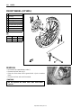
WHEEL
Make sure that the wheel runout (axial and radial) does not
exceed the service limit when checked as shown. An excessive
amount of runout is usually due to worn or loose wheel bearings
and can be corrected by replacing the bearings. If bearing
replacement fails to reduce the runout, replace the wheel.
# Wheel runout
Service Limit (axial and radial): 2.0 mm
SPOKE NIPPLES
Make sure that the nipples are tight. If necessary, tighten them
with a spoke nipple wrench.
% Spoke nipple: 4.5 N·m (0.45 kgf-m)
$ 09940-60113: Spoke nipple wrench
http://www.motorcycle.in.th
PERIODIC MAINTENANCE
STEERING
Inspect initially at 1 000 km (5 months) and every
8 000 km (40 months) thereafter.
The steering should be adjusted properly for smooth turning of
handlebars and safe operation. Overtight steering prevents
smooth turning of the handlebars and too loose steering will
cause poor stability. Check that there is no play in the front fork.
Support the motorcycle so that the front wheel is off the ground.
With the wheel facing straight ahead, grasp the lower fork tubes
near the axle and pull forward. If play is found, readjust the
steering. (!5-46)
FRONT FORK
Inspect every 8 000 km (40 months).
Inspect the front forks for oil leakage, scoring or scratches on
the outer surface of the inner tubes. Replace any defective
parts, if necessary. (!5-34)
REAR SUSPENSION
Inspect every 8 000 km (40 months).
Inspect the rear shock absorber for oil leakage and mounting
rubbers including engine mounting for wear and damage.
Replace any defective parts, if necessary. (!5-53)
http://www.motorcycle.in.th
2-17
2-18
PERIODIC MAINTENANCE
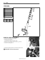
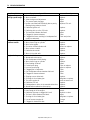
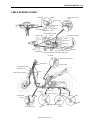
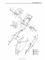
CHASSIS BOLTS AND NUTS
Tighten initially at 1 000 km (5 months) and every 4 000 km (20 months) thereafter.
Check that all chassis bolts and nuts are tightened to their specified torque. (Refer to page 2-19 for the locations of the following bolts and nuts on the motorcycle.)
ITEM
1
2
3
4
5
6
7
8
9
0
A
B
C
D
E
F
Handlebar clamp bolt
Steering stem lock-nut
Front fork clamp bolt
Front fork cap bolt
Front axle nut
Engine mounting nut
Rear axle nut
Front brake caliper mounting bolt (UY125S)
Front brake hose union bolt (UY125S)
Front brake disc bolt (UY125S)
Air breeder valve (UY125S)
Front brake master cylinder bolt (UY125S)
Rear shock absorber mounting nut (Upper & Lower)
Front brake cam lever nut (UY125)
Rear brake cam lever nut
Spoke nipple
http://www.motorcycle.in.th
N·m
60
90
28
33
42
85
120
25
23
23
7.5
10
29
8
11
4.5
kgf-m
6.0
9.0
2.8
3.3
4.2
8.5
12.0
2.5
2.3
2.3
0.75
1.0
2.9
0.8
1.1
0.45
PERIODIC MAINTENANCE
http://www.motorcycle.in.th
2-19
2-20
PERIODIC MAINTENANCE
COMPRESSION PRESSURE CHECK
The compression pressure reading of a cylinder is a good indicator of its internal condition.
The decision to overhaul the cylinder is often based on the results of a compression test. Periodic maintenance records kept at your dealership should include compression readings for each maintenance service.
COMPRESSION PRESSURE SPECIFICATION
Standard
750 – 1 200 kPa
(7.5 – 12 kgf/cm²)
Limit
650 kPa
(6.5 kgf/cm²)
Low compression pressure can indicate any of the following conditions:
* Excessively worn cylinder walls
* Worn piston or piston rings
* Piston rings stuck in grooves
* Poor valve seating
* Ruptured or otherwise defective cylinder head gasket
NOTE:
When the compression pressure goes below specification, check the engine for conditions listed above.
COMPRESSION TEST PROCEDURE
NOTE:
* Before testing the engine for compression pressure, make
sure that the cylinder head nuts are tightened to the specified
torque values and the valves are properly adjusted.
* Warm up the engine before testing.
* Make sure that the battery is fully-charged.
Remove the related parts and test the compression pressure in
the following manner:
• Remove the spark plug. (!2-7)
• Install the compression gauge and adaptor in the spark plug
hole. Make sure that the connection is tight.
• Keep the throttle grip in the fully opened position.
• Press the starter button and crank the engine for a few seconds. Record the maximum gauge reading as the cylinder
compression.
$ 09915-64512: Compression gauge
09915-63311: Adaptor
http://www.motorcycle.in.th
PERIODIC MAINTENANCE
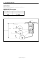
OIL PRESSURE CHECK
Check the oil pressure periodically. This will give a good indication of the condition of the moving parts.
OIL PRESSURE SPECISFICATION
18 – 40 kPa (0.18 – 0.40 kgf/cm²) at 3 000 rpm, Oil temp. at 60 °C.
If the oil pressure is lower or higher than specification, the following causes may be considered.
LOW OIL PRESSURE
* Clogged oil filter
* Oil leakage from the oil passage
* Damaged O-ring
* Defective oil pump
* Combination of the above items
HIGH OIL PRESSURE
* Engine oil viscosity is too high
* Clogged oil passage
* Combination of the above items
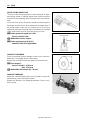
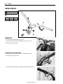
OIL PRESSURE TEST PROCEDURE
• Connect a tachometer to the high-tension cord.
• Remove the main oil gallery plug 1.
• Install the oil pressure gauge and adaptor into the main oil
gallery.
• Warm up the engine as follows:
Summer: 10 minutes at 2 000 rpm
Winter: 20 minutes at 2 000 rpm
• After warming up the engine, increase the engine speed to
3 000 rpm (observe the tachometer), and read the oil pressure gauge.
$ 09915-74511: Oil pressure gauge
09915-74531: Adaptor
09900-26006: Tachometer
% Main gallery plug: 12 N·m (1.2 kgf-m)
http://www.motorcycle.in.th
2-21
2-22
PERIODIC MAINTENANCE
AUTOMATIC CLUTCH INSPECTION
This motorcycle is equipped with an automatic clutch and variable ratio belt drive transmission. The engagement of the clutch
is governed by engine RPMs and centrifugal mechanism located
in the clutch.
To insure proper performance and longer lifetime of the clutch
assembly it is essential that the clutch engages smoothly and
gradually. The following inspections must be performed:
1. INITIAL ENGAGEMENT INSPECTION
•
•
•
•
Warm up the engine to normal operating temperature.
Remove the front frame cover. (!5-8)
Connect an electric tachometer to the high-tension cord.
Seated on the motorcycle with the motorcycle on level
ground, increase the engine RPM slowly and note the RPM at
which the motorcycle begins to move forward.
$ 09900-26006: Tachometer
Engagement rpm: 2 900 – 3 500 rpm
2. CLUTCH “LOCK-UP” INSPECTION
Perform this inspection to determine if the clutch is engaging
fully and not slipping.
• Apply the front and rear brakes as firm as possible.
• Briefly open the throttle fully and note the maximum engine
RPMs sustained during the test cycle.
"
Do not apply full power for more than x seconds or
damage to the clutch or engine may occur.
Lock-up rpm: 4 500 – 5 500 rpm
http://www.motorcycle.in.th
ENGINE
3-1
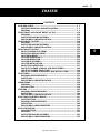
ENGINE
CONTENTS
ENGINE COMPONENTS REMOVABLE WITH THE ENGINE IN PLACE ..
ENGINE REMOVAL AND INSTALLATION .................................................
ENGINE REMOVAL...............................................................................
ENGINE REMOUNTING ........................................................................
ENGINE DISASSEMBLY .............................................................................
ENGINE COMPONENT INSPECTION AND SERVICE ...............................
CYLINDER HEAD COVER ....................................................................
CYLINDER HEAD ..................................................................................
CYLINDER .............................................................................................
PISTON ..................................................................................................
CRANKSHAFT ......................................................................................
OIL PUMP ..............................................................................................
MOVABLE DRIVE FACE.......................................................................
CLUTCH SHOE/MOVABLE DRIVEN FACE .........................................
DRIVE BELT ..........................................................................................
DRIVE BELT FILTER ............................................................................
STARTER CLUTCH...............................................................................
MAGNETO COVER ...............................................................................
KICK STARTER.....................................................................................
REDUCTION GEAR...............................................................................
BEARING INSPECTION ........................................................................
RIGHT CRANKCASE ............................................................................
ENGINE MOUNTING BUSHING ...........................................................
LEFT CRANKCASE ..............................................................................
ENGINE MOUNTING BUSHINGS .........................................................
CRANKSHAFT SHIM SELECTION .......................................................
ENGINE REASSEMBLY ..............................................................................
PAIR (AIR SUPPLY) SYSTEM.....................................................................
PAIR HOSES INSPECTION ..................................................................
PAIR REED VALVE INSPECTION ........................................................
PAIR CONTROL VALVE INSPECTION ................................................
http://www.motorcycle.in.th
3- 2
3- 4
3- 4
3- 8
3-10
3-20
3-20
3-21
3-33
3-34
3-36
3-37
3-37
3-39
3-44
3-44
3-45
3-46
3-47
3-49
3-51
3-51
3-51
3-52
3-54
3-55
3-56
3-73
3-73
3-73
3-73
3
3-2
ENGINE
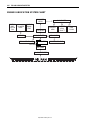
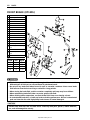
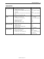
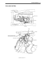
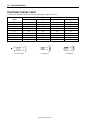
ENGINE COMPONENTS REMOVABLE WITH THE ENGINE IN PLACE
The parts listed below can be removed and reinstalled without removing the engine from the frame. Refer to
page listed in each section for removal and reinstallation instructions.
ENGINE CENTER
PARTS
Starter motor
Cylinder head cover
Camshaft
Camshaft sprocket
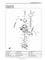
Carburetor
Cam chain tension adjuster
PAIR cut valve
Cylinder head
Cylinder
Piston
Intake pipe
Crankcase tube grommet
REMOVAL
!3-10
!3-11
!3-22
!3-12
!3-4
!3-12
!3-11
!3-12
!3-12
!3-13
!3-11
!3-10
INSTALLATION
!3-71
!3-70
!3-32
!3-68
!4-8
!3-69
!3-71
!3-67
!3-67
!3-66
!3-71
!3-72
REMOVAL
!3-17
!3-17
!3-17
!3-17
!3-17
!3-18
!3-19
!3-49
!3-5
!3-11
!3-18
!3-10
!3-44
!3-10
!3-11
!3-18
!3-6
INSTALLATION
!3-61
!3-60
!3-60
!3-60
!3-60
!3-59
!3-57
!3-59
—
!2-7
!3-58
!3-72
!3-45
!3-72
!3-71
!3-59
—
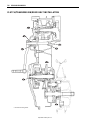
ENGINE LEFT SIDE
PARTS
Fixed drive face
Movable drive face assembly
Clutch housing
Clutch shoe/movable driven face assembly
Drive belt
Reduction gear cover
Oil sump filter
Drive shaft
Air cleaner box
Spark plug
Oil filter
Kick starter lever
Cooling belt cover and duct
Clutch cover
Cylinder cowling left cover
Idle driven gear
Clutch upper cover and crankcase tube
http://www.motorcycle.in.th
ENGINE
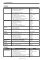
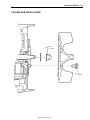
ENGINE RIGHT SIDE
PARTS
Muffler
Fan cowling cover
Cooling fan
Starter idle gear
Magneto cover
Magnetorotor
Oil pump
Cylinder cowling right cover
REMOVAL
!3-5
!3-11
!3-13
!3-15
!3-14
!3-15
!3-16
!3-11
http://www.motorcycle.in.th
INSTALLATION
!3-9
!3-71
!3-65
!3-63
!3-63
!3-62
!3-61
!3-71
3-3
3-4
ENGINE
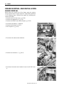
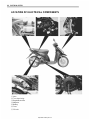
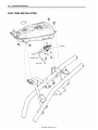
ENGINE REMOVAL AND INSTALLATION
ENGINE REMOVAL
Before taking the engine out of the frame, wash the engine
using a steam cleaner. Engine removal is sequentially explained
in the following steps. Reinstall the engine by reversing the
removal procedure.
• Remove the front frame cover. (!5-8)
• Remove the luggage box. (!5-9)
• Remove the frame covers (left and right). (!5-10)
• Disconnect the battery - lead wire.
• Remove the fuel tank. (!4-2)
• Drain engine oil. (!2-8)
• Disconnect the starter motor lead wire.
• Remove the carburetor 1. (!4-8)
• Disconnect the head cover breather hose 2 and PAIR hose
3.
http://www.motorcycle.in.th
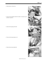
ENGINE
• Remove the air cleaner box.
• Disconnect the magneto lead wire coupler 4 and pick-up coil
lead wire coupler 5.
• Remove the engine ground bolt.
• Disconnect the spark plug cap 6.
• Remove the exhaust pipe bolts.
http://www.motorcycle.in.th
3-5
3-6
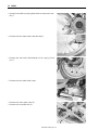
ENGINE
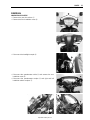
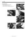
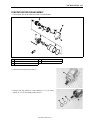
• Remove the muffler mounting bolts and then remove the muffler 7.
• Remove the rear brake cable clamp bracket 8.
• Remove the rear brake cable adjuster nut 9, spring 0 and
pin A.
• Remove the rear brake cable clamp.
• Remove the clutch upper cover B.
• Remove the crankcase tube C.
http://www.motorcycle.in.th
ENGINE
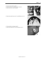
• Support the engine using a jack.
• Remove the rear shock absorber lower mounting bolt.
• Remove the engine mounting bolt and nut.
NOTE:
Never remove the crankcase bracket D from the frame.
• Remove the engine from the frame.
http://www.motorcycle.in.th
3-7
3-8
ENGINE
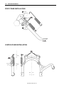
ENGINE REMOUNTING
Remount the engine in the reverse order of removal. Pay attention to the following points:
• Install the crankcase bracket 1 to the frame and insert the
crankcase bracket mounting shaft.
• Push up on the rear part of the crankcase bracket 1 and
have the damper B touch the stopper A. While holding the
damper, tighten the engine mounting bracket nut 2 to the
specified torque.
" Crankcase bracket nut: 102 N·m (10.2 kgf-m)
• Install the engine and tighten the engine mounting nut 3 to
the specified torque.
" Engine mounting nut: 85 N·m (8.5 kgf-m)
NOTE:
When tightening the engine mounting nut, make sure that the
front wheel is elevated.
• Tighten the rear shock absorber lower mounting nut 4 to the
specified torque.
" Rear shock absorber mounting bolt: 29 N·m (2.9 kgf-m)
NOTE:
* Place 65 kg on the seat, after installing the engine.
* Check that clearance C and D are equal. If clearances C and
D are not equal, repeat the engine installation procedures.
• Install the crank case tube 5.
NOTE:
Set the crankcase tube E to the crankcase tube grommet F.
(!7-23)
http://www.motorcycle.in.th
ENGINE
• Install the muffler.
#
Replace the gasket with new one.
• After installing the engine, properly route the wire harness,
cables, and hoses. Refer to the wire and cable routing sections. (!7-12 to -19)
• Refer to the following sections to adjust the respective items
to specification.
* ENGINE OIL (!2-8)
* REDUCTION GEAR OIL (!2-11)
* THROTTLE CABLE PLAY (!2-10)
* ENGINE IDLE SPEED (!2-10)
* REAR BRAKE CABLE ADJUSTMENT (!2-12)
• Check for leakage of the engine oil and reduction gear oil.
http://www.motorcycle.in.th
3-9
3-10
ENGINE
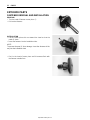
ENGINE DISASSEMBLY
#
Identify the position of each removed part. Organize
the parts in their respective groups so that they can be
reinstalled in their original positions.
CLUTCH COVER
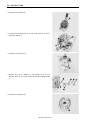
• Remove the kick starter lever.
• Remove the clutch cover assembly 1.
CRANKCASE TUBE GROMMET
• Remove the crankcase tube grommet No.1 1 and No.2 2.
STARTER MOTOR
• Remove the starter motor 1.
http://www.motorcycle.in.th
ENGINE
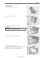
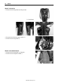
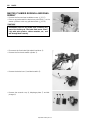
PAIR CUT VALVE
• Disconnect the PAIR hose 1 and vacuum hose 2.
• Remove the PAIR cut valve 3.
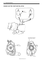
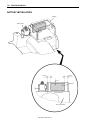
FAN COWLING COVER/CYLINDER COWLING/INTAKE PIPE
• Remove the fan cowling cover 1 and cylinder cowling right
cover 2.
• Remove the intake pipe 3 and cylinder cowling left cover 4.
SPARK PLUG
• Remove the spark plug.
CYLINDER HEAD COVER
• Remove the cylinder head cover 1 and gasket.
http://www.motorcycle.in.th
3-11
3-12
ENGINE
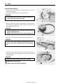
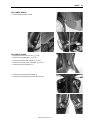
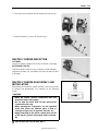
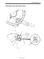
• Turn the crankshaft clockwise with a box wrench and align the
“Top” mark A on the cooling fan with the index mark B on the
magneto cover.
NOTE:
The piston must be at TDC on the compression stroke.
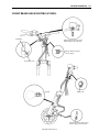
CAM CHAIN TENSION ADJUSTER
• Remove the cam chain tension adjuster 1 and gasket.
CAMSHAFT SPROCKET
• Remove the decompression cam assembly 1 and camshaft
sprocket 2.
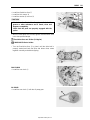
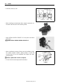
CYLINDER HEAD
• Remove the cylinder head side nuts 1 and cylinder head nuts
2.
• Remove the cylinder head.
NOTE:
* When loosening the cylinder head nuts, loosen each nut little
by little diagonally.
* If the cylinder head does not come off, lightly tap on the finless
portion of it with a plastic hammer.
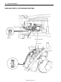
CYLINDER
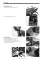
• Remove the dowel pins 1, gasket 2 and cam chain guide 3.
• Remove the cylinder.
NOTE:
If the cylinder does not come off, lightly tap on the finless portion
of it with a plastic hammer.
http://www.motorcycle.in.th
ENGINE
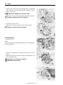
• Remove the dowel pins 4 and gasket 5.
PISTON
• Remove the piston pin circlip.
• Remove the piston by driving out the piston pin.
NOTE:
Place a clean rag over the cylinder base so as not to drop the
piston pin circlip into the crankcase.
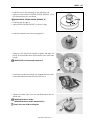
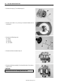
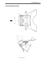
COOLING FAN
• Remove the cooling fan 1.
• Remove the cooling fan holder nut with the special tool.
$ 09930-40113: Rotor holder
• Remove the washer 2 and cooling fan holder 3.
http://www.motorcycle.in.th
3-13
3-14
ENGINE
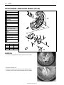
REAR WHEEL/REAR BRAKE
• Remove the rear wheel.
• Remove the brake shoes.
CENTER STAND
• Remove the center stand spring 1.
• Remove the cotter pin 2, washer 3, shaft 4 and center
stand 5.
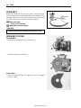
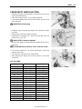
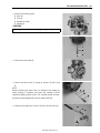
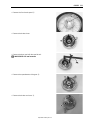
MAGNETO COVER
• Remove the magneto cover 1.
http://www.motorcycle.in.th
ENGINE
• Remove the dowel pins 2 and gasket 3.
STARTER IDLE GEAR
• Remove the starter idle gear 1 and shaft 2.
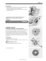
MAGNETOROTOR
• Hold the fixed drive face with the special tool.
$ 09930-40113: Rotor holder
• Remove the magnetorotor nut.
• Remove the magnetorotor 1 with the special tool.
$ 09930-34980: Rotor remover
• Remove the starter clutch 2.
http://www.motorcycle.in.th
3-15
3-16
ENGINE
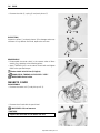
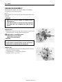
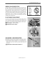
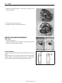
• Remove the key 3.
OIL PUMP
• Remove the oil pump cover 1.
• Turn the oil pump sprocket and align the oil pump sprocket
hole on the oil pump mounting screw 2.
• Remove the oil pump screw 2.
• Remove the oil pump assembly 3 along with the chain 4.
NOTE:
The oil pump assembly is a non-disassemblable type.
• Remove the cam chain 5.
http://www.motorcycle.in.th
ENGINE
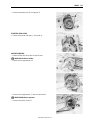
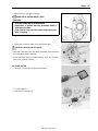
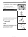
FIXED DRIVE FACE
• Remove the fixed drive face nut with the special tool.
$ 09930-40113: Rotor holder
• Remove the washer 1, kick starter 2 and fixed drive face 3.
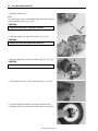
MOVABLE DRIVEN FACE/CLUTCH HOUSING
• Remove the clutch housing nut with the special tool.
$ 09930-40113: Rotor holder
• Remove the clutch hosing 1.
• Remove the clutch shoe/movable driven face assembly 2
along with the drive belt 3.
• Remove the movable drive face assembly 4 and spacer 5.
http://www.motorcycle.in.th
3-17
3-18
ENGINE
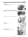
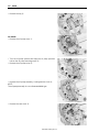
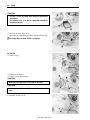
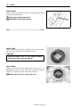
REDUCTION GEAR
• Drain the reduction gear oil. (!2-11)
• Remove the reduction gear cover 1.
• Remove the gasket 2 and dowel pins 3.
• Remove the washer 4, idle driven gear 5 and rear axle shaft
6.
OIL FILTER
• Remove the oil filter cap 1.
• Remove the oil filter 2 and O-ring 3.
http://www.motorcycle.in.th
ENGINE
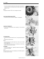
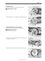
OIL SUMP FILTER
• Remove the oil sump filter cap 1 and oil sump filter 2.
BRAKE CAM LEVER
• Remove the rear brake cam lever 1, brake lining wear indicator 2 and brake cam 3.
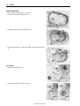
CRANKCASE
• Remove the crankcase bolts.
• Separator the crankcase into 2 parts, right and left with the
crankcase separating tool.
$ 09920-13120: Crankcase separating tool
NOTE:
* Fit the crankcase separating tool, so that the tool arms are in
parallel with the side of crankcase.
* The crankshaft component should remain in the left crankcase
half.
CRANKSHAFT
• Remove the crankshaft with the special tool.
$ 09920-13120: Crankcase separating tool
http://www.motorcycle.in.th
3-19
3-20
ENGINE
ENGINE COMPONENT INSPECTION
AND SERVICE
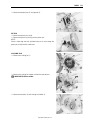
CYLINDER HEAD COVER
DISASSEMBLY
• Remove the PAIR reed valve cover 1 and PAIR reed valve
2.
• Remove the breather cover 3, oil separator 4 and gasket 5.
INSPECTION
REED VALVE
• Inspect the reed valve for the carbon deposit.
• If the carbon deposit is found in the reed valve, replace the
PAIR reed valve with a new one.
OIL SEPARATOR
• Check the oil separator for any damage or clogs.
• If they are clogged, clean the oil separator with a compressed
air or replace.
http://www.motorcycle.in.th
ENGINE
REASSEMBLY
• Reassembly the cylinder head cover in the reverse order of
disassembly. Pay attention to the following points:
• Install the breather cover gasket 1.
#
Replace the removed breather gasket with a new one.
• Tighten the breather cover bolts to the specified torque.
" Breater cover bolt: 10 N·m (1.0 kgf-m)
• Apply THREAD LOCK to the PAIR reed valve cover bolts and
tighten them.
% 99000-32050: THREAD LOCK “1342”
CYLINDER HEAD
#
Identify the position of each removed part. Organize
the parts in their respective groups (i.e., intake or
exhaust) so that they can be installed in their original
locations.
DISASSEMBLY
• Remove the cam chain tensioner 1.
• Remove the camshaft retainer 2.
http://www.motorcycle.in.th
3-21
3-22
ENGINE
• Pull out the intake and exhaust rocker arm shafts 3 by using
an 8-mm thread bolt.
• Remove the intake and exhaust rocker arms 4.
• Remove the camshaft 5.
• Compress the valve spring with the valve spring compressor.
• Remove the valve cotters from the valve stem.
$ 09916-14510: Valve spring compressor
09916-14521: Attachment
09916-84511: Tweezers
• Remove the valve spring retainer 6 and valve spring 7.
• Remove the valve 8 from the combustion chamber side.
http://www.motorcycle.in.th
ENGINE
• Remove the valve stem seal 9 and valve spring seat 0.
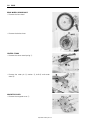
ROCKER ARM SHAFT O.D.
Measure the diameter of rocker arm shaft.
& Rocker arm shaft O.D. (IN. & EX.)
Standard: 9.981 – 9.990 mm
$ 09900-20205: Micrometer (0 – 25 mm)
ROCKER ARM I.D.
When checking the valve rocker arm, the inside diameter of the
valve rocker arm and wear of the camshaft contacting surface
should be checked.
& Rocker arm I.D. (IN. & EX.)
Standard: 10.003 – 10.018 mm
$ 09900-20605: Dial calipers
CYLINDER HEAD DISTORTION
Decarbon the combustion chamber.
Check the gasketed surfaced of the cylinder head for distortion
with a straightedge and thickness gauge, taking a clearance
reading at several places as indicated. If the largest reading at
any position of the straightedge exceeds the limit, replace the
cylinder head.
& Cylinder head distortion
Service Limit: 0.05 mm
$ 09900-20803: Thickness gauge
http://www.motorcycle.in.th
3-23
3-24
ENGINE
VALVE FACE WEAR
The thickness of the valve face decreases as the face wears.
Visually inspect each valve face for wear and replace any valve
with an abnormally worn face. Measure the valve face thickness
T, if it is out of specification, replace the valve with a new one.
& Valve head thickness (IN. & EX.)
Service Limit T: 0.5 mm
$ 09900-20101: Venier calipers
VALVE STEM RUNOUT
Support the valve using V-blocks, as shown, and measure its
runout with the dial gauge. If the runout exceeds the limit,
replace the valve.
& Valve stem runout (IN. & EX.)
Service Limit: 0.05 mm
$ 09900-20701: Magnetic stand
09900-20607: Dial gauge (1/100 mm)
09900-21304: V-block (100 mm)
VALVE HEAD RADIAL RUNOUT
Place the dial gauge at right angles to the valve head, and measure the valve head radial runout.
If it measures more than limit, replace the valve.
& Valve head radial runout (IN. & EX.)
Service Limit: 0.03 mm
$ 09900-20607: Dial gauge (1/100 mm)
09900-20701: Magnetic stand
09900-21304: V-block (100 mm)
VALVE STEM DEFLECTION
Lift the valve about 10 mm from the valve seat. Measure the
valve stem deflection in two directions, “X” and “Y”, perpendicular to each other, by positioning the dial gauge as shown. If the
deflection measured exceeds the limit, then determine whether
the valve or the guide should be replaced with a new one.
& Valve stem deflection
Service Limit (IN. & EX.): 0.35 mm
$ 09900-20607: Dial gauge (1/100 mm)
09900-20701: Magnetic stand
http://www.motorcycle.in.th
ENGINE
VALVE STEM WEAR
If the valve stem is worn down to the limit, when measured with
a micrometer, and the clearance is found to be in excess of the
limit indicated previously, replace the valve, if the stem is within
the limit, then replace the guide. After replacing valve or guide,
be sure to re-check the clearance.
& Valve stem O.D.
Standard (IN.) : 4.975 – 4.990 mm
(EX.): 4.955 – 4.970 mm
$ 09900-20205: Micrometer (0 – 25 mm)
VALVE GUIDE SERVICE
• Remove the valve guide with the valve guide remover.
$ 09916-44310: Valve guide remover
• Re-finish the valve guide holes in cylinder head with the handle and reamer.
$ 09916-34542: Handle
09916-34580: Valve guide reamer (10.8 mm)
• Fit a ring to each valve guide.
• Lubricate each valve guide with oil, and drive the guide into
the guide hole with the special tool.
$ 09916-44310: Valve guide installer
NOTE:
Install the valve guide until the ring A contacts with the cylinder
head.
#
Be sure to use new ring and valve guide.
http://www.motorcycle.in.th
3-25
3-26
ENGINE
• After fitting the valve guides, re-finish their guiding bores with
the handle and reamer. Be sure to clean and oil the guides
after reaming.
$ 09916-34542: Handle
09916-34570: Valve guide reamer (5.0 mm)
VALVE SEAT WIDTH INSPECTION
Visually check for valve seat width on each valve face.
If the valve face has worn abnormally, replace the valve.
Coat the valve seat with Prussian Blue and set the valve in
place.
Rotate the valve with light pressure. Check that the transferred
blue on the valve face is uniform all around and in center of the
valve face.
If the seat width W measured exceeds the standard value, or
seat width is not uniform reface the seat using the seat cutter.
& Valve seat width W
Standard (IN.) : 0.90 – 1.10 mm
(EX.): 0.92 – 1.12 mm
Service Limit: Reface if measurement does not agree
with standard valve.
$ 09916-10911: Valve lapper set
• If either requirement is not met, correct the seat by servicing it
as follows.
http://www.motorcycle.in.th
ENGINE
VALVE SEAT SERVICE
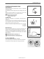
The valve seats 1 for both the intake and exhaust valves are
machined to four different angles. The seat contact surface is
cut at 45°.
45°
15°
30°
INTAKE SIDE
N-122
EXHAUST SIDE
N-122
N-121
For intake
N-126
$ 09916-21111: Valve seat cutter set
09916-20610: Valve seat cutter (N-121)
09916-20620: Valve seat cutter (N-122)
09916-20630: Valve seat cutter (N-126)
09916-24311: Solid pilot (N-100-5.0)
NOTE:
Use the solid pilot (N-100-5.0) along with the valve seat cutter
(N-121, -122 and -126).
For exhaust
#
The valve seat contact area must be inspected after
each cut.
15˚
30˚
• When installing the solid pilot 2, rotate it slightly.
http://www.motorcycle.in.th
45˚
3-27
3-28
ENGINE
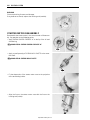
• Seat the pilot snugly. Install the 45° cutter 3, attachment and
T-handle 4.
INITIAL SEAT CUT
• Using the 45° cutter, descale and clean up the seat. Rotate
the cutter one or two turns.
• Measure the valve seat width W after every cut.
45˚
• If the valve seat is pitted or burned, use the 45° cutter to condition the seat some more.
NOTE:
Cut only the minimum amount necessary from the seat to prevent the possibility of the valve stem becoming too close to the
rocker arm for correct valve contact angle.
TOP NARROWING CUT
• If the contact area W is too high on the valve, or if it is too
wide, use the 15° (for exhaust side) and the 30° (for the intake
side) to lower and narrow the contact area.
15˚: For exhaust
30˚: For intake
http://www.motorcycle.in.th
ENGINE
FINAL SEAT CUT
• If the contact area W is too low or too narrow, use the 45° cutter to raise and widen the contact area.
NOTE:
After cutting the 15° and 30° angles, it is possible that the valve
seat (45°) is too narrow. If so, re-cut the valve seat to the correct
width.
• After the desired seat position and width is achieved, use the
45° cutter very lightly to clean up any burrs caused by the previous cutting operations.
#
Do not use lapping compound after the final cut is
made. The finished valve seat should have a velvety
smooth finish but not a highly polished or shiny finish. This will provide a soft surface for the final seating of the valve which will occur during the first few
seconds of engine operation.
45˚
NOTE:
After servicing the valve seats, be sure to check the valve clearance after the cylinder head has been reinstalled. (!2-6)
• Clean and assemble the head and valve components. Fill the
intake and exhaust ports with gasoline to check for leaks. If
any leaks occur, inspect the valve seat and face for burrs or
other things that could prevent the valve from sealing.
'
Always use extreme caution when handling gasoline.
VALVE STEM END CONDITION
Inspect the valve stem end face for pitting and wear. If pitting or
wear is present, resurface the valve stem end. Make sure that
the length A is not less than 2.2 mm. If this length becomes less
than 2.2 mm, replace the valve.
& Valve stem end length
Service Limit: 2.2 mm
http://www.motorcycle.in.th
3-29
3-30
ENGINE
VALVE SPRING INSPECTION
The force of the coil spring keeps the valve seat tight. A weakened spring results in reduced engine power output and often
accounts for the chattering noise coming from the valve mechanism.
Check the valve springs for proper strength by measuring their
free length and also by the force required to compress them. If
the spring length is less than the service limit or if the force
required to compress the spring does not fall within the specified
range, replace both the inner and outer springs as a set.
& Valve spring free length (IN. & EX.)
Service Limit: 32.9 mm
118 N (12.0 kgf)
$ 09900-20102: Vernier calipers
26.8 mm
& Valve spring tension (IN. & EX.)
Standard: 118 N (12.0 kgf)/26.8mm
CAMSHAFT CAM WEAR
Check for abnormal surface damage or wear on the cam face.
Measure the cam height H with a micrometer.
Replace the camshaft if found worn down to the service limit.
& Cam height H
Service Limit (IN.) : 27.62 mm
(EX.) : 27.47 mm
$ 09900-20202: Micrometer (25 – 50 mm)
CAMSHAFT BEARING
Rotate the camshaft bearing outer race by finger to inspect for
abnormal play, noise and smooth rotation.
Replace the bearing in the following procedure if there is anything unusual.
http://www.motorcycle.in.th
ENGINE
• Remove the bearings and cam sprocket flange with a bearing
puller.
$ 09913-60910: Bearing & gear puller
NOTE:
Avoid removing the cam sprocket flange and bearing from the
camshaft unless it is really necessary to do so, for example,
removing the damaged bearing.
#
The removed bearing should be replaced with a new
one.
• Press in the bearings to the camshaft with a bearing installer.
$ 09951-16080: Bearing installer ((49 mm)
09913-70210: Bearing installer ((32 mm)
CAM CHAIN TENSIONER
Inspect the cam chain tensioner for damage. If any damage are
found, replace the cam chain tensioner with a new one.
REASSEMBLY
• Insert the valves, with their stems coated with molybdenum oil
solution all around and along the full stem length without any
break.
Similarly oil the lip of the stem seal.
) MOLYBDNUM OIL SOLUTION
#
When inserting each valve, take care not to damage
the lip of the stem seal.
http://www.motorcycle.in.th
3-31
3-32
ENGINE
• Install the valve spring, making sure that the close-pitch end
A of each spring goes in first to rest on the head. The coil
pitch of spring vary: the pitch decreases from top to bottom,
as shown in the illustration.
Towards
Head
• Put on the valve spring retainer, and using the valve lifter,
press down the spring, fit the cotter halves to the stem end,
and release the lifter to allow the cotter 1 to wedge in
between retainer and stem. Be sure that the rounded lip B of
the cotter fits snugly into the groove C in the stem end.
$ 09916-14510: Valve lifter
09916-14521: Valve lifter attachment
09916-84511: Tweezers
#
Be sure to restore each spring and valve to their original positions.
NOTE:
Just before installing the camshaft into the cylinder head, apply
molybdenum oil solution to the cam faces.
) MOLYBDNUM OIL SOLUTION
• Apply engine oil to the rocker arm shafts, rocker arms and
install them.
http://www.motorcycle.in.th
ENGINE
CAM CHAIN TENSIONER
• Install the cam chain tensioner 1 and washer 2.
• Tighten the cam chain tensioner bolt 3 to the specified
torque.
" Cam chain tensioner bolt: 10 N·m (1.0 kgf-m)
CYLINDER
CYLINDER DISTORTION
Check the gasketed surface of the cylinder for distortion with a
straightedge and thickness gauge, taking a clearance reading at
several places as indicated. If the largest reading at any position
of the straightedge exceeds the limit, replace the cylinder.
& Cylinder distortion
Service Limit: 0.05 mm
$ 09900-20803: Thickness gauge
CYLINDER BORE
• Inspect the cylinder wall for any scratches, nicks or other
damage.
• Measure the cylinder bore diameter at six places.
& Cylinder bore
Service Limit: 53.610 mm
$ 09900-20530: Cylinder bore gauge set
CAM CHAIN TENSION ADJUSTER
Make sure the push rod movement. If the push rod is stuck or
spring mechanism failed, replace the cam chain tension adjuster
assembly with a new one.
CAM CHAIN GUIDE
Inspect the cam chain guide for damage. If any damage are
found, replace the cam chain guide with a new one.
http://www.motorcycle.in.th
3-33
3-34
ENGINE
PISTON
PISTON DIAMETER
Using a micrometer, measure the piston outside diameter at the
place 10 mm from the skirt end as shown. If the measurement is
less than the limit, replace the piston.
& Piston diameter
Service Limit: 53.380 mm
10 mm
$ 09900-20203: Micrometer (50 – 75 mm)
PISTON-TO-CYLINDER CLEARANCE
• Subtract the piston diameter from the cylinder bore diameter.
(!3-33)
• If the piston-to-cylinder clearance exceeds the service limit,
replace the crankcase set or the piston, or both.
& Piston to cylinder clearance
Service Limit: 0.120 mm
PISTON RING-TO-GROOVE CLEARANCE
• Measure the side clearances of the 1st and 2nd piston rings
using the thickness gauge.
• If any of the clearances exceeds the limit, replace both the
piston and piston rings.
& Piston ring-to-groove clearance
Service Limit (1st) : 0.180 mm
(2nd): 0.150 mm
& Piston ring groove width
Standard (1st) : 1.01 – 1.03 mm
(2nd): 1.01 – 1.03 mm
(Oil) : 2.01 – 2.03 mm
& Piston ring thickness
Standard (1st & 2nd): 0.97 – 0.99 mm
$ 09900-20205: Micrometer (0 – 25 mm)
09900-20803: Thickness gauge
NOTE:
Using a soft-metal scraper, decarbon the crown of the piston.
Clean the ring grooves similarly.
http://www.motorcycle.in.th
ENGINE
PISTON RING END GAP
• Measure the piston ring end gap using the vernier calipers.
• Next, fit the piston ring squarely into the cylinder and measure
the piston ring end gap using the thickness gauge.
• If any of the measurements exceeds the service limit, replace
the piston ring with a new one.
$ 09900-20102: Vernier calipers
& Piston ring end gap
Service Limit (1st) : 0.50 mm
(2nd): 0.50 mm
$ 09900-20803: Thickness gauge
PISTON PIN AND PIN BORE
• Measure the piston pin bore diameter using the small bore
gauge.
• If the measurement is out of specification, replace the piston.
& Piston pin bore I.D.
Service Limit: 14.038 mm
$ 09900-20602: Dial gauge (1/1000 mm)
09900-22401: Small bore gauge (10 – 18 mm)
• Measure the piston pin outside diameter at three positions
using the micrometer.
• If any of the measurements is out of specification, replace the
piston pin.
& Piston pin O.D.
Service Limit: 13.980 mm
$ 09900-20205: Micrometer (0 – 25 mm)
http://www.motorcycle.in.th
3-35
3-36
ENGINE
CRANKSHAFT
CONROD SMALL END I.D.
Using a caliper gauge, measure the conrod small end inside
diameter.
& Conrod small end I.D.
Service Limit: 14.064 mm
$ 09900-20605: Dial calipers
If the conrod small end bore inside diameter exceeds the limit,
replace the conrod.
CONROD DEFLECTION AND CONROD BIG END SIDE
CLEARANCE
Wear on the big end of the conrod can be estimated by checking
the movement of the small end of the rod. This method can also
check the extent of wear on the parts of the conrod’s big end.
& Conrod deflection
Service Limit: 3.0 mm
$ 09900-20701: Magnetic stand
09900-20607: Dial gauge (1/100 mm)
09900-21304: V-block
Push the big end of the conrod to one side and measure the
side clearance using a thickness gauge.
& Conrod big end side clearance
Service Limit: 1.0 mm
$ 09900-20803: Thickness gauge
If the clearance exceeds the service limit, replace crankshaft
assembly or bring the deflection and side clearance into specification by replacing the worn parts. (e.g., conrod, big end bearing
and crank pin)
CRANKSHAFT RUNOUT
• Measure the crankshaft runout with V-blocks and dial gauge.
& Crankshaft runout
Service Limit: 0.08 mm
$ 09900-20607: Dial gauge (1/100 mm)
09900-20701: Magnetic stand
09900-21304: V-block
NOTE:
* Place the crankshaft onto the V-blocks so that it becomes horizontally.
* Measure the runout from the tips of the crankshaft.
http://www.motorcycle.in.th
ENGINE
REASSEMBLY
• When rebuilding the crankshaft, the width between the weds
A should be within the standard range.
& Crank wed to wed width A: 48.9 – 49.1 mm
OIL PUMP
DISASSEMBLY
• Remove the circlip 1, washer 2, oil pump driven gear 3 and
pin 4.
INSPECTION
Rotate the oil pump shaft by finger to inspect for abnormal play,
noise and smooth rotation.
If there is anything unusual, replace the oil pump.
#
Do not attempt to disassemble the oil pump assembly.
It is available only as an assembly.
REASSEMBLY
• Reassemble the oil pump driven gear in the reverse order of
disassembly.
• When installing a new circlip, pay attention to the direction of
the circlip. Fit it to the side where the thrust is as shown in the
illustration.
Thrust
Sharp edge
MOVABLE DRIVE FACE
SPACER INSPECTION
• Remove the spacer.
Check the spacer for any damage or wear.
If any defects are found, replace the spacer with a new one.
http://www.motorcycle.in.th
3-37
3-38
ENGINE
MOVABLE DRIVE FACE INSPECTION
Check the drive face for any abnormal condition such as
stepped wear or discoloration caused by burning.
If any defects are found, replace the movable drive face with a
new one.
• Remove the movable drive face plate 1.
• Remove the dampers 2.
• Pull out the six rollers 3.
ROLLER INSPECTION
Check that there is no abnormal wear or damage on the roller. If
any defects are found, replace the rollers as a set.
REASSEMBLY
• Reassemble the movable drive face in the reverse order of
disassembly. Pay attention to the following points:
• Mount the three dampers 1 on the movable drive plate 2
and install it onto the movable drive face.
NOTE:
Make sure the movable drive plate is fully positioned inside the
movable drive face or the rollers may fall out.
http://www.motorcycle.in.th
ENGINE
CLUTCH SHOE/MOVABLE DRIVEN FACE
DISASSEMBLY
• Loosen the clutch shoe nut with the special tool.
$ 09930-40113: Rotor holder
09930-40120: Rotor holder attachment (A)
#
Do not remove the clutch shoe nut at this time.
• Lock the clutch shoe assembly with the special tool handle
turned in.
• Remove the clutch shoe nut 1.
$ 09922-31430: Clutch spring compressor
#
Since a high spring force applies to the clutch shoe
assembly, care must be used so as not to cause the
clutch shoe assembly and movable driven face to
come off abruptly.
• Loosen the special tool handle slowly and remove the clutch
shoe assembly.
#
Do not attempt to disassemble the clutch shoe assembly.
1 Nut
2 Clutch shoe assembly
3 Spring
• Remove the movable driven face seat 4 with a thin blade
screwdriver.
http://www.motorcycle.in.th
3-39
3-40
ENGINE
• Remove the pins 5, movable driven face 6, and fixed driven
face 7.
• Remove the bearing with the special tool.
$ 09921-20240: Bearing remover set
#
The removed bearing should be replaced with a new
one.
• Remove the snap ring.
• Remove the bearing with the special tool.
$ 09913-70210: Bearing remover
#
The removed bearing should be replaced with a new
one.
• Remove the oil seals 8 and O-rings 9.
#
The removed oil seals and O-rings should be replaced
with new ones.
http://www.motorcycle.in.th
ENGINE
CLUTCH SHOES INSPECTION
Inspect the clutch shoes for chips, cracks, uneven wear and
burning. Check the thickness of the shoes using vernier calipers.
If any damages are found or if the thickness is less than the service limit, replace the clutch shoe assembly.
$ 09900-20101: Vernier calipers
& Clutch shoe thickness
Service Limit: 2.5 mm
Inspect the clutch springs for stretched or broken coils. If any
damages are found, replace the clutch shoe assembly.
#
Replace the clutch shoe assembly.
Inspect the clutch housing surface for scrolling, cracks, or
uneven wear and measure the inside diameter of the clutch
housing with inside calipers. Measure the diameter at several
points to check for out-of-round and wear. If any damages are
found or if the inside diameter exceeds the service limit, replace
the clutch housing with a new one.
& Clutch housing l.D.
Service Limit: 125.5 mm
DRIVEN FACE SPRING INSPECTION
Measure the free length of the driven face spring. If the length is
shorter than the service limit, replace the spring with a new one.
& Driven face spring length
Service Limit: 99.8 mm
DRIVEN FACE PINS INSPECTION
Rotate the driven faces and make sure they turn smoothly.
If they stick or do not turn smoothly, inspect the sliding pins 1
for wear or damage. If any damages are found, replace the
driven face with a
new one.
http://www.motorcycle.in.th
3-41
3-42
ENGINE
DRIVEN FACE INSPECTION
Inspect the drive belt contacting surface of both driven faces for
any scratches, wear or damage. If any damages are found,
replace the driven faces with new ones.
REASSEMBLY
Reassemble the clutch shoe assembly and movable driven face
in the reverse order of disassembly. Pay attention to the following points.
• Install the bearing 2 in the fixed driven face 1 with the special tool.
$ 09943-88211: Bearing installer
• Apply SUZUKI SUPER GREASE “A” to the bearing 2.
* 99000-25010: SUZUKI SUPER GREASE “A”
• Securely install the snap ring.
• Install the bearing with the special tool.
$ 09924-84510: Bearing installer
NOTE:
Face the stamped side of the bearing out.
• Apply SUZUKI SUPER GREASE “A” between the sliding surface of the fixed driven face and movable driven face.
* 99000-25010: SUZUKI SUPER GREASE “A”
NOTE:
When installing the movable face to the fixed face, make sure
the oil seal is positioned properly.
http://www.motorcycle.in.th
ENGINE
• Install the pins 3 at three places on the drive face hub.
• Apply as small amount of SUZUKI SUPER GREASE “A” to
the cam where the pins are placed.
* 99000-25010: SUZUKI SUPER GREASE “A”
• Install the new O-rings 4.
• Apply SUZUKI SUPER GREASE “A” to the O-rings.
• Install the movable driven face spring guide 5.
• Slowly turn the special tool handle to tighten and align the
flats A at the movable driven face end with clutch shoe plate
hole B.
$ 09922-31430: Clutch spring compressor
• Check that the special tool dogs are engaged with the clutch
shoe plate holes and screw the clutch shoe nut 6.
• Tighten the clutch shoe nut to the specified torque with the
special tool.
$ 09930-40113: Rotor holder
09930-40120: Rotor holder attachment (A)
" Clutch shoe nut: 60 N·m (6.0 kgf-m)
http://www.motorcycle.in.th
3-43
3-44
ENGINE
DRIVE BELT
Remove the drive belt and check for cracks, wear and separation and measure the drive belt width with vernier calipers. If any
damages are found or if the width of the drive belt is less than
the service limit, replace the drive belt with a new one.
& Drive belt width
Service Limit: 18.9 mm
$ 09900-20101: Vernier calipers
#
Always keep the drive belt away from grease, oil, etc.
DRIVE BELT FILTER
DISASSEMBLY
• Remove the cooling belt cover 1 and duct 2.
• Remove the plate 3 and filter 4.
INSPECTION
• Check the drive belt filter for clogging. If they are clogged,
clean or replace.
http://www.motorcycle.in.th
ENGINE
REASSEMBLY
• Reassemble the drive belt filter in the reverse order of disassembly. Pay attention to the following points:
• Install the plate after aligning the cooling belt cover holes A
with the plate pins B.
• Apply grease to the new O-ring and install the duct 1.
* 99000-25010: SUZUKI SUPER GREASE “A”
#
Use the new O-ring to prevent oil leakage.
STARTER CLUTCH
INSPECTION OF STARTER CLUTCH OPERATION
Turn the starter clutch gear by hand in the direction of arrow as
shown and check that rotation is smooth. Also check that the
gear is locked when attempted to turn in the other direction.
If a large resistance is felt or noise occurs when turning the gear,
check the starter driven gear sliding surface for wear or damage.
If any abnormal condition is found, replace the starter clutch with
a new one.
DISASSEMBLY
• Remove the starter clutch gear.
• With the rotor held immovable, remove the starter clutch
bolts.
$ 09930-34980: Rotor holder
• Remove the starter clutch 1 from the rotor.
• Remove the plate 2.
http://www.motorcycle.in.th
3-45
3-46
ENGINE
• Remove the roller 3, spring 4 and push pieces 5.
INSPECTION
Inspect the rollers 1 and push pieces 2 for damage and excessive wear. If any defects are found, replace the new one.
REASSEMBLY
• Reassemble the starter clutch in the reverse order of disassembly. Pay attention to the following points:
• Apply THREAD LOCK on the starter clutch bolts and tighten
them to the specified torque.
" Starter clutch bolt: 10 N·m (1.0 kgf-m)
+ 99000-32110: THREAD LOCK SUPER “1322”
$ 09930-34980: Rotor holder
MAGNETO COVER
DISASSEMBLY
• Remove the startor coil 1 and pick-up coil 2.
• Remove the oil seal with the special tool.
$ 09913-50121: Oil seal remover
#
Replace the removed oil seal with a new one.
http://www.motorcycle.in.th
ENGINE
REASSEMBLY
• Reassemble the magneto cover in the reverse order of disassembly. Pay attention to the following points:
• Install the oil seal with the special tool.
$ 09913-70210: Bearing installer set (35 mm)
• Apply a small quantity of SUZUKI SUPER GREASE “A” to the
lip of the oil seal.
* 99000-25010: SUZUKI SUPER GREASE “A”
#
Install the oil seal 1 with the marked code toward outside.
• When replacing the stator coil 2 or pick-up coil 3, apply
THREAD LOCK to the stator coil set bolts and pick-up coil set
screws and tighten them to the specified torque.
" Stator coil bolt: 6 N·m (0.6 kgf-m)
+ 99000-32110: THREAD LOCK SUPER “1322”
KICK STARTER
DISASSEMBLY
• Remove the clutch cover air intake plate 1.
• Remove the oil seal 2, snap ring 3 and washer 4.
#
Replace the removal oil seal with a new one.
http://www.motorcycle.in.th
3-47
3-48
ENGINE
• Remove the kick starter driven gear 5, spring 6 and kick
starter shaft 7.
BEARING INSPECTION
Wash the bearing with a cleaning solvent and lubricate it with
motor oil before inspection. Rotate the inner race and check to
see that it turns smoothly. If it does not turn quietly and
smoothly, or if there are signs of any abnormalities, the bearing
is defective and must be replaced with a new one.
• Remove the kick starter shaft bearing with the special tool.
$ 09921-20240: Bearing remover set (10 mm)
REASSEMBLY
• Reassemble the kick starter in the reverse order of disassembly. Pay attention to the following points:
• Apply SUZUKI SUPER GREASE “A” onto the inside of the
kick starter shaft spacer.
* 99000-25010: SUZUKI SUPER GREASE “A”
• Apply a light coat of SUZUKI SUPER GREASE “A” onto the
end of the kick starter shaft.
* 99000-25010: SUZUKI SUPER GREASE “A”
• Install the kick starter return spring 1, kick starter shaft 3,
and kick starter spring hook its end 1 onto the clutch cover
boss 2.
http://www.motorcycle.in.th
Play
Play
ENGINE
• Apply SUZUKI SUPER GREASE “A” onto the shaft and gear
of the kick starter drive gear.
* 99000-25010: SUZUKI SUPER GREASE “A”
• Install the kick starter driven gear 4.
• Apply SUZUKI SUPER GREASE “A” to the oil seal lip.
* 99000-25010: SUZUKI SUPER GREASE “A”
• Install the kick starter shaft new oil seal with the special tool.
$ 09925-98221: Bearing installer
REDUCTION GEAR
DISASSEMBLY
• Remove the driveshaft 1.
• Remove the driveshaft oil seal with the special tool.
$ 09913-50121: Oil seal remover
#
Replace the removed oil seal with a new one.
INSPECTION
* Drive gear, idle gear and driveshaft damage or wear
* Improper tooth contact
* Shaft spline damage
http://www.motorcycle.in.th
3-49
3-50
ENGINE
BEARING INSPECTION
Wash the bearing with a cleaning solvent and lubricate it with
motor oil before inspection. Rotate the inner race and check to
see that it turns smoothly. If it does not turn quietly and
smoothly, or if there are signs of any abnormalities, the bearing
is defective and must be replaced with a new one.
• Remove the bearing with the special tool.
$ 09921-20240: Bearing remover set 1 (12 mm)
2 (20 mm)
09923-73210: Bearing remover 3 (17 mm)
09930-30104: Sliding shaft
#
Replace the removed bearing with a new one.
REASSEMBLY
• Reassemble the reduction gear in the reverse order of disassembly. Pay attention to the following points:
• Install the bearing with the special tool.
$ 09913-70210: Bearing installer set 1 (40 mm)
2 (35 mm)
3 (47 mm)
• Install the driveshaft oil seal with the special tool.
$ 09913-70210: Bearing installer set (30 mm)
http://www.motorcycle.in.th
Play
Play
ENGINE
BEARING INSPECTION
Play
Wash the bearing with a cleaning solvent and lubricate it with
motor oil before inspection. Rotate the inner race and check to
see that it turns smoothly. If it does not turn quietly and
smoothly, or if there are signs of any abnormalities, the bearing
is defective and must be replaced with a new one.
Play
RIGHT CRANKCASE
BEARING REMOVAL
• Remove the crankshaft right bearing with the special tool.
$ 09913-70210: Bearing installer set (42 mm)
#
Replace the removed bearing with a new one.
BEARING INSTALL
• Install the bearing with the special tool.
$ 09913-70210: Bearing installer set (62 mm)
ENGINE MOUNTING BUSHING
Inspect each engine mounting bushing 1 for damage.
If any damage is found, replace the engine mounting bushing
with a new one.
• Press out the engine mounting bushings in a vise using two
steel tubes of the appropriate size, as shown.
#
Replace the removed bushing with a new one.
Crankcase
http://www.motorcycle.in.th
3-51
3-52
ENGINE
• Install the engine mounting bushing using two steel tubes of
the appropriate size and a vise. Press the mounting bushing
into the crankcase holes. (!7-23)
LEFT CRANKCASE
BEARING/OIL SEAL REMOVAL
• Remove the bearing retainer 1.
• Remove the rear axle shaft bearing with the special tool.
$ 09921-20240: Bearing remover set (20 mm)
#
Replace the removed bearing with a new one.
• Remove the rear axle shaft oil seal with the special tool.
$ 09913-50121: Oil seal remover
#
Replace the removed oil seal with a new one.
• Remove the idle shaft bearing 2 and driveshaft bearing 3
with the special tool.
$ 09921-20240: Bearing remover set 2 (15 mm)
3 (12 mm)
#
Replace the removed bearing with a new one.
http://www.motorcycle.in.th
ENGINE
• Remove the crankshaft oil seal with the special tool.
$ 09913-50121: Oil seal remover
#
Replace the removed oil seal with a new one.
• Remove the crankshaft bearing with the special tool.
$ 09913-70210: Bearing installer set (35 mm)
#
Replace the removed bearing with a new one.
BEARING/OIL SEAL INSTALLATION
• Install the driveshaft bearing 1 and idle shaft 2 bearing with
the special tool.
$ 09913-70210: Bearing installer set (32 mm)
• Install the rear axle shaft oil seal with the special tool.
$ 09913-70210: Bearing installer set (40 mm)
• Install the rear axle shaft bearing with the special tool.
$ 09913-70210: Bearing installer set (42 mm)
http://www.motorcycle.in.th
3-53
3-54
ENGINE
• Install the crankshaft bearing with the special tool.
$ 09913-70210: Bearing installer set (52 mm)
• Install the crankshaft oil seal with the special tool.
$ 09913-70210: Bearing installer set (42 mm)
• Install the bearing retainer.
NOTE:
When installing the bearing retainers, apply THREAD LOCK to
the screws.
+ 99000-32110: THREAD LOCK SUPER “1322”
ENGINE MOUNTING BUSHINGS
(!3-51)
http://www.motorcycle.in.th
ENGINE
CRANKSHAFT SHIM SELECTION
• Degrease the right crankshaft web, shim and inner race of the
right crankshaft bearing.
• Place the removed shim 1 on the right crankshaft.
• Put the plasti-gauge (special tool) cut out about 10 mm on the
shim as shown.
$ 09900-22302: Plasti-gauge
• Install the right crankcase and tighten the crankcase screws
and bolts.
• Remove the crankcase screws and bolts.
• Separate the crankcase into 2 parts, left and right, with the
special tool. (!3-19)
$ 09920-13120: Crankcase separator
• Measure the width of compressed plasti-gauge with the envelope scale.
& Crankshaft thrust clearance: From – 0.02 to 0.07 mm
• If the thrust clearance is not within specification, select the
proper size of shim.
• The shim size is printed on the shim surface.
• After selecting the proper size of shim, place it on the right
crankshaft.
LIST OF SHIMS
Part number
09181-35101
09181-35025
09181-35103
09181-35026
09181-35104
09181-35105
09181-35106
09181-35107
09181-35108
09181-35109
09181-35110
09181-35113
09181-35116
09181-35118
09181-35120
09181-35123
09181-35125
Shim thickness
0.50 ± 0.02 mm
0.55 ± 0.02 mm
0.60 ± 0.02 mm
0.65 ± 0.02 mm
0.70 ± 0.02 mm
0.75 ± 0.02 mm
0.80 ± 0.02 mm
0.85 ± 0.02 mm
0.90 ± 0.02 mm
0.95 ± 0.02 mm
1.00 ± 0.02 mm
1.05 ± 0.02 mm
1.10 ± 0.02 mm
1.15 ± 0.02 mm
1.20 ± 0.02 mm
1.25 ± 0.02 mm
1.30 ± 0.02 mm
Thrust clearance
0.50 – 0.55 mm
0.55 – 0.60 mm
0.60 – 0.65 mm
0.65 – 0.70 mm
0.70 – 0.75 mm
0.75 – 0.80 mm
0.80 – 0.85 mm
0.85 – 0.90 mm
0.90 – 0.95 mm
0.95 – 1.00 mm
1.00 – 1.05 mm
1.05 – 1.10 mm
1.10 – 1.15 mm
1.15 – 1.20 mm
1.20 – 1.25 mm
1.25 – 1.30 mm
1.30 – 1.34 mm
http://www.motorcycle.in.th
3-55
3-56
ENGINE
ENGINE REASSEMBLY
Reassemble the engine in the reverse order of disassembly.
Pay attention to the following points:
NOTE:
Apply engine oil to each running and sliding part before reassembling.
#
* Make sure to coat the rotating and sliding sections
with engine oil.
* Care must be taken so that the drive belt, drive face
and driven face are completely free from oil and
grease.
CRANKSHAFT
• Mount the crankshaft into the right crankcase by pulling its
right end into the crankcase with the special tools.
$ 09910-32812: Crankshaft installer
09910-20116: Conrod holder
09911-11310: Attachment
#
Never fit the crankshaft into the crankcase by striking
it with a plastic hammer. Always use the special tool,
otherwise the crankshaft may be misaligned.
CRANKCASE
• Clean and degrease the crankcase mating surfaces (both surfaces) with a cleaning solvent.
• Fit the dowel pins 1 into the left crankcase.
• Install the shim 2. (!3-55)
http://www.motorcycle.in.th
ENGINE
• Apply sealant to the right crankcase.
, 99000-31110: SUZUKI BOND “1215”
#
* Coat the sealant evenly without break.
* Application of sealant must be performed within a
short period of time.
* Take extreme care not to let sealant enter into the oil
hole or bearing.
• Tighten the crankcase bolts to the specified torque.
" Crankcase bolt: 10 N·m (1.0 kgf-m)
NOTE:
* After the crankcase bolts have been tightened, make sure that
the crankshaft rotates smoothly.
* If the crankshaft does not rotate smoothly, try to free it by tapping it with a plastic hammer.
OIL SUMP FILTER
• Clean the oil sump filter using compressed air.
• Fit a new gasket 1.
• Install the oil sump filter 2.
http://www.motorcycle.in.th
3-57
3-58
ENGINE
#
* The lip A of the oil sump filter should be positioned
downward.
* The thinner side B of the oil sump filter should be
positioned inside.
• Install the oil sump filter cap 3.
• Tighten the oil sump filter cap bolts to the specified torque.
" Oil sump filter cap bolt: 10 N·m (1.0 kgf-m)
OIL FILTER
• Fit the O-ring 1.
• Position the oil filter 2.
• Fit the O-ring 3 and spring 4.
#
Make sure to replace the O-ring with a new one.
#
Position the oil filter so that the valve A comes outside.
• Install the oil filter cap 5.
http://www.motorcycle.in.th
ENGINE
REDUCTION GEAR
• Install the driveshaft 1 to the case.
• Install the rear axle shaft 2.
• Install the idle driven gear 3 and washer 4.
#
Apply engine oil to each gear and shaft.
• Install the dowel pins 5 and new gasket 6.
• Install the reduction gear cover 7.
• Tighten the reduction gear cover bolts to the specified torque.
" Reduction gear cover bolt: 10 N·m (1.0 kgf-m)
http://www.motorcycle.in.th
3-59
3-60
ENGINE
MOVABLE DRIVEN FACE
• Check that no roller inside the movable drive face is out of
position from the slot.
• Install the movable drive face 1 and spacer 2.
#
The assembly work should be carefully performed so
as not to allow the roller to dislocate.
• With the clutch shoe spring compressed by hands, the movable driven face towards the clutch, install the drive belt 3 to
the movable driven face 4.
#
* Position the drive belt so that the arrow points the
engine rotating direction.
* Degrease the drive belt contact surface (pulley face).
• Mount the clutch shoes/movable driven face assembly 5.
#
Pull the center area of upper and lower belt lines to be
close to each other to prevent the belt from expanding.
• Install the clutch housing 6 and lock the clutch housing 6
with the special tool and tighten the clutch housing nut to the
specified torque.
#
Degrease the inner surface of the clutch housing.
$ 09930-40113: Rotor holder
" Clutch housing nut: 50 N·m (5.0 kgf-m)
http://www.motorcycle.in.th
ENGINE
• Install the fixed drive face 7.
• Install the kick starter 8.
• Install the washer 9 and nut 0.
#
Check that the fixed drive face is not fouled with
grease or other substance and if found, clean and
degrease completely.
Check that the parts are properly engaged with the
spline.
• With the fixed drive face locked, tighten the fixed drive face
nut to the specified torque.
" Fixed drive face nut: 50 N·m (5.0 kgf-m)
$ 09930-40113: Rotor holder
• Turn the fixed drive face A by hand, until the drive belt is
properly seated and both the drive and driven faces rotate
together smoothly and without slipping.
CAM CHAIN
• Install the cam chain 1.
OIL PUMP
• Install the cam chain 1 with the oil pump gear.
http://www.motorcycle.in.th
3-61
3-62
ENGINE
• With the other side of the chain engaged with the crankshaft
gear, install the oil pump assembly after applying THREAD
LOCK to the screw.
+ 99000-32110: THREAD LOCK SUPER “1322”
• Tighten the oil pump mounting screws to the specified torque.
" Oil pump mounting bolt: 8 N·m (0.8 kgf-m)
• Install the oil pump cover 2.
• Tighten the oil pump cover bolts to the specified torque.
" Oil pump cover bolt: 10 N·m (1.0 kgf-m)
MAGNETOROTOR
• Install the key 1.
NOTE:
Remove any grease from the tapered portion of the magnetorotor and crankshaft.
• Install the magnetorotor 2 together with the starter clutch
gear 3.
• With the fixed drive face locked, tighten the magnetorotor nut
to the specified torque.
" Magnetorotor nut: 120 N·m (12.0 kgf-m)
$ 09930-40113: Rotor holder
http://www.motorcycle.in.th
ENGINE
STARTER IDLE GEAR
• Install the starter idle gear 1 onto the starter idle gear shaft
2.
#
Apply engine oil to each gear and shaft.
MAGNETO COVER
• Install the dowel pins 1 and gasket 2.
#
Make sure to replace the gasket with a new one.
• Install the magneto cover bolts to the specified torque.
NOTE:
Fit the clamp to the bolt A as shown.
" Magneto cover nut: 10 N·m (1.0 kgf-m)
CENTER STAND
• Install the center stand.
• Apply SUZUKI SUPER GREASE “A” to the center stand
spring and shaft. (!7-26)
* 99000-25010: SUZUKI SUPER GREASE “A”
BRAKE CAM
• Apply SUZUKI SUPER GREASE “A” to the brake cam, and
then install the brake cam into the crankcase.
* 99000-25010: SUZUKI SUPER GREASE “A”
http://www.motorcycle.in.th
3-63
3-64
ENGINE
• Position the brake cam so that the punch mark A faces the
rear axle shaft. (!7-27)
• Align the tang 1 on the brake lining wear indicator plate 2
with the cutaway 3 on the brake cam. Then, slide the brake
lining wear indicator plate 2 onto the brake cam.
• Install the return spring and brake cam lever onto the brake
cam and tighten the brake cam lever nut to the specified
torque.
" Brake cam lever nut: 11 N·m (1.1 kgf-m)
REAR WHEEL
• Install the brake shoes and rear wheel.
• Install the washer and nut.
• Tighten the rear axle nut to the specified torque.
" Rear axle nut: 120 N·m (12.0 kgf-m)
COOLING FAN
• Install the cooling fan holder 1.
NOTE:
When installing the cooling fan holder, align the wide spline
teeth A and B.
http://www.motorcycle.in.th
ENGINE
• Install the washer 2.
• Tighten the cooling fan holder nut to the specified torque with
the special tool.
" Cooling fan holder nut: 33 N·m (3.3 kgf-m)
$ 09930-40113: Rotor holder
• Align the boss C of the cooling fan to the groove D of the
cooling fan holder.
• Tighten the cooling fan bolt to the specified torque.
" Cooling fan bolt: 10 N·m (1.0 kgf-m)
POSTON RING
• Install the spacer 1 into the oil ring groove first.Then, install
both side rails 2, one on each side of the spacer. The spacer
and side rails do not have a specific top or bottom when they
are new. When reassembling used parts, install them in their
original place and direction.
http://www.motorcycle.in.th
3-65
3-66
ENGINE
#
When installing the spacer, be careful not to allow its
two ends to overlap in the groove.
INCORRECT
CORRECT
• Top ring and 2nd ring differ in the shape of ring face, and the
face of top ring is chrome-plated whereas that of 2nd ring is
not. The color of 2nd ring appears darker than that of the top
one.
Top
2nd
• The 1st and 2nd piston rings should be installed with their
marks facing up.
• Position the gaps of the three rings as shown.
NOTE:
Before inserting piston into the cylinder, check that the gaps are
so located.
• 2nd ring
• Lower side rail
• Upper side rail
• Top ring
• Spacer
PISTON
• Rub a small quantity of molybdenum oil solution onto the piston pin.
• Place a clean rag over the cylinder base to prevent the piston
pin circlips from dropping into the crankcase.
• Install the piston with the arrow mark A facing towards the
exhaust side.
) MOLYBDNUM OIL SOLUTION
http://www.motorcycle.in.th
ENGINE
• After the piston pin 1 has been inserted through the conrod,
install the circlip 2.
#
* Replace the circlip with a new one.
* Place a piece of rag under the piston when installing
the circlip to prevent it from falling into the crankcase.
* The circlip end gap must be positioned so as not to
coincide with the piston pin bore cutaway.
CYLINDER
• Before installing the cylinder, oil the big end and small end of
the conrod and also the sliding surface of the piston.
• Install the dowel pins and a new gasket 1.
#
Use a new gasket to prevent oil leakage.
• Hold each piston ring with properly position, and insert the
piston into the cylinder.
NOTE:
When mounting the cylinder, keep the camshaft drive chain taut.
• Install the cam chain guide 2.
CYLINDER HEAD
• Install the dowel pins and a new gasket 3.
#
Use a new gasket to prevent gas leakage.
http://www.motorcycle.in.th
3-67
3-68
ENGINE
• Install the cylinder head and the oil separator plate 4 and
washer 5.
• Tighten the cylinder head nuts to the specified torque diagonally.
" Cylinder head nut: 25 N·m (2.5 kgf-m)
• Tighten the cylinder head side nuts to the specified torque.
" Cylinder head side nut: 10 N·m (1.0 kgf-m)
• Turn the crankshaft clockwise with a box wrench and align the
“TOP” mark A on the cooling fan with the index mark B on
the magneto cover keeping the camshaft drive chain pulled
upward.
#
If crankshaft is turned without drawing the camshaft
drive chain upward, the chain will be caught between
crankcase and cam chain drive sprocket.
• Engage the chain on the cam sprocket with the locating pin C
at just top position.
• Align the engraved line mark D on the cam sprocket so it is
parallel with the surface of the cylinder head.
http://www.motorcycle.in.th
ENGINE
• Install the spring 6 and plastic washer 7 to the decompression cam.
• Hook the part E of the spring onto the cam and fit the part F
to the washer’s slit and hole of cam sprocket 8.
• Turn the decompression cam 9 clockwise, and install the
decomp cam stopper 0.
• Tighten the camshaft sprocket bolts to the specified torque.
" Camshaft sprocket bolt: 11 N·m (1.1 kgf-m)
CAM CHAIN TENSION ADJUSTER
• Apply engine oil to the push rod.
• Turn the adjusting screw clockwise with a flat-bladed screw
driver to lock.
http://www.motorcycle.in.th
3-69
3-70
ENGINE
• Fit a new gasket 1 to the cam chain tension adjuster body 2.
#
“UP”
Use a new gasket to prevent oil leakage.
• Install the cam chain tension adjuster body to the cylinder and
tighten the bolts to the specified torque.
" Cam chain tension adjuster mounting bolt:
10 N·m (1.0 kgf-m)
• Turn the adjusting screw counterclockwise with a flat-bladed
screw driver to unlock.
• Install the rubber cap 3.
• After installing the cam chain tension adjuster, rotate the
crankshaft (some turns), and recheck the positions of the cam
shafts.
#
Be sure to check the valve clearance. (!2-6)
CYLINDER HEAD COVER
• Fit a new gasket 1 to the cylinder head cover.
• Apply sealant to cam end cap.
- 99104-31140: SUZUKI BOND “1207B”
#
Make sure to replace the gasket with a new one.
• Place the cylinder head cover on the cylinder head.
• Fit a new gasket 2 to each head cover bolt 3.
#
Use a new gasket to prevent oil leakage.
• Tighten the head cover bolts to the specified torque.
" Head cover bolt: Intial: 10 N·m (1.0 kgf-m)
Final: 14 N·m (1.4 kgf-m)
• Install the spark plug. (!2-7)
http://www.motorcycle.in.th
ENGINE
CYLINDER COWLING
• Install the cylinder cowling left cover 1.
INTAKE PIPE
• Install the intake pipe.
#
Use a new O-ring 1 to prevent sucking air from the
joint.
• Tighten the intake pipe mounting bolts to the specified torque.
" Intake pipe mounting bolt: 10 N·m (1.0 kgf-m)
FAN COWLING COVER
• Install the fan cylinder cowling right cover 1 and fan cowling
cover 2.
PAIR CONTROL VALVE
• Install the PAIR control valve 1. (!7-18)
STARTER MOTOR
• Fit the O-ring 1 to the starter motor.
• Apply a small amount of grease to the O-ring 1.
* 99000-25010: SUZUKI SUPER GREASE “A”
http://www.motorcycle.in.th
3-71
3-72
ENGINE
• Mount the starter motor 2 on the engine.
• Tighten the starter motor bolts to the specified torque.
" Starter motor mounting bolt: 10 N·m (1.0 kgf-m)
CRANKCASE TUBE GROMMET
• Install the crankcase tube grommet No.1 1 and No.2 2.
NOTE:
The boss A of the crankcase tube grommet faces front side.
CLUTCH COVER
• Install the dowel pins and new gasket 1.
#
Use a new gasket to the prevent oil leakage.
• Install the clutch cover and its bolts to the specified torque.
" Clutch cover bolt: 10 N·m (1.0 kgf-m)
KICK STARTER LEVER
• Install the kick starter lever and bolt to the specified torque.
" Kick starter lever bolt: 26 N·m (2.6 kgf-m)
http://www.motorcycle.in.th
ENGINE
PAIR (AIR SUPPLY) SYSTEM
PAIR HOSES INSPECTION
• Remove the frame front cover. (!5-8)
• Inspect the PAIR hoses for wear or damage.
• Inspect the PAIR hoses are securely connected.
PAIR REED VALVE INSPECTION
• Remove the PAIR reed valve cover. (!3-20)
• Inspect the reed valve for the carbon deposit.
• If the carbon deposit is found in the reed valve, replace the
PAIR reed valve with a new one.
PAIR CONTROL VALVE INSPECTION
• Remove the PAIR control valve. (!3-11)
• Inspect that air flows through the PAIR control valve air inlet
port to the air outlet port. If air does not flow out, replace the
PAIR control valve with a new one.
• Connect the vacuum pump gauge to the vacuum port of the
control valve as shown in the photograph.
• Apply negative pressure slowly to the control valve and
inspect the air flow. If air does not flow out, the control valve
and is in normal condition. If the control valve does not function, replace if with a new one.
& Negative pressure range: 51 kPa (0.5 mmHg)
$ 09917-47010: Vacuum pump gauge
#
Use a hand operated vacuum pump to prevent the
control valvedamage.
http://www.motorcycle.in.th
3-73
White Page
http://www.motorcycle.in.th
FUEL AND LUBRICATION SYSTEM 4-1
FUEL AND LUBRICATION SYSTEM
CONTENTS
FUEL TANK AND FUEL TAP ............................................................. 4- 2
REMOVAL ................................................................................... 4- 2
2
INSPECTION ............................................................................... 4- 3
REMOUNTING ............................................................................ 4- 4
FUEL LEVEL GAUGE ......................................................................... 4- 5
REMOVAL ................................................................................... 4- 5
4
INSPECTION ............................................................................... 4- 6
CARBURETOR .................................................................................... 4- 7
CONSTRUCTION ........................................................................ 4- 7
SPECIFICATIONS ....................................................................... 4- 8
I.D. LOCATION ........................................................................... 4- 8
REMOVAL ................................................................................... 4- 8
DISASSEMBLY ........................................................................... 4- 9
CARBURETOR CLEANING ....................................................... 4-12
CARBURETOR JET INSPECTION ............................................. 4-12
NEEDLE VALVE INSPECTION .................................................. 4-13
FLOAT HEIGHT ADJUSTMENT ................................................. 4-13
REASSEMBLY AND REMOUNTING ......................................... 4-13
LUBRICATION SYSTEM ..................................................................... 4-15
OIL FILTER ................................................................................. 4-15
OIL SUMP FILTER ...................................................................... 4-15
ENGINE LUBRICATION SYSTEM CHART ................................ 4-16
http://www.motorcycle.in.th
6
4-2
FUEL AND LUBRICATION SYSTEM
FUEL TANK AND FUEL TAP
REMOVAL
• Remove the frame front cover. (!5-8)
• Remove the luggage box. (!5-9)
• Remove the E-ring 1 and pin 2.
• Disconnect the fuel hose 3 and vacuum hose 4.
"
Gasoline is highly flammable and explosive.
Keep heat, spark and flame away.
• Remove the retainer 5.
• Disconnect the fuel level gauge coupler 6.
http://www.motorcycle.in.th
FUEL AND LUBRICATION SYSTEM
• Remove the fuel tank 7.
• Remove the fuel tap 8.
INSPECTION
FUEL FILTER
If the filter is dirty with sediment or rust, fuel will not flow
smoothly and loss in engine power may result. Clean the fuel filter with compressed air. Also check the fuel filter for cracks.
http://www.motorcycle.in.th
4-3
4-4
FUEL AND LUBRICATION SYSTEM
FUEL TAP
Connect the vacuum pump gauge to the vacuum port of the fuel
tap. Apply negative pressure to the fuel tap and breathe the fuel
outlet port. If air A does not flow out, replace the fuel tap with a
new one.
# Specified vacuum: Approx. 4 kPa
$ 09917-47010: Vacuum pump gauge
%
Use a hand operated vacuum pump. Do not apply high
negative pressure to prevent the fuel tap damage.
REMOUNTING
Remount the fuel tank and fuel valve in the reverse order of
removal.
"
Replace the removed gasket 1 and seal washers 2
with new ones to prevent leakage of fuel.
http://www.motorcycle.in.th
FUEL AND LUBRICATION SYSTEM
FUEL LEVEL GAUGE
REMOVAL
• Open the seat. (!5-8)
• Remove the retainer 1.
• Disconnect the fuel level gauge coupler 2.
• Remove the rubber cushion 3.
• Remove the fuel level gauge 4.
http://www.motorcycle.in.th
4-5
4-6
FUEL AND LUBRICATION SYSTEM
INSPECTION
Measure resistance between the terminals when the float is at
the position listed below.
$ 09900-25008: Multi-circuit tester
Float position
Full
1/2
Empty
Resistance between terminals
4 – 10 Ω
Approx. 38 Ω
90 – 100 Ω
If the resistance measured is out of the specification, replace the
gauge assembly with a new one.
27.1 ± 3.5 mm
50.3 mm
73.1 ± 3.5 mm
http://www.motorcycle.in.th
FUEL AND LUBRICATION SYSTEM
CARBURETOR
CONSTRUCTION
I
~
L---
1
2
3
4
5
Top cap
Spring
Holder
Jet needle
Piston valve assembly
6
7
8
9
0
Starter body
Pilot screw
Air vent hose
Needle jet holder
Main jet
http://www.motorcycle.in.th
A
B
C
D
E
Needle valve
Float
Pilot jet
Float chamber
Throttle stop screw
4-7
4-8
FUEL AND LUBRICATION SYSTEM
SPECIFICATIONS
ITEM
Carburetor type
Bore size
I.D. No.
Idle rpm
Float height
Main jet
Jet needle
Needle jet
Throttle valve
Pilot jet
Pilot screw
(M.J.)
(J.N.)
(N.J.)
(Th.V.)
(P.J.)
SPECIFICATION
MIKUNI BS26
& 26 mm
46G0
1 600 ± 100 rpm
XX.X ± X.X mm
#95
4CJ11-2
E-3M
105
#15
(P.S.)
2-1/4 turns back
Throttle cable play
2.0 – 4.0 mm
REMOVAL
•
•
•
•
Remove the frame front cover. (!5-8)
Remove the luggage box. (!5-9)
Remove the fuel tank. (!4-3)
Disconnect the PAIR hose 1 and PCV hose 2.
• Remove the air cleaner mounting bolts.
• Slightly move the air cleaner box backward.
• Loosen the clamp screws.
http://www.motorcycle.in.th
I.D. LOCATION
The carburetor has I.D. Number A
stamped on the carburetor body.
FUEL AND LUBRICATION SYSTEM
• Disconnect the starter cable 3.
• Disconnect the throttle cable 4.
• Remove the carburetor.
DISASSEMBLY
• Disconnect the fuel hose 1, air vent hose 2, fuel drain hose
3 and vacuum hose 4.
• Remove the throttle stop screw 5.
• Remove the carburetor top cap 6.
%
Do not blow the carburetor body with compressed air,
before removing the diaphragm. It may cause a damage to the diaphragm.
http://www.motorcycle.in.th
4-9
4-10
FUEL AND LUBRICATION SYSTEM
• Remove the spring 7 and diaphragm 8.
• Remove the holder 9 by turning it counterclockwise with a
screwdriver.
• Remove the following parts.
0 Holder
A Spring
B Washers
C Jet needle
• Remove the float chamber body D.
• Remove the float assembly E and needle valve F by removing the pin G.
%
Do not use a wire for cleaning the valve seat.
http://www.motorcycle.in.th
FUEL AND LUBRICATION SYSTEM
• Remove the following parts.
H Main jet
I Pilot jet
J Needle jet holder
K Needle jet
%
Do not use a wire for cleaning of passage and jets.
• Remve the starter body L.
• Remove the pilot screw M, spring N, washer O and O-ring
P.
NOTE:
Before removing the pilot screw M, determine the setting by
slowly turning it clockwise and count the number of turns
required to lightly seat the screw. This counted number is important when reassembling pilot screw to original position.
• Remove the throttle stop screw Q, washer R and spring S.
http://www.motorcycle.in.th
4-11
4-12
FUEL AND LUBRICATION SYSTEM
CARBURETOR CLEANING
"
Some carburetor cleaning chemicals, especially diptype soaking solutions, are very corrosive and must
be handled carefully. Always follow the chemical manufacturer’s instructions on proper use, handling and
storage.
• Clean all jets with a spray-type carburetor cleaner and dry
them using compressed air.
• Clean all circuits of the carburetor thoroughly – not just the
perceived problem area. Clean the circuits in the carburetor
body with a spray-type cleaner and allow each circuit to soak,
if necessary, to loosen dirt and varnish. Blow the body dry
using compressed air.
%
Do not use a wire to clean the jets or passageways. A
wire can damage the jets and passageways. If the
components cannot be cleaned with a spray cleaner it
may be necessary to use a dip-type cleaning solution
and allow them to soak. Always follow the chemical
manufacturer’s instructions for proper use and cleaning of the carburetor components.
• After cleaning, reassemble the carburetor with new O-ring
and gaskets.
CARBURETOR JET INSPECTION
Check the following items for damage or clogging.
* Pilot jet
* Needle jet air bleeding hole
* Main jet
* Diaphragm
* Main air jet
* Pilot outlet and by-pass ports
* Pilot air jet
* Float
* Needle valve
* Starter passage
* Needle jet
* Pilot screw
* Needle jet holder
http://www.motorcycle.in.th
FUEL AND LUBRICATION SYSTEM
NEEDLE VALVE INSPECTION
If foreign matter is caught between the valve seat and the needle valve, the gasoline will continue flowing and cause it to overflow. If the valve seat and needle valve are worn beyond the
permissible limits, similar trouble will occur. Conversely, if the
needle valve sticks, the gasoline will not flow into the float chamber. Clean the float chamber and float parts with gasoline. If the
needle valve is worn as shown in the illustration, replace it
together with a valve seat. Clean the fuel passage of the mixing
chamber with compressed air.
FLOAT HEIGHT ADJUSTMENT
To check the float height, invert the carburetor body, with the
float arm kept free, measure the height A while the float arm is
just in contact with needle valve by using venier calipers. Bend
the tongue 1 as necessary to bring the height A to this value.
# Float height A: XX.X ± X.X mm
$ 09900-20102: Vernier calipers
REASSEMBLY AND REMOUNTING
Reassemble and remount the carburetor in the reverse order of
disassembly and removal. Pay attention to the following points:
• Apply SUZUKI SUPER GREASE “A” to thread part of the
throttle stop screw, then install the throttle stop screw to the
carburetor.
' 99000-25010: SUZUKI SUPER GREASE “A”
http://www.motorcycle.in.th
4-13
4-14
FUEL AND LUBRICATION SYSTEM
• Install the pilot screw 1.
NOTE:
Turn in the pilot screw 1 until it lightly seats, then back it out the
counted number of turns. (!4-11)
%
Replace the removed O-ring with a new one.
• Install the gasket 2 to the starter body 3. (!4-11)
%
Replace the removed gasket with a new one.
• Install the gasket 4 to the float chamber body 5. (!4-10)
%
Replace the removed gasket with a new one.
• Reassemble the clip 6, ring 7 and washers 8. (!4-10)
• Fit the jet needle assembly and spring to the piston valve.
• Install the holder 9 by turning it clockwise with a screwdriver.
http://www.motorcycle.in.th
FUEL AND LUBRICATION SYSTEM
• Position the diaphragm to the carburetor body properly.
• Align the lug on the carburetor with the intake pipe cutout A.
• Adjust the following items to the specification.
* Idling adjustment................................................... !2-10
* Throttle cable play................................................. !2-10
LUBRICATION SYSTEM
OIL PRESSURE
!2-21
OIL FILTER
!2-9
OIL SUMP FILTER
!3-57
OIL PUMP
!3-37
http://www.motorcycle.in.th
4-15
4-16
FUEL AND LUBRICATION SYSTEM
ENGINE LUBRICATION SYSTEM CHART
CYLINDER
HEAD
PISTON
AND
PISTON
PIN
CYLINDER
WALL
CONROD
SMALL
END
CYLINDER
ORIFICE
MAIN GALLERY
CRANK BEARING (L)
OIL FILTER
CAMSHAFT
ROCKER
ARM
ROCKER
ARM
SHAFT
CRANK PIN
CONROD BIG END
BY-PASS
OIL PUMP
OIL SUMP FILTER
http://www.motorcycle.in.th
CAM
CHAIN
CHASSIS
5-1
CHASSIS
CONTENTS
EXTERIOR PARTS ......................................................................................
FASTENER REMOVAL AND INSTALLATION.....................................
REMOVAL .............................................................................................
FRONT WHEEL AND FRONT BRAKE (UY125) .........................................
REMOVAL .............................................................................................
INSPECTION AND DISASSEMBLY .....................................................
REASSEMBLY AND INSTALLATION ..................................................
FRONT WHEEL (UY125S)...........................................................................
REMOVAL .............................................................................................
INSPECTION AND DISASSEMBLY .....................................................
REASSEMBLY AND INSTALLATION ..................................................
FRONT BRAKE (UY125S)...........................................................................
BRAKE FLUID REPLACEMENT ..........................................................
BRAKE PAD REPLACEMENT .............................................................
CALIPER REMOVAL ............................................................................
CALIPER DISASSEMBLY ....................................................................
CALIPER INSPECTION ........................................................................
CALIPER REASSEMBLY .....................................................................
CALIPER INSTALLATION ....................................................................
BRAKE DISC INSPECTION..................................................................
MASTER CYLINDER REMOVAL AND DISASSEMBLY......................
MASTER CYLINDER INSPECTION......................................................
MASTER CYLINDER REASSEMBLY AND INSTALLATION ..............
FRONT FORK ..............................................................................................
REMOVAL AND DISASSEMBLY .........................................................
INSPECTION .........................................................................................
REASSEMBLY AND INSTALLATION ..................................................
HANDLEBARS.............................................................................................
REMOVAL .............................................................................................
INSTALLATION.....................................................................................
STEERING ...................................................................................................
REMOVAL AND DISASSEMBLY .........................................................
INSPECTION .........................................................................................
REASSEMBLY AND INSTALLATION ..................................................
REAR WHEEL AND REAR BRAKE............................................................
CONSTRUCTION ..................................................................................
REMOVAL AND DISASSEMBLY .........................................................
INSPECTION .........................................................................................
REASSEMBLY AND REMOUNTING....................................................
REAR SUSPENSION ...................................................................................
CONSTRUCTION ..................................................................................
REMOVAL .............................................................................................
INSPECTION AND DISASSEMBLY .....................................................
REASSEMBLY AND REMOUNTING....................................................
http://www.motorcycle.in.th
5- 2
5- 2
5- 3
5-10
5-10
5-12
5-15
5-18
5-18
5-19
5-20
5-22
5-23
5-23
5-24
5-24
5-25
5-26
5-27
5-27
5-28
5-29
5-29
5-32
5-32
5-34
5-35
5-38
5-38
5-39
5-42
5-42
5-44
5-45
5-47
5-47
5-47
5-48
5-49
5-51
5-51
5-51
5-52
5-52
5
5-2
CHASSIS
EXTERIOR PARTS
FASTENER REMOVAL AND INSTALLATION
REMOVAL
• Turn the head of fastener center piece 1.
• Pull out the fastener.
INSTALLATION
• Let the center piece stick out toward the head so that the
pawls 2 close.
• Insert the fastener into the installation hole.
NOTE:
To prevent the pawl 2 from damage, insert the fastener all the
way into the installation hole.
• Push in the head of center piece until it becomes flush with
the fastener outside face.
http://www.motorcycle.in.th
CHASSIS
REMOVAL
HANDLEBAR COVERS
• Remove the rear view mirrors 1.
• Remove the front handlebar cover 2.
• Disconnect the headlight coupler 3.
• Disconnect the speedometer cable 4 and remove the rear
handlebar cover 5.
• Disconnect the speedometer coupler 6 and right and left
handlebar switch couplers 7.
http://www.motorcycle.in.th
5-3
5-4
CHASSIS
FRONT LEG SHIELD
• Remove the front leg shield mounting screws.
!: Hooked part
• Disconnect the front turn signal couplers 1.
• Remove the front leg shield 2.
FRONT LEG LOWER SHIELD
• Remove the front leg shield. ("Abobe)
• Remove the front leg lower shield 1.
http://www.motorcycle.in.th
CHASSIS
LEG LOWER SHIELD
• Remove the leg lower shield.
LEG SHIELD COVER
• Remove the frame front cover. ("5-8)
• Remove the luggage box. ("5-9)
• Remove the pillion rider handle. ("5-9)
• Remove the frame cover assembly. ("5-10)
• Remove the leg shield hook 1.
• Remove the ignition switch holder 2.
• Remove the leg shield cover mounting screws.
http://www.motorcycle.in.th
5-5
5-6
CHASSIS
FRAME FRONT COVER
• Open the seat 1 using the ignition key.
• Remove the frame front cover 2.
LEG REAR SHIELD
• Remove the frame front cover. ("5-8)
• Remove the luggage box. ("5-9)
• Remove the pillion rider handle. ("5-9)
• Remove the frame cover assembly. ("5-10)
• Remove the leg rear shield 1.
http://www.motorcycle.in.th
CHASSIS
LUGGAGE BOX
• Open the seat. ("5-8)
• Remove the luggage box mounting screws.
• Remove the fuse box 1 from luggage box 2.
• Remove the luggage box 2.
PILLION RIDER HANDLE
• Remove the pillion rider handle 1.
http://www.motorcycle.in.th
5-7
5-8
CHASSIS
FRAME COVER (R&L)
• Remove the frame front cover. ("5-8)
• Remove the luggage box. ("5-9)
• Remove the pillion rider handle. ("5-9)
• Remove the frame cover assembly mounting screws.
!: Hooked part
http://www.motorcycle.in.th
CHASSIS
• Disconnect the seat lock cable 1.
• Disconnect the rear combination light coupler 2.
• Remove the frame cover assembly.
• Remove the right frame cover 3 and left frame cover 4.
• Pull the ignition key stopper plate 5.
• Remove the ignition key 6 from left frame cover 4.
http://www.motorcycle.in.th
5-9
5-10
CHASSIS
FRONT WHEEL AND FRONT BRAKE (UY125)
1
2
3
4
5
6
7
8
9
0
A
B
C
D
A
B
C
Collar
Dust seal
Bearing
Front wheel spacer
Front wheel
Bearing
Front brake shoe
Dust seal
Speedometer drive
gear
Front brake camshaft
Front brake panel
Speedometer driven
gear
Front brake cam lever
Front axle
Front axle nut
Spoke nipple
Front brake cam lever
bolt
#
ITEM
A
B
C
N·m
42
4.5
8
kgf-m
4.2
0.45
0.8
REMOVAL
• Remove the speedometer cable and front brake cable.
• Remove the axle nut.
• Support the motorcycle with the jack or wooden block.
• Remove the front axle and front wheel with front brake.
http://www.motorcycle.in.th
CHASSIS
• Remove the front brake panel 1.
• Remove the brake shoes.
• Remove the dust seal with the special tool.
$ 09913-50121: Oil seal remover
• Remove the speedometer drive gear 2.
• Remove the brake cam lever 3.
http://www.motorcycle.in.th
5-11
5-12
CHASSIS
• Replace the indicator plate 4, dust seal 5, spring 6 and
brake camshaft 7.
• Pull out the pinion outer bush 8.
• Remove the washer 9 and pinion gear 0.
INSPECTION AND DISASSEMBLY
DUST SEAL
• Remove the spacer 1.
• Inspect the dust seal 2 for damage. If any defects are found,
replace the dust seal with a new one.
WHEEL BEARING
Inspect the play of wheel bearings by hand while they are in the
wheel.
Rotate the inner race by hand to inspect for abnormal noise and
smooth rotation. If any abnormal noise occurs, or rough movement is noted, replace the wheel bearings with new ones.
http://www.motorcycle.in.th
Play
Play
CHASSIS
Remove the wheel bearings as follows:
• Insert the bearing remover attachment 1 into the wheel bearing.
• Insert the wedge bar 2 from the opposite side and lock it into
the slit of the bearing remover attachment.
• Drive out the wheel bearing by striking the wedge bar.
$ 09941-50111: Bearing remover
%
Replace the removed bearings with new ones.
FRONT AXLE
Measure the front axle runout using the dial gauge. If the runout
exceeds the service limit, replace the front axle with a new one.
& Front axle runout: Service Limit: 0.25 mm
$ 09900-20607: Dial gauge (1/100 mm)
09900-20701: Magnetic stand
09900-21304: V-block set
WHEEL RIM
Make sure that the wheel rim runout does not exceed the service limit when checked as shown. An excessive runout is usually due to worn or loose wheel bearings and can be corrected
by replacing the bearings. If bearing replacement fails to reduce
the runout, replace the wheel with a new one.
& Wheel rim runout (axial and radial)
Service Limit: 2.0 mm
http://www.motorcycle.in.th
5-13
5-14
CHASSIS
SPOKE NIPPLE
Make sure that all nipples are tight. If necessary tighten them
with a spoke nipple wrench.
# Spoke nipple: 4.5 N·m (0.45 kgf-m)
$ 09940-60113: Spoke nipple wrench
TIRE............................................................................. "2-15
BRAKE SHOE
Inspect the brake shoes wear or damage. If any wear or damages are found, replace the brake shoes as a set.
%
Replace the brake shoes as a set, otherwise braking
performance will be adversely affected.
BRAKE DRUM
Inspect the brake drum and measure the brake drum I.D. to
determine the extent of wear. If the measurement exceeds the
service limit, replace the brake drum with a new one.
& Brake drum I.D.: Service Limit: 110.7 mm
http://www.motorcycle.in.th
CHASSIS
REASSEMBLY AND INSTALLATION
Reassemble and install the front wheel and front brake in the
reverse order of removal and disassembly. Pay attension to the
following points:
WHEEL BEARING
• Apply SUZUKI SUPER GREASE “A” to the wheel bearings.
' 99000-25010: SUZUKI SUPER GREASE “A”
• Install the wheel bearings using the special tool.
$09924-84521: Bearing installer set
%
* First, install the left wheel bearing, and then install
the right wheel bearing.
* The sealed cover on the bearing must face out.
Clearance
http://www.motorcycle.in.th
5-15
5-16
CHASSIS
• Install the pinion gear 1, washer 2 and pinion outer bush 3.
• Apply SUZUKI SUPER GREASE “A” to the gear and the
inside of gear box.
' 99000-25010: SUZUKI SUPER GREASE “A”
Pinion outer bush
Pinion gear
• Apply SUZUKI SUPER GREASE “A” to the camshaft.
' 99000-25010: SUZUKI SUPER GREASE “A”
• Install the spring 4 into the brake panel hole.
• Install the indicator plate 5.
NOTE:
When installing the indicator plate, align the wide spline teeth A
and B.
• Install the brake lever 6 and tighten the brake cam lever nut.
NOTE:
Be sure to align the punch marks C on the brake cam lever and
brake lever.
#Brake cam lever nut: 8 N·m (0.8 kgf-m)
http://www.motorcycle.in.th
Washer
CHASSIS
• Apply SUZUKI SUPER GREASE “A” to the inside and outside
of drive gear.
' 99000-25010: SUZUKI SUPER GREASE “A”
• Install the new dust seal 7.
• Apply SUZUKI SUPER GREASE “A” to the camshaft, pin and
lip of dust seal before installing the brake shoes.
' 99000-25010: SUZUKI SUPER GREASE “A”
(
Be careful not to apply too much grease to the camshaft and pin. If grease gets on the lining, brake
slipage will result.
NOTE:
When installing the brake panel, align groove D on the wheel
hub with two drive pawls E on speedometer drive gear.
Align the groove F of the front brake panel with the lug G of the
front fork.
• Tighten the front axle nut to the specified torque.
# Front axle nut: 42 N·m (4.2 kgf-m)
• Install the speedometer cable and front brake cable certainly.
• Adjust the front brake lever play. ("2-12)
http://www.motorcycle.in.th
5-17
5-18
CHASSIS
FRONT WHEEL (UY125S)
1
2
3
4
5
6
7
A
B
Spacer
Bearing
Front axle spacer
Bearing
Brake disc
Speedometer gearbox
Front axle
Front axle nut
Brake disc bolt
#
ITEM
A
B
N·m
42
23
kgf-m
4.2
2.3
REMOVAL
• Disconnect the speedometer cable 1.
• Remove the front axle nut 2.
• Raise the front wheel off the ground with a jack or wooden
block.
• Remove the front axle and front wheel.
%
Do not operate the brake lever after front wheel
removal.
http://www.motorcycle.in.th
CHASSIS
• Remove the brake disc by removing its bolts.
INSPECTION AND DISASSEMBLY
WHEEL BEARING......................................................
FRONT AXLE .............................................................
WHEEL .......................................................................
TIRE ............................................................................
"5-14
"5-15
"5-15
"2-15
SPEEDOMETER GEARBOX
Turn the speedometer gear and check to see that the gear turns
smoothly together with the speedometer pinion.
http://www.motorcycle.in.th
5-19
5-20
CHASSIS
REASSEMBLY AND INSTALLATION
Reassemble and install the front wheel in the reverse order of
removal and disassembly. Pay attention to the following points:
WHEEL BEARING
• Apply SUZUKI SUPER GREASE “A” to the wheel bearings.
("5-17)
' 99000-25010: SUZUKI SUPER GREASE “A”
• Install the wheel bearings using the special tool.
$ 09924-84521: Bearing installer set
%
* First, install the left wheel bearing, and then install
the right wheel bearing.
* The sealed cover on the bearing must face out.
Clearance
1 mm
BRAKE DISC
• Apply THREAD LOCK SUPER to the brake disc bolts.
) 99000-32130: THREAD LOCK SUPER “1360”
• Tighten the brake disc bolts to the specified torque.
# Brake disc bolt: 23 N·m (2.3 kgf-m)
(
Keep the brake disc clean, free front dirt and grease.
http://www.motorcycle.in.th
CHASSIS
SPEEDOMETER GEARBOX
• Apply SUZUKI SUPER GREASE “A” to the speedometer
gearbox.
' 99000-25010: SUZUKI SUPER GREASE “A”
• Align the lugs 1 on the speedometer gearbox with the
recesses 2 on the front wheel.
FRONT WHEEL
• Make sure that the stopper 3 on the front fork and the speedometer gearbox protrusion 4 are installed as shown.
%
When installing the front wheel, position the brake
disc between the brake pads. Be careful not to damage the brake pads.
• Tighten the front axle nut to the specified torque.
# Front axle nut: 42 N·m (4.2 kgf-m)
• Connect the speedometer cable.
NOTE:
* Move the front fork up and down four or five times.
* After remounting the front wheel, pump the brake lever a few
times to check for proper brake operation.
http://www.motorcycle.in.th
5-21
5-22
CHASSIS
FRONT BRAKE (UY125S)
1 Reservoir cap
2 Diaphragm
3 Master cylinder
4 Piston set
5 Dust seal boot
6 Brake hose
7 Caliper holder
8 Caliper holder pin
9 Caliper holder pin
0 Rubber parts
A Pad set
B Piston and dust seal
C Piston
D Caliper
E Pad spring
A
Master cylinder mounting
bolt
B Brake hose union bolt
C
Brake caliper mounting
bolt
D Air bleeder valve
#
ITEM
A
B
C
D
N·m
10
23
25
7.5
kgf-m
1.0
2.3
2.5
0.75
(
* This brake system is filled with an ethylene glycol-based DOT 4 brake fluid. Do not use mix
different types of fluid such as silicone-based or petroleum-based.
* Do not use any brake fluid taken from old, used or unsealed containers. Never reuse brake
fluid left over from the last servicing or stored for a long periods.
* When storing the brake fluid, seal the container completely and keep away from children.
* When replenishing brake fluid, take care not to get dust into fluid.
* When washing brake components, use fresh brake fluid. Never use cleaning solvent.
* A contaminated brake disc or brake pad reduces braking performance. Discard contaminated
pads and clean the disc with high quality brake cleaner or neutral detergent.
%
Handle brake fluid with care: the fluid reacts chemically with paint, plastics, rubber materials,
etc., and will damage then severly.
http://www.motorcycle.in.th
CHASSIS
BRAKE FLUID REPLACEMENT
• Remove the front handlebar cover. ("5-5)
• Place the motorcycle on a level surface and keep the handlebars straight.
• Remove the master cylinder reservoir cap and diaphragm.
• Suck up the old brake fluid as much as possible.
• Fill the reservoir with new brake fluid.
* Specification and classification: DOT 4
• Connect a clear hose to the air bleeder valve 1 and insert the
other end of the hose into a receptacle.
• Loosen the air bleeder valve and pump the brake lever until
the old brake fluid is completely out of the brake system.
• Close the air bleeder valve and disconnect a clear hose. Fill
the reservoir with new brake fluid to the upper level of the reservoir.
%
* Never reuse the brake fluid left over from previous
servicing and which has been stored for long periods of time.
* Bleed air from the brake system. ("2-14)
BRAKE PAD REPLACEMENT
• Remove the cap 1 and loosen the brake pad mounting pin
2.
• Remove the brake caliper 3.
http://www.motorcycle.in.th
5-23
5-24
CHASSIS
• Remove the brake pad mounting pin 2 and brake pads 4.
%
* Do not operate the brake lever after brake pad
removal.
* Replace the brake pad as a set, otherwise braking
performance will be adversely affected.
• Install the new brake pads.
• Temporarily tighten the brake pad mounting pin 2.
• Tighten the brake caliper mounting bolts and brake pad
mounting pin.
# Brake caliper mounting bolt: 25 N·m (2.5 kgf-m)
• Install the cap.
NOTE:
After replacing the brake pads, pump the brake lever a few times
to check for proper brake operation and then check the brake
fluid level.
CALIPER REMOVAL
• Loosen the brake pad mounting pin. (" 5-25)
• Remove the brake hose union bolt 1.
NOTE:
Place a rag underneath the union bolt on the brake caliper to
catch any spilt brake fluid.
%
Immediately wipe off any brake fluid contacting any
part of the motorcycle. The brake fluid reacts chemically with paint, plastics, rubber materials, etc., and
will damage them severely.
• Remove the brake caliper 2.
CALIPER DISASSEMBLY
• Remove the brake pads. ("above)
• Remove the brake caliper holder 1.
http://www.motorcycle.in.th
CHASSIS
• Remove the pad spring 2.
• Remove the rubber parts 3.
• Place a rag over the pistons to prevent them from popping out
and then force out the pistons using compressed air.
%
Do not use high pressure air to prevent piston damage.
• Remove the dust seal 4 and piston seal 5.
%
Do not reuse the removed dust seals and piston seals
to prevent fluid leakage.
CALIPER INSPECTION
CALIPER
Inspect the caliper cylinder wall and piston surface for scratch,
corrosion or other damages.
If any abnormal condition is found, replace the caliper or caliper
piston with a new one.
PAD SPRING
Inspect the brake pad spring for damage excessive bend. If any
damage is found, replace it with a new one.
RUBBER PARTS
Inspect the boots for damage and cracks. If any defects are
found, replace the rubbers with new ones.
http://www.motorcycle.in.th
5-25
5-26
CHASSIS
CALIPER HOLDER
Inspect the caliper holder for damage. If any defects are found,
replace it with a new one.
CALIPER REASSEMBLY
Reassemble the brake caliper in the reverse order of disassembly. Pay special attention to the following points:
Wash the caliper bores and pistons with the specified brake
fluid.
Thoroughly wash the dust seal grooves and piston seal grooves.
%
* Wash the brake caliper components with new brake
fluid before reassembly. Do not wipe the brake fluid
off after washing the components with a rag.
* Replace the removed piston seals and dust seals
with new ones. Apply brake fluid to all of the seals,
brake caliper bores and pistons before reassembly.
* Specification and classification: DOT 4
PISTON SEAL
• Install the piston seal and dust seal as shown.
BRAKE CALIPER HOLDER
• Apply SUZUKI SILICON GREASE to the brake caliper holder
pin.
+ 99000-25100: SUZUKI SILICONE GREASE
http://www.motorcycle.in.th
CHASSIS
• Install the brake pad 1.
• Temporary tighten the brake pad mounting pin 2.
CALIPER INSTALLATION
Install the caliper in the reverse order of removal. Pay attention
to the following points:
• Tighten the brake caliper mounting bolts and brake pad
mounting pin.
# Brake caliper mounting bolt: 25 N·m (2.5 kgf-m)
• Tighten the brake pad mounting pin.
• With the hose and contacted to the stopper 1, tighten the
union bolt 2.
# Brake hose union bolt: 23 N·m (2.3 kgf-m)
• Fill the system with brake fluid and bleed air. ("2-14)
BRAKE DISC INSPECTION
Check the brake disc for cracks or damage and measure the
thickness using the micrometer.
Replace the disc if the thickness is less than the service limit, or
if damage is found. ("5-21, -22)
& Brake disc thickness: Service Limit: 3.0 mm
$ 09900-20205: Micrometer (0 – 25 mm)
• Measure the runout with a dial gauge.
• If either measurement exceeds the service limit, replace the
brake disc with a new one. ("5-21, -22)
& Brake disc runout: Service Limit: 0.30 mm
$ 09900-20607: Dial gauge (1/100 mm)
09900-20701: Magnetic stand
http://www.motorcycle.in.th
5-27
5-28
CHASSIS
MASTER CYLINDER REMOVAL AND DISASSEMBLY
• Remove the front and rear handlebar covers. ("5-5)
• Place a rag underneath the brake hose union bolt 1 on the
master cylinder to catch any spilt brake fluid. ("5-25)
%
Immediately wipe off any brake fluid contacting any
part of the motorcycle. The brake fluid reacts chemically with paint, plastics, rubber materials, etc., and
will damage them severely.
• Disconnect the front brake light switch lead wires 2.
• Remove the front brake master cylinder 3.
• Remove the brake lever 4 and brake switch 5.
• Remove the reservoir cap 6, diaphragm plate 7 and diaphragm 8.
http://www.motorcycle.in.th
CHASSIS
• Pull out the dust seal boot 9 and remove the snap ring 0.
• Remove the plate A, piston B and spring C.
MASTER CYLINDER INSPECTION
CYLINDER
Inspect the master cylinder bore for any scratches or damage.
PISTON AND CUP SET
Inspect the piston surface for any scratches or other damage.
Inspect the primary cup, secondary cup and dust seal for wear
or damage.
MASTER CYLINDER REASSEMBLY AND
INSTALLATION
Reassemble and install the master cylinder in the reverse order
of removal and disassembly. Pay attention to the following
points:
%
* Wash the master cylinder components with new
brake fluid before reassembly.
* Do not wipe the brake fluid off after washing the
components with a rag.
* When washing the components, use the specified
brake fluid. Never use different types of fluid or
cleaning solvents such as gasoline, kerosine, etc.
* Apply brake fluid to the master cylinder bore and all
of the master cylinder components before reassembly.
* Specification and classification: DOT 4
http://www.motorcycle.in.th
5-29
5-30
CHASSIS
• Install the piston/cup set.
Secondary cup
Piston
Spring
Primary cup
Snap ring
Plate
• When installing the brake light switch, align the projection on
the switch with the hole in the master cylinder.
• Apply SUZUKI SUPER GREASE “A” to the piston and brake
lever pivot.
' 99000-25010: SUZUKI SUPER GREASE “A”
• When installing the master cylinder onto the handlebars, align
the master cylinder holder’s mating surface A with the
punched mark B on the handlebars and tighten the upper
clamp bolt first.
# Master cylinder bolt: 10 N·m (1.0 kgf-m)
• Connect the front brake light switch lead wires.
Master cylinder
Handlebar
Upper
clamp
bolt
“UP”
mark
Clearance
http://www.motorcycle.in.th
Boot
CHASSIS
• Install the brake hose union as shown and tighten the union
bolt to the specified torque.
# Brake hose union bolt: 23 N·m (2.3 kgf-m)
• Fill the master cylinder with brake fluid and bleed air.
("2-14)
http://www.motorcycle.in.th
5-31
5-32
CHASSIS
FRONT FORK
1
2
3
4
5
6
7
8
9
0
A
B
O-ring
Spring
Damper rod ring
Damper rod
Rebound spring
Inner tube
Dust seal
Oil seal stopper ring
Oil seal
Outer tube
Front fork cap bolt
Damper rod bolt
#
ITEM
A
B
N·m
20
23
kgf-m
2.0
2.3
REMOVAL AND DISASSEMBLY
• Remove the front leg shield. ("5-6)
• Remove the front wheel.
("UY125: 5-12)("UY125S: 5-20)
• Remove the front fender 1.
• Remove the front brake hose guide and front brake caliper.
(UY125S)("5-25)
• Loosen the front fork top cap 2.
• Remove the front fork clamp bolts.
NOTE:
Hold the front fork by the hand to prevent sliding out of the steering stem.
Remove the front fork 3.
http://www.motorcycle.in.th
CHASSIS
• Remove the front fork cap bolt 2 and spring 4.
• Invert the fork and stroke it several times to drain out the fork
oil.
NOTE:
Hold the fork inverted for a few minutes to drain the oil.
• Remove the damper rod bolt using a 8-mm hexagon wrench
and the special tools.
$ 09940-34520: “T” handle
09940-34561: Attachment “D”
• Remove the damper rod 5 and rebound spring 6.
• Remove the dust seal 7 and the oil seal stopper ring 8.
%
The removed dust seal must be replaced with a new
one.
http://www.motorcycle.in.th
5-33
5-34
CHASSIS
• Pull the inner tube out of the outer tube.
• Remove the oil seal by using the special tool.
$ 09913-50121: Oil seal remover
%
The removed oil seal must be replaced with a new one.
INSPECTION
INNER AND OUTER TUBE
Inspect the inner tube sliding surface and outer tube sliding surface for any scuffing or damage.
FRONT FORK SPRING
Measure the fork spring free length. If the fork spring free length
is shorter than the service limit, replace the fork spring with a
new one.
& Front fork spring free length:
Service limit: 285.8 mm
DAMPER ROD RING
Inspect the damper rod ring for wear or damage. If it is worn or
damaged, replace the damper rod ring with a new one.
http://www.motorcycle.in.th
CHASSIS
REASSEMBLY AND INSTALLATION
Reassemble and install the front fork in the reverse order of
removal and disassembly. Pay attention to the following points:
%
* Thoroughly wash all the component parts being
assembled.
* When reassembling the front fork, use new fork oil.
* Use the specified fork oil for the front fork.
* When reassembling, replace the oil seal, dust seal
and damper rod bolt gasket with new ones.
• Insert the oil seal 1 to the outer tube.
NOTE:
Apply fork oil to the oil seal 1 lip lightly before installing it.
, 99000-99044-10G: SUZUKI FORK OIL G10
or equivalent fork oil
OIL SEAL
• Install the oil seal 1 into the outer tube using the front fork oil
seal installer.
$ 09940-52861: Front fork oil seal installer set
%
* Wash clean the front fork oil seal installer before
using. If dirt is on the installer, the inner tube may
possibly be damaged during press-fitting work.
* When install the oil seal, the stamped mark on the oil
seal must face upper side.
• Install the oil seal stopper ring 2 and dust seal 3.
%
Make sure that the oil seal stopper ring is fitted
securely.
DAMPER ROD
• Fit the rebound spring 1 to the damper rod 2 and install
them to the inner tube.
http://www.motorcycle.in.th
5-35
5-36
CHASSIS
• Fit the gasket 3, coat the damper rod bolt 4 with the thread
lock and tighten the bolt to the specified torque.
%
Use a new damper rod bolt gasket 3 to prevent oil
leakage.
# Damper rod bolt: 23 N·m (2.3 kgf-m)
- 99000-32110: THREAD LOCK SUPER “1342”
$ 09940-34520: “T” handle
09940-34561: Attachment “D”
FORK OIL
• Pour the specified fork oil into the inner tube.
& Front fork oil capacity (each leg): 55 ml
, 99000-99044-10G: SUZUKI FORK OIL G10
or equivalent fork oil
• Hold the front fork leg in a vertical position and adjust the fork
oil level by using the special tool.
• When adjusting the oil level, remove the fork spring and compress the inner tube fully.
& Front fork oil level (without spring): 93 mm
$ 09943-74111: Fork oil level gauge
FORK SPRING
• The end of the fork spring with the smaller pitch A should be
at the top of the front fork.
http://www.motorcycle.in.th
CHASSIS
• Fit the O-ring to the front fork cap bolt and apply fork oil.
%
Use a new O-ring to prevent oil leakage.
, 99000-99044-10G: SUZUKI FORK OIL G10
or equivalent fork oil
• Temporarily install the front fork to the motorcycle.
• Tighten the front fork bolts 1 to the specified torque.
• Tighten the front fork cap bolt 2 to the specified torque.
# Front fork clamp bolt: 28 N·m (2.8 kgf-m)
Front fork cap bolt: 20 N·m (2.0 kgf-m)
• Install the front brake caliper and front brake hose guide.
(UY125S)("5-29)
• Install the front fender and front wheel.
("UY125: 5-19, -34)("UY125S: 5-23, -34)
• Move the front fork up and down four or five times.
%
* After assembling the front fork, check each tightening part for looseness, play and other conditions.
* Check for oil leakage.
http://www.motorcycle.in.th
5-37
5-38
CHASSIS
HANDLEBARS
1 Handlebars
A Handlebar clamp nut
#
ITEM
A
N·m
60
kgf-m
6.0
REMOVAL
• Remove the front leg shield. ("5-6)
• Remove the front and rear handlebar covers. ("5-5)
• Remove the cable clamp.
HANDLEBAR LEFT SIDE PARTS
• Disconnect the rear brake cable 1 and brake switch 2.
• Remove the starter lever 3.
• Remove the rear brake lever holder 4 and left handle grip 5.
http://www.motorcycle.in.th
CHASSIS
HANDLEBAR RIGHT SIDE PARTS
• Remove the throttle cable by removing the throttle grip case
1.
• Remove the throttle grip 2.
• Disconnect the front brake cable 3 and brake switch 4.
(UY125)
• Remove the front brake lever holder 5. (UY125)
• Disconnect the brake light switch lead wires, and remove the
front brake master cylinder. (UY125S)("5-30)
• Remove the handlebars by removing the handlebar clamp
nut.
INSTALLATION
Install the handlebars in the reverse order of removal.
Pay attention to the following points:
• Tighten the handlebar clamp nut to the specified torque.
# Handlebar clamp nut: 60 N·m (6.0 kgf-m)
HANDLEBAR RIGHT SIDE PARTS
• Align the punch mark A on the handlebars with the front
brake holder matching surface. (UY125)
• Install the master cylinder. (UY125S)("5-33)
http://www.motorcycle.in.th
5-39
5-40
CHASSIS
• Apply SUZUKI SUPER GREASE “A” to the cable end and
brake lever pivot.
' 99000-25010: SUZUKI SUPER GREASE “A”
• Apply SUZUKI SUPER GREASE “A” onto the handlebars
before installing the throttle grip.
' 99000-25010: SUZUKI SUPER GREASE “A”
• Apply SUZUKI SUPER GREASE “A” to the throttle cable end
and cable drum.
' 99000-25010: SUZUKI SUPER GREASE “A”
• Align the hole A on the handlebars with the hole B of the
throttle grip case.
• Tighten the throttle grip case screw.
HANDLEBAR LEFT SIDE PARTS
• Apply a handle grip bond onto the handlebars before installing
the handlebar grip.
. 39442-09D00: HANDLE GRIP BOND
• When remounting the rear brake holder onto the handlebars,
align the brake holder’s mating surface with the punched
mark A on the handlebars and tighten the upper clamp bolt
first.
NOTE:
Be sure to face the “UP” mark B on the holder to the upside.
http://www.motorcycle.in.th
CHASSIS
• Apply SUZUKI SUPER GREASE “A” to the cable end and
brake lever pivot.
' 99000-25010: SUZUKI SUPER GREASE “A”
• After installing the handlebar, route the wire harness properly.
("7-12)
• Adjust the throttle operation and cable play ("2-10)
http://www.motorcycle.in.th
5-41
5-42
CHASSIS
STEERING
1
2
3
4
5
6
7
A
Washer
Steering stem nut
Inner upper race
Inner lower race
Steel ball
Steering stem
Outer lower race
Steering stem lock-nut
#
ITEM
A
N·m
90
kgf-m
9.0
REMOVAL AND DISASSEMBLY
• Remove the handlebars. ("5-40)
• Remove the front wheel.
("UY125: 5-12)("UY125S: 5-20)
• Remove the front fender and front forks. ("5-34)
• Remove the cable guide 1.
• Remove the steering stem lock-nut with the special tool.
$ 09910-60611: Universal clamp wrench
http://www.motorcycle.in.th
CHASSIS
• Remove the washer 2.
• Loosen the steering stem nut 3 with the special tool.
$ 99000-60611: Universal clamp wrench
• Remove the steering stem nut 3 and dust cover 4.
NOTE:
Hold the steering stem bracket to prevent it from falling.
• Remove the upper bearing inner race 5.
• Remove the upper and lower steel balls.
Upper: 22 pcs.
Lower: 27 pcs.
• Remove the outer lower race with a chisel.
%
The removed outer lower race should be replaced with
a new one.
http://www.motorcycle.in.th
5-43
5-44
CHASSIS
• Drive out the upper and lower races.
INSPECTION
Inspect the steering stem for any damage.
Inspect the steel balls and race for corrosion, wear or other damage.
http://www.motorcycle.in.th
CHASSIS
REASSEMBLY AND INSTALLATION
Reassemble and install the steering in the reverse order of
removal and disassembly. Pay attention to the following points:
• Press in the upper and lower outer races with the special tool.
$ 09941-34513: Steering race installer
09924-84510: Bearing installer set (Attachment 1)
• Press in the outer lower race 2 with the special tools.
$ 09913-70210: Bearing installer set 3
09940-51710: Bearing installer 4
• Apply SUZUKI SUPER GREASE “A” to the upper and lower
races.
• Install the steel balls.
' 99000-25010: SUZUKI SUPER GREASE “A”
Number of steel balls
Upper
Lower
22 pcs.
27 pcs.
• Tighten the steering stem nut to the specified torque with the
special tool.
$ 09910-60611: Universal clamp wrench
# Steering stem nut: 45 N·m (4.5 kgf-m)
http://www.motorcycle.in.th
5-45
5-46
CHASSIS
• Turn the steering stem bracket about five or six times to the
left and right so that the steel balls will be seated properly.
• Loosen the stem nut by 1/4 – 1/2 turn.
NOTE:
This adjustment will vary from motorcycle to motorcycle.
NOTE:
When installing the washer, align the stopper lug to the groove
of steering stem.
• Tighten the steering stem lock-nut to the specified torque,
with the special tool.
$ 09910-60611: Universal clamp wrench
# Steering stem lock-nut: 90 N·m (9.0 kgf-m)
NOTE:
Tightening the lock-nut can affect the steering stem nut adjustment. Therefore after tightening the lock-nut, check the steering
movement again and adjust if necessary.
•
•
•
•
Install the front forks and front fender. ("5-39)
Install the front wheel. ("UY125: 5-19)("UY125S: 5-23)
Install the handlebars. ("5-41)
Perform the steering inspection after assembly has been
completed. ("2-17)
http://www.motorcycle.in.th
1/4 – 1/2 turn
CHASSIS
REAR WHEEL AND REAR BRAKE
CONSTRUCTION
1
2
3
4
5
6
7
Rear wheel
Washer
Brake shoe
Spring
Brake camshaft
Brake cam lever
Brake cam lever bolt
Brake lining wear indi8
cator
A Rear axle nut
Rear brake cam lever
B
nut
#
ITEM
A
B
N·m
120
11
kgf-m
12.0
1.1
REMOVAL AND DISASSEMBLY
REAR WHEEL AND REAR BRAKE
• Support the motorcycle with the center stand.
• Remove the muffler. ("3-6)
• Remove the rear wheel.
• Remove the rear brake shoes 1.
http://www.motorcycle.in.th
5-47
5-48
CHASSIS
• Remove the brake cable plate 2.
• Remove the brake adjuster 3.
• Remove the brake cam lever nut and bolt 4.
• Remove the brake cam lever 5, brake lining wear indicator 6
and brake camshaft 7.
INSPECTION
BRAKE DRUM
Measure the brake drum I.D. to determine the extent of wear
and, if the limit is exceeded by the wear noted, replace the wheel
hub. The value of this limit is indicated inside the drum.
& Brake drum I.D.:
Service Limit: 130.7 mm
$ 09900-20101: Vernier calipers
BRAKE SHOE
Inspect the brake shoes for wear or damage. If any defects are
found, replace the brake shoes as a set.
%
Replace the brake shoes as a set, otherwise braking
performance will be adversely affected.
REAR AXLE
Check the rear axle spline for damage or wear. If any abnormal
condition is noted, replace the rear axle shaft. (" 3-18,-59)
REAR WHEEL............................................................. "5-15
TIRE............................................................................. "2-15
SPOKE NIPPLES ........................................................ "2-16
http://www.motorcycle.in.th
CHASSIS
REASSEMBLY AND REMOUNTING
Reassemble and remount the rear wheel and rear brake in the
reverse order of removal and disassembly. Pay attention to the
following points:
• When installing the camshaft, apply SUZUKI SUPER
GREASE “A” to the camshaft.
' 99000-25010: SUZUKI SUPER GREASE “A”
• Turn the punched mark A on the camshaft to the rear axle
side.
• Align the tang 1 on the brake lining wear indicator plate 2
with the cutaway 3 on the brake cam. Then, slide the brake
lining wear indicator plate onto the brake cam.
http://www.motorcycle.in.th
5-49
5-50
CHASSIS
• When installing the brake cam lever, align the groove 4 of
camshaft with the slit 5 on cam lever. ("7-27)
• Tighten the brake cam lever nut to the specified torque.
# Brake cam lever nut: 11 N·m (1.1 kgf·m)
• Apply SUZUKI SUPER GREASE “A” to the camface and pin.
' 99000-25010: SUZUKI SUPER GREASE “A”
• Install the brake shoes with spring hooks faced inside.
%
Be careful not to apply too much grease to the camshaft and pin. If grease gets on the lining, brake effectiveness will be lost.
• Tighten the rear axle nut to the specified torque.
# Rear axle nut: 120 N·m (12.0 kgf·m)
• Install the muffler. ("3-9)
• Adjust the rear brake cable play. ("2-12)
http://www.motorcycle.in.th
CHASSIS
REAR SUSPENSION
CONSTRUCTION
1 Rear shock absorber
2 Washer
Rear shock absorber
A
mounting nut (Upper)
Rear shock absorber
B
mounting bolt (Lower)
#
ITEM
A
B
N·m
29
29
kgf-m
2.9
2.9
REMOVAL
• Remove the luggage box. ("5-9)
• Remove the clutch upper cover 1.
• Remove the rear shock absorber 2.
http://www.motorcycle.in.th
5-51
5-52
CHASSIS
INSPECTION AND DISASSEMBLY
• Remove the spacer 3 and bushing 4.
REAR SHOCK ABSORBER
Inspect the rear shock absorber for damage and oil leakage. If
any defects are found, replace the rear shock absorber with a
new one.
SPACER AND BUSHING
Inspect the spacer and bushing for wear and damage.
If any defects are found, replace the spacer or bushing with a
new one.
REASSEMBLY AND REMOUNTING
Reassemble and remount the rear shock absorber in the
reverse order of removal and disassembly. Pay attention to the
following points:
• Tighten the rear shock absorber mounting bolt and nut to the
specified torque.
# Rear shock absorber mounting bolt and nut:
29 N·m (2.9 kgf-m)
http://www.motorcycle.in.th
ELECTRICAL SYSTEM
6-1
ELECTRICAL SYSTEM
CONTENTS
CAUTIONS IN SERVICING .........................................................................
CONNECTOR ........................................................................................
COUPLER..............................................................................................
CLAMP ..................................................................................................
FUSE......................................................................................................
SEMI-CONDUCTOR EQUIPPED PART ...............................................
BATTERY ..............................................................................................
CONNECTING THE BATTERY.............................................................
WIRING PROCEDURE..........................................................................
USING THE MULTI-CIRCUIT TESTER.................................................
LOCATION OF ELECTRICAL COMPONENTS .........................................
CHARGING AND LIGHTING SYSTEM ......................................................
TROUBLESHOOTING...........................................................................
INSPECTION .........................................................................................
STARTER SYSTEM ....................................................................................
TROUBLESHOOTING...........................................................................
STARTER MOTOR REMOVAL.............................................................
STARTER MOTOR DISASSEMBLY .....................................................
STARTER MOTOR INSPECTION.........................................................
STARTER MOTOR REASSEMBLY......................................................
STARTER RELAY INSPECTION ..........................................................
IGNITION SYSTEM .....................................................................................
TROUBLESHOOTING...........................................................................
INSPECTION .........................................................................................
SPEEDOMETER .........................................................................................
REMOVAL AND DISASSEMBLY .........................................................
INSPECTION .........................................................................................
FUEL METER AND FUEL LEVEL GAUGE ................................................
FUEL METER INSPECTION .................................................................
FUEL LEVEL GAUGE INSPECTION ....................................................
RELAYS ......................................................................................................
TURN SIGNAL RELAY .........................................................................
STARTER RELAY .................................................................................
http://www.motorcycle.in.th
6- 3
6- 3
6- 3
6- 3
6- 3
6- 4
6- 4
6- 4
6- 4
6- 5
6- 6
6- 8
6- 8
6-10
6-13
6-13
6-14
6-15
6-17
6-18
6-20
6-21
6-21
6-23
6-26
6-26
6-27
6-28
6-28
6-28
6-29
6-29
6-29
6
6-2
ELECTRICAL SYSTEM
ELECTRICAL SYSTEM
CONTENTS
LAMPS ........................................................................................................
HEADLIGHT ..........................................................................................
FRONT TURN SIGNAL LIGHT .............................................................
BRAKE LIGHT/TAILLIGHT AND REAR TURN SIGNAL LIGHT .........
SWITCHES ..................................................................................................
BATTERY ....................................................................................................
SPECIFICATIONS .................................................................................
INITIAL CHARGING ..............................................................................
SERVICING ...........................................................................................
RECHARGING OPERATION ................................................................
REMOVAL .............................................................................................
REMOUNTING.......................................................................................
http://www.motorcycle.in.th
6-30
6-30
6-31
6-32
6-34
6-35
6-35
6-35
6-37
6-37
6-37
6-37
ELECTRICAL SYSTEM
CAUTIONS IN SERVICING
CONNECTOR
• When connecting a connector, be sure to push it in until a
click is felt.
• Inspect the connector for corrosion, contamination and breakage in its cover.
Click
COUPLER
Click
• With a lock type coupler, be sure to release the lock when disconnecting, and push in fully to engage the lock when connecting.
• When disconnecting the coupler, be sure to hold the coupler
itself and do not pull the lead wires.
• Inspect each terminal on the coupler for being loose or bent.
• Inspect each terminal for corrosion and contamination.
CLAMP
• Clamp the wire harness at such positions as indicated in
“WIRING HARNESS ROUTING”. (!7-12, -13)
• Bend the clamp properly so that the wire harness is clamped
securely.
• In clamping the wire harness, use care not to allow it to hang
down.
• Do not use wire or any other substitute for the band type
clamp.
FUSE
• When a fuse blows, always investigate the cause to correct it
and then replace the fuse.
• Do not use a fuse of a different capacity.
• Do not use wire or any other substitute for the fuse.
http://www.motorcycle.in.th
CORRECT
INCORRECT
6-3
6-4
ELECTRICAL SYSTEM
SEMI-CONDUCTOR EQUIPPED PART
• Be careful not to drop the part which has a semi-conductor
built in such as a CDI unit and AC/DC rectifier.
• When inspecting these parts, follow the instructions carefully.
Failure to follow the proper procedure can cause damage to
these parts.
BATTERY
• The MF battery used in this motorcycle does not require maintenance (e.g., electrolyte level inspection, distilled water
replenishment).
• During normal charging, no hydrogen gas is produced. However, if the battery is overcharged, hydrogen gas may be produced. Therefore, be sure there are no fire or spark sources
(e.g., short circuit) nearby when charging the battery.
• Be sure to recharge the battery in a well-ventilated and open
area.
• Note that the charging system for the MF battery is different
from that of a conventional battery. Do not replace the MF
battery with a conventional battery.
CONNECTING THE BATTERY
• When disconnecting terminals from the battery for disassembly or servicing, be sure to disconnect the - battery lead
wire, first.
• When connecting the battery lead wires, be sure to connect
the + battery lead wire, first.
• If the terminal is corroded, remove the battery, pour warm
water over it and clean it with a wire brush.
• After connecting the battery, apply a light coat of grease to the
battery terminals.
• Install the cover over the + battery terminal.
WIRING PROCEDURE
• Properly route the wire harness according to the “WIRING
HARENESS ROUTING” section. (!7-12, -13)
http://www.motorcycle.in.th
INCORRECT
ELECTRICAL SYSTEM
USING THE MULTI-CIRCUIT TESTER
• Properly use the multi-circuit tester + and - probes.
Improper use can cause damage to the motorcycle and
tester.
• If the voltage and current values are not known, begin measuring in the highest range.
• When measuring the resistance, make sure that no voltage is
applied. If voltage is applied, the tester will be damaged.
• After using the tester, be sure to turn the switch to the OFF
position.
" 09900-25008: Multi-circuit tester set
#
Before using the multi-circuit tester, read its instruction manual.
http://www.motorcycle.in.th
6-5
6-6
ELECTRICAL SYSTEM
LOCATION OF ELECTRICAL COMPONENTS
1
2
3
4
5
6
7
Horn
Turn signal relay
Regulator/rectifier
Magneto
Battery
Fuse
CDI unit
http://www.motorcycle.in.th
ELECTRICAL SYSTEM
8 Ignition coil
9 Starter relay
0 Starter motor
http://www.motorcycle.in.th
6-7
6-8
ELECTRICAL SYSTEM
CHARGING AND LIGHTING SYSTEM
Magneto
B
Ignition
coil
C
AC/DC
Rectifire
F CDI unit
E
IG.
switch
Fuse
D A
Battery
H/L
M/L T/L
CDI unit
TROUBLESHOOTING
Battery runs down quickly.
Step 1
1) Check accessories which use excessive amounts of electricity.
Are accessories being installed?
YES
NO
Remove accessories.
Go to Step 2.
Step 2
1) Check the battery for current leaks. (!6-10)
Is the battery for current leaks OK?
YES
NO
Go to Step 3.
• Short circuit of wire harness
• Faulty electrical equipment
http://www.motorcycle.in.th
DC
Load
ELECTRICAL SYSTEM
Step 3
1) Measure the charging output between the battery terminals. (!6-10)
Is the charging output OK?
YES
NO
• Faulty battery
• Abnormal driving condition
Go to Step 4.
Step 4
1) Measure the resistance of the stator coil. (!6-11)
Is the resistance of stator coil OK?
YES
NO
Go to Step 5.
• Faulty stator coil
• Disconnected lead wires
Step 5
1) Measure the stator no-load performance. (!6-11)
Is the stator no-load performance OK?
YES
NO
Go to Step 6.
Faulty stator
Step 6
1) Inspect the AC/DC rectifier. (!6-12)
Is the AC/DC rectifier OK?
YES
NO
Go to Step 7.
Faulty AC/DC rectifier
Step 7
1) Inspect wirings.
Is the wirings OK?
YES
NO
Faulty battery
• Short circuit of wire harness
• Poor contact of couplers
Battery overcharges.
• Faulty AC/DC rectifier
• Faulty battery
• Poor contact of stator lead wire coupler
http://www.motorcycle.in.th
6-9
6-10
ELECTRICAL SYSTEM
INSPECTION
BATTERY CURRENT LEAKAGE
• Turn the ignition switch to the OFF position.
• Open the seat. (!5-8)
• Remove the battery box lid 1.
• Disconnect the battery - lead wire.
• Measure the current between - battery terminal and the battery lead wire using the multi-circuit tester. If the reading
exceeds the specified value, leakage is evident.
" 09900-25008: Multi-circuit tester set
$ Tester knob indication: Current (%, 20 mA)
mA
& Battery current (leak): Under 1 mA
#
* In case of a large current leak, turn the tester to high
range first to avoid tester damage.
* Do not turn the ignition switch to the “ON” position
when measuring current.
CHARGING OUTPUT
• Open the seat. (!5-8)
• Remove the battery box lid. (!above)
• Start the engine and keep it running at 5 000 rpm with the
dimmer switch turned HI position.
• Measure the DC voltage between the + and - battery terminals using the multi-circuit tester. If the voltage is not within
the specified value, inspect the stator coil and AC/DC rectifier.
(!6-11, -12)
NOTE:
When making this test, be sure that the battery is in fully-charged
condition.
Battery
" 09900-25008: Multi-circuit tester set
DCV
' Tester knob indication: Voltage (%)
& Charging output (Regulated voltage):
13.5 – 15.2 V at 5 000 rpm
http://www.motorcycle.in.th
ELECTRICAL SYSTEM
STATOR COIL RESISTANCE
• Remove the frame front cover. (!5-8)
• Disconnect the stator coupler.
Measure the resistance between the lead wires using the
multi-circuit tester. If the resistance is not within the specified
value, replace the stator coil with a new one.
" 09900-25008: Multi-circuit tester set
( Tester knob indication: Resistance (Ω)
& Stator coil resistance
Charge side: 0.6 – 1.1 Ω (White/Red – Ground)
Lamp side: 0.4 – 0.9 Ω (Yellow/White – Ground)
W/R
Y/W
Ω
STATOR NO-LOAD PERFORMANCE
• Remove the frame front cover. (!5-8)
• Disconnect the stator coupler. (!above)
• Start the engine and keep it running at 5 000 rpm.
• Using the multi-circuit tester, measure the voltage between
two lead wires.
I the tester reads under the specified value, replace the stator
coil with a new one.
" 09900-25008: Multi-circuit tester set
' Tester knob indication: Voltage (~)
& Stator no-load performance
Charge side: 6 V and more at 5 000 rpm
(When engine is cold)
Lamp side: 4 V and more at 5 000 rpm
(When engine is cold)
http://www.motorcycle.in.th
Ω
W/R
Y/W
V
V
6-11
6-12
ELECTRICAL SYSTEM
AC/DC RECTIFIER
• Remove the frame cover assembly. (!5-11)
• Disconnect the AC/DC rectifier coupler.
• Remove the AC/DC rectifier 1.
Measure the voltage between the terminals using the multi-circuit tester, as indicated in the table below. If voltage is not within
the specified value, replace the AC/DC rectifier with a new one.
" 09900-25008: Multi-circuit tester set
) Tester knob indication: Diode test (*)
- Tester probe
Unit: V
Y/W
B/W
W/R
R
+ Tester probe
Y/W
B/W
W/R
1.0 – 1.6
+
1.0 – 1.6
+
+
+
+
+
0.9 – 1.4
B/W
W/R
Y/W
R
R
+
+
0.9 – 1.4
+1.4 V and more (tester’s battery voltage)
NOTE:
If the tester reads 1.4 V and below when the tester probes are
not connected, replace its battery.
http://www.motorcycle.in.th
ELECTRICAL SYSTEM
6-13
STARTER SYSTEM
Starter relay
Front brake light switch
Fuse
R
Starter motor
R
M
Ignition switch
Y/G
Starter button
O
Battery
CDI unit
Rear brake
light switch
TROUBLESHOOTING
Make sure that the fuse is not blown and the battery is fully-charged before diagnosing.
Starter motor will not run.
Step 1
1) Turn the ignition switch to the “ON” position.
2) Grasp the front or rear brake lever. Listen for a click from the starter relay when the starter button is
pushed.
Is a click sound heard?
YES
NO
Go to Step 2.
Go to Step 3.
Step 2
1) Check if the starter motor runs when its terminal is connected to the battery + terminal. (Do not use thin
“wire” because a large amount of current flows.)
Does the starter motor run?
YES
NO
• Faulty starter relay
• Loose or disconnected starter motor lead wire
• Loose or disconnected between starter relay and battery + terminal
Faulty starter motor
Step 3
1) Measure the starter relay voltage at the starter relay connectors (between Y/G + and B/W -) when the
starter button is pushed.
Is a voltage OK?
YES
NO
Go to Step 4.
• Faulty starter button
• Faulty ignition switch
• Faulty brake light switches (front and rear brakes)
• Poor contact of connector
• Open circuit in wire harness
http://www.motorcycle.in.th
6-14
ELECTRICAL SYSTEM
Step 4
1) Check the starter relay. (!6-20)
Is the starter relay OK?
YES
NO
Poor contact of the starter relay
Faulty starter relay
Starter motor runs but does not crank the engine.
Step 1
1) Check the starter clutch.
Is the starter clutch OK?
YES
NO
Faulty starter motor
Faulty starter clutch
STARTER MOTOR REMOVAL
•
•
•
•
•
Disconnect the battery - lead wire.
Remove the cooling fan duct. (!3-44)
Remove the crankcase grommet No.1 and No.2. (!3-10)
Disconnect the starter motor lead wire 1.
Remove the starter motor 2.
http://www.motorcycle.in.th
ELECTRICAL SYSTEM
STARTER MOTOR DISASSEMBLY
• Disassemble the starter motor as shown in the illustration.
1 O-ring
2 Housing end (inside)
3 Starter motor case
4 Armature
5 Housing end (outside)
• Remove the housing end (inside) 1.
• Remove the slip washer 2, thrust washer 3 (t: 0.2), thrust
washer 4 (t: 0.5) and starter motor case 5.
http://www.motorcycle.in.th
6-15
6-16
ELECTRICAL SYSTEM
• Remove the armature 6.
• Remove the thrust washer 7 (t: 0.8), thrust washer 8 (t: 0.2)
and brush holder 9.
• Remove the insulators 0.
• Remove the nut A, washer B, slip washer No.1 C, slip
washers No.2 D, O-ring E, brush F and terminating holder
G.
• Remove the supporter H.
http://www.motorcycle.in.th
ELECTRICAL SYSTEM
STARTER MOTOR INSPECTION
CARBON BRUSH
Inspect the brushes for abnormal wear, cracks, or smoothness
in the brush holder.
If any defects are found, replace the brush assembly with a new
one.
Make sure that the length A is not less than 3.5 mm, If this
length becomes less than 3.5 mm, replace the brush.
& Starter motor brush length
Service Limit: 3.5 mm
COMMUTATOR
Inspect the commutator for discoloration, abnormal wear or
undercut A.
If abnormal wear is found, replace the armature with a new one.
If the commutator surface is discolored, polish it with #400 sand
paper and wipe it using a clean dry cloth.
If there is no undercut, scrape out the insulator with a saw blade.
1 Insulator
2 Segment
ARMATURE COIL
Check for continuity between each segment and between each
segment and the armature shaft using the multi-circuit tester.
If there is no continuity between the segments or there is continuity between the segments and shaft, replace the armature
with a new one.
" 09900-25008: Multi-circuit tester set
, Tester knob indication: Continuity test (-)
OIL SEAL AND BEARING
Check the oil seal lip for damage or leakage.
Check the bearing for abnormal noise and smooth movement.
If any defects are found, replace the housing end (inside).
http://www.motorcycle.in.th
6-17
6-18
ELECTRICAL SYSTEM
BUSHING
Check the bushing for wear and damage.
If any defects are found, replace the housing end (outside).
STARTER MOTOR REASSEMBLY
Reassemble the starter motor in the reverse order of disassembly. Pay attention to the following points:
• Apply SUZUKI SUPER GREASE “A” to the lip of the oil seal
and bearing.
. 99000-25010: SUZUKI SUPER GREASE “A”
• Apply a small quantity of SUZUKI MOLY PASTE to the armature shaft.
/ 99000-25140: SUZUKI MOLY PASTE
• Fit the depression of the starter motor case to the projection
of the terminating holder.
• Align the line on the starter motor case with the line on the
housing end (inside).
http://www.motorcycle.in.th
ELECTRICAL SYSTEM
• Apply SUZUKI SUPER GREASE to the O-ring.
. 99000-25010: SUZUKI SUPER GREASE “A”
• Install the crankcase grommet No.1 and No.2. (!3-72)
• Install the cooling fan duct. (!3-45)
http://www.motorcycle.in.th
6-19
6-20
ELECTRICAL SYSTEM
STARTER RELAY INSPECTION
• Remove the luggage box. (!5-9)
• Disconnect the battery - lead wire from the battery.
• Disconnect the starter motor lead wire 1, battery lead wire 2
and starter relay coupler 3.
• Remove the starter relay 4.
• Apply 12 V to A and B terminals and check for continuity
between the positive + and negative - terminals using the
multi-circuit tester. If the starter relay clicks and continuity is
found, the relay is OK.
" 09900-25008: Multi-circuit tester set
, Tester knob indication: Continuity test (-)
#
Do not apply battery voltage to the starter relay for
more than five seconds, since the relay coil may overheat and get damaged.
Measure the relay coil resistance between the terminals using
the multi-circuit tester. If the resistance is not within the specified
value, replace the starter relay with a new one.
" 09900-25008: Multi-circuit tester set
( Tester krob indication: Resistance (Ω)
& Starter relay resistance: 3 – 6 Ω
http://www.motorcycle.in.th
ELECTRICAL SYSTEM
6-21
IGNITION SYSTEM
R
Fuse
CDI unit
Regulator/
rectifier
Battery
B/W
R
O
Ignition coil
Y/W
W/R
W/Bl
BI/Y
Spark
plug
B/W
B/W
Generator
TROUBLESHOOTING
NOTE:
* Make sure that the fuse is not blown and the battery is fully-charged before diagnosing.
No spark or poor spark
Step 1
1) Check the ignition system couplers for poor connections.
Is there connection in the ignition switch couplers?
YES
NO
Go to Step 2.
Poor connection of couplers
Step 2
1) Measure the battery voltage between input lead wires (O and B/W) at the CDI unit with the ignition switch
in the “ON” position.
Is the voltage OK?
YES
NO
Go to Step 3.
• Faulty ignition switch
• Faulty wire harness
• Broken wire harness or poor connection of related circuit couplers
http://www.motorcycle.in.th
6-22
ELECTRICAL SYSTEM
Step 3
1) Measure the ignition coil primary peak voltage. (!6-23)
NOTE:
This inspection method is applicable only with the multi-circuit tester and the peak volt adaptor.
Is the peak voltage and its resistance OK?
YES
NO
Go to Step 4.
Go to Step 5.
Step 4
1) Inspect the spark plug. (!2-7)
Is the spark plug OK?
YES
NO
• Poor connection of the spark plug
• Go to Step 5.
Faulty spark plug
Step 5
1) Inspect the ignition coil. (!6-24)
Is the ignition coil OK?
YES
NO
Go to Step 6.
• Poor connection of the ignition coil
• Faulty ignition coil
Step 6
1) Measure the pickup coil peak voltage and its resistance. (!6-24, -25)
NOTE:
The pickup coil peak voltage inspection is applicable only with the multi-circuit tester and peak volt adaptor.
Is the peak voltage and its resistance OK?
YES
NO
• Faulty CDI unit
• Open or short circuit in wire harness
• Poor connection of ignition couplers
Faulty pickup coil
http://www.motorcycle.in.th
ELECTRICAL SYSTEM
6-23
INSPECTION
IGNITION COIL PRIMARY PEAK VOLTAGE
• Remove the leg rear shield. (!5-8)
• Remove the spark plug cap.
• Connect a new spark plug to the spark plug cap and ground it
to the cylinder head cover.
NOTE:
Make sure that the spark plug cap and spark plug are connected
properly.
Measure ignition coil primary peak voltage using the multi-circuit
tester in the following procedure.
• Connect the multi-circuit tester with the peak voltage adaptor
as follows.
+ Probe: Black/White lead wire
- Probe: White/Blue lead wire
NOTE:
Do not disconnect the ignition coil lead wires.
" 09900-25008: Multi-circuit tester set
W/Bl
New
spark plug
#
Before using the multi-circuit tester and peak volt
adaptor, be sure to refer to the appropriate instruction
manual.
B/W
CDI
unit
Peak volt adaptor
• Turn the ignition switch to the “ON” position.
• Squeez the brake lever.
• Press the starter button and allow the engine to crank for a
few seconds, and then measure the ignition coil primary peak
voltage.
• Repeat the above procedure a few times and measure the
highest ignition coil primary peak voltage.
' Tester knob indication: Voltage (%)
& Ignition coil primary peak voltage: 150 V and more
0
While testing, do not touch the tester probes and
spark plug to prevent receiving an electric shock.
If the voltage is lower than the specified values, inspect the ignition coil. (!6-24)
http://www.motorcycle.in.th
6-24
ELECTRICAL SYSTEM
IGNITION COIL RESISTANCE
• Remove the leg rear shield. (!5-8)
• Disconnect the ignition coil lead wires and spark plug cap.
• Remove the ignition coil.
Measure the ignition coil resistance in both the primary and secondary windings using the multi-circuit tester. If the resistance in
both the primary and secondary windings is close to the specified values, the windings are in sound condition.
" 09900-25008: Multi-circuit tester set
( Tester knob indication: Resistance (Ω)
& Ignition coil resistance
Primary: 0.2 – 0.9 Ω (+ Tap – - Tap)
Secondary: 11 – 20 kΩ (Spark plug cap – - Tap)
PICKUP COIL PEAK VOLTAGE
• Remove the luggage box. (!5-9)
NOTE:
Make sure that all of the couplers are connected properly and
the battery is fully charged.
• Disconnect the CDI unit coil coupler.
Measure the pickup coil peak voltage in the following procedure.
• Connect the multi-circuit tester with the peak volt adaptor as
follows.
+ Probe: Blue/Yellow lead wire
- Probe: Ground
Peak volt
adaptor
" 09900-25008: Multi-circuit tester set
Bl/Y
#
Before using the multi-circuit tester and peak volt
adaptor, be sure to refer to the appropriate instruction
manual.
• Turn the ignition switch to the “ON” position.
Measure the pickup coil peak voltage while squeezing the front
or rear brake lever and pressing the starter button to turn the
engine for a few seconds.
• Repeat the above procedure a few times and measure the
highest pickup coil peak voltage.
' Tester knob indication: Voltage (%)
& Pickup coil peak voltage: 2.0 V and more
http://www.motorcycle.in.th
Magneto
Bl/Y
ELECTRICAL SYSTEM
If the peak voltage measured on the CDI unit coupler is lower
than the standard value, measure the peak voltage on the
pickup coil coupler as follows.
• Remove the frame front cover. (!5-8)
• Disconnect the pickup coil coupler.
• Connect the multi-circuit tester with the peak volt adaptor as
follows.
+ Probe: Blue/Yellow lead wire
- Probe: Ground
Measure the pickup coil peak voltage in the same manner as on
the CDI unit coupler.
" 09900-25008: Multi-circuit tester set
Bl/Y
' Tester knob indication: Voltage (%)
& Pickup coil peak voltage: 2.0 V and more
If the peak voltage on the pickup coil coupler is within specification, but on the CDI unit coupler is not within specification,
replace the wire harness with a new one. If both peak voltages
are out of specification, replace the pickup coil with a new one.
PICKUP COIL RESISTANCE
• Remove the frame front cover. (!5-8)
• Disconnect the pickup coil coupler.
Measure the resistance between the lead wires using the
multi-circuit tester. If the resistance is not within the specified
value, the pickup coil must be replaced.
" 09900-25008: Multi-circuit tester set
( Tester knob indication: Resistance (Ω)
& Pickup coil resistance:
180 – 280 Ω (Blue/Yellow – Ground)
http://www.motorcycle.in.th
Magneto
6-25
6-26
ELECTRICAL SYSTEM
SPEEDOMETER
REMOVAL AND DISASSEMBLY
• Remove the handlebar covers. (!5-5)
• Remove the speedometer.
• Disassemble the speedometer, as shown.
,
/
,
i~
http://www.motorcycle.in.th
ELECTRICAL SYSTEM
6-27
INSPECTION
Check the continuity between the lead wires using the multi-circuit tester. If there is no continuity replace the
respective parts.
" 09900-25008: Multi-circuit tester set
, Tester knob indication: Continuity test (-)
Speedometer
Fuel meter
High beam indicator light
Turn signal indicator light
WIRE COLOR
B : Black
Gr : Gray
Lg : Light green
O : Orange
Y : Yellow
B/W : Black/White
Y/B : Yellow/Black
+
+
Y/B: Fuel gauge
Blank
Gr: Illumi
O: Fuel gauge
B/W: GND
Y: High beam
Blank
Lg: Turn signal (R)
B: Turn signal (L)
http://www.motorcycle.in.th
+
+
+
6-28
ELECTRICAL SYSTEM
FUEL METER AND FUEL LEVEL GAUGE
FUEL METER INSPECTION
To test the fuel meter, perform the following tests.
Test 1
This test will determine if the fuel meter is operating.
• Open the seat. (!5-8)
• Disconnect the fuel level gauge coupler. (!4-2)
• Connect a jumper wire between the Y/B and B/W lead wires
coming from the wire harness.
• Turn the ignition switch to the “ON” position.
• The fuel meter should indicate “F” (full).
Test 2
This test will determine the accuracy of the fuel meter in the “E”
(empty) and “F” (full) positions.
• Connect a 90-ohm resistor between the Y/B and B/W lead
wires.
• The fuel meter is operating correctly if the needle moves to
“E” (empty) when the ignition switch is turned on.
• Replace the 90-ohm resistor with a 10-ohm resistor.
• The fuel meter is operating correctly if the needle moves to
“F” (full) when the ignition switch is turned on.
• If either test detects a malfunctioning fuel meter, replace the
fuel meter with a new one.
FUEL LEVEL GAUGE INSPECTION
!4-6
http://www.motorcycle.in.th
ELECTRICAL SYSTEM
RELAYS
TURN SIGNAL RELAY
The turn signal relay is located behind the front leg shield.
INSPECTION
Before removing the turn signal relay, check the operation of the
turn signal light.
If the turn signal light does not illuminate, inspect the bulb, turn
signal switch and circuit connection.
If the bulb, turn signal switch and circuit connection are OK, the
turn signal relay may be faulty. In this case, replace the turn signal relay with a new one.
NOTE:
Make sure that the battery is fully charged.
STARTER RELAY
!6-20
http://www.motorcycle.in.th
6-29
6-30
ELECTRICAL SYSTEM
LAMPS
HEADLIGHT
Headlight bulb: 12 V 30/30 W
HEADLIGHT BULB REPLACEMENT
• Remove the front handlebar cover. (!5-5)
• Remove the headlight bulb.
#
If you touch the bulb with your bare hands, clean the
bulb with a cloth moistened with alcohol or soapy
water to prevent premature bulb failure.
http://www.motorcycle.in.th
ELECTRICAL SYSTEM
FRONT TURN SIGNAL LIGHT
Turn signal light: 12 V 10 W
FRONT TURN SIGNAL LIGHT BULB REPLACEMENT
• Remove the front leg shield. (!5-6)
• Remove the front turn signal light bulb.
#
If you touch the bulb with your bare hands, clean the
bulb with a cloth moistened with alcohol or soapy
water to prevent premature bulb failure.
http://www.motorcycle.in.th
6-31
6-32
ELECTRICAL SYSTEM
BRAKE LIGHT/TAILLIGHT AND REAR TURN SIGNAL LIGHT
Brake light/taillight: 12 V 18/5 W
Turn signal light: 12V 10 W
BRAKE LIGHT/TAILLIGHT BULB REPLACEMENT
• Remove the rear combination light lens 1 and brake light/taillight lens 2.
http://www.motorcycle.in.th
ELECTRICAL SYSTEM
• Remove the brake light/taillight bulb 3.
#
If you touch the bulb with your bare hands, clean the
bulb with a cloth moistened with alcohol or soapy
water to prevent premature bulb failure.
REAR TURN SIGNAL LIGHT BULB REPLACEMENT
• Remove the rear combination light lens and brake light/taillight lens. (!6-32)
• Remove the rear turn signal light bulb.
#
If you touch the bulb with your bare hands, clean the
bulb with a cloth moistened with alcohol or soapy
water to prevent premature bulb failure.
http://www.motorcycle.in.th
6-33
6-34
ELECTRICAL SYSTEM
SWITCHES
Measure each switch for continuity using the multi-circuit tester. If there is no continuity, replace the respective switch with a new one.
IGNITION SWITCH
Color
Position
HORN BUTTON
R
Color
Position
O
OFF
ON
G
PUSH
TURN SIGNAL LIGHT SWITCH
Color
Position
L(
)
R(
)
B
FRONT BRAKE LIGHT SWITCH
Lbl
Lg
O
W/B
REAR BRAKE LIGHT SWITCH
Color
Position
Color
Position
W/B
Y/G
O
W/B
ON
OFF
PUSH
WIRE COLOR
DIMMER SWITCH
Color
Position
Color
Position
ON
OFF
STARTER BUTTON
HI
LO
B/W
Y/W
Y
W
B
G
Lbl
B/W
W/B
Y/G
Y/W
: Black
Lg : Light green
: Green
O : Orange
: Light blue R : Red
: Black with White tracer
: White with Black tracer
: Yellow with Green tracer
: Yellow with White tracer
http://www.motorcycle.in.th
W : White
Y : Yellow
ELECTRICAL SYSTEM
BATTERY
SPECIFICATIONS
Type designation
Capacity
FTZ5S
12 V, 12.6 kC (3.5 Ah)/10 HR
1 Upper cover breather
2 Cathode plates
3 Stopper
4 Filter
5 Terminal
6 Safety valve
7 Anode plates
8 Separator (Fiberglass plate)
INITIAL CHARGING
Filling electrolyte
• Remove the aluminum tape 1 sealing the battery electrolyte
filler holes A.
NOTE:
When filling electrolyte, the battery must be removed from the
motorcycle and must be put on the level ground.
• Remove the caps 2.
NOTE:
* After filling the electrolyte completely, use the removed cap 2
as sealing caps of battery-filler holes.
* Do not remove or pierce the sealed areas 3 of the electrolyte
container.
• Insert the nozzles of the electrolyte container 4 into the battery’s electrolyte filler holes, holding the container firmly so
that it does not fall. Take precaution not to allow any of the
fluid to spill.
• Make sure air bubbles 5 are coming up each electrolyte container, and leave in this position for about more than 20 minutes.
http://www.motorcycle.in.th
6-35
6-36
ELECTRICAL SYSTEM
NOTE:
If no air bubbles are coming up from a filler port, tap the bottom
of the electrolyte container two or three times.
Never remove the container from the battery.
• After confirming that the electrolyte has entered the battery
completely, remove the electrolyte containers from the battery. Wait for about 20 minutes.
• Insert the caps 6 into the filler holes, pressing in firmly so that
the top of the caps do not protrude above the upper surface of
the battery’s top cover.
#
* Never use anything except the specified battery.
* Once the caps have been installed to the battery, do
not remove the caps.
* Do not tap the caps with a tool such as hammer
when installing them.
CORRECT
INCORRECT
For initial charging, use the charger specially designed for MF battery.
#
* For charging the battery, make sure to use the charger specially designed for MF battery. Otherwise, the battery may be overcharged resulting in shortened service life.
* Do not remove the cap during charging.
* Position the battery with the cap facing upward during charging.
http://www.motorcycle.in.th
ELECTRICAL SYSTEM
SERVICING
Visually inspect the surface of the battery container. If any signs
of cracking or electrolyte leakage from the sides of the battery
have occurred, replace the battery with a new one. If the battery
terminals are found to be coated with rust or an acidic white
powdery substance, clean the battery terminals with sandpaper.
RECHARGING OPERATION
• Using the multi-circuit tester, check the battery voltage. If the
voltage reading is the 12.0 V (DC) and less, recharge the battery with a battery charger.
A Charging period
B Stop charging
#
* When recharging the battery, remove the battery
from the motorcycle.
* Do not remove the caps on the battery top while
recharging.
Recharging time: 3 A for 0.5 hour or 0.4 A for 5 to 10 hours
#
(V)
14
(at 0 – 40 ˚C)
13
Be careful not to permit the charging current to
exceed 5 A at any time.
12
11
• After recharging, wait for 30 minutes and more and check the
battery voltage with a multi-circuit tester.
• If the battery voltage is the 12.5 V and less, recharge the battery again.
• If battery voltage is still 12.5 V and less, after recharging,
replace the battery with a new one.
• When the motorcycle is not used for a long period, check the
battery every 1 month to prevent the battery discharge.
REMOVAL
• Remove the battery box lid. (!6-10)
• Remove the battery rubber band 1.
• Remove the battery.
NOTE:
First, disconnect the - battery lead wire.
REMOUNTING
Remount the battery in the reverse order of removal.
http://www.motorcycle.in.th
10
100 75
50
25
0 (%)
Battety charged condition
6-37
White Page
http://www.motorcycle.in.th
SERVICING INFORMATION
7-1
SERVICING INFORMATION
CONTENTS
TROUBLESHOOTING .................................................................................. 7- 2
ENGINE .................................................................................................. 7- 2
CARBURETOR ...................................................................................... 7- 5
CHASSIS ................................................................................................ 7- 6
BRAKES ................................................................................................. 7- 6
ELECTRICAL ......................................................................................... 7- 8
BATTERY ............................................................................................... 7- 9
WIRING DIAGRAM ....................................................................................... 7-10
UY125 ..................................................................................................... 7-10
UY125S................................................................................................... 7-11
WIRING HARNESS, CABLE AND HOSE ROUTING................................... 7-12
WIRING HARNESS ROUTING .............................................................. 7-12
CABLE ROUTING (UY125).................................................................... 7-14
CABLE ROUTING (UY125S) ................................................................. 7-15
ENGINE ELECTRIC PARTS INSTALLATION....................................... 7-16
FRONT BRAKE HOSE ROUTING (UY125S) ........................................ 7-17
PAIR (AIR SUPPLY) SYSTEM HOSE ROUTING.................................. 7-18
FUEL HOSE ROUTING.......................................................................... 7-19
CLUTH/TRANSMISSION/DRIVE BELT INSTALLATION ..................... 7-20
COOLING FAN INSTALLATION ........................................................... 7-21
FUEL TANK INSTALLATION ................................................................ 7-22
CRANKCASE INSTALLATION.............................................................. 7-23
EXTERIOR PARTS CONSTRUCTION .................................................. 7-24
PROP STAND INSTALLATION ............................................................. 7-26
CENTER STAND INSTALLATION ........................................................ 7-26
REAR BRAKE CAM LEVER INSTALLATION ...................................... 7-27
BATTERY INSTALLATION.................................................................... 7-28
SEAT HINGE INSTALLATION............................................................... 7-29
FRONT WHEEL (UY125) ....................................................................... 7-30
FRONT WHEEL (UY125S)..................................................................... 7-31
REAR WHEEL........................................................................................ 7-32
SPECIAL TOOLS ......................................................................................... 7-33
TIGHTENING TORQUE ................................................................................ 7-36
ENGINE .................................................................................................. 7-36
CHASSIS ................................................................................................ 7-37
TIGHTENING TORQUE CHART............................................................ 7-38
SERVICE DATA............................................................................................ 7-39
http://www.motorcycle.in.th
7
7-2
SERVICING INFORMATION
TROUBLESHOOTING
ENGINE
Complaint
Engine will not
start, or is hard to
start.
Symptom and possible causes
Compression too low
1. Out of adjustment valve clearance.
2. Worn valve guides or poor seating of valves.
3. Mistimed valves.
4. Excessively worn piston rings.
5. Worn-down cylinder bore.
6. Starter motor cranks too slow.
7. Poor seating of spark plug.
8. Gas leaks from the joint in crankcase, cylinder or
cylinder head.
Plugs not sparking
1. Fouled spark plug.
2. Wet spark plug.
3. Defective ignition coil.
4. Open or short in high-tension cord.
5. Defective pick-up coil or CDI unit.
6. Open or short circuited wiring connections.
7. Defective spark plug.
8. Defective spark plug cap.
Engine stalls often.
Noisy engine.
No fuel reaching the carburetors
1. Clogged hole in the fuel tank cap.
2. Clogged or defective fuel pump.
3. Defective carburetor needle valve.
4. Clogged fuel hose or fuel filter.
1. Fouled spark plug.
2. Defective pick-up coil or CDI unit.
3. Clogged fuel hose or fuel tank cap.
4. Clogged jets in carburetor.
5. Out of adjustment valve clearance.
6. Clogged exhaust pipe.
7. Open or short circuited wiring connection.
Excessive valve chatter
1. Too large valve clearance.
2. Weakened or broken valve spring.
3. Worn rocker arm or cam surface.
4. Worn and burnt camshaft bearing.
Noise seems to come from piston
1. Worn down piston or cylinder.
2. Fouled with carbon combustion chamber.
3. Worn piston pin or piston pin bore.
4. Worn piston rings or ring grooves.
http://www.motorcycle.in.th
Remedy
Adjust.
Repair or replace.
Adjust.
Replace.
Replace or rebore.
See electrical section.
Retighten.
Repair or replace.
Clean.
Clean and dry.
Replace.
Replace.
Replace.
Repair or replace.
Replace.
Replace.
Clean or replace.
Clean or replace.
Replace.
Clean or replace.
Clean.
Replace.
Clean or replace.
Clean.
Adjust.
Clean.
Repair or replace.
Adjust.
Replace.
Replace.
Replace.
Replace.
Clean.
Replace.
Replace.
SERVICING INFORMATION
Complaint
Noisy engine.
Symptom and possible causes
Noise seems to come from timing chain
1. Stretched chain.
2. Worn sprocket.
3. Not working tension adjuster.
Replace.
Replace.
Repair or replace.
Noise seems to come from clutch
1. Worn or slipping drive belt.
2. Worn rollers in the movable drive face.
Replace.
Replace.
Noise seems to come from crankshaft
1. Due to wear rattling bearings.
2. Worn and burnt big-end bearing.
3. Worn and burnt journal bearings.
4. Too large thrust clearance.
Replace.
Replace.
Replace.
Replace.
Noise seems to come from transmission
1. Worn or rubbing gears.
2. Badly worn splines.
3. Badly worn bearings.
Slipping clutch.
1. Worn or damaged clutch shoes.
2. Weakened clutch shoe springs.
3. Worn clutch housing.
4. Worn or slipping drive belt.
Engine idles poorly. 1. Valve clearance out of adjustment.
2. Poor seating of valves.
3. Defective valve guides.
4. Worn down camshaft.
5. Too wide spark plug gap.
6. Defective ignition coil.
7. Defective CDI unit.
8. Defective stator coil.
9. Clogged caburetor jet.
10. Idle adjust screw and pilot screw out of adjustment
11. Damaged or cracked vacuum hose.
12. Clogged air cleaner element.
13. Incorrect float chamber fuel level.
http://www.motorcycle.in.th
Remedy
Replace.
Replace.
Replace.
Replace.
Replace.
Replace.
Replace.
Adjust.
Repair or replace.
Replace.
Replace.
Adjust or replace.
Replace.
Replace.
Replace.
Clean or replace.
Adjust.
Replace.
Clean or replace.
Adjust float height.
7-3
7-4
SERVICING INFORMATION
Complaint
Engine runs poorly
in high speed range.
1.
2.
3.
4.
5.
6.
7.
8.
9.
10.
Dirty or heavy
exhaust smoke.
1.
2.
3.
4.
5.
6.
7.
Engine lacks power. 1.
2.
3.
4.
5.
6.
7.
8.
9.
10.
11.
12.
13.
14.
15.
16.
Engine overheats
1.
2.
3.
4.
5.
6.
7.
Symptom and possible causes
Weakened valve spring.
Worn camshaft.
Valve timing out of adjustment.
Too narrow spark plug gap.
Ignition not advanced sufficiently due to poorly
working timing advance circuit.
Defective ignition coil.
Defective pick-up coil or CDI unit.
Too low float-chamber fuel level.
Clogged air cleaner element.
Clogged fuel hose, resulting in inadequate fuel
supply to carburetor.
Too much engine oil in the engine.
Worn piston rings or cylinder.
Worn valve guides.
Scored or scuffed cylinder wall.
Worn valves or stems.
Defective stem seals.
Worn oil ring side rails.
Loss of valve clearance.
Weakened valve spring.
Out of adjustment valve timing.
Worn piston rings or cylinder.
Poor seating of valves.
Fouled spark plug.
Incorrect spark plug.
Clogged jets in carburetor.
Out of adjustment float-chamber fuel level.
Clogged air cleaner element.
Slipping or worn drive belt.
Sucking air from intake pipe.
Too much engine oil.
Defective CDI unit.
Damaged/worn rollers in the movable drive face.
Weakened movable drive face spring.
Heavy carbon deposit on piston crown.
Not enough oil in the engine.
Defective oil pump or clogged oil circuit.
Too low in float chambers fuel level.
Sucking air from intake pipe.
Use of incorrect engine oil.
Clogged air intake with dust.
http://www.motorcycle.in.th
Remedy
Replace.
Replace.
Adjust.
Adjust.
Replace CDI unit.
Replace.
Replace.
Adjust.
Clean.
Clean and prime.
Check level and drain.
Replace.
Replace.
Rebore or replace.
Replace.
Replace.
Replace.
Adjust.
Replace.
Adjust.
Replace.
Repair.
Clean or replace.
Adjust or replace.
Clean.
Adjust.
Clean.
Replace.
Retighten or replace.
Drain out excess oil.
Replace.
Replace.
Replace.
Clean.
Add oil.
Replace or clean.
Adjust.
Retighten or replace.
Change.
Clean.
SERVICING INFORMATION
7-5
CARBURETOR
Complaint
Starting difficulty.
Idling or low-speed
trouble.
Medium or
high-speed trouble.
Overflow and fuel
level fluctuations.
Symptom and possible causes
1. Clogged starter jet.
2. Clogged starter jet passage.
3. Air leaking from joint between starter body and
carburetor.
4. Air leaking from carburetor joint or vacuum hose
joint.
5. Improperly working starter cable.
1. Clogged or loose pilot jet.
2. Clogged or loose pilot air jet.
3. Air leaking from carburetor joint.
4.
5.
6.
1.
2.
3.
4.
5.
1.
2.
3.
4.
Clogged pilot outlet port.
Clogged bypass port.
Starter cable not fully closed.
Clogged main jet.
Clogged main air jet.
Clogged needle jet.
Improperly working throttle valve.
Clogged fuel filter.
Worn or damaged needle valve.
Broken needle valve spring.
Improperly working float.
Foreign matter on the needle valve.
5. Incorrect float chamber fuel level.
http://www.motorcycle.in.th
Remedy
Clean.
Clean.
Tighten, adjust, or replace
gasket.
Tighten or replace defective
part.
Adjust.
Clean or tighten.
Clean or tighten.
Tighten or replace defective
part.
Clean.
Clean.
Adjust.
Clean.
Clean.
Clean.
Adjust.
Clean or replace.
Replace.
Replace.
Adjust or replace.
Clean or replace with needle valve seat.
Adjust float height.
7-6
SERVICING INFORMATION
CHASSIS
Complaint
Heavy steering.
Wobbly handlebars.
Wobbly front wheel.
Front suspension
too soft.
Front suspension
too stiff.
Noisy front
suspension.
Wobbly rear wheel.
Rear suspension
too soft.
Rear suspension
too stiff.
Noisy rear
suspension.
1.
2.
3.
4.
1.
2.
3.
4.
5.
6.
7.
1.
2.
3.
4.
5.
6.
1.
2.
3.
1.
2.
1.
2.
1.
2.
3.
4.
5.
1.
2.
1.
Symptom and possible causes
Overtightened steering stem nut.
Broken bearing in steering stem.
Distorted steering stem.
Not enough pressure in tires.
Loss of balance between right and left front forks.
Distorted front fork.
Distorted front axle or crooked tire.
Loose handlebar set bolt or clamp bolt.
Loose steering stem nut.
Worn or incorrect tire or wrong tire pressure.
Worn bearing/race in steering stem.
Distorted wheel rim.
Worn front wheel bearings.
Defective or incorrect tire.
Loose axle.
Incorrect front fork oil level.
Incorrect front wheel weight balance.
Weakened springs.
Not enough fork oil.
Wrong weight fork oil.
Too viscous fork oil.
Too much fork oil.
Not enough fork oil.
Loose bolts on suspension.
Distorted wheel rim.
Worn gearbox bearing.
Defective or incorrect tire.
Worn crankcase bushing.
Loose axle nut or engine mounting bolts/nuts.
Weakened shock absorber spring.
Leakage of oil from shock absorber.
Worn crankcase bushing.
1. Loose nuts or bolts on rear suspension.
2. Worn crankcase bushing.
Remedy
Adjust.
Replace.
Replace.
Adjust.
Replace.
Repair or replace.
Replace.
Retighten.
Adjust.
Adjust or replace.
Replace.
Replace.
Replace.
Replace.
Retighten.
Adjust.
Adjust.
Replace.
Replenish.
Replace.
Replace.
Drain excess oil.
Replenish.
Retighten.
Replace.
Replace.
Replace.
Replace.
Retighten.
Replace.
Replace.
Replace.
Retighten.
Replace.
BRAKES
Complaint
Insufficient brake
power. (UY125S)
1.
2.
3.
4.
5.
6.
7.
Symptom and possible causes
Leakage of brake fluid from hydraulic system.
Worn pads or disc.
Oil adhesion on friction surface of pads.
Air in hydraulic system.
Excessive brake lever play.
Friction surfaces of pads are dirty with oil or dust.
Not enough brake fluid in the reservoir.
http://www.motorcycle.in.th
Remedy
Repair or replace.
Replace.
Clean disc and pads.
Bleed air.
Adjust.
Replace.
Replenish.
SERVICING INFORMATION
Complaint
Insufficient brake
power. (UY125)
Brake squeaking.
(UY125S)
Symptom and possible causes
Worn shoes or drum.
Too much brake lever play
Excessive brake lever play.
Friction surfaces of shoes are dirty with oil or
dust.
5. Excessively worn brake drum.
1. Carbon adhesion on pad surface.
1.
2.
3.
4.
Improper quality of brake fluid.
Worn brake cam lever.
Excessively worn shoes and/or drum.
Worn brake cam lever.
Excessively worn shoes and/or drum.
1. Insufficient tightening of connection joints.
2. Cracked hose.
3. Worn piston and/or cup.
Tighten to specified torque.
Replace.
Replace piston and/or cup.
3.
4.
5.
6.
7.
Damaged wheel bearing.
Loose front-wheel axle or rear-wheel axle.
Worn pads.
Foreign material in brake fluid.
Clogged return port of master cylinder.
8. Brake pad surface glazed.
1. Carbon adhesion on shoe surface.
2. Tilted shoe.
3. Damaged wheel bearing.
4. Loose front or rear axle nut.
5. Brake pad surface glazed.
Excessive brake
lever stroke.
(UY125S)
Excessive brake
lever or pedal
stroke.
Leakage of brake
fluid. (UY125S)
Remedy
Replace.
Adjust.
Adjust.
Replace.
Replace.
Repair surface with
sandpaper.
Correct pad fitting or
replace.
Replace.
Tighten to specified torque.
Replace.
Replace brake fluid.
Disassemble and
clean master cylinder.
Repair surface with
sandpaper.
Repair surface with
sandpaper.
Correct shoe fitting or
replace.
Replace.
Tighten.
Repair surface with
sandpaper.
Replace.
Bleed air.
Replenish fluid to specified
level: bleed air.
Replace with correct fluid.
Replace.
Replace.
Replace.
Replace.
2. Tilted pad.
Brake squeaking.
(UY125)
7-7
6. Worn shoe.
1. Air in hydraulic system.
2. Insufficient brake fluid.
3.
4.
5.
1.
2.
http://www.motorcycle.in.th
7-8
SERVICING INFORMATION
ELECTRICAL
Complaint
No sparking or poor
sparking.
Spark plug soon
become fouled with
carbon.
Spark plug become
fouled too soon.
Spark plug electrodes overheat or
burn.
Battery does not
charge.
Battery does
charge, but charging rate is below the
specification.
Overcharges.
Symptom and possible causes
Defective ignition coil or CDI unit.
Defective spark plug.
Defective pick-up coil or startor coil.
Open-circuited wiring connections.
Mixture too rich.
Idling speed set too high.
Incorrect gasoline.
Dirty air cleaner element.
Too cold spark plug.
Worn piston rings.
Worn piston or cylinder.
Excessive clearance of valve stems in valve
guides.
4. Worn stem oil seal.
1. Too hot spark plug.
1.
2.
3.
4.
1.
2.
3.
4.
5.
1.
2.
3.
2.
3.
4.
1.
2.
3.
1.
2.
3.
4.
1.
2.
3.
Unstable charging.
Starter button is not
effective.
Overheated engine.
Loose spark plug.
Too lean mixture.
Open or short-circuited lead wires, or loose lead
connections.
Short-circuited, grounded or open startor coils.
Short-circuited or punctured regulator/rectifier.
Lead wires tend to get shorted or open-circuited
or loosely connected at terminals.
Grounded or open-circuited stator coils.
Defective regulator/rectifier.
Defective cell plates in the battery.
Internal short-circuit in the battery.
Damaged or defective resistor element in the regulator/rectifier.
Poorly grounded regulator/rectifier.
1. Lead wire insulation frayed due to vibration,
resulting in intermittent short-circuiting.
2. Internally short-circuited stator coils.
3. Defective regulator/rectifier.
1. Run down battery.
2. Defective switch contacts.
3. Brushes not seating properly on starter motor
commutator.
4. Defective starter relay.
5. Defective main fuse.
http://www.motorcycle.in.th
Remedy
Replace.
Replace.
Replace.
Check and repair.
Adjust carburetor.
Adjust carburetor.
Change.
Clean.
Replace with hot type plug.
Replace.
Replace.
Replace.
Replace.
Replace with cold type
plug.
Tune up.
Retighten.
Adjust carburetor.
Repair or replace or
retighten.
Replace.
Replace.
Repair or retighten.
Replace.
Replace.
Replace the battery.
Replace the battery.
Replace.
Clean and tighten ground
connection.
Repair or replace.
Replace.
Replace.
Repair or replace.
Replace.
Repair or replace.
Replace.
Replace.
SERVICING INFORMATION
7-9
BATTERY
Complaint
“Sulfation”, acidic
white powdery substance or spots on
surface of cell
plates.
Battery runs down
quickly.
Symptom and possible causes
1. Cracked battery case.
2. Battery has been left in a run-down condition for
a long time.
Remedy
Replace the battery.
Replace the battery.
1. Trouble in charging system.
Check the generator, regulator/rectifier and circuit
connections and make necessary adjustments to
obtain specified charging
operation.
Replace the battery, and
correct the charging system.
Replace the battery.
Recharge the battery fully.
Replace the battery.
Replace the battery.
2. Cell plates have lost much of their active
material as a result of overcharging.
Battery “sulfation”.
3.
4.
5.
1.
A short-circuit condition exists within the battery.
Too low battery voltage.
Too old battery.
Too low or too high charging rate.
(When not in use battery should be checked at
least once a month to avoid sulfation.)
2. Left unused the battery for too long in cold climate.
http://www.motorcycle.in.th
Replace the battery if badly
sulfated.
Y
B/W
W
Y
B/W
W
B
B/W
B
B/W
FRONT TURN SIGNAL LIGHT (L)
HEADLIGHT
Lg
B/W
Lg
B/W
FRONT TURN SIGNAL LIGHT (R)
B/W
Gr
Y
Y
Y/B
L
R
G
HORN
BUTTON
PUSH
O
O
Lbl
Lg
B
TURN SIGNAL SWITCH
DIMMER SWITCH
HI
LO
PUSH
O
G
HORN
W/B
Y/G
STARTER
SWITCH
ON
OFF
R
REGULATOR/
RECTIFIER
W/R
FUEL
ON
OFF
OFF
ON
O
O
SP
B
B
MAGNETO
IGNITION
COIL
R
W/Bl
B/W
B/W
Y/B
R
CDI UNIT
STARTER RELAY
STARTER MOTOR
FUSE BOX
FUEL
GAUGE
O
IGNITION
SWITCH
Bl/Y
REAR BRAKE
SWITCH
TURN
SIGNAL
RELAY
BATTERY
O
FRONT BRAKE
LIGHT SWITCH
Lbl
HI TU
R
SPEEDOMETER
B/W
HI: HIGH BEAM INDICATOR LIGHT
TU: TURN SIGNAL INDICATOR LIGHT
O
O
Y/W
Y
B/W
Y/W
Lg
Lg
Y/B
W
W/B
W/B
B/W
W/B
W/B
Y/W
R
B/W
O
Y/W
Y/W
R
W/R
W/R
B/W
Y/G
Y/G
W/Bl
B/W
B/W
O
Bl/Y
Bl/Y
http://www.motorcycle.in.th
B/W
EARTH
B/W
R
Gr
WIRE COLORS
B
: Black
G
: Green
Gr : Gray
Lbl : Light Blue
Lg : Light Green
O
: Orange
R
: Red
W : White
Y
: Yellow
B/W : Black with White tracer
Bl/Y : Blue with Yellow tracer
W/B : White with Black tracer
W/Bl : White with Blue tracer
W/R : White with Red tracer
Y/B : Yellow with Black tracer
Y/G : Yellow with Green tracer
Y/W : Yellow with White tracer
REAR TURN SIGNAL LIGHT (L)
B
B/W
B/W
Y/W
B
W/B
B/W
BRAKE LIGHT/TAILLIGHT
W/B
Lg
B/W
Lg
REAR TURN SIGNAL LIGHT (R)
7-10
SERVICING INFORMATION
WIRING DIAGRAM
UY125
Lg
B/W
W
B/W
W
B
B/W
B
B/W
FRONT TURN SIGNAL LIGHT (L)
Y
B/W
Y
HEADLIGHT
B/W
Lg
FRONT TURN SIGNAL LIGHT (R)
B/W
Gr
Y/W
Y
Y
Lg
L
B
B
Lg
R
Lg
G
HORN
BUTTON
PUSH
O
Lbl
B
TURN SIGNAL SWITCH
DIMMER SWITCH
HI
LO
OFF
ON
PUSH
O
G
HORN
Y/G
STARTER
SWITCH
W/B
FRONT BRAKE
LIGHT SWITCH
ON
OFF
OFF
ON
O
REGULATOR/
RECTIFIER
W/R
FUEL
R
SP
O
O
Y
Y/B
Y/B
W
B/W
Y/W
MAGNETO
IGNITION
COIL
R
W/Bl
B/W
FUSE BOX
FUEL
GAUGE
CDI UNIT
R
Bl/Y
O
B/W
Y/B
STARTER MOTOR
STARTER RELAY
TURN
SIGNAL
RELAY
BATTERY
O
IGNITION
SWITCH
Lbl
REAR BRAKE
SWITCH
R
HI TU
B/W
SPEEDOMETER
W/B
B/W
W/B
O
Y/W
W/B
B/W
R
Y/W
Y/W
O
R
W/R
W/R
O
Bl/Y
Bl/Y
B/W
Y/G
Y/G
W/Bl
B/W
B/W
http://www.motorcycle.in.th
B/W
EARTH
B/W
HI: HIGH BEAM INDICATOR LIGHT
TU: TURN SIGNAL INDICATOR LIGHT
Gr
B
:
G
:
Gr :
Lbl :
Lg :
O
:
R
:
W :
Y
:
B/W :
Bl/Y :
W/B :
W/Bl :
W/R :
Y/B :
Y/G :
Y/W :
Black
Green
Gray
Light Blue
Light Green
Orange
Red
White
Yellow
Black with White tracer
Blue with Yellow tracer
White with Black tracer
White with Blue tracer
White with Red tracer
Yellow with Black tracer
Yellow with Green tracer
Yellow with White tracer
WIRE COLORS
REAR TURN SIGNAL LIGHT (L)
B
B/W
B/W
Y/W
B
W/B
B/W
BRAKE LIGHT/TAILLIGHT
W/B
Lg
B/W
Lg
REAR TURN SIGNAL LIGHT (R)
SERVICING INFORMATION
UY125S
7-11
R
7-12
SERVICING INFORMATION
WIRING HARNESS, CABLE AND HOSE ROUTING
WIRING HARNESS ROUTING
Fuel gauge
Guide
Throttle cable
Harness
clamp
Guide
Harness
Harness
Clamp
Frame
Engine side
IG coil
Cap
Battery
Cap
Battery
Relay
Fuse
http://www.motorcycle.in.th
-
High tension
cord
SERVICING INFORMATION
7-13
Harness
Guide
Assemble
mark
Turn signal
coupler R & L
Harness
Clamp
Engine earth
coupler
Horn
Assemble
mark
CDI unit
Main
harness
Steering
lock
Clamp
Clamp
Clamp
Rectifire
Assemble
mark
Engine earth
Magneto
coupler
Crankshaft
cover bolt
Clamp
Magneto
wire
Harness
Brake cable
Clamp
Starter cable
Cushion
Throttle cable
Speedometer
UY125
Speedometer
coupler
Harness
Rear brake switch
Handlebar
Clamp
Harness
Front brake switch
Front brake cable
Head lamp coupler
Steering lock
Speedometer cable
Starter
cable
Rear brake
cable
Throttle
Speedometer
cable
cable
Front brake
cable
Speedometer Cushion
Speedometer
coupler
UY125S
Rear brake switch
Handlebar
Clamp
Harness
Front brake switch
Head lamp coupler
Steering lock
Front brake hose
Speedometer cable
http://www.motorcycle.in.th
Starter
cable
Rear brake
cable
Throttle
Speedometer
cable
cable
Front brake
hose
7-14
SERVICING INFORMATION
CABLE ROUTING (UY125)
Handlebar
Clamp starter cable
firmly.
Harness
Starter cable
Front brake cable
Throttle cable
Rear brake
cable
Speedometer
cable
Pass through the guide.
Clamp
Starter cable
Striker support bracket
Vacuum hose
Fuel hose
Clamp
Throttle cable
Rear brake cable Seat lock
Clamp
Pass through the rear brake cable inside guide.
Clamp
Air cleaner
Clamp starter cable firmly.
Starter lever
Cylinder head
Speedometer cable
Front brake cable
Clamp
Pass through the guide.
Crankcase
Oil filter cap
Oil filter cap bolt
Throttle cable
Clamp
Crankcase, L
Stater
cable
Plate
Rear brake
cable
Rear brake cable
Rear brake cable
Clamp
http://www.motorcycle.in.th
Clamp
SERVICING INFORMATION
CABLE ROUTING (UY125S)
Handlebar
Clamp starter cable
firmly.
Harness
Starter cable
Front brake hose
Throttle cable
Starter cable
Rear brake
cable
Speedometer
cable
Pass through the guide.
Clamp
Striker support bracket
Vacuum hose
Fuel hose
Clamp
Throttle cable
Rear brake cable Seat lock
Clamp
Pass through the rear brake cable inside guide.
Clamp
Air cleaner
Clamp starter cable firmly.
Starter lever
Cylinder head
Speedometer cable
Front brake hose
Clamp
Pass through the guide.
Crankcase
Oil filter cap
Oil filter cap bolt
Throttle cable
Clamp
Crankcase, L
Stater
cable
Plate
Rear brake
cable
Rear brake cable
Rear brake cable
Clamp
http://www.motorcycle.in.th
Clamp
7-15
7-16
SERVICING INFORMATION
ENGINE ELECTRIC PARTS INSTALLATION
6.9 N.m
(0.69 kgf-m)
30˚
Avoid twisting the lead wire
when grommet installation.
120 N.m
(12.0 kgf-m)
6 N.m
(0.6 kgf-m)
http://www.motorcycle.in.th
SERVICING INFORMATION
7-17
FRONT BRAKE HOSE ROUTING (UY125S)
Handlebar
After brake hose touching to the
stopper, tighten the union bolt.
Set the brake hose firmly
into the clamp.
Front brake hose
Outside
Brake hose
After brake hose touching to the
stopper, tighten the union bolt.
http://www.motorcycle.in.th
7-18
SERVICING INFORMATION
PAIR (AIR SUPPLY) SYSTEM HOSE ROUTING
Breather hose
Intake pipe
Match mark
Fuel tap vaccum hose
Carburetor
Air cleaner
http://www.motorcycle.in.th
SERVICING INFORMATION
FUEL HOSE ROUTING
Vacuum hose
Fuel tap
Fuel hose
Clip
Fuel tap
Fuel hose and vacuum hose
must be wrap by clip at mark position.
Vacuum hose
Carburetor
Clip
http://www.motorcycle.in.th
7-19
7-20
SERVICING INFORMATION
CLUTCH/TRANSMISSION/DRIVE BELT INSTALLATION
*1
*1
*1
*1
* 1 Remove excess grease.
http://www.motorcycle.in.th
SERVICING INFORMATION
7-21
COOLING FAN INSTALLATION
33 N.m
(3.3 kgf-m)
10 N.m
(1.0 kgf-m)
http://www.motorcycle.in.th
7-22
SERVICING INFORMATION
FUEL TANK INSTALLATION
Fuel tap
Clip
Vacuum hose
Fuel hose
http://www.motorcycle.in.th
SERVICING INFORMATION
CRANKCASE INSTALLATION
37 mm
2 mm
+ 0.4
52 0
mm
+ 0.4
63 0
mm
Ê 34
Ê 34
67 ± 0.2
mm
2 mm
Ê 22.3
45˚
2 mm
37 mm
Turn the projection with the assemble tube ahead.
Apply SUZUKI BOND “1215” to the gasket.
http://www.motorcycle.in.th
7-23
7-24
SERVICING INFORMATION
EXTERIOR PARTS CONSTRUCTION
..
-~
1 Leg shield cover
2 Leg shield rack
3 Front leg shield
4 Leg rear shield
5 Front leg lower shield
6 Leg lower shield
http://www.motorcycle.in.th
SERVICING INFORMATION
1 Battery box lid
2 Luggage box
3 Rear front fender
4 Pillion rider handle
5 Rear fender
6 Frame cover (R)
7 Frame cover (L)
8 Frame front cover
http://www.motorcycle.in.th
7-25
7-26
SERVICING INFORMATION
PROP STAND INSTALLATION
10 N.m
(1.0 kgf-m)
40 N.m
(4.0 kgf-m)
OUTSIDE
CENTER STAND INSTALLATION
Long
Short
RH
LH
http://www.motorcycle.in.th
SERVICING INFORMATION
Match
33˚
Match
Match
40˚
Set position
35˚
REAR BRAKE CAM LEVER INSTALLATION
http://www.motorcycle.in.th
7-27
7-28
SERVICING INFORMATION
BATTERY INSTALLATION
Battery
Starter relay
18 mm
18 mm
5 mm
Protector
Front rear fender
http://www.motorcycle.in.th
SERVICING INFORMATION
SEAT HINGE INSTALLATION
RH
E-ring
LH
FWD
96˚
Seat Assy.
http://www.motorcycle.in.th
7-29
7-30
SERVICING INFORMATION
FRONT WHEEL (UY125)
\
\ - - - -- - - - -
J
/
\-----_
.
) ~..
5˚
/
http://www.motorcycle.in.th
SERVICING INFORMATION
FRONT WHEEL (UY125S)
Clearance
1 mm
http://www.motorcycle.in.th
7-31
7-32
SERVICING INFORMATION
REAR WHEEL
http://www.motorcycle.in.th
SERVICING INFORMATION
7-33
SPECIAL TOOLS
09900-00410
09900-06107
Hexagon wrench set Snap ring pliers
09900-20202
Micrometer
(25 – 50 mm)
09900-06108
Snap ring pliers
09900-09004
Impact driver set
09900-20101
09900-20102
Vernier calipers
09900-20205
09900-20530
09900-20602
09900-20203
Micrometer
Cylinder gauge set
Dial gauge
Micrometer
(1/100 mm, 50 – 75 mm) (1/1 000 mm, 0 – 25 mm) (1/100 mm, 40 – 80 mm) (1/1 000 mm, 1 mm)
09900-20607
09900-20605
Dial gauge
Dial calipers
(1/100 mm, 10 – 34 mm) (1/100 mm, 10 mm)
09900-20701
Magnetic stand
09900-20803
Thickness gauge
09900-20805
Tire depth gauge
09900-22301
09900-21304
09900-22302
V-block set (100 mm) Plastigauge
09900-22401
Small bore gauge
(10 – 18 mm)
09900-25008
Multi-circuit tester
set
09900-26006
Tachometer
09910-11310
Crankshaft installer
attachment
09910-32812
Crankshaft installer
09910-60611
Universal clamp
wrench
09913-50121
Oil seal remover
09910-20116
Conrod stopper
http://www.motorcycle.in.th
7-34
SERVICING INFORMATION
09913-60910
Bearing puller
09915-63311
09915-74531
09913-70210
Compression gauge 09915-64512
Oil pressure gauge
Bearing installer set adaptor
Compression gauge attachment
09915-74511
Oil pressure gauge
09916-10911
Valve lapper set
09916-14510
Valve lifter
09916-14521
Valve lifter
attachment
09916-20630
Valve seat cutter
(N-126)
09916-24311
09916-21111
Solid pilot
Valve seat cutter set (N-100 5.0)
09916-34542
Valve guide reamer
handle
09916-34570
Valve guide reamer
(5.0 mm)
09916-34580
Valve guide reamer
(10.8 mm)
09916-44310
Valve guide
remover/installer
09917-14910
Valve clearance
adjusting driver
09917-47010
Vacuum pump
gauge
09920-13120
Crankcase separator
09923-73210
Bearing puller
(17 – 20 mm)
09924-84510
09924-84521
Bearing installer set Bearing installer set
09916-84511
Tweezers
09922-31430
09921-20240
Clutch spring
Bearing remover set compressor
http://www.motorcycle.in.th
SERVICING INFORMATION
09925-98221
Bearing installer
09930-10121
Spark plug socket
wrench set
09930-30104
Sliding shaft
09930-34980
Rotor remover
09930-40113
Rotor holder
09930-40120
Rotor holder
attachment (A)
09940-34520
“T” handle
09940-34561
Attachment (D)
09940-51710
Bearing installer
09940-52861
Front fork oil seal
installer set
09940-60113
Spoke nipple
wrench
09941-34513
Steering outer race
installer
09943-74111
Fork oil level gauge
09943-88211
Bearing installer
09951-16080
Bearing installer
NOTE:
Before placing order for the special tool, please check for availability.
http://www.motorcycle.in.th
7-35
7-36
SERVICING INFORMATION
TIGHTENING TORQUE
ENGINE
ITEM
Cylinder head cover bolt
Initial
Final
Crank case bracket nut
Engine mounting nut
Breather cover bolt
Intake pipe mounting bolt
Cylinder head nut
Cylinder head side nut
Spark plug
Valve clearance adjuster locknut
Magnetorotor nut
Clutch housing nut
Clutch shoe nut
Fixed drive face nut
Stator coil bolt
Crankcase bolt
Magneto cover bolt
Cam chain tensioner bolt
Cam chain tension adjuster mounting bolt
Oil drain plug
Main oil gallery plug
Camshaft sprocket bolt
Starter motor mounting bolt
Clutch cover bolt
Oil pump mounting screw
Reduction gear cover bolt
Cooling fan holder nut
Cooling fan bolt
Oil sump filter cap bolt
Oil filter cap bolt
Oil pump cover bolt
Kick starter lever bolt
Starter clutch bolt
http://www.motorcycle.in.th
N·m
10
14
102
85
10
10
25
10
11
10
120
50
60
50
6
10
10
10
10
18
12
11
10
10
8
10
33
10
10
10
10
26
10
kgf-m
1.0
1.4
10.2
8.5
1.0
1.0
2.5
1.0
1.1
1.0
12.0
5.0
6.0
5.0
0.6
1.0
1.0
1.0
1.0
1.8
1.2
1.1
1.0
1.0
0.8
1.0
3.3
1.0
1.0
1.0
1.0
2.6
1.0
SERVICING INFORMATION
CHASSIS
ITEM
Front axle nut
Steering stem lock-nut
Handlebar clamp nut
Brake cam lever nut
Front (UY125)
Rear
Rear axle nut
Rear shock absorber mounting nut
Front fork clamp bolt
Front fork cap bolt
Damper rod bolt
Front brake caliper mounting bolt (UY125S)
Brake hose union bolt (UY125S)
Brake disc bolt (UY125S)
Air breeder valve (UY125S)
Brake master cylinder bolt (UY125S)
Spoke nipple
http://www.motorcycle.in.th
N·m
42
90
60
8
11
120
29
28
33
23
25
23
23
7.5
10
4.5
kgf-m
4.2
9.0
6.0
0.8
1.1
12.0
2.9
2.8
3.3
2.3
2.5
2.3
2.3
0.75
1.0
0.45
7-37
7-38
SERVICING INFORMATION
TIGHTENING TORQUE CHART
For other nuts and bolts not listed in the preceding page, refer to this chart:
Bolt Diameter A
(mm)
4
5
6
8
10
12
14
16
18
Conventional or “4” marked bolt
N·m
kgf-m
1.5
0.15
3
0.3
5.5
0.55
13
1.3
29
2.9
45
4.5
65
6.5
105
10.5
160
16.0
“7” marked bolt
N·m
kgf-m
2.3
0.23
4.5
0.45
10
1.0
23
2.3
50
5.0
85
8.5
135
13.5
210
21.0
240
24.0
A
Conventional bolt
“4” marked bolt
http://www.motorcycle.in.th
“7” marked bolt
SERVICING INFORMATION
7-39
SERVICE DATA
VALVE + GUIDE
Unit: mm
ITEM
Valve diam.
Valve clearance (when cold)
Valve guide to valve stem
clearance
Valve guide I.D.
Valve stem O.D.
Valve stem deflection
Valve stem runout
Valve head thickness
Valve stem end length
Valve seat width
Valve head radial runout
Valve spring free length
Valve spring tension
IN.
EX.
IN.
EX.
IN.
EX.
IN. & EX.
IN.
EX.
IN. & EX.
IN. & EX.
IN. & EX.
IN. & EX.
IN.
EX.
IN. & EX.
IN. & EX.
IN. & EX.
STANDARD
25.0
22.0
0.04 – 0.07
0.10 – 0.15
0.010 – 0.037
0.030 – 0.057
5.000 – 5.012
4.975 – 4.990
4.955 – 4.970
—
—
—
—
0.90 – 1.10
0.92 – 1.12
—
—
118 N (12.0 kgf)
at length 26.8 mm
CAMSHAFT + CYLINDER HEAD
Rocker arm I.D.
Rocker arm shaft O.D.
Cylinder head distortion
IN.
EX.
IN. & EX.
IN. & EX.
STANDARD
27.92
27.77
10.003
9.981
—
– 28.02
– 27.87
– 10.018
– 9.990
CYLINDER + PISTON + PISTON RING
ITEM
Compression pressure
Piston to cylinder clearance
Cylinder bore
Cylinder distortion
Piston ring end gap
Piston ring to groove clearance
LIMIT
27.62
27.47
—
—
0.05
Unit: mm
STANDARD
750 – 1 200 kPa (7.5 – 12 kgf/cm²)
0.020 – 0.030
53.500 – 53.515
Piston diam.
—
Unit: mm
ITEM
Cam height
LIMIT
—
—
—
—
—
—
—
—
—
0.35
0.05
0.5
2.2
—
—
0.03
32.9
53.475 – 53.490
Measure at 10 mm from the skirt end.
—
1st
0.05 – 0.15
2nd
R
0.05 – 0.15
1st
—
2nd
—
http://www.motorcycle.in.th
LIMIT
650 kPa
(6.5 kgf/cm²)
0.120
53.610
Nicks or
Scratches
53.380
0.05
0.50
0.50
0.180
0.150
7-40
SERVICING INFORMATION
ITEM
Piston ring groove width
Piston ring thickness
1st
2nd
Oil
1st
2nd
Piston pin bore I.D.
Piston pin O.D.
STANDARD
1.01 – 1.03
1.01 – 1.03
2.01 – 2.03
0.97 – 0.99
0.97 – 0.99
14.002 – 14.008
13.996 – 14.000
CONROD + CRANKSHAFT
ITEM
Conrod small end I.D.
Conrod deflection
Conrod big end side clearance
Conrod big end width
Crank web to web width
Crankshaft thrust clearance
Crankshaft runout
LIMIT
—
—
—
—
—
14.038
13.980
Unit: mm
STANDARD
14.006 – 14.024
—
0.10 – 0.45
16.95 – 17.00
48.9 – 49.1
0.02 – 0.07
—
LIMIT
14.064
3.0
1.0
—
—
—
0.08
STANDARD
18 – 40 kPa (0.18 – 0.40 kgf/cm²)
at 3 000 rpm
LIMIT
OIL PUMP
ITEM
Oil pressure (at 60 °C)
CLUTCH
Clutch
Clutch
Clutch
Clutch
ITEM
housing I.D.
shoe thickness
engagement
lock-up
Unit: mm
STANDARD
125.0 – 125.2
—
2 900 – 3 500 rpm
4 500 – 5 500 rpm
TRANSMISSION + DRIVE BELT
ITEM
Reduction ratio
Final reduction ratio
Drive V-belt width
Movable driven face spring free
length
—
LIMIT
125.5
2.5
—
—
Unit: mm (Except ratio)
STANDARD
2.700 – 0.825 (Variable change)
9.264 (49/17 × 45/14)
19.9
LIMIT
—
—
18.9
105.0
99.8
http://www.motorcycle.in.th
SERVICING INFORMATION
7-41
CARBURETOR
ITEM
Carburetor type
Bore size
I.D. No.
Idle rpm
Fuel level
Float height
Main jet
Main air jet
Jet needle
Needle jet
Throttle valve
Pilot jet
Pilot screw
Throttle cable play
SPECIFICATION
BS26
26 mm
46G0
1 600 ± 100 rpm
X.X ± X.X mm
XX.X ± X.X mm
#95
Press-fitted
4CJ11-2
E-3M
#105
#15
2-1/4 turns back
2.0 – 4.0 mm
(M.J.)
(M.A.J.)
(J.N.)
(N.J.)
(Th.V.)
(P.J.)
(P.S.)
ELECTRICAL
Unit: mm
ITEM
Spark plug
Type
Gap
Spark performance
Pick-up coil resistance
180 – 280 Ω
Pick-up coil peak voltage
Ignition coil resistance
2.0 V and more
Primary
0.2 – 0.9 Ω
Secondary
11 – 20 kΩ
Ignition coil primary peak voltage
Stator coil resistance
Stator coil no-load voltage
(when cold)
Starter motor bursh length
Charging output
Starter relay resistance
Battery
Fuse size
SPECIFICATION
NGK: CR6HSA
DENSO: U20FSR-U
0.6 – 0.7
8.0 mm and over at 1 atm.
150 V and more
Lamp
0.4 – 0.9 Ω
Charge
0.6 – 1.1 Ω
Lamp
4 V and more at 5 000 rpm
Charge
6 V and more at 5 000 rpm
7
13.5 – 15.2 V at X 5 000 rpm
3–6Ω
Type designation
Capacity
FTZ5S
12 V 12.6 kC (3.5 Ah)/10 HR
10 A
http://www.motorcycle.in.th
NOTE
Bl/Y –
Ground
+: Bl/Y –
-: B/W
+ W/Bl –
- B/W
Plug cap –
- B/W
+: Ground –
-: W/Bl
+: Y/W –
-: Ground
+: W/R –
-: Ground
+: Y/W –
-: Ground
+: W/R –
-: Ground
7-42
SERVICING INFORMATION
WATTAGE
Unit: W
ITEM
Headlight
SPECIFICATION
30
30
18/5
10
3.4
1.7
1.7
HI
LO
Brake light/Taillight
Turn signal light
Speedometer light
High beam indicator light
Turn signal indicator light
BRAKE + WHEEL
ITEM
Front brake cable play (UY125)
Rear brake cable play
Brake drum I.D.
Brake disc thickness (UY125S)
Brake disc runout (UY125S)
Master cylinder bore (UY125S)
Master cylinder piston diam.
(UY125S)
Brake caliper cylinder bore
(UY125S)
Brake caliper piston diam.
(UY125S)
Brake fluid type (UY125S)
Wheel rim runout
Wheel axle runout
Wheel rim size
Unit: mm
Front
Rear
Front
Front
Front
STANDARD
15 – 25
15 – 25
—
—
3.5 ± 0.2
—
11.000 – 11.043
Front
10.957 – 10.984
—
Front
32.030 – 32.106
—
Front
31.950 – 32.000
—
DOT 4
Axial
Radial
Front
Rear
—
—
—
J14 × 1.40
J14 × 1.60
SUSPENSION
ITEM
Front fork stroke
Front fork spring free length
Front fork oil level (without spring,
outer tube fully compressed)
Front fork oil type
Front fork oil capacity (each leg)
Front fork inner tube diam.
Rear wheel travel
Swingarm pivot shaft runout
LIMIT
—
—
110.7
130.7
3.0
0.30
—
2.0
2.0
0.25
—
—
Unit: mm
STANDARD
85
291.7
LIMIT
—
285.8
93
—
SUZUKI FORK OIL G10 or an equivalent fork oil
55 ml
! 26
80
—
—
—
—
—
0.6
http://www.motorcycle.in.th
SERVICING INFORMATION
TIRE
ITEM
Cold inflation tire pressure
Front
Rear
Tire size
Tire type
Tire tread depth
Front
Rear
Front
Rear
Front
Rear
STANDARD
175 kPa
(1.75 kgf/cm²)
225 kPa
(2.25 kgf/cm²)
70/90-14 M/C (34P)
80/90-14 M/C (40P)
IRC: NF59
IRC: NR76
—
—
LIMIT
—
—
—
—
—
—
1.6
1.6
FUEL + OIL
ITEM
Fuel type
Fuel tank capacity
Engine oil type
Engine oil capacity
Reduction gear oil type
Reduction gear oil capacity
SPECIFICATION
Gasoline used should be graded 91 octane or
higher. An unleaded gasoline is recommended.
3.7 L
SAE 10W-40, API SF/SG or SH/SJ with JASO MA
Change
950 ml
Filter change
1 050 ml
Overhaul
1 100 ml
SAE 10W-40
Change
100 ml
Overhaul
110 ml
http://www.motorcycle.in.th
NOTE
7-43
Prepared by
THAI SUZUKI MOTOR CO., LTD.
August, 2005
Part No. 99500-31310-01E
Printed in Thailand
260
http://www.motorcycle.in.th