1
SERUICE
ilIAI{UAt
MtlllETF12
FTOTTORP
COI{STA}IT
SPEED
PROPETLTR
AxtYERTiALAr*cRAFr lnor^srRrEg
Sky Rqnch Airporf
Post office Box 5306
Denver, Coforeido ,r gozlZ
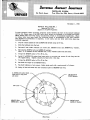
INTRODUCTION
This mqnucl contqins routine inspection, mcinten(trlce, overhcul, qrd minor
repcir procedures which ccn be cccomplished by propeller servicing fqcilities.
These instructions ctre intended to supplement the criteriq set forth in Civil Air
Regulctions Pcrt 18 qrd Civil Aeronqutics Manual 18. In no cqse cne they to
be construed or interpreted qs overriding or contrqdictory to the inqteriql in the
regulctions or mcuruql.
The use of this mcrnuqlby crty propeller servicing focility shall not, under
cgly circumstorces, be interpreted or construed as qn approval of the focility
by universal Aircrqft Industries.
NOTE
This rncuruqlhqs been cpprovedby the Federcl AvicrtionAgency.
Reviged JulY 10, 1962
- t -
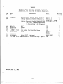
SECTION I
SPECIFICATIONS AND DESCRIPTION
A.
General Specifieations
T1rye
Number of Blades
BLade Material
Hub Material
Engine Shaft
Total Pitch
Low Pitch
High P itch
Weight
B.
Hydraulically
Operated Constant Speed
T\vo
Aluminum Alloy
Steel
Flanged Shaft 4 inch Diameter BoLt
CircLe, L/2-inch Bolts and Dowel Pins
20 Degrees
Adjustable at Piteh Control Arms
Fixed High Pitch Stop on Piston Rod
68 lbs.
Range
Installations.
Aircraf t
Eng ine
Rat ing
Propeller
As sy.
Blade
As sy .
Beech Debonair
35-33, -A33
35 -B33
Continental
r0-470-J
r0-470-K
F12A-4, -5
8400-0
84
82
F 12A-4 , - 5
8400-0
84
82
Beech Bonanza
H35
J35, K35, M35
ContinentaL
0-470-c
r0 -470-c
F12A-5
8400-0
84
83
F 12A-3
8400-2
82
81*
N35, P35
r0 -470-N
225 HP
25OO RPM
225 HP
2600 RPM
240 HP
2600 RPM
250 HP
2600 RPM
260 HP
2625 RPM
F12A-3
8400-2
82
82
Propeller
D iameter
Max. Min.
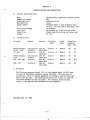
C. Governors
governor Model 1F-1 is the Garwin Model 34-825, and
The Flottorp
is used on the Beech Debonair series aircraft.
For service instructions,
refer to Garwin Handbook of Overhaul Instructions
and
Parts List No. 825. The Woodward governor 210 series is used on
the Beech Bonanza series ai.reraf t.
For service instruetions,
refer to the appropriate Woodward service manuals.
Revised July
10, L962
-2-
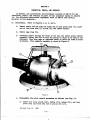
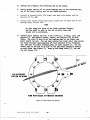
Do D6.crllrtl6
|!b. b'l$ d tb. lbalcl S12 DrsDeU.r 1g uchLnoaf fio rcli,€al .nil ltrl!.&br.tcil atcat ttDL!8, aoit fu ctlaoh.d to tbc ."dnc cslalsbaft fiangic rltb 5
Dqlta rd I ilorglgr G€ brD coolosca tbs hldaaultc lrtrt@ ad glrto
roiL
lcnrd
of tb. btib boalvr l&. IflltG sal tg stta.b€d to a brr that lLlts lt rltb
tb. lto bfribg tbouSb boXl-Joflt lt!L6 ftlcb €GtfrdJr dltd^ratc aJJ, btliltr8
A pmract
l^l tbr octrof
lysta.
luhalca,Et Lr uccal ltl tbc batrl Joil,utr to
dlld^ntc
tbs mca$lt3r fo gctoillc
lubrloatto
fc tba :l,fe of tba lrolnlJ.eo
lltc blrdor lrc tGtsfural tB tb.
anil tb b€arLlg r.ce! litc a plt d
brrlDg !aa.! !a! ibd,groal ro that
aao bc tacikcor '.;t lev raoca rlb1cb
bS
tbc
tJ lt
btr!
ty a r.ctcutlo urtr llbc r.stcctlo
a|rt
blaila
esacdlyq
Emrrrl
tha
lleuneut
bccor
[oco3lerJr to rrf:.ecc tb.$ tbry
IasvlousLy beco 'o*co cm bc trtall,cit.
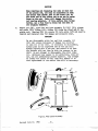
fbe alt''n{nt& alloy splDrler atre.'nl 1tleg tbe propeller lnsta].l"etio
a,nd
contrlbutes to englae coolLng. Ebe splaner tloe ls attacheil *trelJr to the rear
bullibeatlo Dralu bolee La the rear bulkJoeadlf,lange preveat accruuLatlo of
nolsture vhlch coultl cauEe ao out-of-balalce conelltlon.
ALf fucttoaS
lnrts of tbe astuEthg locbatrls ar6 lade fro Et€f&{La
slnclfleal.JJ relecrtedl to regutre !o ldbrlcetlon.
lnre r.ct€Etlo aseaib\r 1r
greaacl
rltb
requtrtng
aot
re5flenJ,ahmt
ilurtng trbc ovalbarrl BcrloiL
Irre[nckeil
AIL grcee ad oLl aealg aro strthdtc
rubbs ne dDgs qrelailng at Lqr llressrE€
to aerrre log llfco
ALI pr$r BubJ€ct to cmoeim a;!e anoatlz.al c arotected
bt stdtdl.e ptsttug.
E.
H,mlI)J€s
d ODcFtl@
Ibs lbabL El2 oorstaut alteeif prolnller
le a gbgl€-s.ttlg
unlt ust!8
bvdraulto lrlrossw€ fc tmrcslng
tbc blad6 angte (ahcregallrg nl!l), o.il thc
lattaal ceotrLfueal trfitEttug noent of tbe bladea fc ilecroeatng tbe blaile aogle
(fmreashg md).
IbB hdrdrltc
rorEce f6 olr.ratl,oo 18 otl tto tb. eogtlc ldbrlcattag syEtco
boooteil l.a lrcaarre by the gweorrc gear Xrrqr, aad tq4itteit to {rb€ lrqtcl.ler tbougb
tba lro3offe
shafl flaDSe. l c@wstt@al gny€lrDbg cydt€o (c€dtrltugal figrletgbta
balancell b5r a s1la.de slrbg operattng a ptlqt ralve ) rtca
od-Lto alll 1!@ tb€
(bcrcstDg
blrda
taceeeatrg
I
ths
a[gL
to
ualrrlatn
a lre-seJ€ct€il nPM.
Irlopcll,e,
In c.se d latlure of tb. oIL rq4{y to tbe fnolteffer, tbc blados rtLL gp to
lor pltobo lHd thls cdltloo
flfgLt !ry be ualtrtat!€if .t rcouccil tbottl.e to
c-e!lr3
oYlersP€ealtlgt
lbere
eufflclcort poler ta ara,llabJ.e to cltlib c cr|ds€
lrsvrct
at rrrlour fugEt e@trt€raatlms at f.ore fmsal
atr$|ecal'.
Revised July
10, L962
- 3 -
s
sEglroil
II
SERVICEIO0IS & 4UrruENr
TU
OnIy one speetal tool
p"opeller:
ls necessar]r for nalntenance aad overhaul of the
&lade Retentlon
Standard tools
the Fl2 propeller:
Nut Wrench, Faft No. EgtgOOO
and eqrrllrnent necessarJr for nalnbenance and overhe4l of
Propeller
Assy. Table
Plters for Internal Snap Rlng
(Waldes Truarc No. j or No. Ar, 90o tips)
Suspenslon T;4re Propeller
Revised July
10,
Balancer
Lg62
- 4 -
SffiTION III
PERIODIC NISESTIOIq AID UtsruCATION
A.
Ferlodtc
Inspectlon
Cougronent
Propeller
Eub
Propeller
Bl"acles
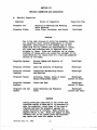
Nature of Inepection
Inspectlon
Secrrrlty of llouting
and Mouotrng
Bolts Sa,fettecl
Mlnor Nleks, $cratehes, and Cracke
Tlrne
Postfllght
Postfllght
CAINION
Due to the btgh stresses to wbLch the propelLer bl"acles
are subJectecl,, tbelr careful nat^ntenauce ls vltalIy
pa$teularly
lultor{ant,
on the leadlng etlee of eaeb
blade frm the tlp Lnboard for alproxLrnately B tnches.
ALL nt cke and gcratches must be re;ralrecl before the
atrplane ts floru.
Nlcke and seratches set qB conccDtrattsas
of etress vhlch cqn e:(eeed the strength of tbe
blade naterl.al;
the result trlll be a crack and proatnre
failure of the blade.
hopeller
Sptrner
Obrrloue hnage ancl Seeurtty
!,!ountlng
of
Fostfltgbt
Propeller
Govemor
leaks and Securlty
of ldounttng
Postfltght
hopeller
Controls
Governor
Connecttons ltbchanlcally
an<l Sa,fetted
Propeller
BLadeg
Corroelon, Cracks, lfteke or Dents
Beyond PquJ.selble T.lnr{ts
hstfllght
neareet J0 houre
Propeller
Controls
Gqvernc
Trave1 and llear
Postfllght
nearest J0 bours
hopeller
Bledes
f,ub ancl
&lade Retentton
Irack
Fostnlgbt
Secure
and Propeller
Postfllgbt
neareet 120 bours
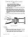
}IANNINC
Durlng poetfLtght
lnspectton tf the lO-ltf0 fuel
lnJectlon engine ts ranm and lt Le necesearSr to
norne the propellerl
stsnd clear of the area of
and novu the propeller
rotatlon
agalnat the
nomal dlrectlon
of rotatim.
Make certaln the
pagneto grltcb ls off.
Ifhtle tbs eaglne te rnrm,
resl.tlual fuel ln tbe lutake pde
and hJeetwe
nay lgnlte and eause the englne to klck.
Revised JuLy 10, L962
- 5 -
Cqtrnent
Ibture
hopeller
Blades
ffub and
Propeller
Assenbly
Govemor Asoeobly
B.
of Inslteottoa
Vlstal
IneBeetlou TLue
Overspeed qp to
3I5O rlm (f tUe propeller
exceede 3L5O rlu, replaee
lt. )
0verbauL
At tilnglne Oyerbaul brrt
not to excced l0O0 brs.
Overbaut
6
nlglne
Overharrl
Irrbrlcatlon
No orternal lubrlcatiou
of any trnrts of thls propeller ls necessa,ryo
At overhaul, af,ter cleanlng and lnspectLon of the blade bearing raees and balls,
they should be repacked wltb clean grease euch as Sinclalr AF iio. 2EP. Prior
to assembly, a1l O-Btngs, and the surfaees on whieb they ride, shoulcl be coated
wlth a lubrtcatlng
o11 to facllltate
tnstallatton,
and prevent tearlng or
sbearlng the O-Ring.
Revised July
10, L962
- 6 -
AgTId
IY
rullEnst
l{l.th proper care, the I'lodel F12 lropeller
can gtve Dary hour6 of efftclent
opelatl,on.
Inspect the bleites and hub at the recomenaleal lntervaLs,
anil pelforn
orfly tbe lslntenance
clescrtbeal ta the follortng.
paraglaphs; tBlatenance and
repalrs $blch requlre nore lnvolvetl Broceclures c <llsaseembly of the protr)eller
nust be perfornetl by a FAA certlf,lcateil
prqrelLer repalr 6tat1o[.
If an out-ofbil''nce coDalition ls euspectetl, remone the propeller ard eend lt to a FAA
propeller
certlfLcetedl
repair statl@.
Llne nalnteoance personnel ahou].d not
att€spt to balarce tbe p:lopeller
slnee balance proeealureB a,re lntrLcate
aril
requhe Epeelal toolE and equltrnent.
A.
FonrsUaa Rorat
gbould bc l'lr tbc futl tor t'lten-hl8b r1n po3ttl@ b€trGe
lba polnl"lcr
bcgl.utlg !@iatr.
I|osallJr, tb. IEolcllra rIfX !to!) Ln tibls l|ositl@
ad th. Dtst@ rlll bo tn itg stse
a,fb l|o6ttl@, fcarfng a d.!t!n
aroEt oE otl $ttbh thc ogrlldcro
A rag gbonld ba kelrt hant' to c6tcb
th. otl tbat ts SGrd aha{ng tba rorral
oD€ratl,oD. ncoove tb€ l|rqreUc
ae foLLon r
'
Lo Rov! tbc tll 4tl,Ee ilo rctrfrlf.Eg icrsrr, adl rova
tb. at€!e, taklng
car. that tbe Itropclfe bbdca arc not dogciL
lhr.k tbG ilo ad nttae
brlthcaal fc ldcttcal
lf, tb. Gfd.lrl
Grktrlg bar bcen
rc:1trrtalbtt6,
oblttcateilo
2r
Br lllm
bvr
tb stx nrqcU.cr rchfir.lg
bolta aoil msbccr at tb. afaolsbf,t
ft algt roil rr@ve tb. 1roDelJ'cr aracnblgro
lelnlry
CLcaotog, anif la4rctto
No retr)alrs are authorLzed on tbe propeller bub, and the only acceptable
nethocls of, repalrtng cuts, ntck6, cracka, ete. in bleiles ere those by whlch
the da,uagedptrtlon 1,6 removetl fr@ tbe blades to Leave a suooth well-f,alreal
eurface. ldethods vhlch atteqrt to relocate netal by cold-rlorklng to coner
or conceal the defect rathe! thalr renove the danage are not pemlsslble;
acceptable blaile repalrs are tleecribetl ln CAM18. For cleanlng, use ran:n
fresh $ater anil soap, tml66{s{ gasolLne, or keroeene, atil 6ultable blushe8
or clorbhs. Afber the blaites have beelr cleaae<l, alJ. cleaulng substa,nces
Dust be lnaetltately resoved. Soa? h alJr fotr shoulil be renoved by tboroughly
risslng rlth freeh r,ater, efber shlch 6lL ateel eurfaces shoulil be dried aurl
coated vlth. cleao englne o11. SeraperE, poyer buf,ferB, 6teel brushe6, anal ary
otber tools or eubstancee that lri].l Eclatch or othenrlse m! the eurface mugt
nott be used o bladee. Ia speclal caEes rhere a bigb pollsb la tleslred, a
gooalnetal alrcraf,t poltrb roa,ybe useil; borever, $ron c.rnfi'letlon of, tbe
pollshlng, arL traces of poltsb shoulil be lm€iltatety removd. I! Do lDstaace
sball the b].adce be pollehed t.ith a poler buffer o
C. hq|cl.Ls
To turlall
1.
lEtrUrtl@
tbr lnoltcl,fc,
ulc th. follovl'lg
D8cd|c
t
AIl6p tb tno gpfilc lflil t.a tbc polrll,c
hS trltb tb. ccr.rDdl'lg
bdlc ta tbc r4gln omohrbft tf$g.
CastlS thc br l btrd. o th.
Revised July
10, L962
-7 -
-l
81d',eof the IIC mrk
2.
Instal,I the 6 retalnt4
lnch-poundg.
3.
Seeure the bolts
b . Fosttto
alrd lnstalt
D.
on the englne fl"anger erd lnstatl
rtth
bolts
and raaberg.
[rack
Torgue tben to 6OOto ?00
safety ylre.
splmer d@e oa prqpeller
fe retalntng
8Gr€FBr
Checklng Pro1leller
the propeller.
accordLng to narks mde on renoval,
ln the Srop
L.
Hlth the propeller
2e
PLace a etatlonarJr obJect et the ttp of one of the btades and nake a
uark on the obJect wbere the eeuter of the bladc touebes lt.
J.
Rotatg tbe Bropeller
tLte bl"ade.
l+.
ln lon pltcb,
nount tt
sn a protractor
beneh re,ndrel.
l8O degrees and repeat the above openatlon rttb
lbagure thc dt stance betreen the eenterlineg
ar lorable dtffsrenc€ fs VB tnch.
of tbe tro mrke.
Tlre
If the dlstance ls greater than 1/B lnch, the propeller shou].d be sent
to a FAA certLflceted propeller repalr statlon for frsther inspectLon
and repaLr.
Checklng hopelter
Track on tbe Alrerafb
5.
E.
lbe follwtng
procedure shouJ.Ancyt be atteqrtetl rrnl s6s lt ls knwn tbet tbe
en8lae sbsft ls nst out of l,lne.
Ifhen ehecklng tbe track, the alrplane must
be ln a hangpr nlrere air currente ylll
not roc[ it.
use iue fouorlng
procedure:
I.
Plaee a stattonaalr obJect at the ttp of one of the bl,adee and, uake a
uark on the obJect rbere the cerrter of the blade touchee Lt.
2.
Rortate the propel*ler
thls blade.
3.
tGagure tbe dtetance betrrcen the eenterllnes
allombJ.e dt*fereuce ig t/8 Ucn.
I8O d,egreeg aud repet
the abwe operatlm
rtth
of the tro nrkso
the
h.
F.
If the itistance le greater than 1/S lnch, the propeller should be sent
to a F:l[A certlfleated
propeller repal.r siatton gor fgyther inepectlon
and repaLr.
I.ow PLteh AdJugtnent
Low pitch settings for the F12 propellers are measuredet the
33R blade station.
Revised July
10, L962
- 8 -
-g
Aircraf
t
Beech Debonair
35-33, -A33, -B33
B eec h Bo n a n z a H 3 5
B eeeh B o n a n z a
J35, K35, M35, N35, P35
If the pitch
the following
angle is not
procedure:
P r o p e l 1e r
A ss y .
Blade
Assy.
F12A-4, -5
8400-0
lr.70
F12A-5
8400-0
13.00
F12A-3
8400-2
13.50
correct,
refer
to Figure
Pitch
Angle
1 and use
l.
Wtth a hercagonlrtench, loosen 2 set screns (f ) in each plteh control
qru (2) (oue ln eech balj).
t'lrts v'tII requlre scne effort to back then
out agal.ngt tho sa,fety staklng.
2.
Renove cotters
3.
amd Loosen the 2 c]erTp bolts
(3) on each bLade.
AdJuet the blade pttch to tbe deslred angle.
C.AtIrION
Ilo not atteultt to adJust the propeller blade angle
nltb the pltch eontrol ltuks (l+). Although tbey
agl,ear to be ttnrnbucklesl they are not, but qre
pernanently plnned together.
Aqy attwpt
to rotate
the eleeve of thls ltnk vtLl, dauage tt so that
be necese8{o
replaceroent of tbe enttre lLnk rltl
cAr,nroil
The plteh ehqnge llnkage ln thts propeller
bas been
purltosely destgned rrlth ba"ll, Jolnta to ellnlnate
all
blndtne tn the B]rstem dmlng operatton.
1'lre llnks (t+)
ytIL alrrays be ln tengl.on, thua seektng to reualn ln a
ptane Daoelng tbrougb the plston rod. Tb,ls rrlll cause
the front croes bar, plston rdr and plston io rortate
a Boal.l anount durtng travetr between tbe srtreues of
pltch.
Hovever, Lt tbe natural forces are reversed
(1.e. ptteh ls lncreaged nsnual.ly by tvletlng
the
blade, or plteb ls decreased uauually by pushlng beek
on tbe front croEs bar), the llnke ntlL tben be ln
coqpreselm, and r11I eeek to altgn theoeelvee
peqpendlcuLar to a plane IneslDg through tbe pteton
rod. nrlg aetlon rfII
cause rotatl.on of tbe front
bar untlL tbe eods of tbe ltnk Jan agglnst tbe bar
(23) m agalnsb tbe ptteb arm (a)r whl.cb places an
undue strela on tbe bell Jolnta tcndtng to pry tb€B
apartr
If, no resLetance, stber tban norul
frlctloo
of the oyeta ls €ncouutered, the Jolato rILL uort be
harned. Eonever, t^tr any ca8e, tt ls strog\r
reemeorded, tbat rhen adJustrng 61 shanging tbe pltch,
inerease tbe pltcb by pulllng oo thc front cross bar
Revised July 10, 1962
- 9 -
at tho eenter, a.d decreege the ptteb by trrlettng
both bladeso tbt s not qn].y rrtt protect tbe bqrt
Jolnts agalnet da-ager but rrlll also ellmlnate errors
ln eettt-ng tbc plteb.
lr.
ttgbten
tbe eJaq borte (3) to proper torgueo (see Ftgo 6).
CAT'TIOI{
It le extreoe\y l4rortant to apply the correct torgue
to tbege nutao lbe cJ.aryrng ectlon of tbeee bolts
plue thc blttng of tbe set screr tnto tbe retatrer
nuet reelst the cedrtf tlgal, trrls:t{ ng nment of tbe
blade mdcr rrtbratony condtttoos r rf etther or borth
blades sltp frm tbelr eet poeltl.on tbe propeller
trttt becme ertreoely roqb frm aerocttrrnanl.cexeitetLonc A fcced landrng Day reeult.
G.
5.
Re-eheek the pltcb
6.
Install cotters.
ff cotter hole does not ltne Epr alrays adrnance nut
to next slot, ag long as torque does not exceed 1l+Oin. lbf--
7.
Tlgbten tbe eet serffs (r).
8.
Stake the set screvs rrlth a center punch.
angle.
If
tncorreet
repeat steps 2, 3t and l+.
Governor l,lrlntenance
G o v e rn o r ma i n te n a n c e th a t can be performed by operati ng
personnel
is
limited
by the availability
of special facilities
required for extensive
r eP a i rs .
Go v e rn o r re p a i r
and overhaul
shoul d be aecompl i shed onl y by
facilities
having adequate servicing
and test equipment, and either
G a rw i n M a n u a l N o . 8 2 5 o r the appropri ate
W oodw ard servi ee publ i cati on s.
Stnce Sovernor aetlon ls d,lrectly related to the propeller plteh cbn"g{ng
neehanto,
there are very ferr governor troubles that ean be lsoLated rtth
the gwernor tnstalled
and operatrng.
Fatlure of tbe prqleller
to cbange
pttcb correctly ntgbt be caused el.ther by the gpvlmor or the propelJ.er.
Sccept for locatlng obvlous troubles,
lt ts beet to replace tbe goyernc
rltb one botm to be tn Sood condttlon when trouble occurs ln the propelter
!ttcb-eh+n81n8 eysteo. If tbe troubLe dleappears, the governor ras at
fault;
tf the trouble perslsts, tbe prolnller
m,y be at farrlt.
The gwernor ls notnted oa the engino pad rlth
nute.
Rclloval ls accqrl.tsbed as foLLor{B 3
l.
Dlgeonneet the eontrol
2.
Reuove the forrr mountt'g
3.
Inetall
4.
Cover the englne pad rrfth a drqr
four strrcls and self-locktng
bracket at the governor control
nnte and pull
the governor frm
lever.
the etudE.
a sblpptng cover on tbe governor bage to prortect tt.
Revised July 10, 1962
-t0-
basc or aecesaorT/ pad correr.
rnstarlatton
r.
of the governor ls aecm;rrished
use a erean dry crotb and rlpe
as follows:
the engl.ne pad crean.
CATIIION
llhen lnstalllng
the goveraor nske certeln the nare
governor
spllnee oa the
drlve mesh wlth the feuale
spllnes oa the englne rtrlve before placlug tbe
gsvernor on tbe nountrng parl and tlghtenlng
the nuts.
2.
Place the nountlng gesket over tbe engl.ne pad studs $ith the ralsedt
surface of tbe gasket Bcreen factng a$ay frm the englne.
Do not u6e
sealtng cw;rorrnds of antrr klnd.
Place tbe gwernor J.n Bos!.tiour on the
nountlng sttds and rotate the proSre1J.er sufflclently
to meeh the
go\rernor and englne drl.ve spl,lnes.
I,lben tbe spLtnes are meshed the
governor rlLL easiry fl.t lnto place on the englne pad.
CATNICI[
Do not force the goverrlor onto the englne pad. To
do so rrlll force apart the beveJ.ed.gears Lu the
engine.
four platn rnash,ers and, gelf,-locklng nuts on the studs and
tlgbteP evelSrr Recmendecl torque ts 20 foot-pound,s (Al+Olnchpotneds).
3 . InstaII
l+. Attach the eontrol rod to the governor control lever, being 6ure that
the Lever can be operated agetnst bstb btgh and lon qpeed stof,s tbrough
tbe lrnkqge frm the coclqrtt propeller
control.
Check for excesslve
bLnd{ng or Lost nortton tn the llnkege.
Revised July 10, 1962
-il-
-- --1
sEgtrol{ v
u{sPwllff,
nEPAIn, AIID OVERHAUL
In generdr aII lnstrrctlorc
and procedrnes outltned tn C,AM18 for aIL
lnspectLon, reprair, and sverhaul of prts
of thls propeller
Ehoqld be adbered
tor
the f,ol.IorLng lnstructtons
aqpleuent tboee ln CAldtB rrfth detalls
pecultar to thls propeller.
A.
Dlsasseub\r.
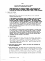
Refer to Flgrrree l1 Z, 3t aud l+.
1.
Reuove corbter and nut frm tbe blade end of eaeb ptteh Lrnk (l+)r s}lde
end of unk frm stud (5) in am (z)t and reufire rasber.
2.
Renove snsp rt^ng (Z).
3.
Carefully reurove througb the front of the hub, the entlre pltch control
assemb\r, taklng care not to ti.lt tbe Btston to cauae ft to blnd Ln tbe
cyllnder.
AIso bsve ragg or contalner han(y to eatch oll fro
in front
of pletono
fbls cqrlete
ass€nblV ls shonu tn Ftgrr e 2.
f+
;et
1;,.ri+iS,]
r
';-'ifi"litt
F i g u r eI .
l+. Dlsassenble the pltch eorsrol neebanls as follorrc (see Flg. Z)z
8o Renovenut (+)r plston (12), o-Rtne (r3)r o-Rlns (rh), anclhlgh
plteh stqp (15) frm rea,r end of plstoa rod (fZ).
Revised July 10, L9G2
-12-
CAI'IION
b.
llhoo r€usrlrg anil replacfng the nuts at eacb end
of the Bletm rod, use only an ailJustable or^qP€n
cnal rnencU rrltJl dootU Jans on tbe fiIata (22) at
tb€ fioat enil of, the pletm rod Eo as nort to ralse
burrs oa the rodo Stttzs YILL ilrnpgB tbs ptstm
If tb.lg stdace tloeg becoe
roil bartng uterialo
btmedl uae a flre fLLe to dlrees ths rod down to
lts onlgnJoal dJ,metero
Removenut (2tl), pitch bar and link essenbly (h) (23) (31)r plston
rocl gul.cte(18), O-Rtue (f9), O-Rf^ng(20) from the front end of the
ptston rod. Blarhg (2f) f; a press fit into gulite (fe) and.need.be
renoved, ancl replaced, on-ly for danage and excessive w€a,ro
CATNIO$
Do not dlsasseable pitch bar and link assenbly (\)
(23) (:r) unless looseness or darnagehas occurred
to llnk (\ ) or bar (aS). If necessary to d.isasserible,
always push on the ungrooved end of the pln (3f).
Always replace witb a nev PLnr and lnsert tt so that
the grooves w111 not line ry wttb the grooves in bar
(23). Do not attenrpt to dlsassemble tbe pltch links
(h). Although tbey appear to be turnbuekles, they are
Any attenpt
not, but are perrnnently plnned together.
to rotate the sleeve of tbls llnk will d.amngelt so
that replacenent of the entire llnk vill be necessary.
!
F i g ure 2. P i tch C ontrol A ssembl Y
Revised JulY 10, L962
-13-
t
l
(25r,
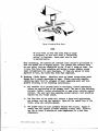
5.
Reusve hub ptlot rtng
bub (See Flgure 3 ).
6.
Reuove 2 Berero, naebersp retentLon nut locks (8).
O-RLng e6),
and O-Rtng (?fT) frm
rear of
7 . Reuove 5 loLte and uasbers (28) frm
flanse
tbe perlpbery of engf.ne nounttng
m tbe hub, and reuove sptnner rear bulkbead 8651ro (29).
CAIJTION
Ifblle renorring and. replaclng this bulkbead when
lt Ls not necessary to remove the propelLer blades,
take catre not to rotate the blacles or ln any way
Slnce the
cllsturb tbe retentlon nut settlngs.
retentJ.on nut locks have been removed,r the nuts
are free to rotate.
8 . Usrng rrencb, EB f9OOO, reuoye borth blad€ agEeublles.
PuIt tben
etrelgbt out so aB not to damge th6 tbreects sn the retentlon nut (EO)
and on the lnslde sf the bubo A rag tted aroud tbe bladc shank beiveen
the retention nut and the pltcb coutrol am (2) rfU hoIA tbe ntrt ln
pl'ace to prevenrt the loose beartng baU.B fro
falllng
out of tbe rac€B r
9.
BLade dlsas'seubJ;y
8o
Fi gure 3.
l{lth a hecagon mench, Iooeen 2 eet screvg (1) ln each pttcb control
am (2) (one ln eqch [a]f).
ThLg r11l reguire sme effor+ to baek
tho out egalnst the eafety etaking.
Revised July
10, L962
-tf-
b.
Reoove esttersp nute, Eobersr
and bolts
(3)r and a,rn (2).
CATNION
tlhen lt ls neeessar5r to reuove tbo balance
ssreru, plateee and retghta (I0), ca,refullJ nste
tbelr exact locatLon and ldentlf!
tben by blade.
yll-[ great\y
Replaceoourt ae tbey r€re ortglnaUg
balanctng the prqreller.
sfapltfy
ntrt (30) and renEve the 31 balte
Co
Ltft the blade reteotton
thrugt bearrng rac€o
d,.
Shake tbe blade retentlon ntrt qp and down to drotrr the orrtboard
thrust bearrng race frm vlthtn tbe blade retentLon nrrt. If tbe
outboard raee does not falJr rrap tape around the blade sbnqk and
Itft
the reteotlon nut abcyvethe steel. retalner.
trold the nut ln
thlg poeltlonl
sllp a flat ctrnred blunt encl tool betreen tbe bl-ade
and reteattou nut and tap ttgbtlyl
rotatlng the nut rblle tapplng
(flgure lr).
€o
I{ltb the race free fro
tbe reteotlm
fro
the
nut renove the blade O-Rl"ngr
F i g ure 4. R emovi ngB l ode R oce
B. Inflectlm
l.
Slades
In addltLon to the nethodg dtseueeed tn CAI{ 18, ansther eatlsfaetory
nethoal fc detectlng crackg ln bladeg le ae fol.lone:
8r
Revlsed July
Clean the blede careftrlly
rlth carbo tetraeh.lortde
anil dry the
bLade tborougblyr ustrg a clean atr blast 1f neceooaffo
10, 1962
-15-
2.
b.
Prepale a solrrtton of 54 son-toxtee non-corroslve
fluorescent gua"lity, and 5Of keroe€D€r
cr
Coqtletel.y t@erse the blade ln the eolrrtlon, includ,rng the blade
retalntng nut and allor lt to renaln for a nlnlnru of ih1r-ty ntnr*es.
After thig Pertdr
reuove the bl"ade fro
the batb and all,orr the
ere€88 f,luld to dratn.
Spray tbe blade rtth carbon tetracblorl.de
to eqrleteJ.lr reuove the reoalning go1utlon.
Allor the blade to
8tand, for flfteelr mlnutes go that the golutton yllt bleed out of
any eraeks lneoGDto
dr
Caref,rrlly_tnsgreet thc entlrs blad,e under I D€,rr!-trltravlolet
ltgffi
source. Tbe l4qnctlm
nUst be conducted tn a darkened boo'th or
rlo@o So,lutlon blee<llng fro
a gudaee erack rrtlt shm qr under
the ltgbt as a brigbt f,lusreeceut llneo
Obh€r Alrulnrn
Altoy
oll
wblcb has
h,lrts
Tbe fol.lwtng
lletts are struatrcal
lrarAs of tbe ptteh courtrol eyeteu
and ehould be lnspected for fattgue crackg W penetrant tnspectiong
or auodlze:
8o Pl'tch control
b.
Inspect adJacent te n'lt talped ho1es.
Ptstoa rod (f?).
Inspect each end at tbe ebotrlder fll.letr
adJaced to tbe tbreads.
Go Pltch
3.
arn (e).
lhenstlc
coartrol bar (43 ).
Inqrect
adJacent to all
and
bqleg.
Iaqnctlm
Carefutl'y tnslnct the hrrbl pltcb ltnka, blade races, retention nut,
and all gteel boltg and nute by ugnetlc
(preferably tbl
lnslnctlon
fltroregeent tvpe) ln accondnnel rrr{n the besl recq'";ded
practteeso
tlhen ehecklng the blatte raceee place a cqpl,er bralded cabll bstreen
tbe raceg and tbe blade.
fhen plac{ng tha bar betneen tbe electrode
platese fashlotr tbe cable betreen plate and bar thua tnductng ngneblc
eonfaet.
l,lrgnettze tbe reeos t.tl flne or nore equagJ qnced posittong
to lnsure cqfleto
con€rag€o No bsutat!,on !e neceesary betgeen cable
and racsg.
De.nagotlze
all lnrto Brlon to returnlng t6 eerrlee.
h.
Vl.erral Inqnetlon
Carefully lnspect a1l parte for wearr galllngr netal plckup, eracks,
nicks, burrse and dber danage. &canlne all O-Rlngs for darnage,
defornatlon and deterLoratlon.
Cbeck blade raees for chipptng at
break potnte.
Tbis eauses a ttbrLnelltng actionil to the bearlngs.
Rsces shorlng chlpplng effect at break potnts wlII be replaced.
Cbeek alL threads for rougb edgesl lrregularltles,
metal plekr4r, and
galllng.
Thorougtrly exanlne all plated and palntecl iarts for danage
exposlng bare metal.
It ehould be noted at thts polnt tbat the blacte
ls anodlzed, glvlng tt a dull gray ftnlsh.
PLated parts rlth exposed
base metal must be strlppecl and repJated.
Fatnted parts may be
touehed upr ustng approved methode.
Revised July
10, L962
-16-
rY
trolB
ll! deel lnrte tbt brrt b6c r|r-crd.|l
trll.trrlil.
lilatGd lrst bc cdrC,ttl-.rt
&cD.ct DvLlg l!r$s fc frcsd,cr d roruct.
r! th. bbd. rctab.r
fs tt€bto.r.o
hLlc
rail f;rccdc fra! Ioooc !|ar*lcl!
clarllEc.r
Cb.cts !br.!k fttt tucb
Lutcmrl lanragcr fc
otr lsta,l 6 otbs tubgtascr.
G. 8e1ntr .-il Oyubaul
lo
Eub }|lntr
nc4rulr
xlsG geIIlDS aod ecclng otr tb. lolEtLDS flroge nlr be rcr!fit(f
Iroltohbg lrltb eo€ry lragcr.
Iy
If tbe threails b tbo loult{rfg flanga erc d$BgGal, reo out .nrf fugtrll
a bdli-col.L
lil!@. 6cG|.Ig adl scratches to the alor,eJ.?ltls lr tbc
lorat'l ig fl.engc ray bc rryetl
vttb eoor? IBpca. lilde rcrlou8 alauges
to tb€ ilqt€l' pl,ns lrl'll requlra rcglaceo:ut.
Corro6loo sostLDs ilctrrlolrg
l'n thc rear lrc-tt@ of tb€ cylld€r
du. to gasGs ficB tbe olglnco Xhl,r
cqrlrollm ad/or nL[6 sc6lDg ay b3 r@sreal by ftoltahlrg slth cf,ocus
cloth.
Do uot use e!€ry IE!,ca aDil a$'r r3 r€love a DtnLrr! uourt of
lctal.
SctaB tbe bub tf tbrccdc tn tbe hub fe tbe blrd€ !,Etot16
Dut
are daoageil beyEal rsl|airo
"
2.
Eub ltaJof nepalr
The cyllailcr nay be nachtle bonealto r€oov€ rougbDe"" * ss96'lng u61tt8
a very flne stoue. AltbouAb tbo lrl3t@ bore ny bc bocil to a Err.n|[
I.D. of 2.881 bches, f,or use rlth a sta,Dalaril alzeil ptst@, oDlry the
nl[t I arou[t of, Bt€rlel
nccessa,nJrto cleen t4r aDJrBcclag should be
tcoovd.
Cele nust be cxenclse<l to Dlntallr stralgbt cylbd€r r,8LI!
tbrougbout the area traveleil bJr th€ p16tm.
3.
SplDna nslnlr
I!6pect tb€ splnDer f,or cracke, tearE aJodotber dFE ge. &eLL cracks
eay be 6tol,-dr11led.
I{o patches of aloublerB are recc@€lrded bscause of
the crltlcaL beJ.arce [email protected] to be nabtetned.
Should tt bccooe
leceasar]r l.lt aa euergency to add a patcb on a tloubJ.er, bc aure to adil
@e of egual $etgbt to tbe opDoslte Bl.ale. Foll.sh olrt nlDor d,cks aDal
scratcbos rlth eoer5rpeper.
l+. Bletle nllor anal eJor ne?alr.
CAM18 are pennlsslble.
Repaire oD,ly vtthin
the lLnltetloDs
of
l. BLadeBea,rlag Bace6. AlL blacles bave tbrust bearlng race6 wlth groove6
grounil IBO degrees apart lu the eft s1<Ie. Thls groove asslsts la breaklog
tbe race for replec€ueat antl vas tleslgned for thst pufpose. Races caDnot
be repairedi tbey rs6t be retrrlacetlnhen tbey beeonebriuelled or cblppetl.
If raceE ln stock are riet broken, devi.se a tool to break tbe races (see
Ftgtue 5). Set race 1n prcrar and place tool above the !ace. Brlnglng
Ilres6 tntg actlon, exert atr even*lfeg-gure over the grooveg cut ln race8.
Revised July
10, 1962
-17 -
Fi gure 5. B reoki ng B l ode R oces
NCTg
Be sure break Ls even and clean rrtth no chtps
ln evldence, ae thLs lrllt ceuse a nBnlnell.lng
actlonn to bearlngs.
Races must also be kept
tn natcbed. 1nlrs.
I{hen tnstaillngr
tbe tnboarcl and outboard races should be posttloned so
tbat the breaks sre 90 degrees apart.
The lnboard and outboard raceg
are not all.kee they are ldenttfled
by tbe -2 anil + strrE on tben.
The
-h race ftte tuto btade retentLon nut bavlng a Larger cbader arorrnd
lnner ctrctderence
for sel clearance.
If tbey are pt-aced l.n blade
olpoette to thls, the blade rtLL btnd rhen tigbtened.
- &lade Regalrr Caref,ulty toueh rp bladeE bavlng nl.nor palnt
6. hiutrt'g
danage dlue to relnl.r operatlms ot r€rtrro BLadee requlrLng cq,lete
patnt and then
retrnlntlng shell fl.rst be etrtpped of thelr rmtnlng
trntnted aceordlng to tbe fox.lorlng lnstructLms:
8o
ALt eurfaces to be palnted EhaLL be thoroughly cleaned Lmedlately
before the appllcatloa
Use one of tbe foll,orlng
of the prf.mry coat.
solvents: benzol, earbon tetracblorlde
or s@e other sultable orgenlc
golvent.
Use ss,mecare rhen applytng secoud topeoat, tbat preeedlng
topcoat bas not becme soll,ed.
b.
Tbe flat face of the blade rlLI recetve a tbree-coat alpllcatlon;
one prl.uary coat aucl tvo topcoeter
ltrek-off the camber faee of tbe
bJ-adep ustng any suttable rnethod.
Co
the Brlner shBLl be zlnc chrmate thtnneil rltb to1uol.
Atr4,ly ft
even\y over the eurface of blade avol.dtng a hew coet'
ALLw to
dry for at Least 30 ntnutes at tro@ teqrerature
ln a clust free
atuospbere.
Revised July
10, L962
-18-
af. AIEIV tbc f,l.rgt tstr)cct 60 tbat lt eoners tbc !,!Lu!.rJr coat caq,I€itely.
Itbe tq,c€t
sbal]. be caroufl.age fl.et bbck J.acqucr tbt-@€il rltb
ccllulole altrate tbtaer.
They sball ba tfugrrgrrr y d.xed befce
8IEilVr!8.
e.
Al].or tbe f,trgt topcoat to dry thdougbly (at J.eaet 15 nlauteg ) adt
then a1[ily the secod topeoet Xn a dlnl.J.ar la@ero Allon tb€ fllal
topcoet to atry fG at ].eaet tro houre et a roul
loo teq)€ratlEe.
the blad€. sbal]' not bc coslilered t€aily fon s€firtcc r8ttt tb€V bsyt
alrteil for a perloil of 1l8 norce.
f.
AIEIV o6 coat d zlnc cb!@tG prLoor anil tro coets of carouf,l.age
flat yeJ.ltr lacguer to botb sldes of tb out€r forur bcbee d tbi
bladr. Aleo aptrr\y e Btltt e otr yeJJ.orrlacquer at tbs 33 la. r.tf€fdce
gtatlon oo the flat f,ace d tbc bJadc. Ibir sbrUre sball be
V8 trr.
vlde by 2 tE. tn leugth starbhg X /8 tncb€s fro tbr feadflg'cd83
of th6 blrd€.
S.
Instql r tbe b€artlg baIL td@attoD
alecal o the flat fsce elde otr
the bl.ealc arnnke I t/r taelee fr@ the EteeL rdaller o Af,tcr lt hag
drled, agp\r clear Jacquer ovelr lts Eudace.
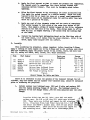
D. Asg€obily
tfhe6 a8redl,lag tbe t)roPeller, almye re!€[ber s before llsertr ng O-R!.!g6e
atElJ a coetlrg of cl€aa engfue ou to tbe o-nfugs anil to elL grrf,aces outo rhtch
!t"y gI-" a8c€[bleilt ag{p tbe proper torque to all scrers, bolts, anil ants (eee
flg. 6ri safety all bolte, auts, sclevs, etc. rhere lecesgary.
Iteu
(3)
(5)
(11)
(2 8)
(2 8)
Parb Nunber
Paft
Parts per
Propeller
4
2
2
2
6
6
6
AN31o-s
AN31o-5
AI.r4H7A
Pltch Control Arm Clamp Nut
Pitch Control Arm Stud Nut
Retention Nut Lock Serew
A r { 3 6 4 - 1 0 1 8 c Piston Rod Nut
Alil3HTA
Spinner Rear Bulkhead Serew
AI.I4H7A
Spinner Rear Bulkhead Screw
ANSH1OA
Hub Flange Attaching Bolts
Figure6.
Hrench Torgue for Boltg 8nd Nuts
Torgue
(tn. tbs. )
L20
100
70
450
30
70
600
to
to
to
to
to
to
to
140
L20
90
500
40
90
700
Stnce lt ts necessarlr to pass the spiucll.e of the balancer throtrgh the hub
cyllnder,
only the bl"ades and the splnner rear bulkbead assJro shouLd be tnstall,ecl
prlor to balsnctng the propelJer.
1.
rustalr splnner rear bulkbead &Fsf,o (2g) antt 6 bolte and naebers (AS)
onto the engtne nountl,ng fl-ange of tbe bub. Tlre brrLtchead ehould be
parallel, to the hub fLange rtthln
,040 TIR wben ueasurecl near the outer
f,lange.
CAUTION
Propeller FL2A-4 has hub 2L2 (SA*I I thru 206) and FS200
sp inner as sy. (No S4{ or S,zt{ thru 2I3) which uses bulkhead
248. These parts are drilled
and tapped for Al.l3 attaehing.-:
bo1ts.
Propellers F12A-3 and F12A-5 have hub 2L2-L (S,/l{ z}t"
and after)
and FS200-1 spinner assy. (S7t.I 2L4 and after) whi
uses bulkhead 248-1. These parts are drilled
and tapped for
AN4 attaching bolts.
Take care not to interchange parts.
Revised July
lO,
1962
-19-
i
2,
Instalr
3.
Assure prqper seattng of the outer bearlng raee ln the retentlon
and, of tbe lnner beartng race on the blade retatner.
4.
Insta1l Jt bearing balls
Sinelair AF lilo. zEP.
).
Install both, blades being espeeially
bearlng balls to fall out.
TISIE
tbe O-RlDg Ln the retelrtlm
7/L6 dian.,
atrt m tbe b]nde.
nut,
and pack $:ith grease sueh as
careful
not to alLor any of tbe
At thts stage tbe faees of the blatle retaLner flanges,
and tbe shelf or geat ln tbe bub on whLch they reet
ehould not be Lubrtcatedo
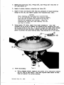
6.
InstaIL ptlcb coutroL am (2)r 2 set serewe (1)r 2 bolts, nute, aad,
uasbers (3), and baLance acr€yep plates, aotl wel.gbts (fO; on eaeh
bLade. Tbe stud (5) nust be at the leadtng edge of the bJ.ede, and
potat towarcl the hub. Tbe am uust enelose the rldge rhLch runs around
the blade retalner
approxL@te\y 3/h lncb outboard of the reteutl,on
nutr aod mugt be pushed, outboaril unttl lt rests agatnst lt.
Set the
center Ltue of the a.m at t6 ].,lZo
blsde
to
the
reference
etatLon
334
-Surrg
on each blade (eeq FLgrre ?).
up the clary boXts (3), but nort
tbe eet scrffB (f).
3 3 RR T T T R T ] I C T
srAIr0lt 01{BlAlrt
YIil
WITHBlADI IIP ]ITARTST
OBSTRYTR
Figure 7. Pitch Control Arm Setting
Revi sed July
L0 ,L962
-20-
--l
,
!,:i..
'.
.,
T.
Ealance the prqreller
B.
Removeboth blailes, "nA tfUerally apply greaee such as Slnclalr AF No.
2EP to the face of tbe blade retainer flanges; ancl to the shelves or
seats in tbe bub on whlch tbey rest.
9,
Re-LnstaLL blades. tLghten the retentLon nut unttl, alt play
thpn rotattm)
OtsaUrears frm the ttp.
Ioosen the nut I to
notehes mtll
a snall anount of play can be felt betreen the
Over-tt ghtentng rtll
retaLner.
dnrnngethe bLade bearLng and
operatlon of the propdler.
as outllned
tn fnragraph, Eo
(other
L Llz
nub ancl
tqralr
10.
rnetsll
LL.
Into the rear of the hub, lnsert
12.
Stand tbe hub rith the englne rnountlng flange d.ornnon a snooth surface
(25) frm ell14rlng out.
that vtll prevent the hub pllot
13.
Assenble the plston rod (I?)r btgh pttch stop (I5)r plston
o-Rtnge (rS) ancl (Ih), and nut (Il).
1ll.
Insert thts assJto tbrough tbe front of the cyl,tnder, taklng care to
prevent shearlng tbe O-Ringsr alxd to prevent the pleton fron btndfug.
15.
Porr t tlZ
2 6crews, washers, retentim
(27).
nut locks (B),
hub plJ.ot (25\ and O-Rings (26ll antt
to J oz. of clean engl.ne oll
(12)r
on top of the plston.
NSIE
The purpose of tLts oLL ls to prevent
eqrroslon of the exposed surrface of
the cyllnder between sverhauJ' perJ.ods.
16.
losert pLston roct guJ.cte(IB),
rlns (?).
O-Rlngs (fg) ancl (20)r ancl Ensp
Nqm
Tbls assf,r nay not stay ln lte posltlon
untll lnstallatlon
of the snap rtng because
the alr trapped between lt and tbe plston
wlll be ccqpressed, and rtLI tend to force
the guJ.de &ss;rr out of the bub. Eowever,
thls coqpressed aLr rrlll be useful Later
to belp keep tbe plston to the rear of
the cy1lder vhtle settlrrg the Lor pitch.
1?.
InstaLL pttch bar ancl Llnk a6Blo (t+) (23) (Sf) and nut (24).
NOTE
It lrtll be necessary to use a llttle
effort
to pt&L the plston rod out of the cyltnder
agalnst tbe cqrreesed aLr far enougb to
uae a euooth rreneh on tbe ft"ats on the
front end.
Revised July
10, L962
-2r-
Ip.
Inspeet for and reuove burrs on plston
L9.
Place a AN960-6L6 ragher ou stud (l) ln am (2) ana gltde end of Ltnk (t+)
onto stucl on tqp of naeherl tnstall
nut.
Repeat fqr other blade.
rod at tbe flats.
2O. Ioosen the cla$r.bolts
(f) in each pltch &E!u Set tbe blade lor pttch
aogl s of 1I.?"
at the 33R bfade referenee statLon.
TLghten the ctaql
bo1ts. Recbeck plteh and reset lf aeceesarlr
Torgue tbe nutE and
{nstall co,ttere o
CAI'IIOI
lftrea aitJustr ng tbe blaile I,ttch, o! nten ebanglng
Ifltch Duuar ry, obecrve the cautl66s Doted 1n
SectloD fV f3 of tbl.s naoual.
21.
E.
[tghtelr the eet ecretre (1) and gtake yltb a centetr 3tech.
Balance
_ FoJ.lwtug a4r aS6rrecl.able bJade relnlr, proSeller overbaul, or DaJor IErt
lepLac€netrt, tbc properler assy. nlrat be beiaoeeil. fbe ausleaeioa tgre berancer
ls rocdn''ienflealbecauee d the ttlrest tnitlcattia
of tbe attreatim ltr r.blch tbe
prolnLler ts out of balaoce, lro aleLlcatel.y sauu6tett bgrance t|Blrs are neceaaar:ir,
'ard because
of lts eeee of tEteq)rebattoa.
Yeltlea1 bala,ace otr each bladc, anil ftnel balance otr tbe propeller aesy. ts
aceqillebed btr attacr'r "g lead eegnents togp€il by eteer pJatee r*h cap scrers to
the outboeral f,acc of tbe pltcb corrtrol am (2). The leail s€gnents cao-be crlt anil
!!!ry€d to a4r slze a8 1@g ae at leaEt oD€ f,'rl, ecr* hole renalas la eacb segne[t.
The reafl Begn€lrts sboulil eltlalrs be tolgreil by a rtee]. pJ.ate. Do Dot alter tbe
eteel platea la ary tray.
1.
For the primary balance operation, set each blade engle at the
value sPecif ied in Seetion M,
and tighten each blade retai-ning nut sufficiently
to prevent bLade angle ehange during the
balAncing operation.
2.
Check the track of eacb blade a6 prescrlbed, !.n Seetlon IV D.
3.
Mount the propeller
ln tbe bal.ancer uslng the proper aclapter coDssr
l+. Add or renove lead as lntllcated
obtalned.
A
bala,nce ln all
d,lreetLons ls
5.
Removethe propeller from the balancer, and for the secondary
baLance operation, reset the blade angle 90o above low pitch
position.
6.
Irioud tbe propel.l,er ln the balaaeern
'(.
Because longltudtnaL balance ras obtalned durtng tbe prinary operatl.on,
any unbalanee that occurs ln the secondary posltton shouLd be lo elthei
If lougttudlnal
gitte on$.
unbalance ls Lndicated, reeheck the prtmary
be,Iance, tbe accuracy of the balancer, or botb.
Revised July
J
untll
f0,
L96Z
-22-
8.
to correct eldeuays rrnbalance tn tbe secondary posltlon ln a nqnner
tbat trfll uot affect tbe prlmary balance, add an qqual anount of lead
rn ! pt*ces gn thq sane srftl of the bgb 3. gg eacu@
FgtueffiFre
onffi'
r eTediiFe6-r-fscre$s rtthout
ffir?oFcm-n
any lead or plates may be used. It wotrLd also be pemisetble to use
eeveral A$95O-415 rnashers on eaeb Bcrew (tUe sarne quantlty on eaeb).
9.
Re-check tbe prfna4y balance.
If lt lncll.catea a conslderable eha.rrS€r
eecondary balancing rnas tncorreetly
accqrll.ebed.
If only a eLlgbt
change bae oceured, correct lt.
It rtll
then not be necessarJr to recheck secondary balancer
BIII]ICTRCAI1T
-F
DISCIlI DICAITS
HITYYoil IHrs SIDT
IO IT IHT
IHISDISIA]ICT
s^tt 01ttoIH B1ADIS
\
\
C . G I. D D T DW T
IO C O R T T C
UTi l B I I A ] I C T
TOUAlDISIA]ICI
C . G . I D D TW
DT .
U]IIAIATCI
IO CORRTCT
Figure 8. SecondoryBolonce Correction
Revi sed JuIy IO ,I)62
-23-
For those who bave eonventlonal balanetng arbors, adapter cones, and,
parallel knlfe edges, the procedure ls tdentlcal to th,e preceedtng instructtous.
However, lnstead of unbalance betng lndl,cated by a dlsc lndleator,
tt ls
lndlcated by a tendency of the propeller to rotate toward. the bealy sLdee It
should be noted that tbe knlfe ed,ges, arbors, and adapters must be flee from
all forelgrl matterr and must be snooth and true.
The ways sboulcl be cbecked
prLor to balancl,ng the proSreller.
for parallellsn
Revlsed July
10, L962
-zt-
SECTIONVI
f
PARTSLISTS
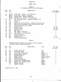
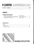
TABLE A
F12 Manufactured Parts and Sub-assys.
Item
No.
32
32
Part
No.
Nomenclature
24
17
2L
19
18
3
8400-0
8400-2
FS2OO
FS200-1
106
TL2
113
128
L29
136
s0
48
1s6
Ls7
51
24
11
11
19
13
48
7
158
L7T
2r2
2r2-r
231
237
238
24L
No. Req.
Per Propeller
Blade Assy. (F12A-4, -5 Propellers)
B1ade Assy. (Fl2A-3 propeller)
Spinner Assy. (F12A-4 Propeller)
Spinner Assy. (F12A-3, -5 Propellers)
Hub Pilot (Obsolete.
Repl.aee with part L7l)
Piston Rod
Piston
High Piteh Stop (Obsolete. RepLacewith part 231)
High Pitch Stop Washer (Used only with part 128)
Pitch Control Bar & Link Assy.
Balance Plate
Balance Plate
Balance Weight
Ilub PiLot
Hub (F12A-4 Propeller)
Hub (F12A-3, -5 Propellers)
High Pitch Stop
Retention Nut Loek
BaLance Plate
Piston Rod Guide Assy.
as
as
as
as
2
2
I
1
1
1
1
1
1
1
req.
req.
req.
1
1
1
1
2
req.
1
TABLE B
Manufactured Parts whieh Are rneluded in F12 sub-Assys. ,
But Which May Be Ordered Separately.
Item
No.
56
54
42
28
30
1
31
9
16
16
Part
No.
131
133
135
191
194
2L7
220
239
248
248-1
277
277
Revised July
Nomenclature
Pitch Control Bar
Pitch Link Assy.
Pitch Control Arm Assy.
Bearing Races (Pair)
Bearing Plaeard
Sp inner Dome
Blade Placard
Piston Rod Bearing
Spinner Af t . Bulkhead As sy.
Spinner Aft. Bulkhead Assy.
Spinner Placard
Spinner Placard
10, 1962
-25-
A ss y .
136
136
8 4 0 0 - 0 , -2
8 4 0 0 - 0 , -2
8400-0, -2
F S 2 0 0 & FS200-1
8 4 0 0 - 0 , -2
24t
FS2OO
FS200-1
FS2OO
FS200-1
No. Req.
Per As sy.
1
2
1
1
1
1
1
1
1
1
1
1
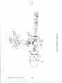
{
s-o
:€
R-g
N-C
:-e
3-l
3-g
I
U
$
=-/i/
$1*,
\ \ \
\ta
qA
c
ll|
=
.9
lll
Y
o
IJ
tr
o
T'
o
r.
o
o=t
?-r
a t
a
.t'o
o
o
x
ut
a
CA
o
3
ctl
E
Revised July
10, l-962
-26-
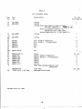
TABLE C
FI2 Purehased Parts
Item
No.
20
10
22
Part
No.
Nomenclature
AN123867
AN123874
O-Ring
O-Ring
O-Ring (Precision
No. Req
Per Propeller
1
1
Rubber Products CofBo
87 (AMS72
333-81
74)>
-
af
!,- Jb
f4{T0
t
(Plastic & Rubber Produets Co.
PRP568-333-2s97 (auS 7274))
(Parker Appliance Co. 2-333 (Nl80-7))
25
AN123888
8
and
AN123891
26
35
AN3H7A
35
AI{4H7A
15
AI{4H7A
36 - AI{8H10A
46
Ar{310-5
23
and
Atl364-1018C
53
49
Al.r501A-4L6-L2
-10L
52
Al.1960
52
AN960-416L
14
AN960-416L
47
A11960-616
37
AN960-816
45
AN381-2-12
6
38
M S 2 0 9 9 -5C 3 2
. 5 0 0 2 D i a X 1 . 0 0 long
O-Ring
O-Ring
Bolt
Bolt
Bolt
Bolt
Nut
(F12A-4 Propeller)
(F12A-3, -5 PropeLlers)
6
6
2
6
2
2
Nut
Screw
Washer (F12A-4 Propeller)
Washer (F12A-3, -5 Propellers)
Washer
Washer
Washer
Cotter
Snap Ring (Waldes Kohinoor Inc.
N5000-287)
Loek Wire
Hardened Steel Dowel
Revised J u l y 1 0 , L 9 6 2
-27-
aS
req6
6
2
2
6
2
1
as
req.
2
TASLE D
,
!"
Purchased Partg Which Are IncLuded In F12 SublseemblLee, But Which May Be Oratered Separately.
$
i
Itern
No.
27
29
Part
No.
Nomenclature
7/16 d,ian.
Bearing Ba1ls (Chrone Steel, crade t)
O-Ring (plastic
& Rubber proilucte Co.
PRP6227-47 -7L63 Silastic
Conpound)
Assy.
84OO-0,-2
84OO-0,-2
pLZg "lo
o-Ring (Precigion RubberProductg corp. | /)r tzo'
3l
1
autt
a7r
344-11306. CoEpoundeguivalent
to Dow-Corning 7-163 Silas t ic)
44
40
4L
39
43
2
AN5-31
All3l0-5
AN960-D516
AN381-2-12
i-2gv$F x 7/t6
AN525-10R10
34
33 55
AN362F1032
Plate Nut
MS20426AD3-8
Rivet (1OOoc'sk head)
3/8 dian. x l| long Grooved ?in (croov-pin Cor?. Type 1)
Revised July
No. Req.
per assy.
Bolt
Nut
Wesh€r
Cotter
Hex Socket Cup point Set Screw
Screw
10, L962
-28-
135
r35
135
f35
I35
FS2OO&
FS200-1
248 & 248-t
248 & 248-1
f36
2
z
2
2
z
12
L2
24
2
November I, 1962
SERVICE BULLETIN NO. I
Approved by FAA
Applies to FI2A-4 Propellers
In some instqnces where excessibe clecrqnce exists between the bore of the spinner bulkheod
qnd the hub flcn_ge some of the AN3 bolts which attqch the bulkheqd to the flcnge have fqiled.
Where broken bolts hqve been found, the following rework is recommended immed-iately. Where
no broken bolts have been fourid, the following iework is recommended qt the next'overhaul.
The sequence of installqtion is importont. tn ott ccses, use new bolts which hcrve been *ogneticclly inspected.
l.
Tcp the 2 holes mcrked A with I/r-20UNG3B threqds using cn H3 tcp.
2.
Slide the bulkhead onto the hub.
3.
Re-install both blqde retention nut locks 237, AN4H7A bolts cnd AN960-416L washers.
4.
Re-instqll 4 AI{3H7A bolts cnd AN960-10 washers.
Note: If -10 washers cne not avqilcble use 2 -lO L wqshers under eqch bolt heqd.
5.
Torque the AI.I4H7A bolts to 70 to 90 in. lbs.
6.
Instqll 2 YnIOVNC-3A socket head cone point or cup point set screws % inch long into the
two tcpped holes. Tighten securely by hcurd with q hex key.
7.
Torgue the AN3H7A bolts to 30 to 35 in. lbs.
8.
Re-check the torgue on the AN4H7A bolts.
9.
R+check tightness of set screws. Sofety stqke eqch with q center punch in 2 ploces.
10. Sdety qll the bolt heads with one continuous piece of MS20995-C32wire.
Yr- 20UNG3A socket heqd
cone point or cup point
set sctew
237 Lock
All4HTA Bolt
AN3H7ABolt
AN960-10Wqsher
AN960-416L Wqsher
Reqr View
UnruenutAtar*nFr lnousrarcs
P ROPEL L ER DIVISION
Sky Ronch Airport
Posi Office Box 5fl)6, Denver, Colorodo-n2V
Jul y 15, 1 963
SERVICE BULLETIN NO. 2
Approved by FAA
Applies to Fl2A-3 cnndFl2A-5 Propellers
In some cqses where excessive clecncnce exists between the bore of the spinner bulkhecd cmdthe
hub florge some of the bolts which crttqch the bulkhead to the flcnge hqve foiled. Wherebroken
bolts hqve been found, the following rework is recommendedimmedictely. Whereno broken bolts
harre been found, the following rework is recommendedat the next overhqul. The sequence of
installqtion is importcnt. In qll cases, use new bolts which hqve been mogneticolly inspected.
l.
Tcp the 2 holes mcrked A with 5/l&t8UNC-38
threods using cn H3 tcp.
2. Slidethe bulkheqd
ontothehub.
6
nO 6*-f_
f'crd
3.
Re-instcll both blqde retention nut locks
AN960-416L wqshers.
4.
Torque these two bolts to 70 to 90 in. lbs.
5.
Install two 5,/I&I8UNG3A socket head cone point or cup point set screws % inch long
into the two tcpped holes. Tighteg securely by hcrrd with q hex key.
6.
Re-instoll the remoining four AN4Hffbolts cnd AN960-4I6 L wqshers.
Torque these four bolts to 70 to g0 in. lbs.
6
Re-check the torque on the first two AN4H/A bolts.
7.
8.
237, and their AI.I4F
' /A
cti&ching bolts,
9.
Re-check tightness of set screwso Scfety stqke eqch with a center punch in 2 plcces.
10. Sdety qll the bolt heqds with one continuous piece of MS20995-C32wire.
5/I618UNC-3A socket head
cone point or cup point
set sctew
248-L Bulkhecd
FS200-l Spinner
e
237 Lock
AN4H7ABolt
4N960-416
L Washer
ftit
/7r
\=/
Recr Vict
AN4H7ABolt
AN96G4I6L Washer
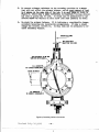
Jul y 18, 1963
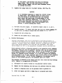
SERVICE BULLETIN NO. 3
Approved by FAA
Applies to FI2A-3, FL2A-4 cmd F12A-5 Propellers instolled on vcrious
Beech Model 33 Debonair cnd Model 35 Bonanzq Aircrqft
A smcll crqck hqs been found in the welded joint where the qft side of the hub bcrrel is joined
to the hydroulic cylinder. Such crqcks could leqd to serious oil loss.
(q) Within the next 25 hours of time in service ofter the effective dqte of this bulletin, cond
thereafter within each 100 hours' time in service, remove the propeller spinner and visuclly
inspect for crccks qnd oil leqks in the weld oreq where the qft side of the hub bcnrel is
joined to the hydrcrulic cylinder.
(b) At ecch propeller overhcul, inspect the hub by mcgnetic pcrticle inspection or FAA cpproved
equivclent method. Give pcnticulcr qttention to the weld where the qft side of the borrel
is joined to the hydrculic cylinder.
(") Reploce crqcked pcrts with new pcnts prior to further flight.
Note: Repcirs cre not permissible.
(d) This bulletin cpplies only to hubs with seriql numbers lower than 400.
:i:iiiiiii::i rififEil\t
::::::::::::::::::;::
rrLr-l_EKt
rffi"
i:+rirriii
li:iii;iir:iii:i:
iii:iliiiiiiiiii:
::iiii:i!:ii:ii
:iiii:i::tj:i:
:!:i:i:i:!:!:!:!:i:i!i
:::i:i:::::::::::::::i
:::::::i:::
iii:i:ii:iii
tt
t'
iii:iiiii:iii:iii::
it
,t
K\--,Kwwwwwwwwwwwwwwwwwwwwwwwwwwwwwwwwwwwwwwwwwwwwwwww#N\.-
lXiii
i i # i i i f f i . i i i i i i i i i i i:::::::::::::::i::::::::
i i i i i i i U l u c a g nFRoFELLER
Ancnlrtlnous7Rtgsi
PRoPELLER
:i:iii'"",
i|
:i':,i:::a:a:i.
,iii:i,i:,i:i
VNi\\\
f\\\\\\\\\\\\\\\\\
\\ \\\\\\\\\
iri:iliiilili:iii
U)$)\>>)X
utrt
J-i5ia-
iiiiiiii:liii:li:iSkyRonchAirport
at-.ttr-rraAJ
a
,uUU-tttt--
i:iii:i:i:i::i
::iiii:::i:ii:
DlvlsloN
DtvlstoN
ii:ii:ilii
:i:ii:ii:i:
Port OlficeBox5305,Dcnvcr,Colorodo-80217iliii:ii:ii
ii,f,ji,ii'i,iiiji,,,,,,,,,,,,,,,,,,,,,,,'HW,i;iiifi+
Jul y 18, 1963
SERVICE BULLETIN NO. 4
Approved by FAA
Applies to Fl2A-3, Fl2A-4 cnd Ft2A-5 Propellers instqlled on vcrious
Beech Model 33 Debonqir cnd Model 35 Bonqnza Aircrcrft
It hqs been found in mcny ccses impossible to clign the slot in the AN3IGS nut with the cotter
pin- hole in the pitch control cnm stud (item 5 in Figure I of Flottorp Model Fl2 Service Morucl)
within the specified torque r(mge (Figure 6 in the Mcnucl). Advcncing the nut results in shecring
the locking pin in the qrm. Bocking the nut off mcy eliminote the lorque entirely.
We recommendthqt, at next overhoul, the AN3l0-5 nuts cmd AN38I-2-L2 cotters on these two
studs be disccnded. Replqce with MS20365-524C(qll-metql) nuts. Torque to 70 to 80 inch-pounds.
{-
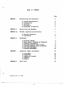
EABIE CE' CONIEIfTS
Fage
ffiMON
I
Speelflcattons
A.
B.
C.
D.
E.
and Deacrlptl.on.
C'eneral Speetflcatlons
fnsta.lLations
Governors
Deserlption
Prtoelples of Qrcratlon
2
2
2
2
3
3
surr@ rr
Servtce Tools and Eqtrltrment
h
SECITONIII
Perlodte
5
Inspection
aud LubrXcatton
A. Perlodie Inslrcctlon
B' Irrbrlcatlon
SHfION
NI
SffiBIST V
!{aintepa.nee
T
A.
B.
C.
D.
E.
F.
G.
T
T
7
I
I
I
Rev is e d
July
hopeller
&norral
l{lnotr Relntrl C.leanlng anal Inspeetlm
Insta$etlon
kolreller
Cheektug Prqgte$er Traek tn Sbnlt
Check{ng hopeller
Traek on Alreraft
Iov Plteh *dJnstneub
Governor l,falutensnee
Inspectlon,
A.
B.
C.
D.
E.
SECTION IN
,
6
Dteassenbl.y
Inslrcett on
Replr end Overbaul
Aesenb\r
Balauce
Parts Ltsts
10, 1962
Regatr and Orerhcul'
10
12
L2
L5
r7
1g
n
25