1
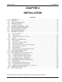
CPI Canada Inc. Installation 2 CHAPTER 2 INSTALLATION CONTENTS: INTRODUCTION ...................................................................................................................................... 2-3 2.1.0 2.2.0 RECEIVING .............................................................................................................................................. 2-3 2.2.1 Major Shipping Assemblies ................................................................................................................... 2-4 2.3.0 REMOVAL FROM PACK .......................................................................................................................... 2-4 2.3.1 Lifting The Generator ............................................................................................................................ 2-5 2.4.0 REMOVING THE EXTERNAL COVERS .................................................................................................. 2-6 2.5.0 LINE-ADJUSTING TRANSFORMER ....................................................................................................... 2-8 2.6.0 MAJOR COMPONENT LAYOUT .............................................................................................................. 2-8 2.7.0 INSPECTING THE HT TANK.................................................................................................................... 2-8 2.8.0 EQUIPMENT PLACEMENT ...................................................................................................................... 2-8 2.8.1 Equipment Cabinet ................................................................................................................................ 2-8 2.8.2 Control Console .................................................................................................................................... 2-8 2.8.3 Anchoring The Generator To The Floor .............................................................................................. 2-10 2.8.4 Leveling ............................................................................................................................................... 2-10 2.9.0 WIRING TO THE GENERATOR............................................................................................................. 2-10 2.9.1 Control Console .................................................................................................................................. 2-11 2.9.2 Remote Fluoro Control (Optional) ....................................................................................................... 2-14 2.9.3 Hand Switch Installation ...................................................................................................................... 2-14 2.9.4 X-Ray Tube Stator & Thermal Switch Connections ............................................................................ 2-17 2.9.5 Generator Mains Connection .............................................................................................................. 2-18 2.9.6 Room Equipment................................................................................................................................. 2-19 2.9.7 Emergency Power Off / Power Distribution Relay............................................................................... 2-19 2.10.0 X-RAY TUBE HOUSING GROUND ........................................................................................................ 2-19 2.11.0 HIGH TENSION CABLES ....................................................................................................................... 2-19 2.12.0 PROGRAMMING THE LOW SPEED STARTER .................................................................................... 2-21 2.12.1 Low Speed Starter Tube Select Table ................................................................................................ 2-21 2.12.2 Low Speed Starter Boost Voltage Selection ....................................................................................... 2-21 2.12.3 Low Speed Starter Run Voltage Selection .......................................................................................... 2-23 2.12.4 Low Speed Starter Boost Time Selection ........................................................................................... 2-24 2.13.0 PROGRAMMING THE DUAL SPEED STARTER................................................................................... 2-24 2.13.1 Setting tube type ................................................................................................................................. 2-24 2.13.2 Confirming/Changing DSS Starter Type ............................................................................................. 2-26 2.13.3 Dual Speed Starter Tube Select Table ............................................................................................... 2-27 2.13.4 Configuring dual speed starter 733317-15 / 735925-15...................................................................... 2-28 2.14.0 GENERATOR LOCKOUT SWITCH ....................................................................................................... 2-29 2.15.0 SAFETY INTERLOCKS .......................................................................................................................... 2-30 Use and disclosure is subject to the restrictions on the title page of this CPI document. Indico 100 Series Service Manual Ch # 740895-04 Rev. BU Page 2-1 2 Installation CPI Canada Inc. 2.16.0 CHECKING THE RAM BACKUP BATTERY VOLTAGE ......................................................................... 2-30 2.17.0 DIP SWITCH SETTINGS ........................................................................................................................ 2-32 2.18.0 INITIAL RUN-UP ..................................................................................................................................... 2-33 2.18.1 Initial Voltage Measurements .............................................................................................................. 2-33 2.18.2 Initial Power Up ................................................................................................................................... 2-34 2.18.3 Single Phase Primary Tap Selection ................................................................................................... 2-35 2.18.4 Three Phase Primary Tap Selection ................................................................................................... 2-37 2.19.0 PROGRAMMING AND CALIBRATION................................................................................................... 2-38 2.20.0 TUBE AUTO CALIBRATION................................................................................................................... 2-40 2.21.0 FINAL CHECKS ...................................................................................................................................... 2-42 Use and disclosure is subject to the restrictions on the title page of this CPI document. Page 2-2 Rev. BU Indico 100 Series Service Manual Ch # 740895-04 CPI Canada Inc. 2.1.0 Installation 2 INTRODUCTION This chapter contains instructions for unpacking, positioning, and cabling the Indico 100 series of generators to allow initial operation and calibration. The instructions in this chapter allows the installation engineer to: • Install the generator and control console. • Install the optional remote fluoro control. • Connect power. • Calibrate one or two X-ray tube(s), depending on the generator model, without completing the room interface connections. This allows for simpler installation and troubleshooting on the generator itself. 2.2.0 RECEIVING WARNING: THE INDICO 100 GENERATOR CONSISTS OF THE FOLLOWING ITEMS: UPPER AND LOWER CABINETS (FACTORY ASSEMBLED), CONTROL CONSOLE, AND AN OPTIONAL REMOTE FLUORO CONTROL. THE COMPLETE GENERATOR WEIGHS APPROXIMATELY 250 POUNDS (115 KG) IN ITS SHIPPING CONTAINER. THE OPTIONAL LINE ADJUSTING TRANSFORMER IS SUPPLIED IN A SEPARATE ENCLOSURE, THE WEIGHT OF THAT ASSEMBLY IS APPROXIMATELY 100 POUNDS (45 KG). THE OIL TANK IS LOCATED IN THE LOWER (POWER SUPPLY) CABINET. ONE PERSON SHOULD NOT ATTEMPT TO LIFT OR MOVE THE GENERATOR ASSEMBLY OR OPTIONAL LINE ADJUSTING TRANSFORMER WITHOUT ADEQUATE ASSISTANCE OR PROPER EQUIPMENT. Use and disclosure is subject to the restrictions on the title page of this CPI document. Indico 100 Series Service Manual Ch # 740895-04 Rev. BU Page 2-3 2 Installation 2.2.1 CPI Canada Inc. Major Shipping Assemblies Refer to figure 1A-1 and 1A-2 (chapter 1A). These figures show the generator cabinet fully assembled, along with the control consoles and optional remote fluoro control unit. 2.3.0 REMOVAL FROM PACK 1. Inspect the shipping pack(s) for evidence of shipping damage. If there is evidence of shipping damage, note this in the event that a damage claim is justified. 2. Locate any documentation attached to the outside of the cardboard sleeve for the generator pack. Be sure to read and understand this documentation before unpacking the generator. Then set this documentation aside temporarily until it can be transferred to a storage location close to the generator for future reference. 3. Remove the cardboard outer pack(s). CAUTION: OPEN THE CARDBOARD PACK(S) AND STRETCH WRAP PACKAGING CAREFULLY. SHARP TOOLS MAY DAMAGE THE CONTENTS. 4. Set aside the cardboard pack(s). 5. Remove and unpack the control console, any cables packed with the generator, the optional remote fluoro control if used, and the optional hand switch kit if included. • Units equipped with a touchscreen console are shipped with the base as a separate component. Remove and unpack the base and check for any damage. 6. Unscrew the bolts that secure the generator to the shipping pallet. Carefully lift the generator from the pallet. Refer to 2.3.1 for the procedure for lifting the generator. 7. If applicable, unpack the optional line-adjusting transformer. 8. Inspect all items for shipping damage. Refer to 2.4.0 for instructions for removing the generator external covers. 9. Unscrew the leveling feet at the bottom of the generator by a minimum of 1 ½ in. (35 mm). This will provide the required airflow underneath the generator cabinet and allow room to make leveling adjustments when the generator is placed in its final location. NOTE: SUPPORT THE CARDBOARD PACKS CONTAINING THE TOUCHSCREEN CONSOLE AND BASE COMPONENTS WHEN REMOVING THE STRETCH WRAP PACKAGING. PRODUCT DAMAGE OR PERSONAL INJURY MAY OCCUR IF THESE ARE NOT SUPPORTED. 10. Remove and unpack the manuals and any other paperwork that may be packed with the generator. 11. Keep the shipping containers. In case of shipping damage, place the unit(s) back in their shipping pack(s) and notify the carrier and the customer support group at CPI Canada Inc. Use and disclosure is subject to the restrictions on the title page of this CPI document. Page 2-4 Rev. BU Indico 100 Series Service Manual Ch # 740895-04 CPI Canada Inc. 2.3.1 Installation 2 Lifting The Generator One of the following methods is recommended for lifting or maneuvering the generator. Since the generator weighs more that 30 kg (65 lbs), proper lifting equipment should be used or additional help should be obtained to lift the unit. Refer to figure 2-2 for identification of the panels referenced below. • Lifting straps can be used along with a hoist to raise the generator. The straps should be placed underneath the generator cabinet and along the four sides to properly support the cabinet as it is raised. • Remove the main access panel and the lower wiring access panel from the generator cabinet. Refer to 2.4.0 for instructions for removing the external covers. The metal cross brace found at the front of the cabinet (below the circuit board mounting panel) may be used, in conjunction with the lip at the upper edge of the opening for the lower wiring access panel, as lifting points. Two people (one on each side) will be required to lift or maneuver the generator cabinet. Figure 2-1: Generator lifting points Use and disclosure is subject to the restrictions on the title page of this CPI document. Indico 100 Series Service Manual Ch # 740895-04 Rev. BU Page 2-5 2 Installation 2.4.0 CPI Canada Inc. REMOVING THE EXTERNAL COVERS NOTE: A POTENTIAL HAZARD EXISTS TO OPERATORS, SERVICE PERSONNEL, OR TO THE EQUIPMENT IF THE GENERATOR IS OPERATED WITH ANY OF THE GROUND LEADS TO THE EXTERNAL COVERS DISCONNECTED OR IMPROPERLY CONNECTED. BE SURE TO PROPERLY RECONNECT ALL GROUND LEADS AFTER COMPLETING ANY PROCEDURE THAT REQUIRES THEIR REMOVAL. REFER TO FIGURE 2-2 FOR IDENTIFICATION OF COVERS / PANELS DESCRIBED IN THIS SECTION. Upper Cabinet Hood Most generator service and adjustments can be performed by flipping back the hood. It is rarely necessary to completely remove the hood. However, both procedures are detailed below: Flipping back the hood Remove the upper wiring channel if fitted. The procedure for doing this is detailed later in 2.4.0. Remove screws A (four places, shown in figure 2-2) on both sides of the hood. Loosen screw B on both sides of the hood by 1-2 turns. Lift up on the front of the hood, allowing the hood to pivot on screws B. The hood should be supported when flipped open such that the hood does not exert excess pressure on the back of the cabinet. Removing the hood With the hood flipped back, disconnect the ground wire at the base of the upper cabinet. Lower the hood back to its normal position and remove the two upper screws (B in figure 2-2). Firmly grip the sides of the hood and slide the hood away from the rest of the cabinet. Be sure to properly re-connect the ground lead when the hood is replaced. Main Access Panel Flip back the upper cabinet hood as described above. This must be done before the main access panel can be removed. Then remove the screws that secure the main access panel to the generator cabinet (these screws are located on both sides of the main access panel). The panel may then be pulled away from the frame. Temporarily disconnect the ground lead connecting the panel to the cabinet, if necessary. Reverse the above steps to reconnect the ground wire(s), and to reinstall the access panel. Lower Wiring Access Panel THIS PANEL IS NOT FITTED IF THE OPTIONAL WIRING CHANNELS ARE USED. Remove the screw from the upper right hand corner of the panel. Pull out the snaps on the three nylon fasteners such as to release the panel. Remove the panel from the generator. Use and disclosure is subject to the restrictions on the title page of this CPI document. Page 2-6 Rev. BU Indico 100 Series Service Manual Ch # 740895-04 CPI Canada Inc. 2.4.0 Installation 2 REMOVING THE EXTERNAL COVERS (Cont) Upper & Lower Wiring Channels The wiring channels are optional. If the wiring channels are fitted, the lower wiring access panel will not be used. To remove the lower wiring access panel, remove the screws from the upper left and upper right corner of the panel to be removed. Then slide the wiring channel up such that the shoulder rivets clear the keyhole slot at the bottom of the channel. The wiring channel may then be removed from the generator. To remove the upper wiring access panel, remove the screws from the upper left and upper right corner of the panel. Then pull out the snaps on the nylon fasteners at the bottom corners of the panel. The wiring channel may then be removed. Figure 2-2: Removable external covers on generator cabinet Use and disclosure is subject to the restrictions on the title page of this CPI document. Indico 100 Series Service Manual Ch # 740895-04 Rev. BU Page 2-7 2 Installation 2.5.0 CPI Canada Inc. LINE-ADJUSTING TRANSFORMER An optional line-adjusting transformer is available if required to allow 480 VAC generators to operate from 400 VAC mains, or to allow 400 VAC generators to be operated from 480 VAC mains. The line-adjusting transformer is supplied in a separate enclosure. Please consult the factory for further details regarding this option. 2.6.0 MAJOR COMPONENT LAYOUT Refer to chapter 1E for major component identification and layout. 2.7.0 INSPECTING THE HT TANK Before continuing with the installation of the generator, the HT tank should be inspected as per the following steps: • Verify that there is no obvious shipping damage to the tank (i.e. dents to the tank surface). • Carefully check the inside of the generator cabinet and the HT tank for evidence of any oil loss. Refer to chapter 6 if it is suspected that there has been some loss of oil. • Verify that the clamps supporting the HT oil tank are tight. • Verify that all the connections to the tank lid are secure. • Verify that the rubber vent plug on the top of the tank is snug (not fitted on all models). • Ensure the vent hole is not blocked (not fitted on all models). 2.8.0 EQUIPMENT PLACEMENT 2.8.1 Equipment Cabinet Place the equipment cabinet in a location that will allow the following: • Easy front and side access for service and sufficient clearance at the rear for room interface cables. Refer to chapter 1C. • Air circulation - a minimum height of 1 ½ in. (35 mm) is recommended to allow airflow underneath the generator. Do not cover or block the cooling slots on the cabinet. • Stable footing - the leveling feet at the bottom of the cabinet will be used to prevent movement during normal operation. • Close proximity to service disconnect boxes - cables should not be on the floor where they could be stepped on. 2.8.2 Control Console Membrane Console Locate the control console in its intended position and ensure that it is stable. Refer to chapter 1C: • The control console (membrane console, touchscreen console, or mini-console) must be located inside an X-ray shielded control booth within the X-ray room, or outside the X-ray room. • If the console is located on a shelf, supply index pins or equivalent hardware to the base of the console to prevent slipping. • Ensure that the console is mounted at a height and angle to allow easy viewing of the displays. • If the optional CPI pedestal stand is to be used for the console mounting, follow the mounting instructions supplied with the stand. • Leave sufficient slack in the cabling to the console to allow for future service and maintenance. Use and disclosure is subject to the restrictions on the title page of this CPI document. Page 2-8 Rev. BU Indico 100 Series Service Manual Ch # 740895-04 CPI Canada Inc. 2.8.2 Installation 2 Control Console (Cont) The following steps apply to the Rad-only console. In some jurisdictions, regulations demand that the console PREP and EXPOSE buttons be disabled if a hand switch assembly is being employed. This is done by removing JW1 and JW2 from the Rad-only console board. 1. 2. 3. 4. 5. Turn the console upside down and place on a clean, non-abrasive surface. Remove and set aside the hardware from the console ground stud and the six screws securing the base to the molded case. Remove the console bottom (the metal bottom panel with the feet attached). Locate and remove JW1 and JW2. Refer to figure 1E-4 for location of JW1 and JW2. Reassemble the console using all the original hardware. Touchscreen Console The touchscreen base is shipped as a separate component and must be attached to the touchscreen console before being wired to the generator. A hex key has been included to adjust the tension on the tilt arm mechanism. A Phillips screwdriver is required to attach the base to the touchscreen console. 1. Carefully unpack the touchscreen console and the desk-mount base components and set the packaging aside. Verify that all components are present and undamaged. Note: To avoid damage to the LCD touch sensitive display, place the touchscreen console on a FLAT, CLEAN, NONABRASIVE surface. 2. There are two sets of VESA (Video Equipment Standards Association) mounting holes on the back plate and on the touchscreen console. One set is spaced at 100 mm and the other set is spaced at 75 mm. CPI recommends the use of the 100 mm spaced VESA holes. Line up the back plate with the touchscreen (observe orientation). Attach the base using the screws provided. See figure 2-3. 100mm(3.94") 100mm(3.94") 75mm(2.95") 75mm(2.95") Figure 2-3: Touchscreen base back plate showing VESA mounting holes Use and disclosure is subject to the restrictions on the title page of this CPI document. Indico 100 Series Service Manual Ch # 740895-04 Rev. BU Page 2-9 2 Installation 2.8.2 NOTE: CPI Canada Inc. Control Console (Cont) THE SET SCREW COLLAR MUST BE SECURED ON THE UPPER HALF OF THE TILT ARM TO PREVENT PERSONAL INJURY SHOULD THE TOUCHSCREEN SLIP WHILE ADJUSTING THE VIEWING HEIGHT. ADJUST THE SET SCREW COLLAR (FIGURE 2-5) USING THE PROVIDED HEX KEY BEFORE ADJUSTING THE HEIGHT OF THE TOUCHSCREEN CONSOLE. THE SET SCREW COLLAR MUST BE POSITIONED SUCH THAT THERE IS NO LESS THAN 25mm (1 inch) OF CLEARANCE BETWEEN THE BOTTOM EDGE OF THE TOUCHSCREEN CONSOLE AND THE TOUCHSCREEN BASE PLATE WHEN THE TOUCHSCREEN IS ADJUSTED TO ITS MINIMUM HEIGHT. PLEASE BE SURE TO SUPPORT THE TOUCHSCREEN CONSOLE WHEN ADJUSTING ITS VIEWING POSITION. NOTE: DO NOT LOCATE THE CONTROL CONSOLE WHERE X-RADIATION MAY BE PRESENT DURING INSTALLATION OR OPERATION. NOTE: IT IS RECOMMENDED THAT THE CONSOLE CABLE NOT BE DISASSEMBLED FOR SYSTEM INSTALLATION. HOWEVER, IF THIS IS ABSOLUTELY NECESSARY TO ROUTE THE CABLE, PLEASE ENSURE CAREFUL AND CORRECT REASSEMBLY OF THE CONNECTOR SHELL TO AVOID ANY POSSIBILITY OF PINCHING OF THE INTERNAL WIRES BY THE SHELL. YOU MAY CHOOSE TO TEMPORARILY LOCATE THE CONSOLE NEAR THE GENERATOR FOR INITIAL PROGRAMMING AND CALIBRATION. IF THIS IS SO, PLEASE COMPLETE THE FINAL CONSOLE INSTALLATION PER THIS SECTION WHEN THE GENERATOR INSTALLATION IS COMPLETED. 2.8.3 Anchoring The Generator To The Floor If it is desired to anchor the generator to the floor, refer to chapter 1C. This should not be done until all cable hookups are completed that require rear access to the generator. 2.8.4 Leveling Adjust the leveling feet such that the generator is level and stable. This adjustment must be made for both anchored and freestanding generator installations. As noted earlier, the leveling feet must be unscrewed by a minimum of 1 ½ in. (35 mm) to allow for proper airflow underneath the generator. 2.9.0 WIRING TO THE GENERATOR Ferrules should be used on the ends of all stranded wires that are connected to terminal connections in the generator. These must be supplied by the installer. Use and disclosure is subject to the restrictions on the title page of this CPI document. Page 2-10 Rev. BU Indico 100 Series Service Manual Ch # 740895-04 CPI Canada Inc. 2.9.1 Installation 2 Control Console DO NOT CONNECT UNAPPROVED EQUIPMENT TO THE REAR OF THE CONSOLE. For the 23 X 56 (cm) console, J5 is used for the interconnect cable to the generator main cabinet, J4 is not used, J2 is a serial port for use by an external computer, and J1 is for connection of an optional printer. For the 31 X 42 (cm) console, J5 is used for the interconnect cable to the generator main cabinet, J2 is a serial port for use by an external computer, and J13 is for connection of an external hand switch and / or foot switch. For the Rad-only console, J3 is for connection of an external hand switch, J4 is a serial port for use by an external computer, and J8 is for the interconnect cable to the generator main cabinet. For the touchscreen console, GEN on the rear of the touchscreen console is for the interconnect cable to the generator main cabinet, HS is for connection of an external hand switch, COM 1 and COM 2 are serial ports for use by external devices, LO (3.5 mm stereo jack) is for customer supplied speakers (minimum 8 ohms, do not use externally amplified speakers), ETH is a standard 10/100 ethernet connection, USBA and USBB are USB ports for connection of external devices, CF is for the compact flash memory card which holds the touchscreen software and SW1 is the console upgrade button. INCORRECT CONNECTIONS OR USE OF UNAPPROVED EQUIPMENT MAY RESULT IN INJURY OR EQUIPMENT DAMAGE. Membrane Console 1. For the 23 X 56 (cm) console and the 31 X 42 (cm) console route the generator end of the console cable into the generator cabinet via the access cover in the upper part of the cabinet nearest to J4 on the generator interface board. For the Rad-only console, note the protective cover connected to the console cable. This is intended to protect the console cable connectors during shipping and routing of the console cable during installation. Disconnect the generator end of the cable (the end with the ferrite bead) from the protective cover, and then route the free end of the cable (with the protective cover attached) as required. Remove and discard the protective cover when finished. After removing the protective cover, inspect the console cable connectors for any and all damage. Please see figure 2-4 for an example of such damage. 2. For the 23 X 56 (cm) console and the 31 X 42 (cm) console, connect the console cable to J4 on the generator interface board. For the Rad-only console, connect the generator end of the console cable to J16 on the generator interface board. 3. Connect the free end of the console cable as follows: For the 23 X 56 (cm) console and the 31 X 42 (cm) console, connect the free end of the console cable to J5 at the rear of the console. For the Rad-only console, connect the free end of the console cable to J8 at the rear of the console. Ensure that the screw locks are fully tightened to secure the connectors. Use and disclosure is subject to the restrictions on the title page of this CPI document. Indico 100 Series Service Manual Ch # 740895-04 Rev. BU Page 2-11 2 Installation 2.9.1 CPI Canada Inc. Control Console (Cont) Figure 2-4: Console cable connector damage example Touchscreen Console: 1. Route the generator end of the console cable into the generator cabinet via the access cover in the upper part of the cabinet nearest to J4 on the generator interface board. Connect the generator end of the console cable to J4 on the generator interface board. 2. Connect the free end of the console cable to GEN on the rear of the touchscreen console. Ensure that the screw locks are fully tightened to secure the connectors. 3. Connect one end of the supplied ground wire to the touchscreen console ground screw, shown in figure 2-5. Connect the other end of the ground wire to the ground stud on the inside rear of the generator control chassis (“chassis ground” in figure 2-2). Note that this ground wire is required for EMC compliance only. It has no safety impact. 4. Optional: Connect the customer-supplied speakers (minimum 8 ohms) to LO (3.5 mm stereo jack) on the rear of the touchscreen console (do not use externally amplified speakers). Use cable ties to secure the speaker cable to the console cable for support. Pins 1 and 2 (left and right) of the 3.5 mm male stereo jack must be shorted together at the speaker end. Please note that connecting external speakers will disable one of the on-board touchscreen speakers. Figure 2-5 shows the designations and functions of the connectors on the rear panel of the control console. Use and disclosure is subject to the restrictions on the title page of this CPI document. Page 2-12 Rev. BU Indico 100 Series Service Manual Ch # 740895-04 CPI Canada Inc. 2.9.1 Installation 2 Control Console (Cont) Figure 2-5: Rear of control console Use and disclosure is subject to the restrictions on the title page of this CPI document. Indico 100 Series Service Manual Ch # 740895-04 Rev. BU Page 2-13 2 Installation 2.9.2 CPI Canada Inc. Remote Fluoro Control (Optional) Warning: ALWAYS DISCONNECT THE MAINS POWER BEFORE CONNECTING THE REMOTE FLUORO CONTROL BOX TO THE GENERATOR. IF THE MAINS POWER IS ON WHEN THE REMOTE FLUORO CONTROL BOX IS BEING CONNECTED, A SHORT CIRCUIT CAN OCCUR AND DAMAGE THE REMOTE FLUORO CONTROL BOX. 1. Connect the free end of the 9-conductor remote fluoro cable (from the optional remote fluoro control box) to J11 of the generator CPU board. Ensure that the screw locks are fully tightened to secure the connector. Refer to figure 2-6 for the location of J11 on the generator CPU board. The cable should be routed into the generator via the access cover in the upper part of the cabinet closest to J11 on the generator CPU board. Figure 2-6: Remote fluoro connector on generator CPU board 2.9.3 Hand Switch Installation FOR 23 X 56 (CM) CONSOLES: The optional hand switch is supplied as a kit that must be user installed. If this option is used, refer to separate installation instructions packaged along with the hand switch. For reference, a drawing is supplied in this section showing the hand switch connections to the console CPU board. See figure 2-7. Use and disclosure is subject to the restrictions on the title page of this CPI document. Page 2-14 Rev. BU Indico 100 Series Service Manual Ch # 740895-04 CPI Canada Inc. Installation 2 Figure 2-7: Hand switch connections on console CPU board Use and disclosure is subject to the restrictions on the title page of this CPI document. Indico 100 Series Service Manual Ch # 740895-04 Rev. BU Page 2-15 2 Installation 2.9.3 CPI Canada Inc. Hand Switch Installation (Cont) FOR 31 X 42 (CM) CONSOLES, RAD-ONLY CONSOLES, AND TOUCHSCREEN CONSOLES: The optional hand switch, if ordered from CPI Canada Inc, is supplied pre-wired to a male 9-pin subminiature ‘D’ connector. This connects to J13 on the rear of the 31 X 42 cm console, to J3 on the rear of the Rad-only console, or to HS on the rear of the touchscreen console. Fluoro foot switch connections may also be made to this connector (31 X 42 cm console with fluoro option only). For the touchscreen console, the fluoro foot switch connections must be made to the room interface board as per chapter 3B. The table below shows the pin designations for the hand switch connector on the console. A male 9-pin subminiature ‘D’ connector will need to be provided by the installer if the CPI supplied hand switch is not used. PIN NUMBER J13 PIN CONNECTIONS 31 X 42 CM CONSOLE J3 PIN CONNECTIONS RAD-ONLY CONSOLE AND HS PIN CONNECTIONS TOUCHSCREEN CONSOLE 1 2 3 4 5 Hand Switch: X-Ray No Connection Hand Switch: Prep No Connection Hand Switch: Common (ground) No Connection Foot Switch: ‘live’ terminal No Connection Foot Switch: ‘ground’ terminal Hand Switch: X-Ray No Connection Hand Switch: Prep No Connection Hand Switch: Common (ground) 6 7 8 9 NOT USED NOT USED NOT USED NOT USED Use and disclosure is subject to the restrictions on the title page of this CPI document. Page 2-16 Rev. BU Indico 100 Series Service Manual Ch # 740895-04 CPI Canada Inc. 2.9.4 Installation 2 X-Ray Tube Stator & Thermal Switch Connections Refer to figure 2-8 for the X-ray tube stator and thermal switch connections. 1. Route the X-ray tube stator cable(s) through the lower wiring access panel on the rear of the generator cabinet, then route the cables towards the stator terminal blocks as shown in the figure below. FOR UNITS WITH A LOW SPEED STARTER, SHIELDED STATOR CABLES ARE RECOMMENDED. FOR UNITS WITH A DUAL SPEED STARTER, SHIELDED STATOR CABLES MUST BE USED. THE SHIELD FOR THE STATOR CABLE(S) MUST BE PROPERLY GROUNDED AT BOTH THE TUBE END AND THE GENERATOR END OF THE CABLE(S). SEE FIGURE 2-8 FOR GROUNDING AT THE GENERATOR END. NOTE: 2. Connect the wires to the appropriate terminal as shown. The tube thermal switch will normally be connected to the THERMAL SWITCH connections on the stator terminal block, but may optionally be connected to the room interface board (refer to chapter 3B). 3. Ensure that all terminal connections are tight, then dress and secure the cables. ONE TUBE ONLY GENERATORS WILL HAVE 1 STATOR TERMINAL BLOCK FITTED. THE LOWER TERMINAL BLOCK IN FIGURE 2-8 IS ONLY FITTED ON TWO TUBE GENERATORS. Figure 2-8: Stator connections to generator Use and disclosure is subject to the restrictions on the title page of this CPI document. Indico 100 Series Service Manual Ch # 740895-04 Rev. BU Page 2-17 2 Installation 2.9.5 CPI Canada Inc. Generator Mains Connection WARNING: TO AVOID ELECTRICAL SHOCK, ENSURE THAT THE AC MAINS DISCONNECT IS LOCKED IN THE OFF POSITION, AND THAT ALL MAINS CABLES ARE DE-ENERGIZED BEFORE CONNECTING TO THE GENERATOR. Refer to chapter 1C for generator power and generator power line requirements. 1. Pass the AC mains cable through the access hole located at the lower rear of the generator. 2. Use an appropriate cable clamp to secure the mains cable at the cabinet entrance. 3. Temporarily remove the safety cover from the main fuses. Strip sufficient cable jacket to allow the ground wire to reach the main ground connector located at the left side of the main fuse block. Refer to figure 2-9. 4. Connect the ground wire to the main ground connector, and connect the mains wires to the terminals on the bottom of the main fuse holder (3 wires for 3 phase systems, 2 wires for single phase systems). Be sure to replace the main fuse safety cover after all connections are made and properly tightened. • Ferrules should be used on the ends of the AC mains wires. These must be supplied by the installer. • For China only, the power cable must be CCC approved 5. DO NOT SWITCH ON MAINS POWER AT THIS TIME. Figure 2-9: Generator mains connections Use and disclosure is subject to the restrictions on the title page of this CPI document. Page 2-18 Rev. BU Indico 100 Series Service Manual Ch # 740895-04 CPI Canada Inc. 2.9.6 Installation 2 Room Equipment Refer to chapter 3B, 3D, 3E, and 3F for connection of the room equipment (Buckys, miscellaneous inputs and outputs, AEC devices, digital imaging systems, DAP, etc.). It is suggested that these items not be connected until after the initial run-up of the generator is complete, and the tube auto calibration has been performed as described near the end of this chapter. 2.9.7 Emergency Power Off / Power Distribution Relay To connect an external emergency power-off switch, disconnect the jumper from J17-1 to J17-2 on the generator interface board. Then connect the emergency-off switch to J17-1 and J17-2. Refer to MD-0762 in chapter 9. For installations where installer-supplied auxiliary power distribution circuits are added to the generator, 24 VDC is available on the generator interface board to drive the coil of the power distribution relay. Connect the coil to J17-3 (+) and J17-4 (ground). Refer to MD-0788 in chapter 9. The maximum current available from this source is 100 mA. 2.10.0 X-RAY TUBE HOUSING GROUND 2 A separate ground wire (10 AWG, 6mm ) must be connected from each X-ray tube housing to one of the ground studs on the HT tank. Refer to figure 2-9 or 2-10. These ground locations may have other ground wires already connected, ensure that these existing ground wires are not disconnected when making the X-ray tube ground connection. Failure to make this ground connection may result in intermittent operation and/or exposure errors. 2.11.0 HIGH TENSION CABLES The X-ray tube(s) should be mounted on their normal fixtures i.e. tube stand, G.I. table or other devices. 1. Verify that the HT cable terminations are clean, in good condition i.e. no cracks, and coated with vapor proof compound. The contact pins must be opened sufficiently to make good contact with the mating connector in the HT tank. 2. Remove the plastic caps that cover the high voltage terminals on the HT tank. These should be saved in case of a future requirement to transport the generator or HT tank. 3. Connect the high-tension cables as per the installation requirements. Ensure that the cables for tube 1 (and tube 2 if used) are plugged into the proper connectors on the HT tank. Refer to figure 2-10 and 2-11. 4. Be sure that the HT cable connectors are tight and there is no play between the connector insulator and the screw down ring. Use and disclosure is subject to the restrictions on the title page of this CPI document. Indico 100 Series Service Manual Ch # 740895-04 Rev. BU Page 2-19 2 Installation CPI Canada Inc. 2.11.0 HIGH TENSION CABLES (cont) Figure 2-10: HV connectors (1 tube tanks) Figure 2-11: HV connectors (2 tube tanks) NOTE: PLEASE OBSERVE THE FOLLOWING IF USING METAL CENTER SECTION X-RAY TUBES The mA feedback signals, as measured at the mA test points on the control board, represent anode mA. X-ray emission in the tube is a result of the anode current. The mA measured at terminals E17 - E18 of the HT tank is cathode current. In a metal center section tube, the anode current will be less than the cathode current, the difference being body current. In a metal center section tube, the cathode current may exceed the anode current by up to 15%. Although the anode and cathode currents may be unequal, the anode to cathode kV regulation is not affected. Due to the presence of body current, filament drive and emission may need to be greater than expected for a given mA station. The power “lost” to body current may need to be considered relative to the maximum generator output. When installing a metal center section tube, it is essential that the center section of the X-ray tube be securely grounded; otherwise, premature tube failure may result. Use and disclosure is subject to the restrictions on the title page of this CPI document. Page 2-20 Rev. BU Indico 100 Series Service Manual Ch # 740895-04 CPI Canada Inc. Installation 2 2.12.0 PROGRAMMING THE LOW SPEED STARTER This section applies only to units fitted with the low speed starter. PLEASE BE SURE TO READ AND UNDERSTAND THIS SECTION FULLY BEFORE PROCEEDING. Before continuing, note the part number of the low speed starter in the generator. Part number 732752-00 has 30 µF phase-shift capacitance; part number 732752-01 has 12.5 µF phase-shift capacitance; part number 732752-02 has 45 µF phase-shift capacitance and part number 732752-04 has 100 µF phaseshift capacitance. Confirm that the phase shift capacitor(s) are compatible with the desired tube(s) as listed in table 1 in supplement 746026, which follows chapter 2. The starter boost voltage is set to approximately 240 VAC, (except where specifically noted in table 1 in supplement 746026), and the starter run voltage is selectable to be 52, 73, or 94 VAC. Boost times are selectable to be either 1.5 seconds, or 2.5 seconds. Therefore, the generator may be configured to be compatible with stator types as per table 1 in supplement 746026. If the desired tube type is not listed, please contact CPI product support for assistance. WARNING: 240 VAC IS PRESENT ON THE LOW SPEED STARTER BOARD AT ALL TIMES THAT THE GENERATOR IS SWITCHED ON. TAKE APPROPRIATE PRECAUTIONS WHEN SERVICING THIS BOARD 2.12.1 Low Speed Starter Tube Select Table See supplement 746026, which immediately follows this chapter. 2.12.2 Low Speed Starter Boost Voltage Selection THIS APPLIES TO ONE-TUBE GENERATORS ONLY. Follow the steps below to verify and configure the correct low speed starter boost voltage. 1. Confirm the required BOOST VOLTAGE for the selected tube type per table 1 in supplement 746026. The requirement for the vast majority of tubes in table 1 is 240 V. For tubes that require 120 V boost, this is noted along with the run voltage, boost time, etc for that tube. • Refer to figure 2-11 (power supply auxiliary transformer). Locate this transformer under the power input board; refer to chapter 1E for details. • If there is only one connection on the 120V tap on the power supply auxiliary transformer, the boost voltage is set to 240 VAC. • If there are two connections on the 120V tap, the boost voltage is set to 120 VAC. • Confirm the correct boost voltage at F1 on the low speed starter board with a suitable voltmeter. • Go to 2.12.3 if the boost voltage is properly set for the selected tube type and therefore does NOT need to be changed. Use and disclosure is subject to the restrictions on the title page of this CPI document. Indico 100 Series Service Manual Ch # 740895-04 Rev. BU Page 2-21 2 Installation CPI Canada Inc. 2.12.2 Low Speed Starter Boost Voltage Selection (Cont) THIS APPLIES TO ONE-TUBE GENERATORS ONLY. 2. If the boost voltage tap on the power supply auxiliary transformer needs to be changed from 240V to 120V, proceed as follows: • Loosen the clamping screws for the 240V tap and for the 120V tap. • Move the boost voltage lead from the 240V tap to the 120V tap. The boost voltage lead is the lead that connects directly to J1 on the low speed starter board. Do not disturb the other leads on the 120V and / or 240V taps. • Ensure that the wires are positioned between the two metal clamps on the transformer terminal block. • Retighten both of the clamping screws. • Confirm the correct boost voltage at F1 on the low speed starter board with a suitable voltmeter. 3. If the boost voltage tap on the power supply auxiliary transformer needs to be changed from 120V to 240V, proceed as follows: • Loosen the clamping screws for the 120V tap and for the 240V tap. • Move the boost voltage lead from the 120V tap to the 240V tap. The boost voltage lead is the lead that connects directly to J1 on the low speed starter board. Do not disturb the other leads on the 120V and / or 240V taps • Ensure that the wires are positioned between the two metal clamps on the transformer terminal block. • Retighten both of the clamping screws. • Confirm the correct boost voltage at F1 on the low speed starter board with a suitable voltmeter. Use and disclosure is subject to the restrictions on the title page of this CPI document. Page 2-22 Rev. BU Indico 100 Series Service Manual Ch # 740895-04 CPI Canada Inc. Installation 2 2.12.3 Low Speed Starter Run Voltage Selection Follow the steps below to verify and configure the correct low speed starter run-voltage. 1. Note the required RUN VOLTAGE for the selected tube type per table 1 in supplement 746026, which follows chapter 2. Then confirm the low speed starter run-voltage in the generator. This is determined by the run-voltage setting on the power supply auxiliary transformer. Refer to figure 212. • Locate this transformer under the power input board; refer to chapter 1E for details. • Locate the run-voltage output on the transformer. This will be set to the 52V, 73V, or 94V tap, and must match the required run-voltage for the selected tube in table 1. • Go to 2.12.4 if the run-voltage setting is correct for the selected tube type, and therefore does NOT need to be changed. 2. If the run-voltage setting on the power supply auxiliary transformer needs to be changed, proceed as follows: • Loosen the clamping screws for the current run-voltage tap, and for the required run-voltage tap. • Move the run-voltage output lead from the current tap position to the required tap position (52V, 73V, or 94V). Ensure that the wire is positioned between the two metal clamps on the transformer terminal block. • Retighten both of the clamping screws. Figure 2-12: Low speed run-voltage tap selection Use and disclosure is subject to the restrictions on the title page of this CPI document. Indico 100 Series Service Manual Ch # 740895-04 Rev. BU Page 2-23 2 Installation CPI Canada Inc. 2.12.4 Low Speed Starter Boost Time Selection Follow the steps below to verify and configure the low speed starter boost time. 1. Confirm the current low speed starter boost time selection: • Locate jumper JW1 on the auxiliary board. Refer to chapter 1E for the board location. • Confirm that the current boost time setting matches the tube in use: Jumper position “1.5S” = 1.5 second boost, no jumper at JW1 = 2.5 second boost. Do not use the “.15S” position. 2. If required, adjust the boost time by changing the JW1 jumper position as described above. NOTE: CONFIRM PROPER LOW SPEED STARTER CONFIGURATION USING A SUITABLE TACHOMETER BEFORE MAKING ANY EXPOSURES. 2.13.0 PROGRAMMING THE DUAL SPEED STARTER This section applies only to units fitted with the dual speed starter option. The dual speed starter must be programmed for the X-ray tube type(s) used at this site. This is done via DIP switches SW1 and SW2 on the dual speed starter. The following tube functions are set with these switches: • High speed start and run voltages • Low speed start and run voltages • Brake time and brake voltage (high speed) • Boost times • Boost time increments. Boost time may be increased in 100 ms steps in the range of 100 to 700 ms SW1 and SW2 on the dual speed starter must be set correctly to match the X-ray tube(s) in use. Failure to set these correctly may result in improper anode RPM and therefore may damage the X-ray tube. PLEASE BE SURE TO READ AND UNDERSTAND THIS SECTION FULLY BEFORE PROCEEDING. 2.13.1 Setting tube type 1. Select the desired tube type from table 2 in supplement 746026, which follows chapter 2. Record the tube type number (housing and insert) and the binary code as per the third column in the table. Please note that the tube compatibility applies only to the housing and inserts listed, i.e. for the specific manufacturer(s) shown. 2. If the desired tube type is not listed, please contact CPI product support for assistance. 3. Several dual speed starters are available, each configured to support one or more types of stators. Only stators of the type(s) supported by the dual speed starter currently installed may be used with this generator. REFER TO SECTION 2.13.2 IF IT IS DESIRED TO USE TUBES WITH STATOR TYPES NOT COMPATIBLE WITH THIS GENERATOR, OR IF YOU ARE NOT CERTAIN THAT THIS GENERATOR IS COMPATIBLE WITH THE STATOR IN YOUR TUBE. Use and disclosure is subject to the restrictions on the title page of this CPI document. Page 2-24 Rev. BU Indico 100 Series Service Manual Ch # 740895-04 CPI Canada Inc. Installation 2 2.13.1 Setting tube type (cont) 4. Refer to figure 2-13. Set the DIP switch SW1 (for tube 1) with the binary code for the selected tube. The binary code shown in the table programs the tube type (housing and insert), for example housing type Varian Sapphire with standard “R” stator and inserts per table 2 in Supplement 746026, which follows chapter 2, requires SW1-1 to be set ON, SW1-2 OFF, SW1-3 ON, SW1-4 OFF and SW1-5 OFF. This programs the voltages, brake times, and boost times in table 2. Additionally, SW1-6 to SW1-8 may be set to give incremental increases in boost time over the preselected values (i.e. to run an older tube with worn bearings). For example, binary 000 gives zero increase, binary 001 gives 100 ms increase, binary 100 gives 400 ms increase, and binary 111 gives a 700 ms increase in boost time. SW1-6 represents bit 1, SW1-7 bit 2, and SW1-8 represents bit 3. EXAMPLE: Binary 100 = decimal 4 = 400 ms incremental boost time increase: 1 Bit 3 SW1-8 NOTE: 0 Bit 2 SW1-7 0 Bit 1 SW1-6 5. The example DIP switch setting shown in figure 2-13 is for the example in step 4 with an incremental increase in boost time of 200 ms. 6. If this is a two-tube installation, repeat steps 1 to 4 using DIP switch SW2 for the second tube. 7. Please confirm all settings using a suitable tachometer to ensure proper anode RPM before making any exposures. FOR TUBES WHERE “LOW SPEED OPERATION ONLY” IS INDICATED, THE DUAL SPEED STARTER MUST BE PROGRAMMED FOR LOW SPEED ONLY, AND WHERE “HIGH SPEED OPERATION ONLY” IS INDICATED, THE DUAL SPEED STARTER MUST BE PROGRAMMED FOR HIGH SPEED OPERATION ONLY. REFER TO THE TUBE SELECTION SECTION IN CHAPTER 3C FOR THE PROCEDURE TO DO THIS. THE EXAMPLE DIP SWITCH SHOWN IN FIGURE 2-12 IS REPRESENTATIVE OF ONE STYLE OF SWITCH ONLY. DEPENDING ON MANUFACTURER, YOUR DIP SWITCH STYLE MAY VARY. PLEASE NOTE THE ON/OFF POSITIONS CAREFULLY FOR YOUR UNIT. Use and disclosure is subject to the restrictions on the title page of this CPI document. Indico 100 Series Service Manual Ch # 740895-04 Rev. BU Page 2-25 2 Installation CPI Canada Inc. 2.13.1 Setting tube type (cont) Figure 2-13: DIP switches on dual speed starter 2.13.2 Confirming/Changing DSS Starter Type Note that some dual speed starters support more than one stator type via relays to switch the phase shift capacitors. The low speed and high speed phase-shift capacitors for the stator start winding must be matched to the desired stator type, for example the required high speed phase shift capacitor is 6 uF for “R” type stators and 7.5 uF for GE Maxiray type stators. Therefore, for example, a dual speed starter that does not provide 7.5 uF of high speed shift capacitance CANNOT drive a GE Maxiray type stator. Use the steps in this section to verify that the dual speed starter is compatible with the stator in the desired tube. 1. Record the part number of the dual speed starter assembly in the subject generator. This is printed on a label, near the top left side of the dual speed starter chassis, next to the ground label. Use and disclosure is subject to the restrictions on the title page of this CPI document. Page 2-26 Rev. BU Indico 100 Series Service Manual Ch # 740895-04 CPI Canada Inc. Installation 2 2.13.2 Confirming/Changing DSS Starter Type (Cont) 2. If it is desired to use a different tube from that shown in the compatible X-ray tubes section of the customer product description form, confirm that the desired tube (housing and insert) is listed in table 2 of Supplement 746026 which follows chapter 2, AND that one of the required dual speed starter part numbers for that tube per table 2 is the same as is fitted in your generator. 3. If the preceding steps confirm that the desired tube is fully compatible with the generator, you may proceed with setting the tube type as per section 2.13.1. 4. If in the preceding steps it is determined that the desired stator IS NOT compatible with the generator, the phase shift capacitors in the dual speed starter will need to be changed to match the requirements of the desired tube. Replacement capacitor kits are available to do this as noted in the next step. 5. Note the required H.S. SHIFT CAP. and L.S. SHIFT CAP. values, and the corresponding dual speed starter part number for the desired tube per table 2 in supplement 746026. Using those capacitor values, refer to table 2-1. From this table select the required conversion kit to convert to capacitors as required for the selected tube. The conversion kits are available through the factory/customer support. IF MAKING THE ABOVE CONVERSION, PLEASE BE SURE TO CHANGE THE PART NUMBER IDENTIFIED IN STEP 1 TO THE NEW CONFIGURATION USING AN INDELIBLE MARKER. THIS WILL ENSURE THAT CONFIGURATION CONTROL OF THE PRODUCT IS MAINTAINED. NOTE: DUAL SPD STARTER PART No REQUIRED TABLE 2-1 HIGH SPEED SHIFT CAP 733317-01 / 735925-01 733317-02 / 735925-02 733317-12 / 735925-12 733317-13 / 735925-13 733317-15 / 735925-15 733317-16 / 735925-16 733317-17 / 735925-17 6 uF 20 uF 6 uF / 7.5 uF 5 uF / 6 uF 3 uF / 6 uF 6 uF / 12.5 uF 5 uF / 12.5 uF LOW SPEED SHIFT CAP 31 uF 60 uF 36 / 37.5 uF 30 uF 15.5 / 28 uF 31 / 37.5 uF 30 / 37.5 uF CONVERSION KIT P/N 734424-00 734424-02 734424-12 734424-11 734424-11 734424-11 734424-11 CAPACITOR VALUES SHOWN IN TABLE 2 IN SUPPLEMENT 746026 ARE EQUIVALENT VALUES OF THE PHASE SHIFT CAPACITORS IN THE DUAL SPEED STARTER. FOR EXAMPLE, THE “-13” VERSION OF THE DUAL SPEED STARTER USES TWO 12.5 uF CAPACITORS AND ONE 25 uF CAPACITOR CONNECTED IN SERIES TO GIVE NOMINAL 5 uF FOR HIGH SPEED USE. THIS 5 uF CAPACITANCE IS CONNECTED IN PARALLEL WITH A 25 uF CAPACITOR TO GIVE 30 uF FOR LOW SPEED USE AS SHOWN IN THE TABLES. 2.13.3 Dual Speed Starter Tube Select Table See Supplement 746026, which immediately follows this chapter. Use and disclosure is subject to the restrictions on the title page of this CPI document. Indico 100 Series Service Manual Ch # 740895-04 Rev. BU Page 2-27 2 Installation CPI Canada Inc. 2.13.4 Configuring dual speed starter 733317-15 / 735925-15 Dual speed starter part number 733317-15 / 735925-15 is a special configuration in which the low-speed phase shift capacitors may be set to 15.5 uF or 28 uF. The 15.5 uF setting is intended for use in installations where low-speed operation of CGR (GE) Statorix tubes is required. The high-speed capacitance is automatically selected to either 3 uF or 6 uF according to the DIP switch setting. Refer to figure 2-14. In configuration “A”, (28 uF) two each of the leads are connected to the lower right capacitor. Thus, the capacitor is in-circuit in this configuration. Configuration “B” (15.5 uF) has one of the leads of this capacitor disconnected from the terminals of the adjacent capacitor, thus the capacitor is out of the circuit. • To change from configuration “A” to “B”, disconnect the lower lead from the adjacent capacitor as shown in figure 2-14, and connect it to the same terminal of the lower right capacitor. This removes the lower right capacitor from the circuit. • To change from configuration “B” to “A”, reconnect the lead between the two capacitors, as shown in figure 2-14. This connects the capacitor into the circuit. After the phase shift capacitors are correctly configured, set the DIP switches as follows: • Locate the desired tube(s) in table 2 of supplement 746026, which follows chapter 2. With dual speed starter 733317-15 / 735925-15 set to configuration “A”, this starter is compatible with all tubes requiring a 3 uF or 6 uF high-speed shift capacitor (unless indicated otherwise) and a 28, 30 or 31 uF low-speed shift capacitor. When set to configuration “B”, it is only compatible with tubes requiring a 3 uF or 6 uF high-speed shift capacitor (unless indicated otherwise) and a 15.5 uF low-speed shift capacitor. Set the DIP switches as per 2.13.1. CONFIGURATION “A” (28 uF for TOSHIBA STATOR) CAPACITOR IN-CIRCUIT DUAL SPEED STARTER BOARD CONFIGURATION “B” (15.5 uF for LOW-SPEED CGR STATOR) CAPACITOR OUT-OF-CIRCUIT DUAL SPEED STARTER BOARD IND100_007B.CDR Figure 2-14: Selection of phase shift capacitance Use and disclosure is subject to the restrictions on the title page of this CPI document. Page 2-28 Rev. BU Indico 100 Series Service Manual Ch # 740895-04 CPI Canada Inc. Installation 2 2.14.0 GENERATOR LOCKOUT SWITCH A safety lockout switch (S3) is provided on the generator interface board. When this switch is in the LOCKOUT position, the generator cannot be switched on either from the console or from the adjacent service switch S2 on the generator interface board. This prevents inadvertent switching on of the generator while it is being serviced. S3, the generator lockout switch, must be in the NORMAL position to enable switching the generator on. Refer to figure 2-15 for these switch locations. Figure 2-15: Location of lockout switch and local ON/OFF switches Use and disclosure is subject to the restrictions on the title page of this CPI document. Indico 100 Series Service Manual Ch # 740895-04 Rev. BU Page 2-29 2 Installation CPI Canada Inc. 2.15.0 SAFETY INTERLOCKS It is strongly recommended that the following two interlocks be wired to the generator before preparing to make any exposures: DOOR INTERLOCK The room door interlock switch must be wired to the generator before proceeding. Use configuration A or configuration B as described below, depending on the desired mode of operation. Configuration A This configuration inhibits new exposures if the room door is open. This does not interrupt exposures in process when the door is opened. The door interlock switch is connected to TB4-4 and TB4-5 on the room interface board. Configuration B This configuration inhibits new exposures if the room door is open, and stops fluoro exposures if the room door is opened during a fluoro exposure. One pole on the door interlock switch is connected to TB4-4 and TB4-5 on the room interface board. One side of the second pole on the door interlock switch connects to TB6-5 on the room interface board, and one side of the fluoro footswitch connects to TB6-6. The other side of the room interlock switch and the other side of the fluoro footswitch should be spliced together using a suitable insulated connector. This wires the door interlock switch and the fluoro footswitch in series across the remote fluoro exposure input terminals TB6-5 and TB6-6. Refer to MD-0763 in chapter 9. NOTE: THE INSTALLER MUST PROVIDE A VISUAL INDICATION OF THE ON/OFF STATE OF EACH EXTERNAL DEVICE THAT CAN PREVENT THE GENERATOR FROM EMITTING RADIATION, OR THAT CAN STOP THE GENERATOR FROM EMITTING RADIATION, OR BOTH. X-RAY TUBE THERMAL SWITCH The X-ray tube(s) thermal switch(s) should be connected to the generator for tube thermal protection. These may be connected either at the stator terminal blocks (section 2.9.4), or at the room interface board. The connections on the room interface board are TB4-8 and TB4-9 for tube 1, and TB4-6 and TB47 for tube 2. 2.16.0 CHECKING THE RAM BACKUP BATTERY VOLTAGE It is recommended that the backup battery voltage be checked before continuing. The normal life expectancy of these batteries is estimated at 5 years. CONSOLE CPU BOARD (23 X 56 cm console): 1. Turn the operator console upside down carefully to protect the front panel. Remove the six screws securing the base to the molded case. 2. Open the console carefully, such that the interconnecting cables are not strained. 3. Locate the battery on the console CPU board; refer to figure 2-16. Measure the battery voltage with a DVM. The top of the battery is the positive side; ground (TP2 on the board) is the negative side. 4. The nominal battery voltage should be approximately 3.0V; replace the battery if it is under 2.80V. Use and disclosure is subject to the restrictions on the title page of this CPI document. Page 2-30 Rev. BU Indico 100 Series Service Manual Ch # 740895-04 CPI Canada Inc. Installation 2 2.16.0 CHECKING THE RAM BACKUP BATTERY VOLTAGE (Cont) 5. Before closing the console, refer to the section DIP SWITCH SETTINGS in this chapter. 6. Re-assemble the console. DO NOT OVER TIGHTEN THE SCREWS SECURING THE BASE TO THE MOLDED CONSOLE TOP. CONSOLE BOARD (31 X 42 cm console and Rad-only console): The 31 X 42 cm and the Rad-only consoles use flash memory, which does not require a backup battery. GENERATOR CPU BOARD: 1. Locate the battery on the generator CPU board, refer to figure 2-16. Measure the battery voltage with a DVM. The top of the battery is the positive side; ground (TP21 on the board) is the negative side. 2. The nominal battery voltage should be approximately 3.0V, replace the battery if it is under 2.80V. CONSOLE CPU BOARD 23 X 56 CM CONSOLES TP2 GND GENERATOR CPU BOARD GND TP21 IN_BATT.CDR Figure 2-16: Location of battery on generator CPU board and on 23 X 56 cm console CPU board Use and disclosure is subject to the restrictions on the title page of this CPI document. Indico 100 Series Service Manual Ch # 740895-04 Rev. BU Page 2-31 2 Installation CPI Canada Inc. 2.17.0 DIP SWITCH SETTINGS Before continuing, verify the DIP switch settings on the console CPU board (23 X 56 cm console only) and on the generator CPU board. These switches have been factory set but may have been readjusted, particularly if this generator is a re-install. CONSOLE CPU BOARD (23 X 56 cm console): The selections described below are accessed in CONSOLE utilities screen 2 on the 31 X 42 cm console and on the Rad-only console. • Verify the settings on SW1 (If applicable, as described above). Refer to console utilities screen 2 in chapter 3C for a description of these functions. LANGUAGE English German French Italian Swedish Spanish SW1-5 SW1-6 SW1-7 SW1-8 SW1 -4 OFF OFF OFF OFF OFF OFF SW1-3 OFF OFF OFF OFF ON ON SW1-2 OFF OFF ON ON OFF OFF SW1-1 OFF ON OFF ON OFF ON NOT USED NOT USED OFF > LOGO NOT DISPLAYED ON > LOGO DISPLAYED OFF > CONSOLE DEFAULTS OFF * ON > LOAD CONSOLE DEFAULTS * GENERATOR CPU BOARD: • Verify the settings on SW1. Refer to the table below for the proper settings for this switch. GENERATOR POWER 32 kW 40 kW 50 kW 65 kW 80 kW 100 kW SW1-4 SW1-5 SW1-6 SW1-7 SW1-8 MAXIMUM mA 400 mA 500 mA 630 mA 800 mA 1000 mA 1000 mA SW1 -3 ON ON OFF OFF OFF OFF SW1-2 ON OFF ON ON OFF OFF SW1-1 OFF ON ON OFF ON OFF OFF > 2 FILAMENT BOARDS OFF > 150 kV MAXIMUM OFF > DUAL SPEED STARTER OFF > 2 TUBE GENERATOR ON > I FILAMENT BOARD ON > 125 kV MAXIMUM ON > LOW SPEED STARTER ON > 1 TUBE GENERATOR OFF > SET FACTORY DEFAULTS * ON > DEFAULTS DISABLED * * Refer to Resetting Factory Defaults in chapter 6 for details regarding this function. Use and disclosure is subject to the restrictions on the title page of this CPI document. Page 2-32 Rev. BU Indico 100 Series Service Manual Ch # 740895-04 CPI Canada Inc. Installation 2 2.18.0 INITIAL RUN-UP This section describes the procedure for initial power-on of the generator after it has first been installed. PLEASE OBSERVE THE FOLLOWING POINTS REGARDING THE MAIN DISTRIBUTION TRANSFORMER: • IF USING A DISTRIBUTION TRANSFORMER WITH AN ISOLATED SECONDARY, THE SECONDARY WINDING MUST BE A WYE (STAR) CONFIGURATION WITH THE CENTER POINT GROUND REFERENCED. DO NOT USE A DELTA CONFIGURED SECONDARY AS THERE IS NO GROUND REFERENCE IN THIS CONFIGURATION. • IF USING AN AUTOTRANSFORMER TYPE DISTRIBUTION TRANSFORMER, THE A.C. INPUT TO THE TRANSFORMER MUST BE GROUND REFERENCED. 2.18.1 Initial Voltage Measurements 1. Verify that the mains voltage and current capacity is correct for the generator installation. Refer to the product ID label on the generator cabinet and chapter 1C of this manual. 2. Temporarily remove the safety cover over the main input fuses in the generator. 3. If the mains supply is compatible with the generator, switch on the main breaker and/or disconnect switch and check for the following voltages: NOTE: DO NOT SWITCH ON THE GENERATOR AT THIS TIME. ONLY THE AC MAINS TO THE GENERATOR IS TO BE SWITCHED ON AT THIS TIME. WARNING: 1. USE EXTREME CARE IN MEASURING THESE VOLTAGES. ACCIDENTAL CONTACT WITH MAINS VOLTAGES MAY CAUSE SERIOUS INJURY OR DEATH. 2. MAINS VOLTAGE WILL BE PRESENT INSIDE THE GENERATOR CABINET, EVEN WITH THE CONSOLE SWITCHED OFF. 3. THE DC BUS CAPACITORS, LOCATED ON THE POWER INPUT BOARD AND ABOVE THE HT TANK ON SOME MODELS, PRESENT A SAFETY HAZARD FOR UP TO 5 MINUTES AFTER THE POWER HAS BEEN REMOVED FROM THE UNIT. CHECK THAT THESE CAPACITORS ARE DISCHARGED BEFORE TOUCHING ANY PARTS. PLEASE NOTE THAT THE VOLTAGE MEASURED IN STEP 4 WILL NOT NECESSARILY BE THE SAME AS THE VOLTAGE AT THE MAIN DISCONNECT BOX IN THE ROOM. THE REASON FOR THIS IS THAT A LINE ADJUSTING TRANSFORMER MAY BE USED WITH THE GENERATOR WHICH STEPS THE INCOMING LINE VOLTAGE TO THE GENERATOR UP OR DOWN. GENERATORS WITH NO LINE ADJUSTING TRANSFORMER SHOULD HAVE THE SAME VOLTAGE IN STEP 4 AS IS SUPPLIED AT THE MAIN DISCONNECT BOX IN THE ROOM. UNITS WITH A LINE ADJUSTING TRANSFORMER SHOULD HAVE THE FOLLOWING VOLTAGES AT THE MAIN LINE FUSES IN THE POWER SUPPLY CABINET. VOLTAGE AT MAIN DISCONNECT BOX (LINE ADJUSTING TRANSFORMER INPUT) 480 VAC ± 10 % 400 VAC ± 10 % VOLTAGE AT MAIN FUSES IN POWER SUPPLY (LINE ADJUSTING TRANSFORMER OUTPUT) 400 VAC ± 10 % 480 VAC ± 10 % Use and disclosure is subject to the restrictions on the title page of this CPI document. Indico 100 Series Service Manual Ch # 740895-04 Rev. BU Page 2-33 2 Installation CPI Canada Inc. 2.18.1 Initial Voltage Measurements (Cont) 4. 5. Measure and record the voltage across the main line fuses in the generator. Single-phase units will only use one set of voltage measurements. L1 phase to L2 phase: ______ VAC. L1 phase to ground: ______ VAC. L1 phase to L3 phase: ______ VAC. L2 phase to ground: ______ VAC. L2 phase to L3 phase: ______ VAC. L3 phase to ground: ______ VAC. Are these voltages within specification for the unit as per chapter 1C for generators without a lineadjusting transformer, or within specification per the table above for units with a line-adjusting transformer? For 3 phase units, the phase to ground voltage should be 230 V ± 10 % for 400 V units, and 277 V ± 10 % for 480 V units. For single phase 230 V units, the line to ground voltage should be 115 V ± 10 %. ___ Check BEFORE CONTINUING, REFER TO SECTION 2.18.3 OR 2.18.4 FOR THE PROCEDURE FOR ADJUSTING LINE VOLTAGE TAPS ON THE ROOM INTERFACE TRANSFORMER AND THE POWER SUPPLY AUXILIARY TRANSFORMER. 6. Switch OFF the mains power to the generator. Verify that there is no voltage present across any of the mains input phases. Replace the safety cover on the main input fuse block, and then switch ON the mains. 7. Switch on the generator via the console power ON switch. 8. Verify that the red LED (DS1) located near the center of the generator interface board is lit. _____ Check 9. Verify that the red LED (DC BUSS OK) located on the power input board is lit. _____ Check 2.18.2 Initial Power Up 1. Switch on the generator at the console and observe the startup sequence on the console APR display. • MEMORY TEST.... will be displayed. • HIGH FREQUENCY GENERATOR XX KW will be displayed (XX will be the kW rating for that model). • The next screen will show console software revision and power software revision. 2. In the upper part of the generator cabinet, verify the following: • Verify that DS1 on the room interface board is lit. • On the generator CPU board verify that the following LEDs are lit (these indicate presence of the DC rails as indicated). DS33 DS36 DS37 DS38 DS39 +5 V +15 V -15 V +12 V -12 V Use and disclosure is subject to the restrictions on the title page of this CPI document. Page 2-34 Rev. BU Indico 100 Series Service Manual Ch # 740895-04 CPI Canada Inc. Installation 2 2.18.2 Initial Power Up (Cont) 3. In the lower part of the generator cabinet, verify the following: • On the auxiliary board verify that the following LEDs are lit: CNTCTR CLSD S.S. OK +12V -12V +/- 35V 2.18.3 Single Phase Primary Tap Selection THIS SECTION APPLIES TO SINGLE PHASE GENERATORS ONLY. ENSURE THAT THE AC MAINS IS SWITCHED OFF AND LOCKED OUT, AND THAT ALL CAPACITORS ARE DISCHARGED BEFORE PROCEEDING. 1. Note the position of the 208 / 240V tap on the power supply auxiliary transformer; this is factory set to 240 VAC. Refer to figure 2-12, this shows the locations of the transformer taps. 2. Based on the line voltage measured in step 4 of section 2.18.1, set the tap referenced in the previous step as follows. Refer to figure 2-17, this shows the line voltage taps schematically. • Use the 208V tap if the line voltage is 215 VAC or less. • Use the 240V tap if the line voltage is 216 VAC or higher. 3. Note the primary voltage tap setting on the room interface transformer, this is factory set to 240 VAC. Refer to figure 2-18 and 2-19. The primary windings are connected in parallel for 200 / 240 VAC operation as per figure 2-19. • Use the 200V taps if the line voltage is 215 VAC or less. • Use the 240V taps if the line voltage is 216 VAC or higher. Figure 2-17: Schematic, primary of power supply aux transformer Use and disclosure is subject to the restrictions on the title page of this CPI document. Indico 100 Series Service Manual Ch # 740895-04 Rev. BU Page 2-35 2 Installation CPI Canada Inc. 2.18.3 Single Phase Primary Tap Selection (Cont) Figure 2-18: Room interface transformer primary taps Figure 2-19: Schematic, primary of room I/F transformer (200/240V) Use and disclosure is subject to the restrictions on the title page of this CPI document. Page 2-36 Rev. BU Indico 100 Series Service Manual Ch # 740895-04 CPI Canada Inc. Installation 2 2.18.4 Three Phase Primary Tap Selection THIS SECTION APPLIES TO 400 VAC THREE PHASE GENERATORS ONLY. NO TAP CHANGE IS NEEDED ON 480 VAC UNITS. ENSURE THAT THE AC MAINS IS SWITCHED OFF AND LOCKED OUT, AND THAT ALL CAPACITORS ARE DISCHARGED BEFORE PROCEEDING. 1. Note the position of the 380 / 400V tap on the power supply auxiliary transformer (this is factory set to 400 VAC). Refer to figure 2-12, this shows the locations of the transformer taps. 2. Based on the line voltage measured in step 4 of section 2.18.1, set the tap referenced in the previous step as follows. Refer to figure 2-17, this shows the line voltage taps schematically. • Use the 380V tap if the line voltage is 389 VAC or less. • Use the 400V tap if the line voltage is 390 VAC or higher. 3. Note the primary voltage tap setting on the room interface transformer (this is factory set to 400 VAC). Refer to figure 2-18 and 2-20. The primary windings are connected in series for 380 / 400 VAC operation as per figure 2-20. • Use the 380V setting (180V tap on top winding) if the line voltage is 389 VAC or less. • Use the 400V setting (200V tap on top winding) if the line voltage is 390 VAC or higher. Figure 2-20: Schematic, primary of room I/F transformer (380/400V) Use and disclosure is subject to the restrictions on the title page of this CPI document. Indico 100 Series Service Manual Ch # 740895-04 Rev. BU Page 2-37 2 Installation CPI Canada Inc. 2.19.0 PROGRAMMING AND CALIBRATION Refer to chapter 3C, 3D, 3E, and 3F (as applicable) for programming and calibration of the generator. PLEASE NOTE THE FOLLOWING REGARDING GenWare AND THE DATA LINK FUNCTION For the 23 X 56 cm and 31 X 42 cm membrane consoles and for the touchscreen console, the DATA LINK function on the consoles is directly used to communicate with a PC running the CPI GenWare utility software. This allows transfer of APR data, editing of APR text, performing generator setup and calibration, and has other minor functionality. Further documentation is included with PC GenWare. For the 31 X 42 cm console and the Rad-only console, the DATA LINK button provides access to the function CONNECT TO GENWARE, which allows for communication with GenWare on that console. Refer to chapter 3C. A computer (i.e. a laptop) and a 9-pin null-modem cable with socket connectors (female) on both ends are required to run this software and interface to the generator. The null-modem cable will normally be connected from a serial port on the computer that is running GenWare to the DATA LINK connector (membrane consoles) or to COM 1 / COM 2 (touchscreen console). Refer to the figure “Rear of control console” earlier in this chapter for the location of this connector. If the data link connector is not available, i.e. on units without a CPI supplied console, J1 or J2 on the generator CPU board may be used. CONNECTING AN EXTERNAL COMPUTER TO J11 ON THE GENERATOR CPU BOARD MAY DAMAGE THE COMPUTER. THIS WAS DESIGNED FOR CONNECTION OF THE OPTIONAL REMOTE FLUORO CONTROL ONLY. NOTE: PC GenWare should be closed before exiting the DATA LINK function on the console. Failure to do so may require that the console be switched off and then on again in order to re-initialize communication with the generator. Use and disclosure is subject to the restrictions on the title page of this CPI document. Page 2-38 Rev. BU Indico 100 Series Service Manual Ch # 740895-04 CPI Canada Inc. Installation 2 (This page intentionally left blank) Use and disclosure is subject to the restrictions on the title page of this CPI document. Indico 100 Series Service Manual Ch # 740895-04 Rev. BU Page 2-39 2 Installation CPI Canada Inc. 2.20.0 TUBE AUTO CALIBRATION It is recommended that the generator be tested at this point with only the X-ray tube and rotor / high-tension cables connected. The generator should be able to complete an X-ray tube calibration and seasoning cycle without other equipment connected to the generator (other than the basic interlocks as noted below). This will allow for easier fault isolation as each section of the system is connected and tested. Before being able to make X-ray exposures, the room door interlock must be closed and the thermal switch must be closed. The interlocks cannot be deprogrammed during tube auto calibration. Before beginning tube auto calibration, the tube(s) used in this installation must be properly selected, and the generator limits should be programmed. Refer to chapter 3C. Before beginning tube auto calibration on Tube 2 (if applicable), a receptor programmed for Tube 2 operation must be selected. It is recommended that the tube(s) be conditioned (seasoned) during tube auto calibration, particularly if the tube has not been used for some time. Refer to chapter 6. WARNING: THE FOLLOWING PROCEDURES PRODUCE X-RAYS. TAKE ALL SAFETY PRECAUTIONS TO PROTECT PERSONNEL FROM X-RADIATION. CAUTION: ALWAYS VERIFY THE MANUFACTURER OF THE TUBE INSERT. IF THE X-RAY TUBE HAS BEEN REBUILT, THE TUBE INSERT AND TUBE HOUSING MAY BE FROM DIFFERENT MANUFACTURERS. Use these steps to perform the tube auto calibration. Step 1. Action (membrane console) From the GENERATOR SETUP menu (chapter 3C) select GEN CONFIGURATION. Action (PC GenWare) button 2. Action (Touchscreen GenWare) Select Auto Tube Calibration from the Setup menu, or use the auto calibration on the GenWare toolbar. Press the button on the GenWare toolbar to access the Tube Calibration utility. Select TUBE CALIBRATION. Use and disclosure is subject to the restrictions on the title page of this CPI document. Page 2-40 Rev. BU Indico 100 Series Service Manual Ch # 740895-04 CPI Canada Inc. Installation 2 2.20.0 TUBE AUTO CALIBRATION (Cont) Step 3. 4. 5. 6. 7. 8. 9. Action (membrane console) Select TUBE SELECTED. Toggle the button to select the desired tube to calibrate (tube 1 or tube 2). Next, select a receptor that is programmed for the desired tube (i.e. for tube 1 you must select a receptor programmed for tube 1, and for tube 2 you must select a receptor programmed for tube 2). Tube 2 is only available on two tube generators. Select FOCAL SPOT. Toggle the button to select the desired focal spot to calibrate (SMALL or LARGE). Start with SMALL. Press and hold the X-RAY button (or use the optional hand switch) to begin the calibration procedure. Press RETURN. Repeat steps 3 to 5 to perform the calibration on the other focal spot or on the other tube. When auto-calibration is completed, press EXIT to exit the tube auto calibration menu. Press EXIT to return to the GENERATOR SETUP menu. Press EXIT SETUP to exit out of the setup and calibration mode and return to the normal operating mode. Action (PC GenWare) Under Tube, select the desired tube to calibrate (Tube 1 or Tube 2). Next, select a receptor that is programmed for the desired tube (i.e. for tube 1 you must select a receptor programmed for tube 1, and for tube 2 you must select a receptor programmed for tube 2). Tube 2 is only available on two tube generators. Action (Touchscreen GenWare) Under Tube, select the desired tube to calibrate (Tube 1 or Tube 2). Next, select a receptor that is programmed for the desired tube (i.e. for tube 1 you must select a receptor programmed for tube 1, and for tube 2 you must select a receptor programmed for tube 2). Tube 2 is only available on two tube generators. Under Focus, select the desired focal spot to calibrate (small or large). Start with small. Under Focus, select the desired focal spot to calibrate (Small Focus or Large Focus). Start with Small Focus. Press and hold the X-RAY button (or use the optional hand switch) to begin the calibration procedure. Repeat steps 3 to 5 to perform the calibration on the other focal spot or on the other tube. Press and hold the X-RAY button (or use the optional hand switch) to begin the calibration procedure. Repeat steps 3 to 5 to perform the calibration on the other focal spot or on the other tube. REFER TO THE NOTE BELOW REGARDING A SPECIAL DIAGNOSTIC MODE THAT IS ENTERED WHEN EXITING OUT OF THE AUTOCALIBRATION MODE, AND INTO THE NORMAL OPERATING MODE. Use and disclosure is subject to the restrictions on the title page of this CPI document. Indico 100 Series Service Manual Ch # 740895-04 Rev. BU Page 2-41 2 Installation CPI Canada Inc. 2.20.0 TUBE AUTO CALIBRATION (Cont) NOTE: SHOULD AN ERROR OCCUR DURING AUTO CALIBRATION, AN ERROR MESSAGE WILL BE DISPLAYED. THE GENERATOR WILL THEN LIMIT THE TUBES OPERATION TO THE RANGE IN WHICH IT WAS CALIBRATED, THUS ALLOWING FOR PARTIAL OPERATION OF THE GENERATOR. NOTE: A SPECIAL DIAGNOSTIC MODE IS INVOKED WHEN YOU EXIT THE AUTO-CALIBRATION ROUTINE. THIS MODE REMAINS IN EFFECT UNTIL THE GENERATOR IS SWITCHED OFF. THIS ALLOWS LIMITED FUNCTIONALITY OF THE GENERATOR IN CASE THE AUTO CALIBRATION COULD NOT BE COMPLETED DUE TO A FAULT. WHILE IN THIS MODE, THE GENERATOR WILL DEFAULT THE FILAMENT CURRENT TO 2.0 AMPS FOR ALL UNCALIBRATED MA STATIONS. ADDITIONALLY, THE MA TOLERANCE CHECK WILL BE DISABLED. THIS ALLOWS ONE TO EXIT TO THE NORMAL OPERATING MODE WHERE THE PREP STATE MAY BE ENTERED. THE FILAMENT AND ROTOR CIRCUITS CAN BE OBSERVED, AND AN EXPOSURE MAY BE TAKEN AT THIS TIME. THE EXPOSURE WILL OBVIOUSLY BE INCORRECT, AS THE FILAMENT CURRENT IS SET TO 2 AMPS, BUT THIS ALLOWS KV MEASUREMENTS TO BE PERFORMED ALONG WITH OTHER SYSTEM CHECKS TO AID IN TROUBLESHOOTING. 2.21.0 FINAL CHECKS The room interface connections may now be completed. These items are described in 2.9.6. • When finished all wiring, check that all connections are tight and secure. • Check that all cables are dressed neatly inside the main cabinet, kept away from high voltage areas, and secured as necessary. • Check the Blanking Plate at the back of the control cabinet. Refer to the Major generator subassemblies (right side and rear) figure in the Generator Cabinet Assembly section of Chapter 1E. If necessary, lower the blanking plate such as to reduce the cable access gap to acceptable limits. There must be a minimum of 1 / 16” (1 mm) clearance above the cabling. • Reconnect any grounds that have been removed from covers. Then reinstall all covers before placing the generator into service. • For units with the touchscreen console, perform touchscreen calibration. Refer to chapter 3C for the proper calibration procedure. NOTE: THE INSTALLER SHOULD ENSURE THAT ALL CABLE CONNECTIONS TO THE GENERATOR ARE SECURE, AND ALL CABLES EXTERNAL TO THE GENERATOR ARE ADEQUATELY PROTECTED AGAINST ACCIDENTAL DISCONNECTION. Use and disclosure is subject to the restrictions on the title page of this CPI document. Page 2-42 Rev. BU Indico 100 Series Service Manual Ch # 740895-04