1
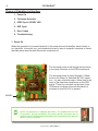
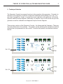
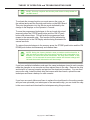
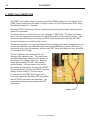
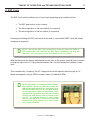
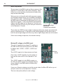
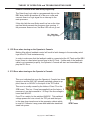
Patriarch Generator Theory of Operation and Troubleshooting Guide Overview: The Patriarch high frequency x-ray generators are built around an embeded software, unique hardware configuration designed to provide accuracy and economy in a small package. Power requirements are 240 VAC Single Phase and Three Phase depending upon the kW selected. All of the generators share the same architecture as far as circuit boards, electrolytic storage capacitors, high voltage transformers, IPMs (Intelligent Power Modules) and other electronic components. All of the generators come complete with the GTR APR Console (both veterinary and human). The basic operation of the generator is as follows: • The incoming power line is rectified and stored in the DC Buss during the PREP cycle • Techniques are selected on the Operator’s Console • When the EXP pushbutton is pressed pulse-width modulated drive is sent to the control circuits of the IPMs and produce a chopped 40 kHz input to the high voltage transformer • The output of the transformer is monitored by control circuitry in the high voltage tank and is fed back to the pulse-width modulating control to set and maintain the technique factors selected by the operator • The output of the transformer is also fed to the x-ray tube to provide rotor, filament current and high voltage control • All dynamic factors are constantly monitored by the embedded software system to maintain control of the exposure factors and safe operation in case of a fault. Copyright 2011 GTR LABS, Inc. PATRIARCH ® 2 Theory of Operation by function: 1. Power On 2. Technique Selection 3. PREP Cycle / READY LED 4. EXP Cycle 5. Error Codes 6. Troubleshooting 1. Power On When the generator is connected properly to the power line and all ancillary items (bucky, rotor, interlocks, foot switch, etc.) are connected correctly, there is a specific sequence of events that take place when the wall disconnect is switched on. The incoming power is fed through the line fuses to the input connector on the SPB circuit board. The incoming power is routed through 2 15Amp fuses to the relays for Switched 240 VAC operation. It is also routed through a .3Amp fuse to the input of the step-down transformer on the SPB board. There is a neon bulb on the input to the SPB board to indicate if the wall disconnect is switched on and 240 VAC is present. 240VAC NOTE: The generator is shipped with DIP1-1 on the BBU board in the off position. During installation this switch will be moved to the on position and all the information detailed here is assumed to be with the switch in the on position. Copyright 2011 GTR LABS, Inc. THEORY OF OPERATION and TROUBLESHOOTING GUIDE 3 During initial power on using the wall disconnect switch a set of hardware and software checks are performed by the BBU circuit board. These will help you in trouble shooting a fault and are explained here in detail. Immediately upon turning on the wall disconnect the step-down transformer on the SPB board supplies 38 VAC to the main rectifier on the board to supply basic DC power for the generator. This DC power is then fed to 4 regulators for the specific requirements of the generator. They are +5VDC, DIP1 +12 VDC, +12 VDC and -12 VDC. The +5VDC supply is routed through the ribbon cable directly to the BBU Watch Dog LED to power the processor. The -12VDC supply is routed through the ribbon cable to the BBU and then on to Test Points the TEC circuit board to supply one rail of the RMS convertor which is used to measure Filament Current. One of the +12VDC supplies is used for relay power and general distribution and the other +12VDC supply is specifically for the Operator’s Console. All of these supplies have test points on the BBU board and should be within +/- 5% of their stated value. During the first 2 to 3 seconds of power being applied by turning on the wall disconnect the processor on the BBU board begins to run at 20 MHz and performs the following steps. • Turns on the Blue LED on the BBU board • Checks all interlocks • Establishes communication with the processor in the Operator’s Console • Sets the frequency and dead time for the pulse width modulator control • Turns off the Blue LED on the BBU board At the end of 2 to 3 seconds the Blue LED will go out (extinguish) indicating a successful initializing of the embedded software system and hardware check. The Operator’s Console may now be turned on successfully. Copyright 2011 GTR LABS, Inc. 4 PATRIARCH ® Pressing the On/Off pushbutton on the Operator’s Console causes the following to happen: • The audible tone used to indicate X-Ray on is tested for several seconds. • All LEDs on the Operator’s Console including the segments in each of the display modules are turned on so their proper function can be seen. • At the end of this sequence the BBU board in the generator sends technique factors to the processor in the Operator’s Console telling it what to display. • On an initial power up after the wall disconnect has been turn off and back on this will be the default information. • When only the Operator’s Console is cycled off and back on the last technique displayed on the console will be restored. At the end of a successful ON cycle for the Operator’s Console several things happen: • The two 240VAC switched relays on the SPB board energize providing power to the TEC board, the rotor circuit and the cooling fan mounted on the IPM Thermal Module. • At the end of 7 seconds the processor on the BBU board checks the input from the RMS convertor on the TEC board for the proper level of Standby Filament Current. If this current is missing or incorrect an E07 Error Code will be displayed on the Operator’s Console. Otherwise, a successful Power On sequence will have occurred and the generator is ready to respond to Operator Commands. Copyright 2011 GTR LABS, Inc. THEORY OF OPERATION and TROUBLESHOOTING GUIDE 5 2. Technique Selection The Operator’s Console has several functions in the operation of the generator. Primarily it is the input for the Operator in selection of exposure technique and the taking of an x-ray. If is also used, through Error Codes, to monitor the correct operation of the generator for both the Operator and the Service Engineer. And finally, it is used as a tool for the correct set up of the generator as well as calibration and diagnostics by the Service Engineer. There are two versions of the Operator’s Console – the Human and the Veterinary. There are two basic differences in the consoles. The graphic overlay indicating the intended use and the software that is programmed into the console. Function and operation are identical between the two. Prep On / Off Exp Prep On / Off Exp Copyright 2011 GTR LABS, Inc. PATRIARCH ® 6 The Operator’s Console has two modes of operation – manual and APR (Anatomically Programmable). In the Manual mode the Operator must enter techniques (kVp, mA, Time and / or mAs) manually from a chart or a pre-determined list that is applicable to the imaging system used (ie. Film/screen, DR Imaging, CR Imaging, etc.). Any ancillary equipment such as Bucky or AEC inputs must be selected manually as well. in the APR mode there is an array of 12 selectable body parts on the left of the Operator’s Console. Each selection pushbutton can be toggled between two states – AP and Lateral to allow different technique storage for each view. In addition there is a CM display to indicate the Centimeter thickness of the patient’s anatomy. This may be increased or decreased as necessary and adjustments are made in the displayed technique accordingly. Pressing one of the push buttons for an APR technique switches the console to APR mode. Pressing one of the push buttons for the kVp, mA, Time, mAs or any other function on the right side of the console (except PREP and EXP) switches the console to manual mode. The pre-programmed techniques loaded from the factory are for a 400 speed film/screen system. These techniques have proven over time to be approximately correct for this type of imaging system. In the case of digital imaging (DR or CR) some experimenting will be required to determine the correct technique level due to the differences in imaging speed between the modalities. Because the techniques are stored in Flash Memory in the Operator’s Console the techniques can be changed by the Operator or the Service Engineer at any time. There are some basic facts to know about the system if you are going to make changes. a) You can restore factory default techniques at any time by pressing simultaneously the STORE push button and the AEC RESET push button and releasing them. NOTE: Any activity initiated to store, change and/or restore techniques will be indicated using the decimal point in the CM Display window. If this decimal point illuminates for several seconds after you have initiated a change, that change has been executed successfully. If the decimal point does not illuminate you have not been successful in your attempt to change the stored technique. b) You can change techniques individually by body part, view and CM thickness c) You can change techniques globally up or down by individual body part or by all stored techniques d) Once you have altered the techniques to satisfy your requirements you can store them in an additional on-board flash memory chip. This chip can then be used to transfer the techniques to another console. Copyright 2011 GTR LABS, Inc. THEORY OF OPERATION and TROUBLESHOOTING GUIDE 7 a) Technique reset to factory default As indicated, factory techniques supplied with the Operator’s Console (both the Human and Veterinary consoles) are for a 400 speed film/screen system. If you make changes in the stored technique using any of the methods available you can always return to the factory default by simultaneously pressing the STORE push button and the AEC RESET pushbutton and releasing them. These techniques are hard coded into the processor as part of the operating system and will always be available regardless of any changes made. b) Changing techniques individually by body part, view and CM thickness To change an individual technique for a body part, view or CM thickness the procedure is very simple. Press the push buttons associated with the body part, view and CM thickness you are changing. Press and hold the STORE push button. Manually select the new technique factors (kVp, mA, Time and mAs). Release the STORE push button and observe the decimal point in the CM display window. If it illuminates for several seconds you were successful in storing the new technique. NOTE: To determine if the technique you are using is a factory default technique or one you have altered, simply look at the CM display when you select a body part. If the decimal point is illuminated (without any push button input) the technique displayed is a factory default technique. If the decimal point is not illuminated you are viewing a technique that was altered using the STORE pushbutton. Using this technique you can change any or all stored techniques one by one. This allows you to minutely adjust techniques without changing all the techniques in the case of a specific body part of view or thickness. c) Changing techniques globally up or down by individual body part or all stored techniques. The following procedures apply to changing globally a section or all of the stored techniques. Built in to the operating system for the APR Operator’s Console is the ability to alter a family of techniques or all the stored techniques with the pressing of two push buttons simultaneously. The procedure is the same for either procedure but the start point is different. Copyright 2011 GTR LABS, Inc. 8 PATRIARCH ® If you are change only a particular body part globally, first select that body part and have a value displayed in the CM display window. This will cause only those techniques associated with the selected body part to be changed. If you are changing all of the stored techniques simultaneously make sure that there is nothing displayed in the CM display window. It doesn’t matter what manual technique is showing, just make sure the CM display window is empty (not illuminated). In the following procedure each step up or down will make a change of 30% optical density in the image. You will not be changing the technique by 30% up or down. You will be changing the optical density of the image by 30% up or down. This can be confusing. Technique selection and optical density are not linear changes. A small change in the technique (kVp up or down several kVp) can make a significant change in the image. With the correct selection of the technique to be changed (individual technique with CM window illuminated – or all techniques with the CM window not illuminated) press simultaneously and release the STORE push button and the AEC UP or AEC DOWN push buttons. The decimal point in the CM window will be illuminated for several seconds to indicate a successful change. If you use the AEC UP push button you will increase the stored technique by 30% optical density. This will have the effect of adjusting your system for use with a slower film/ speed rating. As an example - if you perform this step 3 times in a row you will have changed your film/speed from the equivalent of a 400 speed system (factory default) to a 200 speed system. You will have doubled your optical density. If you use the AEC DOWN push button you will decrease the stored technique by 30% optical density. This will have the effect of adjusting your system for use with a faster film/speed rating. As an example – if you perform this step 3 times in a row you will have changed your film/speed from the equivalent of a 400 speed system (factory default) to an 800 speed system. You will have halved your optical density. Note: All technique factors for successfully imaging in a specific location are subject to the individual characteristics of that particular installation. Factors such as age and condition of cassettes and screens, the temperature and speed of the film processor, the actual speed of the CR or DR system, the age of the x-ray tube, calibration of the x-ray generator all can have a direct effect on the final image. d) Storing and Retrieving APR programming Upon completion of any changes to the technique programming, you should save he changes to the on-board flash removable chip included for that purpose. Copyright 2011 GTR LABS, Inc. THEORY OF OPERATION and TROUBLESHOOTING GUIDE 9 NOTE: This step requires the Service push button to be pressed on the BBU board. To activate the storage function you must remove the cover on the cabinet and press the Service push button on the BBU Board. This puts the generator into the Service mode indicated by the change in the displays on the Operator’s Console. To save the programmed techniques to the on-board chip simultaneously press the STORE push button and the CM UP push button and release them. This will write the programmed techniques to the removable chip. This function will be indicated by the decimal point in the CM Display window being illuminated for several seconds. To restore these techniques to the memory press the STORE push button and the CM DOWN push button simultaneously and release them. NOTE: Using the factory default reset procedure outlined earlier in this text does not affect the information stored in the removable chip, however to retain the saved information the chip must remain in the socket. If it is removed for more than 2 weeks the internal charge will fail and the stored information will be corrupt. If you have multiple installations and want the same techniques stored in each console, make the changes in one console and then upload them to the chip. Remove the chip and install it in a second console and perform the download procedure. You can then remove the chip, install the blank chip that comes with the console, upload the new techniques and have a backup for each console. If you have a console failure and have to replace the circuit board or the entire console and you have uploaded your techniques to the removable chip, you can install the chip in the new console and download the techniques using this procedure. Copyright 2011 GTR LABS, Inc. PATRIARCH ® 10 3. PREP Cycle / READY LED The PREP Cycle begins when you press and hold the PREP push button. The length of the PREP Cycle is based upon the value of Setup Location #23 (Low Speed Rotor Boost Time). The Factory Default is 1.7 seconds. During the PREP Cycle the processor is performing several operations and checking critical areas of the generator. The first operation is to boost the rotor from stationary to 3600 RPM. The Main and Phase legs of the rotor windings are monitored on the SPB board by current sensing circuits. If the current through either leg is zero during the PREP Cycle the generator will stop the PREP Cycle and display an error E04 on the console. The second operation is to boost the filament current and thus the filament temperature to the correct value based on the calibration data stored in the RAM Memory during calibration. If the value is low or high the generator will stop the PREP Cycle and display an error code E08 for low and an E10 for high. The third operation is to check the DC Volt charge on the capacitor buss. This check does not read the absolute voltage but just checks for the presence of voltage on the buss. Anything above approximately 200 VDC will indicate a positive charge. If the processor does not detect voltage on the buss by the end of the PREP Cycle the generator will stop the PREP Cycle and display an error code E17 on the console. If, at the end of the PREP Cycle there are no error codes detected, the Green LED associated with the PREP push button will illuminate. You may initiate an exposure by pressing the EXP push button. Charge LED Copyright 2011 GTR LABS, Inc. THEORY OF OPERATION and TROUBLESHOOTING GUIDE 11 4. EXP Cycle The EXP Cycle can be initiated one of three ways depending upon installed options. • The EXP push button on the console • The second position of the hand switch (if connected) • The second position of the foot switch (if connected) Pressing and holding the EXP push button at the end of a successful PREP Cycle will initiate an exposure sequence. NOTE: During the EXP Cycle momentarily releasing either the PREP or EXP push buttons will terminate the EXP Cycle immediately and stop the exposure. The same goes for the hand switch or the foot switch. With the filament at the proper temperature and the rotor at the proper speed all that is needed to begin an exposure is +/- kVp potential between the x-ray tube anode and cathode connections. This is achieved by “chopping” the DC Voltage stored in the capacitor buss through an “H” Bridge arrangement using 4 IGBTs housed 2 each in 2 individual IPMs. NOTE: IPM stands for Intelligent Power Module. The modules used in the generator contain two IGBTs (Insulated Gate Bi-Polar Transistor) each. The IPM module differs from the IGBT module in that the IPM module has additional, highspeed circuitry to monitor both the current level through the IGBT and the rate of change of that current. The internal circuitry is much faster than an external circuit and prevents the IPM module from failing because of a short circuit, over current condition. Copyright 2011 GTR LABS, Inc. PATRIARCH ® 12 The generator uses Pulse Width Modulation to control the input power of the HV Transformer to develop and maintain the proper output. This Pulse Width Modulation allows for the precise adjustment of tube current and kVp during the EXP Cycle. Power line deviations of up to +/10% can be compensated for automatically using Pulse Width Modulation. There is a sophisticated feedback system employed to monitor output kVp and tube current during the entire EXP Cycle. If the processor detects any deviation outside of programmed levels of the kVp or tube current the EXP Cycle will be stopped immediately and the appropriate error code displayed on the console. If the internal current monitoring circuitry of the IPM detects a fault the error code E14 will be displayed. There are a series of cross-checking “dead man” timers monitoring the length of the exposure. The selected exposure time is the maximum length of the exposure. It is not possible to have an exposure last longer than the selected exposure time. At the end of the exposure time the Pulse Width Modulation will cease and the kVp and tube current will return to zero. You must release the EXP push button to initiate another EXP Cycle. 5. Error Codes There is a detailed chart in the Technical Manual listing all the possible Error Codes that can be displayed and giving an explanation and suggested corrective action for each code. The generator uses the error code system two ways. First and foremost it protects itself from a catastrophic failure of key generator components or other components in the high voltage circuit (ie. HV Cables and/or X-Ray Tube). Secondly the error code system is used to communicate with the operator or the service technician the nature of the fault that has occurred. In the case of the operator, this information can be used to communicate with the service organization the area of the generator most likely to need service. In the case of the service engineer, this information can be used on-site to troubleshoot the problem. Copyright 2011 GTR LABS, Inc. THEORY OF OPERATION and TROUBLESHOOTING GUIDE 13 6. Troubleshooting Successfully troubleshooting the generator requires several things: • A comprehensive understanding of the information contained in this Theory of Operation. • Knowledge of the possible Error Codes that can be displayed and their causes • Proper test equipment All of the Error Codes and their possible causes are detailed in the chart in Chapter 7 of the Service Manual. In this section of the Theory of Operation you can find specific steps to follow to successfully troubleshoot the most common faults or Error Codes. 1. Cannot turn on the Operator’s Console 2. E01 Error when turning on the Operator’s Console 3. E13 Error when turning on the Operator’s Console 4. E07 Error 7 seconds after turning on the Operator’s Console 5. E08 or E10 Error when pressing the PREP pushbutton 6. E17 Error at the end of the PREP Cycle 7. E03 Error when pressing the EXP pushbutton (if bucky selected) 8. E14 Error when pressing the EXP pushbutton 1. Cannot turn on the Operator’s Console This error can show up in several ways. • Operator’s Console locks up during an exposure and will not turn off or allow a displayed technique to be changed. When you turn off the wall switch and turn it back on to clear the console, it will not come on. • Operator’s Console will not turn on • Blue LED on BBU board will not go out when the wall switch is turned on There are 3 main causes of this error: • Loss of function in one or both of the RS232 communication chips • Missing DC voltage on the BBU • Loss of function in the Gate Array Logic chip on the BBU (7060) Copyright 2011 GTR LABS, Inc. PATRIARCH ® 14 RS232 chip failure: The processor in the BBU board and the processor in the Operator’s Console talk to each other constantly. Even if there is no user input they continuously tell each other they are there and ready. When you turn on the wall switch both processors power up and begin running and go out to establish communications with each other. Until that happens, the blue LED on the BBU board is illuminated and you cannot turn on the Operator’s Console. If one of the RS232 communication chips on the BBU board or the Operator’s Console is not working, the blue LED will not go out and you cannot turn on the Operator’s Console. RS-232 Comm Chips BBU U-15 Console U-6 (not shown) These chips are CMOS and are subject to damage with power surges associated with arcing or excessive noise. A big spike on the incoming power line can knock one or both out and a high voltage arc in the x-ray tube or high voltage cable can do the same. If this occurs during an exposure, the console locks up. Missing DC voltage on the BBU board: There are 4 regulated low voltage DC supplies on the SPB circuit board and they are fed to the BBU by ribbon cable. +5VDC, +12VDC, +12VDC and -12VDC. The +5VDC supply is for the processor and logic. Test Points One of the +12VDC supplies is for the system relays and the other one is for the Operator’s Console. The -12VDC supply is for the RMS convertor on the TEC pcb which converts the chopped filament current signal to true RMS which is monitored by the processor. If any one of these is missing or not at the correct value, the Blue LED will not go out and you cannot turn on the Operator’s Console. There are test points (white) for each voltage. Copyright 2011 GTR LABS, Inc. THEORY OF OPERATION and TROUBLESHOOTING GUIDE 15 Loss of Function in the Gate Array Logic chip: The Gate Array Logic chip is a programmed chip on the BBU board which processes all of the error codes and converts them to a logic signal for an interrupt to the main processor. If this chip fails the most likely result is a low on the interrupt line which prevents the processor from running. If the processor does not run, the Blue LED will not go out. U6 - 7060 Gate Array Logic Chip 2. E01 Error when turning on the Operator’s Console Making kVp without feedback control will result in fatal damage to the secondary windings in the HV Tank instantaneously. In order to make sure that the feedback cable is connected at the HV Tank and the BBU board, there is a hard wired ground loop in the HV Tank. If either end of the feedback cable is not connected properly, the Operator’s Console will start and immediately display the E01 Error. 3. E13 Error when turning on the Operator’s Console This error indicates that once the Operator’s Console has been turned on and the 240 VAC internally switched voltage is applied, there is no 240VAC to the input of the TEC board. This error is usually caused by the failure of Fuse F3 on the SPB board. This is a 1 Amp fuse supplied from the factory. If necessary it can be increased to 1.5 Amp if the line voltage is lower than 240VAC. Fuse F3 is a safety for the switched 240VAC. This switched voltage powers the rotor circuit, the TEC pcb and the input to the step down transformer in the generator cabinet which is used for Collimator Lamp power and table/tube stand/wall stand lock power. Copyright 2011 GTR LABS, Inc. SPB Fuses 16 PATRIARCH ® Any failure of an electromagnetic lock or short in any leg of the rotor cable or failure of a critical component on the TEC pcb will cause Fuse F3 to blow. If you replace the fuse and it blows immediately, begin taking loose circuits (disconnect the rotor cable, disconnect the 240VAC input to the step down transformer) until you determine the cause of the error. 4. E07 Error 7 seconds after turning on the Operator’s Console The main processor on the BBU board constantly monitors the current flowing through the x-ray tube filament. When the Operator’s Console is first switched on there is a 7 second delay before the processor begins monitoring. This allows the pre-heat voltage to be applied to the filament and for the filament current to stabilize. At the end of 7 seconds the monitoring begins and if the current is zero the Error 07 is displayed. You can monitor the Filament Current on the BBU board at test point FILI. In standby mode the DC voltage measured on the test point should be approximately 1.9 VDC. When the PREP pushbutton is pressed the voltage will rise to the value which represents the data stored during calibration for that mA station. This error can indicate the failure of a filament in the x-ray tube or a failure on the TEC pcb. A quick check when this error occurs is to turn off the Operator’s Console, turn it back on and quickly change filaments. If the error does not return that filament is working. Switch back to the other filament and if the error returns that filament is open. The open circuit could be in the HV Tank, the cathode hv cable or the x-ray tube. Further measuring will determine the source of the error. If the error occurs on both filaments, the most likely cause is a defective TEC pcb. There are two Green LEDs at the extreme bottom of the TEC pcb. During normal operation of the components on the TEC pcb both of these Green LEDs should be illuminated equally bright. If one of them is not illuminated or is dim compared to the other one, replace the TEC pcb. This error can also be cause by a failure of the Gate Array Logic chip. 5. E08 or E10 Error when pressing the PREP pushbutton During an EXP sequence, the main processor on the BBU board monitors the mA in the feedback loop from the HV Tank. It compares the value it is reading with the value selected on the Operator’s Console. If this value varies more than the allowed tolerance the EXP sequence is stopped and the error is displayed. Copyright 2011 GTR LABS, Inc. THEORY OF OPERATION and TROUBLESHOOTING GUIDE 17 E08 says the value monitored is too low. E10 says the value monitored is too high. Either error indicates that the generator needs a complete calibration. An intermittent E08 or E10 error could indicate a failure of the Gate Array Logic chip on the BBU pcb. 6. E17 Error at the end of the PREP Cycle To make high voltage, the generator stores energy in the form of DC voltage in the capacitor bank attached to the main DC Buss. When the EXP pushbutton is pressed this DC voltage is chopped up at 40 kHz and fed into the primary of the HV Tank. The electrolytic capacitors used in the DC Buss have a very large storage capacity and, if connected directly to the power line through the main contactor while they are completely empty, would draw enough current to blow the main fuses in the generator and the 100 Amp circuit breaker in the wall switch. This would weld the contacts shut on the contactor and create a dangerous situation. To make sure that does not happen, the generator has a “soft charge” circuit consisting of a secondary contactor and a 10 ohm, 100 Watt wire wound resistor in series with one of the AC inputs to the DC Bridge Rectifier. This circuit provides control of the sudden inrush current associated with the charging of a large electrolytic capacitor. This circuit is bypassed when the main contactor successfully closes. The “soft charge” is occurring during the PREP cycle. This time is programmable in the software setup. The factory default is 1.7 seconds. Near the end of the PREP cycle the processor looks at the DC voltage level on the Buss through circuitry on the SPB board. This circuit does not read absolute voltage but a minimum allowable level required before the main contactor can close. If the voltage is not present, the error E17 is displayed and the main contactor does not close. There are several specific reasons for this error: • An open 10 ohm 100 Watt “soft charge” resistor. • An open voltage divider resistor on the SPB board in the sensing circuit. • A defective “soft charge” relay on the SPB board. There is one other situation involving the E17error. It is very rare but is a possibility when troubleshooting the E17 error. When the generator is switched off or after 20 seconds has passed since the last PREP pushbutton input, a DC Buss discharge circuit is energized. This circuit consists of a relay on the SPB board and a 50 ohm 100 Watt resistor. Copyright 2011 GTR LABS, Inc. 18 PATRIARCH ® Should a situation occur where the relay contacts on the discharge relay are welded together, you can have a situation in which the charge relay is closed and current is flowing through the “soft charge” circuit and the same current is also flowing through the discharge relay and the discharge resistor. If this occurs you can immediately tell the problem by the excessive heat given off by the discharge resistor. This situation may or may not cause the error E17 to be displayed. It is dependent on the number of capacitors in the Buss array, the line voltage level and the voltage divider resistors on the SPB board. In any case, if this occurs replace the SPB board and both the “soft charge” and discharge resistors. 7. E03 Error when pressing the EXP pushbutton (if bucky selected) If you have either or both buckys enabled and you select Bucky1 or Bucky2 on the Operator’s Console the following sequence of events occur: • At the end of the PREP Cycle you press the EXP pushbutton • Instead of initiating an exposure, the EXP pushbutton directs the main processor to energize the Bucky1 or Bucky2 relay on the SPB board. • The relay contacts close allowing the bucky motor to run which closes the Bucky Motion switch providing a low level to the Bucky Motion input of the SPB board. • This input is processed through an opto-coupler and input to the main processor which begins the exposure. If, upon pressing the EXP pushbutton, this sequence does not occur as described, you will get an E03 error in 5 seconds. This error tells you that either you did not get voltage to the bucky motor, or the motor did not respond, or the motion switch did not engage and put a signal low on the SPB board input. 8. E14 Error when pressing the EXP pushbutton When you press the EXP pushbutton on the Operator’s Console, a pulse width modulated drive signal is fed to the bases of the 4 IGBT transistors in the two IPM modules attached to the DC Buss. The energy stored in the DC Buss is then chopped at 40 kHz and applied to the input of the HV Tank at P1/P2 causing current to flow in the primary windings of the HV Transformer. The error E14 indicates a failure in this process. Each IPM has 2 IGBT transistors built in with high-speed detection circuitry to monitor the current passing through each IGBT. Copyright 2011 GTR LABS, Inc. THEORY OF OPERATION and TROUBLESHOOTING GUIDE 19 If a current that is too high for the IGBT or a sudden rise in current beyond the maximum programmed value, the detection circuitry stops the drive to the IGBT, shuts down the exposure and outputs a fault signal. The fault signal is sensed by the main processor on the BBU board and the error E14 is displayed. The detection circuitry can be triggered by several causes: • A short in one of the IPMs • A failure in the high voltage side of the x-ray generator • A weak power line A shorted IPM: If the error E14 is occurs, you must recycle the Operator’s Console on/off to clear the error. To determine if the error is caused by a shorted IPM simply select the lowest technique factors available on the Operator’s Console (40 kVp, 25 mA, .001 sec.) and attempt to make an exposure. If the error E14 appears the most likely cause is a short in one of the IGBT in one of the IPM modules. Using an auto-ranging ohm meter, test the three terminals on each IPM. Be sure and check each combination (1-3,1-2,2-3). The readings should be either infinity or a counting up or down indicating the charge or discharge of the capacitor bank. If any combination of terminals indicates the same resistance in both directions when reversing your meter leads (ie. 3.5 ohms) that IPM has a shorted IGBT in it and must be replaced. When the minimum technique exposure produces an error E14, the most likely cause is a shorted IPM. High Voltage Failure: A failure in the high voltage side of the generator produces an arc to ground or between anode and cathode in the High Voltage Tank. This arc causes the current through the IPM to increase dramatically, thus tripping the detection circuitry. This is a good thing in that it protects the high voltage components from catastrophic failure normally associated with an arc. However, it is difficult to pin point the exact cause of the arc. If the generator passes the minimum technique factor exposure test in the previous cause (a shorted IPM), conduct this test to determine if the error E14 is caused by an arc or a weak power line. Select 25 mA, 80 kVp and .1 milliseconds time. Make an exposure. If the error does not appear increase the kVp by 10 and make another exposure. Continue until you have reached 120 kVp or the error has occurred. A high voltage arc caused by a failing x-ray tube or a defective high voltage cab le or a component failure in the High Voltage Tank will present itself at high kVp Copyright 2011 GTR LABS, Inc. PATRIARCH ® 20 levels regardless of the mA station selected. That’s why you use 25 mA for this test. If the error E14 appears during this test, you have an arc somewhere in the x-ray tube, hv cables or hv tank. A weak power line: High Frequency X-Ray Generators have a peculiar characteristic which requires that they be connected to a very strong power line. When the exposure begins the energy stored in the capacitor bank (DC Buss) is used to begin the exposure. As the exposure progresses, this energy drops and must be replenished from the power line. Unfortunately, because of the unique nature of the generator’s power requirements, this line current does not take the form of a normal sine wave current. It is trapezoidal in shape and has long zero levels followed by very high, sharp sided peaks. The incoming AC line is rectified and stored in the capacitors through a single phase or 3 phase bridge rectifier, based on the generator configuration. This bridge can only conduct forward current when the voltage value representing the stored energy in the capacitors is less than the energy available on the line side of the bridge rectifier. In other words, the bridge rectifier is reverse biased during most of the incoming line sine wave. The exposure is rapidly dumping the stored energy in the DC Buss into the HV Tank primary windings. As the sine wave increases in the incoming line it reaches a point where the diodes in the bridge rectifier begin to conduct and replenish the energy in the capacitors. This causes a very large current draw on the incoming line. For instance: assume the following technique factors – 300 mA, 100 kVp, 100 milliseconds – 30 kW. If your generator has a 240 VAC input line voltage the instantaneous line current will be 125 Amps. If you have a 208 VAC input this current will be 145 Amps. Unless you have a mains supply transformer whose KVA rating is larger than the kW rating of your generator, you are going to exceed the capability of your transformer. This will cause a sudden line voltage drop and an increase in the current through the IPMs. This current increase will trigger the error E14. It is very difficult to get electricians and contractors to understand this phenomenon. That is why you must have a large, dedicated mains transformer and the largest, stranded copper wire the local electrical code will allow feeding the wall disconnect. And, in the case of buildings sharing a mains transformer, or one mains transformer feeding the clinic, you must calculate the total load on the transformer including heat pumps, sterilizers, lighting, air conditioning, etc. It’s no good having a 40 KVA mains transformer but only having 20 KVA available for the 30 kW x-ray generator. Copyright 2011 GTR LABS, Inc.