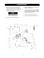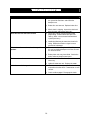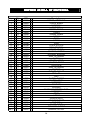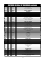
1
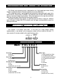
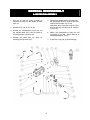
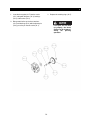
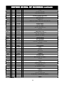
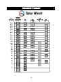
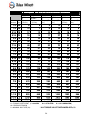
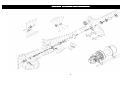
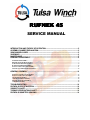
DESIGN SERIES 002
RUFNEK 45
SERVICE MANUAL
INTRODUCTION AND THEORY OF OPERATION ............................................................................2
ASSEMBLY NUMBER EXPLANATION..............................................................................................2
WINCH MODEL CODES ......................................................................................................................2
!WARNING!...........................................................................................................................................3
MAINTENANCE ....................................................................................................................................5
GENERAL DISASSEMBLY..................................................................................................................6
A. MOTOR DISASSEMBLY ....................................................................................................................................................... 7
B. BRAKE SECTION DISASSEMBLY....................................................................................................................................... 7
C. DRUM SECTION DISASSEMBLY ........................................................................................................................................ 8
D. GEAR SECTION DISASSEMBLY.......................................................................................................................................10
E. INPUT PLANET SET DISASSEMBLY ................................................................................................................................11
F. OUTPUT PLANET SET DISASSEMBLY ............................................................................................................................12
GENERAL ASSEMBLY......................................................................................................................13
G. OUTPUT PLANET SET ASSEMBLY..................................................................................................................................13
H. INPUT PLANET SET ASSEMBLY.......................................................................................................................................14
I. GEAR END ASSEMBLY........................................................................................................................................................14
J. DRUM SECTION ASSEMBLY .............................................................................................................................................14
K. BRAKE SECTION ASSEMBLY ...........................................................................................................................................14
L. MOTOR ASSEMBLY ............................................................................................................................................................14
TROUBLESHOOTING........................................................................................................................14
RUFNEK 45 BILL OF MATERIAL .....................................................................................................14
VISCOSITY CHART............................................................................................................................14
TORQUE SPECIFICATIONS CHART................................................................................................14
RUFNEK 45 ISOMETRIC DRAWING ................................................................................................14
INTRODUCTION AND THEORY OF OPERATION
The Rufnek series planetary winch is designed to use a high-speed gear motor, driving
through a multiple disc brake, through two planet sets to the cable drum.
The multiple disc brake is spring applied and hydraulically released through a port in the
brake housing. During inhaul, the brake is not released since the load is driven through the
one-way cam clutch, bypassing the brake. When the load comes to a stop, the cam clutch
locks up and the load is prevented from moving by the brake.
The brake and brake valve receives its signal any time the winch is in pay out. With the
brake fully open at about 340 PSI the brake valve will open and dynamically control the
lowering of the load.
ASSEMBLY NUMBER EXPLANATION
This manual is for design series 002. In the case of a major design change
implementation, a new design series designation number will be issued for the winch. A
new manual will also be created for that specific design series.
ASSEMBLY #
DESIGN
SERIES
81865 002
WINCH MODEL CODES
RN45
P H L X O A 1
Motor Type
1. Single Speed Gear Motor
2. Two Speed Gear Motor
3. Single Speed Geroler Motor
4. Two Speed Geroler Motor
5. Piston
6. Vane
X. No Motor
Gear Type
W=Worm
P=Planetary
Drive Type
H=Hydraulic
M=Mechanical
Gearbox Position
L=Left
R=Right
(viewed from rear of truck)
Input Shaft Location
F=Front
R=Rear
X=Does not apply
(viewed from rear of truck)
Clutch Device
M=Mechanical
A=Air
Cable Spooling
O=Over Drum
U=Under Drum
(viewed from rear of truck)
2
!WA
!WA
RN
RN
IN
G
!WA
!WA
RN
RNIN
IN
ING
G
G!!!!
FAILURE TO HEED THE FOLLOWING WARNINGS
MAY RESULT IN SERIOUS INJURY OR DEATH.
The safety of the winch operator and ground personnel should always be of great concern,
and all necessary precautions to insure their safety must be taken. The primary mover and
the winch must be operated with care and concern for the equipment and the environment
and with a thorough knowledge of the equipment and its performance capabilities must be
understood. These general safety guidelines are offered, however local rules and
regulations or national standards may also apply. Recommended references are, but not
limited to, ANSI B30, OSHA 1910, AWS D 14.3, and SAE J706.
Additional information can be found at http://www.team-twg.com/TulsaWinch/
Indicates an imminently hazardous situation which, if
not avoided, will result in death or serious injury.
Indicates a potentially hazardous situation which, if
not avoided, could result in death or serious injury.
Indicates a potentially hazardous situation which,
if not avoided, may result in minor or moderate injury
or property damage.
Indicates information or a company policy that
relates directly or indirectly to the safety of
personnel or protection of property.
Mounting:
Winch mounting must be secure and able to withstand the applied loads.
•
•
•
•
The stability of the mounting system must be approved by a qualified person.
All welding should also be done by a qualified person.
Winch mount must be flat so as not to induce binding.
The flatness must not exceed 1/16 inch across the mounting surface of the winch
itself.
Guards must be placed on all open drives in the case of mechanical winches. Insure that
all hydraulic hoses, valves and fittings are rated to winch manufacturer’s operating
pressures.
Relief valves should be set to winch manufacturer’s specifications. Insure that all PTO’s
and drivelines are sized appropriately for the winch manufactures speed and torque
specifications.
3
Operator:
Must read and understand the operating and service manual.
Both the SERVICE MANUAL and OPERATING AND MAINTENANCE MANUAL
are available online at http://www.team-twg.com/TulsaWinch/
Must never lift or move people with this winch.
This winch is not designed or intended for any use that involves moving people.
Must stay clear of the load at all times.
Ground personnel should remain a safe distance from the load and winch cable at
least 1 ½ times the length of cable measured from the winch to the load.
Must stay clear of the cable at all times.
A broken cable can cause serious injury or death.
Must avoid shock loads.
Shock loads can impose a strain on the winch that can be many times the design
rating.
Must be aware of the fleet angle of the winch.
All loads should only be pulled with the load line perpendicular to the drum shaft, this
is to avoid excessive stresses on the winch and will help prevent the cable from
building on one side of the drum flange.
Must wear personnel protective equipment (PPE) if required.
Check the local, state and federal regulations for compliance.
Must insure that the drum clutch is fully engaged before hoisting.
A visual inspection of the drum clutch engagement is required before each winching
operation.
Must rig all loads secure before winching.
Pull the load line taut and inspect the condition of load for stability.
Must inspect the drum brake if equipped.
The drum brake is not a load holding device it is design to prevent over spooling of
the drum and causing bird nesting of the cable on the drum. Inspect the brake for
wear of the lining and the actuation method.
Must inspect the load control brake.
These winches are equipped with two (2) forms of dynamic braking. The springapplied/hydraulically-released multi-disc oil brake is one method. Before a load is
handled the load should be pulled tight and stopped to check this brake. The second
method is a hydraulic lowering control. The same method should be used to check
this brake.
Operation:
•
•
•
•
•
All winch controls must be well marked for function to avoid confusion.
All winch controls must be located to provide the operator with a clear view of the
load.
The clutch must be inspected daily for proper operation.
The winch cable should be inspected daily for serviceability.
A minimum of five wraps of tightly wound cable must remain on the drum.
4
MAINTENANCE
Tulsa Rufnek series planetary winches, like any other piece of machinery, need to be
periodically serviced and well maintained to insure proper operation.
Good maintenance consists of four steps.
1. A daily inspection to insure that there are no oil leaks present, all mounting bolts and
other fasteners are tight, and that the wire rope is in good condition.
2. Changing the oil in both the gearbox and the brake section. (Severity of use will
determine the need for oil changes but the oil should be checked at a minimum of every
500 hours. Factors such as extremely dirty conditions or widely varying temperature
changes may dictate even more frequent servicing).
3. Lubing drum bushings and sliding clutch with grease. The drum bushings are lubed thru
two grease zerks located on drum barrel.
4. Complete teardowns and component inspections. (Again, severity and frequency of
use will determine how often this should be done). If the equipment that this winch is
mounted to is subject to standards for this type of inspection, then those standards must
be followed. If oil changes reveal significant metallic particles then a teardown and
inspection must be made to determine the source of wear.
Rufnek series planetary winches are designed with a common oil reservoir for the gearbox
and brake. The winches are shipped from the factory filled with Mobilube SHC SAE 75W90 synthetic gear oil which is satisfactory for operation in ambient temperatures from -40°F
to +110°F. If winch will be operated in temperatures outside this range, contact Tulsa
Winch for recommendations.
The oil is drained by removing the drain plugs (86 & 81) located at bottom of gear housing
(60) & bottom of brake cover (2), then remove the fill plugs (74 & 81) located at the top of
the gear housing (60) & the top of the brake cover (2). Inspect the oil for signs of metallic
particles and/or burning and dispose of in a proper manner. Then re-install the drain plugs.
Fill the brake end with (1 pint) Mobilube SHC SAE 75W-90, then fill the gear end with (7
quarts) of Mobilube SHC SAE 75W-90 oil and replace both of the fill plugs.
OIL CAPACITY = 7 1/2 QUARTS
5
GENERAL DISASSEMBLY
A. MOTOR DISASSEMBLY
1. Drain the oil from the brake assembly by
removing the plug (81) from bottom of brake
cover (2).
5. Remove the counterbalance valve (50) from
the counterbalance block (32) and inspect the
metering hole to make sure it is not
obstructed. Also, inspect the o-rings on valve
to insure that they are not flat or cut. Replace
if necessary.
2. Remove hoses (42, 45, 58, 79, 80).
3. Remove the counterbalance block (32) and
the manifold block (56), from the motor by
removing the four capscrews (48).
6. Motors and counterbalance valves are not
serviceable in the field. Return them to an
authorized dealer for service.
4. Remove the motor from the winch by
removing four capscrews (88).
7. Inspect the o-rings (98) & (49) for damage.
6
B. BRAKE SECTION DISASSEMBLY
should measure no less than 0.055-in. thick
and stator plates should measure no less than
0.068-in thick.
1. Evenly remove the four capscrews (3) that
hold the brake cover (2) in place. Spring
pressure will raise the cover up as the
capscrews are loosened. Carefully remove
the cover (2) from the brake housing (20).
Inspect the o-ring (6) on cover for damage.
6. To disassemble the brake driver/clutch
assembly, remove the retaining ring (17) from
either end of the driver. Then, remove the
brake driver (14) and bearing (52) from the
input driver (19). Next, remove the sprag
clutch (18). Finally, remove the retaining ring
(17) from the other end of the driver, then
remove the second bearing (52) from the input
driver.
2. Remove the springs (7) from the piston (5)
and check the free height. Each spring should
measure at least 1.084 inches with no force on
them.
3. Remove the piston (5) by installing two pieces
of 3/8”-16NC all thread into the two threaded
holes in the piston and run in evenly until the
piston is clear of the housing. An alternate
way of removing the piston is to use shop air
to slowly pressurize the brake port to remove
the piston from the brake housing (20).
Notice the direction of lock-up on
the clutch for re-assembly.
Inspect the input driver and brake driver for
wear, and replace if necessary.
4. Inspect the o-rings (8, 10) and back up rings
(9, 11) on the piston. Grasp the brake
driver/clutch assembly (assembled items 14,
17, 18, 19, 52, 82), and remove it from the
brake housing.
7. Remove the bearing housing (16) and inspect
the needle bearing (15). If necessary, remove
the retaining ring (22) and replace.
5. Remove the stator plates (12) and friction
discs (13) from the brake housing and check
them for excessive wear, and replace if
necessary. Be sure to check the top stator
plate for scoring caused by the removal of the
piston and polish if necessary. Friction discs
8. If the bushing or seal in the brake housing
needs to be replaced, follow the drum section
disassembly and reassembly sections of this
manual prior to reassembly of the brake.
7
C. DRUM SECTION DISASSEMBLY
which frame the mounting bolts are on for reassembly. Inspect and replace if needed.
1. To remove the drum, first disconnect the cable
from the U-bolt (35) and lay aside. If removing
the drum from the motor end with the motor
and brake disassembled, first remove cotter
keys (100) and clevis pins (93) connecting
yoke (87) to bracket (101) & air cylinder (67).
3. Remove the outer thrust collar (105) by
loosening three set screws (89).
4. Remove the yoke (87), sliding clutch (27), and
coupler (30). Remove the two keys (94) from
the shaft (40-9). Remove the drum using a
hoist and inspect the bushings (31) & (4) at
both ends of the drum.
You may need to remove the
airlines, so it’s a good idea to
mark them for re-assembly.
2. Support the weight of the drum with a hoist.
Remove the four capscrews (61) along with
the nuts and washers (62 & 63) on the bottom
of the brake housing (20). Disconnect the
airline running from the air cylinder (68) to the
brake housing (20).
Remove the brake
housing by sliding the housing off the output
shaft (40-9). At this time you will need to
remove two capscrews (70), nuts and washers
(72 & 71) from the frames (64 & 65). Do not
remove air cylinder (68) yet. You can now
remove the brake band assembly (66). Note
You should also inspect the bushing
and seal (38, 25) that are located
in the end of the brake housing.
5. If necessary, replace the drum clutch (28) at
this time by removing six capscrews (33). If
you replace the clutch, make sure to torque
the capscrews to the specified torque upon reassembly. (See torque specifications chart on
page 22 of this manual)
If a complete tear down is not
necessary make sure that the
input shaft (39) does not move
during disassembly.
If the
shaft is allowed to move, the
input spacer (36) will fall into
the gear set ultimately causing
failure to the gear section of
the winch. The gear cover (55)
will have to be removed to
reposition the spacer on the
input shaft.
8
CLUTCH INSPECTION
9
D. GEAR SECTION DISASSEMBLY
3. Inspect the O-ring (59), bearing (23), and
spacer (36).
To remove the output gear set (40),
the drum must first be removed, see
DRUM DISASSEMBLY section on
page 7 of this manual.
4. Remove the input gear set (41), the inner and
outer thrust washers (43), and the sun gear
(44). Inspect and replace if necessary.
1. Drain the oil by removing the plug (86).
5. Remove the output sun gear (47). Carefully
remove the output gear set/output shaft
assembly (40) from the gear housing (60).
2. To disassemble the gear section, remove the
outer cover (55) by removing the eight
capscrews (21).
10
E. INPUT PLANET SET DISASSEMBLY
1. Remove the retaining rings (41-5) from the
planet pins (41-6). Remove the pins from the
carrier (41-1) by carefully tapping them out.
3. With planet gears out, remove the plate (41-7).
4. Inspect the parts for wear or damage and
replace if necessary.
2. Remove the planet gears (41-3), thrust
washers (41-4) and bearings (41-2) from the
carrier (41-1).
11
F. OUTPUT
OUTPUT PLANET SET DISASSEMBLY
1. Remove the retaining rings (40-4) from the
planet pins (40-3).
4. Inspect the parts for wear or damage and
replace if necessary.
2. Remove the pins (40-3) from the carrier (40-1)
by carefully tapping them out.
5. With planet gears out, remove the plate (40-5)
and retaining ring (40-7). Remove the shaft
(40-9) from the carrier (40-1). Inspect the
parts for wear or damage and replace if
necessary.
3. Remove the planet gears (40-2), thrust
washers (40-8), and bearings (40-6) from the
carrier.
12
GENERAL ASSEMBLY
G. OUTPUT PLANET SET ASSEMBLY
1. Insert the output shaft (40-9) into the carrier
(40-1) and install the retaining ring (40-7).
3. Being careful to line up the thrust washers
(40-8) and bearings (40-6) with the planet pins
(40-3), press the pin into the carrier (40-1).
2. Next insert the thrust plate (40-5) into the
carrier (40-1) along with the gears (40-2),
bearings (40-6), and washers (40-8).
4. Replace retaining rings (40-4).
If the pins are not lined
up properly, the thrust
washer can be shattered
during
the
pressing
operation.
13
H. INPUT PLANET SET ASSEMBLY
1. Insert the thrust plate (41-7) into the carrier
(41-1) along with the gears (41-3), bearings
(41-2), and washers (41-4).
3. Replace the retaining rings (41-5).
2. Being careful to line up the thrust washers
(41-4) and bearings (41-2) with the planet pins
(41-6), press the pin into the carrier (41-1).
If the pins are not lined
up properly, the thrust
washer can be shattered
during
the
pressing
operation.
14
I. GEAR END ASSEMBLY
1. Bolt the gear housing (60) loosely into both
frames (64 , 65).
4. Install the inner thrust washer (43) onto the
input gear set (41). Insert the input gear set
(41) into the gear housing making sure it is
against the output gear set (40) and engaged
with the output sun gear (47). Put the outer
thrust washer (43) in place and slide the input
shaft (39) all the way though the output shaft
(40-9). Let the input shaft protrude out on the
gear end so that all of the spline is showing.
Make sure the correct end of input shaft is
towards the gear end.
2. When reassembling, apply grease to parts
such as thrust washers, o-rings, and seals.
Slide the thrust washer (37) onto the output
shaft (40-9). Next, install the output gear set
(40) into the gear housing (60). Push the
gear set into the housing until it stops against
the thrust washer (37).
5. Install the input sun gear (44) and spacer (36)
onto the end of the input shaft (39). Push
back on the input shaft and sun gear at the
same time until the input sun gear engages
the three planet gears on the input gear set.
Put the cover (55) on and secure it with eight
capscrews (21), being careful not to damage
the o-ring (59).
Make sure to line up the gear
teeth in all three planet gears in
the output gear set with the gear
teeth in the housing.
3. Install the output sun gear (47) into the output
gear set (40).
15
J. DRUM SECTION ASSEMBLY
1. After inspecting and replacing the necessary
parts, install the bushing (4) onto the output
shaft (40-9).
drum is supported by both the brake and gear
housings. The air line from the brake band air
cylinder can be attached at this time.
2. Install the drum (34) onto the output shaft.
This part is very heavy and you will need the
assistance of a hoist. With the weight of the
drum supported, install the brake band
assembly (66) and install the capscrews (70),
nut and washers (71 & 72). The brake band
air cylinder (68) can be reattached later.
8. Disengage the sliding clutch (27) so you can
turn the drum freely and tighten all bolts
through the frames to the proper torque
specification (see page 22 this manual).
9. Turn the drum to make sure it is not binding.
10. If necessary, install the cylinder spacer using
four capscrews (29). Next, install the air
cylinder (67) and air cylinder cover (91) to the
brake housing with the four capscrews (69)
and spacers (97).
3. Install the bushing (4) onto the output shaft.
Install the inner thrust collar (24) making sure
the half-moon slots are lined up with the key
slots in the output shaft. (40-9) Tap the two
keys (94) into their slots in the output shaft.
11. Install the bracket (101) to the brake housing
using four capscrews (90).
4. If necessary, install the new drum clutch (28)
using six capscrews (66). Torque to specified
torque (see page 22 this manual). Next, align
the coupler (30) with the keys (94) and slide
onto the output shaft (40-9). Install the sliding
clutch (27) onto the coupler (30).
12. Attach yoke (87) by installing clevis pins (93)
into the bracket (101) and clevis (92). Install
cotter keys (100) to clevis pins (93) to secure
their positions. Connect shop air to the
cylinder and apply air both directions. With the
clutch fully engaged (air applied), there should
be slight movement on the clutch plate in both
directions. Adjust clevis (92) and air cylinder
jam nut accordingly.
5. Install the outer thrust collar (105), aligning the
half moon slots with the keys (94). Tightly
hold the thrust collar against the keys and lock
down the three set screws (89).
6. Slide the brake housing (20) onto the output
shaft (40-9).
7. Bolt the brake housing (20) loosely into both
frames (64, 65) Lower the drum so weight of
16
K. BRAKE SECTION ASSEMBLY
Dip friction discs in lightweight
Non-EP oil before installation.
1.
Re-assemble the driver/clutch assembly,
making sure the clutch is installed properly,
and checking to make sure the cam clutch is
free turning in the pay in direction.
2.
Measure the distance from face of the brake
housing to the end of the shaft as shown
above.
3.
If needed, add shims part number 33324 and
994188 inside input driver (19) on motor side
to achieve dimension shown above.
4.
Install the bearing housing assembly that
contains parts 16, 15, and 22 into the brake
housing.
5.
Install the driver/clutch assembly onto the
input shaft (39).
6.
Install the stator plates (12) and friction discs
(13) starting with a stator plate and alternating
between friction discs and stator plates until
four stator plates and three friction discs are
used.
7.
Install the piston (5) into the brake housing
(20) and gently tap it down until it is seated
making sure not to damage the o-rings (8-10)
or back-up rings (9-11).
8.
Install the springs (7) into the spring pockets.
If working in a horizontal position, coat the
bottom of each spring with grease to keep it in
position.
9.
Install the cover (2) onto the brake housing
(20) using four capscrews (3). Draw the cover
down evenly, alternating between opposite
hex bolts, making sure that the cover is
aligned properly with the brake housing to
orient the motor as it should be.
10. Check the brake release with a portable
hydraulic pump.
Full release should be
obtained at 400 psi, plus or minus 20psi. Also,
check the brake for proper operation by
applying 270 psi to the brake port and
adapting a torque wrench to the input driver.
The torque in the payout should be 95 to 115
ft-lbs.
17
L. MOTOR ASSEMBLY
1. Install the o-ring (98) onto the motor (1).
Attach the motor (1) to the brake cover (2)
using four capscrews (88).
Tighten the
capscrews to the proper torque specification
(see page 22 this manual).
3. Install the counterbalance valve (50) into the
counter-balance block (32).
4. Install the o-rings (49) into the manifold block
(56) and counterbalance block (32). Install the
manifold block (56) and counterbalance block
(32) using four capscrews (48).
Make sure you install the
motor with the belly of it down
and the case drain port up.
5. Install hoses (42, 45, 58, 79, and 80).
6. Fill the brake and gearbox with the proper oil.
2. If removed, install the cartridge valve (54).
18
TROUBLESHOOTING
FAILURE
Winch won’t hold load.
PROBABLE CAUSE
a) Excessive back pressure in the system. Check
the system for restrictions and reduce the
backpressure.
b) Brake discs are worn out. Replace brake discs.
Winch will not raise the load it should.
Oil leaks from the vent located on the top of the
gearbox.
Winch runs too slow
Cable drum won’t free spool
c) Winch clutch is slipping. Inspect the clutch and
driver for wear and replace worn parts.
a) Relief valve setting may be too low to allow
proper lifting. Increase relief valve pressure
setting. (Note: do not exceed recommended
system pressures.)
b) Load being lifted may be more than the winch’s
rating. Reduce the load or re-rig to increase
mechanical advantage.
a) The motor shaft seal may have failed. Replace
this seal and reduce backpressure if that caused
the shaft seal to fail.
b) Brake piston seals may have failed. Service the
brake section and replace worn parts.
a) Low flow rate. Check the flow rate and increase if
necessary.
b) Hydraulic motor worn out. Replace the motor.
a) Winch not mounted squarely. Check mounting
and confirm that the winch is mounted on a level
surface.
b) Clutch not disengaged. Disengage the clutch.
19
RUFNEK 45 BILL OF MATERIAL
MATERIAL
81865002-BOM NOVEMBER 2005
Item
1
2
3
4
5
6
7
8
9
10
11
12
13
14
15
16
17
18
19
20
21
22
23
24
25
26
27
28
29
30
31
32
33
34
35
36
37
38
39
40
40-1
Qty.
1
1
4
2
1
1
9
1
1
1
1
4
3
1
1
1
2
1
1
1
8
1
1
1
2
1
1
2
1
2
1
6
1
1
1
1
2
1
1
1
P/N
43399
43925
28060
43234
42942
33094
43938
32186
42337
42335
42336
42148
32765
44332
40263
44333
44323
41759
44331
43221
24905
44322
43068
43255
43250
44572
43231
23754
43413
43233
42029
42048
43223
21163
43289
43254
43729
43240
4256
43247
Description
MOTOR, HYDRAULIC
COVER, BRAKE
CAPSCREW
BUSHING
PISTON, BRAKE
O-RING
SPRING, BRAKE
O-RING
RING
O-RING
RING
PLATE, STATOR
DISC, FRICTION
DRIVER, BRAKE
BEARING, NEEDLE
HOUSING, BEARING
RING, RETAINING
CLUTCH
DRIVER, INPUT
HOUSING, BRAKE
CAPSCREW
RING, RETAINING
BEARING
THRUST, COLLAR
SEAL, OIL
OMIT
CLUTCH, SLIDING
CLUTCH, DRUM
CAPSCREW
COUPLER
BUSHING
BLOCK, COUNTERBALANCE
CAPSCREW
DRUM
U-BOLT
SPACER INPUT
WASHER THRUST
BUSHING
SHAFT, INPUT
GEAR SET, OUTPUT
CARRIER, OUTPUT
20
RUFNEK 45 BILL OF MATERIAL
40-2
40-3
40-4
40-5
40-6
40-7
40-8
40-9
41
41-1
41-2
41-3
41-4
41-5
41-6
41-7
42
43
44
45
46
47
48
49
50
51
52
53
54
55
56
57
58
59
60
61
62
63
64
65
66
67
68
69
3
3
3
1
6
1
6
1
1
1
3
3
6
3
3
1
1
2
1
1
2
1
4
2
1
1
2
1
1
1
3
1
1
1
8
8
8
1
1
1
1
1
4
43248
42951
41716
43025
41717
43702
939249
43239
4255
43245
30484
43246
27221
41715
41760
42954
42031
42934
43236
42030
41838
43235
43372
32182
41867
32411
29162
43367
44038
43368
42089
42494
42841
43219
30203
20318
20559
43238
43237
4275
44339
43258
43875
CONTINUED
GEAR, PLANET, OUTPUT
PLANET, PIN
RING, RETAINING
PLATE, GEAR SET
BEARING
RETAINING, RING
RACE
SHAFT, OUTPUT
GEAR SET, INPUT
CARRIER, INPUT
BEARING, NEEDLE
GEAR, PLANET, INPUT
RACE, THRUST
RING, RETAINING
PIN, PLANET
PLATE
HOSE ASSY
WASHER, THRUST
GEAR, SUN, INPUT
HOSE ASSY
ADAPTER, STRAIGHT
GEAR, SUN, OUTPUT
CAPSCREW
O-RING
VALVE C.B.
PLUG, HEX
BEARING
OMIT
VALVE,CART.
COVER
BLOCK, MANIFOLD
ADPT.
HOSE ASSY.
O-RING
HOUSING, GEAR
CAPSCREW
NUT
LOCKWASHER
FRAME, R.H.
FRAME, L.H.
BRAKE BAND, ASS'Y
CYLINDER, AIR
CYLINDER, AIR,BRAKE BAND
CAPSCREW
21
RUFNEK 45 BILL OF MATERIAL
70
71
72
73
74
75
76
77
78
79
80
81
82
83
84
85
86
87
88
89
90
91
92
93
94
95
96
97
98
99
100
101
102
103
104
105
106
107
108
109
110
111
112
113
2
4
6
1
1
1
1
1
2
1
1
3
1
1
1
2
1
4
3
4
1
1
2
2
4
1
1
3
1
2
1
2
1
1
3
2
-
20525
20521
20518
42955
42978
13050
42033
40280
42438
42495
43459
21684
27088
43834
43889
41719
43882
20524
21653
29614
43890
43828
43827
43409
43078
34003
939243
20514
43877
21128
43698
43428
44047
43929
994188
33324
-
CONTINUED
CAPSCREW
NUT
LOCKWASHER
MOUNTING,BRK.
PLUG,O-RING,SPECIAL,
BREATHER
TEE,SWIVEL
FITTING
BRANCH TEE, STRAIGHT THREAD
HOSE ASSY.
HOSE ASSY.
PLUG, PIPE
RING, RETAINING
OMIT
AIR SHIFT KIT
SPACER, CYLINDER
PLUG, O-RING
YOKE, CLUTCH
CAPSCREW
SET SCREW
CAPSCREW
COVER, AIR CYLINDER
CLEVIS
PIN CLEVIS
KEY
OMIT
OMIT
SPACER
O-RING
CLEVIS PIN
COTTER PIN
BRACKET, CLUTCH
OMIT
OMIT
ZERK, GREASE
THRUST COLLAR
CAPSCREW
PLATE,RN LOGO
U-BOLT
OMIT
OMIT
RACE, THRUST
WASHER, HARDENED STEEL
OMIT
22
VISCOSITY
VISCOSITY CHART
23
TORQUE SPECIFICATIONS CHART
Nominal
Size
Dry
SAE Grade
5
Torque
*(Ft-Lbs)
Plated
SAE
Grade 5
Torque
*(Ft-Lbs)
Lubricated
SAE Grade
5
Torque *(FtLbs)
Dry
SAE Grade
8
Torque *(FtLbs)
Plated
SAE Grade
8
Torque
*(Ft-Lbs)
Lubricated
SAE Grade
8
Torque *(FtLbs)
1/4
20
8
6
5
12
9
7
1/4
28
10
7
6
14
10
8
5/16
18
17
13
10
25
18
15
5/16
24
19
14
11
27
20
16
3/8
16
31
23
19
44
33
26
3/8
24
35
26
21
49
37
30
7/16
14
49
37
30
70
53
42
7/16
20
55
41
33
78
58
47
1/2
13
76
57
45
106
80
64
1/2
20
85
64
51
120
90
72
9/16
12
109
82
65
153
115
92
9/16
18
122
91
73
172
129
103
5/8
11
150
113
90
212
159
127
5/8
18
170
128
102
240
180
144
3/4
10
266
200
160
376
282
226
3/4
16
297
223
178
420
315
252
7/8
9
430
322
258
606
454
364
7/8
14
474
355
284
668
501
401
1
1
8
644
483
386
909
682
545
14
721
541
433
1019
764
611
1-1/8
7
794
596
475
1288
966
772
1-1/8
12
890
668
534
1444
1083
866
1-1/4
1-1/4
7
12
1120
1241
840
930
672
745
1817
2012
1363
1509
1090
1207
T = BOLT TORQUE (LB. FT.)
T = (KWD) / 12
K = TORQUE COEFFICIENT (K = 0.20 DRY
K = 0.15 PLATED
K = 0.12 LUBRICATED)
W = PRELOAD TENSION
D = NOMINAL BOLT SIZE (IN.)
* ALL TORQUE VALUE TOLERANCES ARE ± 5%
24
RUFNEK 45 ISOMETRIC DRAWING
25