1
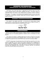
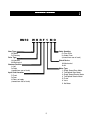
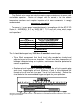
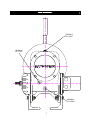
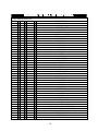
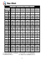
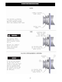
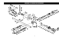
DESIGN SERIES 001
RUFNEK 10
AND
MODEL 1138
SERVICE MANUAL
GENERAL INFORMATION .......................................................................................................................... 4
INTRODUCTION AND THEORY OF OPERATION.................................................................................................................. 4
ASSEMBLY NUMBER EXPLANATION ................................................................................................................................... 4
WINCH BREAK-IN .................................................................................................................................................................. 4
MODEL CODE .............................................................................................................................................. 5
MAINTENANCE............................................................................................................................................ 6
OIL LEVELS............................................................................................................................................................................ 7
BRAKE ADJUSTMENT ........................................................................................................................................................... 8
DISASSEMBLY ............................................................................................................................................ 8
BRAKE DISASSEMBLY .......................................................................................................................................................... 8
CLUTCH AND DRUM DISASSEMBLY .................................................................................................................................... 9
GEARBOX DISASSEMBLY..................................................................................................................................................... 9
GEAR INSPECTION INSTRUCTIONS .................................................................................................................................... 10
ASSEMBLY ................................................................................................................................................ 11
GEARBOX ASSEMBLY .......................................................................................................................................................... 11
BRAKE ASSEMBLY................................................................................................................................................................ 11
CLUTCH AND DRUM ASSEMBLY .......................................................................................................................................... 12
TROUBLESHOOTING................................................................................................................................ 13
RUFNEK 10 BILL OF MATERIAL ............................................................................................................. 14
TORQUE SPECIFICATIONS CHART ........................................................................................................ 16
CLUTCH INSPECTION .............................................................................................................................. 17
RUFNEK 10 ISOMETRIC DRAWING ........................................................................................................ 18
SEL-0043-001.DOC
REV-0
FAILURE TO HEED THE FOLLOWING WARNINGS MAY RESULT IN
SERIOUS INJURY OR DEATH.
The safety of the winch operator and ground personnel should always be of great
concern, and all necessary precautions to insure their safety must be taken. The
primary mover and the winch must be operated with care and concern for the
equipment and the environment and with a thorough knowledge of the equipment and
its performance capabilities must be understood. These general safety guidelines are
offered, however local rules and regulations or national standards may also apply.
Recommended references are, but not limited to, ANSI B30, OSHA 1910, AWS D 14.3,
and SAE J706.
Additional information can be found at http://www.team-twg.com/TulsaWinch/
Indicates an imminently hazardous situation
which, if not avoided, will result in death or serious
injury.
Indicates a potentially hazardous situation which,
if not avoided, could result in death or serious
injury.
Indicates a potentially hazardous situation which,
if not avoided, may result in minor or moderate
injury or property damage.
Indicates information or a company policy that
relates directly or indirectly to the safety of
personnel or protection of property.
Mounting:
Winch mounting must be secure and able to withstand the applied loads.
•
•
•
•
The stability of the mounting system must be approved by a qualified person.
All welding should also be done by a qualified person.
Winch mount must be flat so as not to induce binding.
The flatness must not exceed 1/16 inch across the mounting surface of the winch
itself.
Guards must be placed on all open drives in the case of mechanical winches.
Insure that all hydraulic hoses, valves and fittings are rated to winch manufacturer’s
operating pressures.
Relief valves should be set to winch manufacturer’s specifications.
Insure that all PTO’s and drivelines are sized appropriately for the winch manufactures
speed and torque specifications.
2
Operator:
Must read and understand the operating and service manual.
Both the SERVICE MANUAL and OPERATING MANUAL are available online at
http://www.team-twg.com/TulsaWinch/
Must never lift or move people with this winch.
This winch is not designed or intended for any use that involves moving people.
Must stay clear of the load at all times.
Ground personnel should remain a safe distance from the load and winch cable
at least 1 ½ times the length of cable measured from the winch to the load.
Must stay clear of the cable at all times.
A broken cable can cause serious injury or death.
Must avoid shock loads.
Shock loads can impose a strain on the winch that can be many times the design
rating.
Must be aware of the fleet angle of the winch.
All loads should only be pulled with the load line perpendicular to the drum shaft,
this is to avoid excessive stresses on the winch and will help prevent the cable
from building on one side of the drum flange.
Must wear personnel protective equipment (PPE) if required.
Check the local, state and federal regulations for compliance.
Must insure that the drum clutch is fully engaged before hoisting.
A visual inspection of the drum clutch engagement is required before each
winching operation.
Must rig all loads secure before winching.
Pull the load line taut and inspect the condition of load for stability.
Must inspect the drum brake if equipped.
The drum brake is not a load holding device it is design to prevent over spooling
of the drum and causing bird nesting of the cable on the drum. Inspect the brake
for wear of the lining and the actuation method.
Must inspect the load control brake.
These winches can be equipped with two (2) forms of dynamic braking. The
worm brake is one method and is adjustable for pay-out load control. Before a
load is handled the load should be pulled tight and stopped to check this brake.
The second method is a hydraulic lowering control that is not field adjustable.
The same method should be used to check this brake.
Operation:
•
•
•
•
•
•
All winch controls must be well marked for function to avoid confusion.
Insure that the PTO is disengaged when the winch is not in use.
All winch controls must be located to provide the operator with a clear view of the
load.
The clutch must be inspected daily for proper operation.
The winch cable should be inspected daily for serviceability.
A minimum of five wraps of tightly wound cable must remain on the drum.
3
GENERAL INFORMATION
INTRODUCTION AND THEORY
THEORY OF OPERATION
The Rufnek series worm gear winch is operated by turning the input of the worm
using a hydraulic motor or PTO driven sprocket and chain. The winch utilizes an
adjustable brake that activates only during pay-out to provide maximum efficiency
during pay-in. The torque is transferred from the gearbox through the drum shaft which
is keyed to a mechanically actuated sliding clutch that when engaged transfers the
torque to the drum.
ASSEMBLY NUMBER EXPLANATION
EXPLANATION
This manual is for design series 001. In the case of a major design change
implementation, a new design series designation number will be issued for the winch. A
new manual will also be created for that specific design series.
ASSEMBLY #
DESIGN
SERIES
81276 001
WINCH BREAKBREAK-IN
Winches, like any other kind of machinery, require a “break-in” to perform well and to
maximize their life. The following guidelines should be used in the break-in of Tulsa
Winches.
Use extreme care when first spooling cable onto the winch. DO NOT run the winch
at high speeds when performing this operation. Make sure that the cable is payed-out in
a straight line (to prevent kinks) and SLOWLY pay-in the winch to install the cable.
DO NOT exceed one half rated load or one half rated line speed for the first thirty
minutes of operation. This will insure that the worm and gear have an opportunity to
wear in properly. Periodically, check the gearbox for temperature rises and allow the
winch to cool down between pulls. Worm gear winches are designed and intended for
intermittent duty application only; using them in extremely long pulls may generate
excessive heat and shorten the life of the winch.
4
MODEL CODE
RN10
WH RF 1 MO
Cable Spooling
O=Over Drum
U=Under Drum
(viewed from rear of truck)
Gear Type
W=Worm
P=Planetary
Drive Type
H=Hydraulic
M=Mechanical
Gearbox Position
L=Left
R=Right
(viewed from rear of truck)
Input Shaft Location
F=Front
R=Rear
X=Does not apply
(viewed from rear of truck)
Clutch Device
M=Mechanical
A=Air
Motor Type
1. Single Speed Gear Motor
2. Two Speed Gear Motor
3. Single Speed Geroler Motor
4. Two Speed Geroler Motor
5. Piston
6. Vane
X. No Motor
5
MAINTENANCE
Tulsa Rufnek series worm gear winches require regular maintenance to ensure safe
and reliable operation. Routine oil changes with the correct oil for the ambient
temperature conditions and a regular inspection of the wear components is strongly
recommended.
Maintenance Scheduling
The owner is to insure proper inspection intervals, in compliance with the API RP 2D
Section 4, ANSI B30.5, 5-2.3 or ANSI B30.7, 7-2.1, and will review winch usage
categories on a periodic basis. A qualified inspector should perform all maintenance
and inspections.
USE
(HRS PER MONTH)
0-10
11-50
51+
API RP 2D RECOMMENDED
INSPECTION SCHEDULE
PRE-USE, ANNUAL
PRE-USE, QUARTERLY
PRE-USE, MONTHLY
Oil Maintenance
The oil should be changed every 1000 hrs or 6 months of normal usage.
•
Tulsa Winch recommends that the oil level in the gearbox be checked and
adjusted as part of the pre-use inspection. If the oil level drops frequently or oil
leakage is detected during an inspection, maintenance should be performed to
correct any problems.
OIL CAPACITY = .75 QTS
•
Gearbox oil level inspection is achieved by removing the oil level inspection plug
and visually inspecting the oil level. Minimum oil level is to the bottom of the
threads of the oil level hole (see page 7 for oil level hole location). Refer to the
chart below for the recommended oil type and grade for your application.
SAE 140W AGMA 7 EP
MOBIL SHC 626
MOBILUBE HD80W140
All oils must meet MIL-PRF2105E standards. Substitution from a reputable manufacturer is allowed as long as type
and grade are maintained.
6
OIL LEVELS
GEARBOX
FILL/VENT
GEARBOX
OIL LEVEL
GEARBOX
OIL DRAIN
7
MAINTENANCE
CONTINUED
BRAKE ADJUSTMENT
This brake uses a one way cam clutch
(49) allowing free spooling in the in-haul
direction and engages in the payout
direction. To increase the brake torque,
follow the steps listed below.
The brake should be adjusted to hold
no more than the winch rating. If the
brake
does
not
respond
to
adjustment, the brake must be
disassembled and inspected per
brake disassembly section of this
manual.
1. Loosen the locknut (53).
2. Increase the brake torque by turning
the adjusting screw (52) clockwise.
Excessive brake torque can cause
over heating and premature wear.
3. Tighten the locknut (53) after the
brake adjustments are completed.
DISASSEMBLY
BRAKE DISASSEMBLY
1. Remove the bottom plug (34) to
drain the oil.
6. Inspect parts as follows, replace if
necessary:
2. Loosen the locknut (53) and brake
adjusting screw (52) to reduce spring
force on brake housing (45).
A. Inspect the friction discs (47) for
excessive wear. Friction discs
should measure no less than
.065-in thick.
3. Remove the capscrews (56) from the
brake housing (45).
B. Inspect the flat surfaces of the
brake hub (46), stator plates (48),
and thrust plate (51) for warpage,
excessive wear, or other damage.
4. Remove the brake housing (45),
thrust washer (51), and spring (50)
from the gearbox.
C. Examine the spring (50) for any
discoloration.
5. Remove the stator plates (48),
friction discs (47), brake hub (46),
spacer (55), and cam clutch (49)
from the worm (30).
D. The cam clutch (49) should be
free of any debris and have all
rollers intact. If cam clutch needs
to be replaced, a new cam clutch
should be carefully pressed into
the brake hub (46).
Make sure to note the direction
that the cam clutch and brake hub
are installed. They must be reinstalled the same way.
8
CLUTCH AND DRUM DISASSEMBLY
1. Remove the four capscrews (12),
nuts (15), and washers (16)
attaching the end bracket (1) to the
frames (13).
A. Inspect the bushing (19) in the
end bracket (1) for excessive
wear.
B. Inspect the lever assembly (17),
sliding clutch (24), keys (14), and
thrust washer (27) for excessive
wear. See page 14 for clutch
inspection.
2. Remove the end bracket (1), lever
assembly (17), sliding clutch (24),
and keys (14) from the output shaft
(3).
3. Remove the thrust washer (27).
C. Inspect the bores of the drum (2)
for excessive wear or damage.
4. With the support of a hoist, remove
the drum (2).
D. Check the drag brake (8) for
excessive wear.
5. Inspect parts as follows, replace if
necessary:
E. Inspect the oil seal (25) for any
leaks.
GEARBOX DISASSEMBLY
1. Remove the brake from the gearbox.
See brake disassembly section of
this manual.
If the bushing in the gearbox
needs to be replaced, a complete
teardown is necessary.
2. Remove either the motor (23) or the
end cap (58) (depending on type of
drive) by removing two capscrews
(38).
7. Inspect parts as follows, replace if
necessary:
3. Remove the snap ring (32) from the
brake end of the worm.
A. Inspect the worm (30) for
excessive wear, signs of heat
checking, or cracks.
4. From the brake end, push the worm
while rotating it in order to remove
the worm from the gearbox.
B. Inspect the bearings (33) for
excessive wear or damage.
5. Remove the cover (6) from the
gearbox by removing the four
capscrews (11).
C. Inspect the thrust washers (27),
bushing (26), and gear (29) for
excessive wear.
6. Remove the thrust washer (27) and
gear (29).
D. Inspect the keys (28) and output
shaft (3) for damage.
9
GEAR INSPECTION INSTRUCTIONS
LAND
Check gear wear by removing the cover and visually inspecting the bronze gear. If the gear is worn such
that there is no visible land on the throat of the gear between the gear flanks as shown in picture above
the gear should be replaced.
10
ASSEMBLY
GEARBOX ASSEMBLY
1. Install the bushings (26) into the
gearbox (4) and cover (6).
the worm (30) is in place, install the
other bearing (33) and retaining ring
(32) onto the worm (30).
2. Install the thrust washer (27) and
keys (28) onto the output shaft (3).
Slide the gear (29) over the keys (28)
and against the thrust washer (27).
Slide the other thrust washer (27)
onto the output shaft (3).
5. If your winch uses mechanical input,
install a new oil seal (59) into the end
cap (58). Install the end cap with two
capscrews (38).
6. If your winch uses a hydraulic motor.
Install the motor (23) and o-ring (35).
3. Install the cover (6) using the four
capscrews (11), being careful not to
damage the o-ring (10).
7. Fill to the proper oil level with the
recommended lubricant.
See
maintenance section of this manual
on page 6.
4. Install one bearing (33) and retaining
ring (32) onto the end of the worm
(30), then install the worm (30) into
the gearbox (4) engaging the gear
(29) as you push it through. Once
BRAKE ASSEMBLY
1. Insert the following parts into the
brake housing (45) in this order:
•
•
•
•
•
•
•
•
•
3. Tighten the brake adjustment screw
(52) until tension from the spring (50)
is felt. See brake adjusting section
of this manual.
Thrust washer (51)
Spring (50)
Stator plate (48)
Friction disc (47)
Cam clutch/brake
hub assembly (46,49)
Friction disc (47)
Stator plate (48)
Brake spacer (55)
Gasket (21)
Factory preset is 8 ft/lbs @ worm
input
4. Fill to the proper oil level with the
recommended lubricant.
See
maintenance section of this manual
on page 6.
2. Install the brake assembly onto the
gearbox (4) with two capscrews (56).
11
CLUTCH AND DRUM ASSEMBLY
1. If necessary, replace the oil seal (25)
in the gearbox (4)
4. Install the sliding clutch (24), lever
(17), and end bracket (1).
2. Place some grease into the pockets
located on the back of the gearbox
(4) and install the springs (9) and
drag brakes (8). The grease should
hold them in place.
5. Attach the end bracket (1) to the
frames using four capscrews (12),
nuts (15), and washers (16).
6. Install the plug (34) into the bottom of
the gearbox (4). Fill to the proper oil
level with the recommended lubricant
(see page 6 of this manual).
3. Grease the inside of the drum bore
and the output shaft. Install the drum
(2) and thrust washer (27) onto the
output shaft (3).
12
TROUBLESHOOTING
FAILURE
Clutch handle won’t latch
Oil leaks from housing
Load drifts down
Winch runs too slow
Cable drum won’t free spool
PROBABLE CAUSE
a) Clutch jaws aren’t aligned.
jaws by rotating drum.
Align the
b) Damaged yoke or linkage. Replace
damaged parts.
a) Seal damaged or worn. Replace the
seal(s).
b) Too much gearbox oil. Drain excess
oil.
a) Oil-cooled brake out of adjustment or
worn. Adjust brake until load doesn’t
drift. Replace the parts as required.
a) Low flow rate. Check the flow rate and
increase if necessary.
b) Hydraulic motor worn out. Replace the
motor.
a) Winch not mounted squarely. Check
mounting and confirm that the winch is
mounted on a flat surface.
b) Clutch not disengaged. Disengage the
clutch.
Cable birdnests when clutch is a) Drag brakes are worn. Replace the
disengaged.
drag brakes.
Hydraulic fluid leaks from the gearbox
a) Damaged motor shaft seal. Replace
the seal.
Winch won’t pick up heavy loads.
a) Too much cable on the drum. Use the
snatch block or remove some cable
from the drum.
b) System pressure too low. Increase the
hydraulic system pressure.
c) Winch not broke-in. Run winch at half
of rated load for several pulls.
13
RUFNEK 10 BILL OF MATERIAL
81276001-BOM SEPTEMBER 2005
ITEM
1
2
3
4
5
6a
6b
7
8
9
10
11
12
13
14
15
16
17
17-1
17-2
17-3
17-4
17-5
17-6
17-7
17-8
18
19
20
21
22
23
24
25
26
27
28
29
30a
30b
31
32
33
34
QTY
1
1
1
1
1
1
1
1
3
3
1
4
8
2
2
8
8
1
1
1
1
1
2
1
1
2
-1
-2
1
1
1
1
2
3
2
1
1
1
-2
2
2
P/N
41207
41190
41193
41188
12208
44046
41192
23582
25692
25774
40547
40407
10381
41197
25762
20521
20518
4069
41185
20296
20299
20304
33786
20723
20116
24724
-41238
-40147
13050
40121
20712
11637
41196
40510
40518
41198
40598
40635
-40396
40395
32220
DESCRIPTION
END BRACKET
DRUM
OUTPUT SHAFT
HOUSING
BUSHING
RUFNEK 10W COVER
MODEL 1138 COVER
SET SCREW
DRAG BRAKE
SPRING
O-RING
CAPSCREW
CAPSCREW
FRAME
KEY
NUT
LOCKWASHER
LEVER ASSEMBLY
YOKE
PIN
SPRING
PIN
FLAT WASHER
BRACKET
PIN
RETAINING RING
OMIT
BUSHING
OMIT
GASKET
BREATHER
HYDRAULIC MOTOR
CLUTCH
OIL SEAL
BUSHING
THRUST WASHER
KEY
GEAR
WORM (HYDRAULICALLY DRIVEN)
WORM (MECHANICALLY DRIVEN)
OMIT
RETAINING RING
BEARING
PLUG
14
RUFNEK 10 BILL
BILL OF MATERIAL
35
36
37
38
39
40
41
42
43
44
45
46
47
48
49
50
51
52
53
54
55
56
57
58
59
60
61
62
63
1
--2
2
2
2
1
1
1
1
1
2
2
1
1
1
1
1
1
1
2
-1
1
1
1
1
1
32566
--40410
20270
20271
20526
41244
41250
21128
40069
40617
40075
40076
40113
40077
40078
40775
40774
29044
40599
40546
-40082
20232
20105
20092
20278
44024
CONTINUED
O-RING
OMIT
OMIT
CAPSCREW
CAPSCREW
NUT
LOCKWASHER
C.T.O. HANDLE
HANDLE GRIP
GREASE ZERK
BRAKE HOUSING
BRAKE HUB
FRICTION DISC
STATOR PLATE
CLUTCH CAM
SPRING
THRUST WASHER
SET SCREW
LOCKNUT
WASHER
BRAKE SPACER
CAPSCREW
OMIT
END CAP
OIL SEAL
KEY
WASHER
CAPSCREW
RUFNEK PLATE
15
TORQUE SPECIFICATIONS
SPECIFICATIONS CHART
Dry
SAE
Grade 5
Torque
*(Ft-Lbs)
Plated
SAE
Grade 5
Torque
*(Ft-Lbs)
Lubricated
SAE
Grade 5
Torque
*(Ft-Lbs)
Dry
SAE
Grade 8
Torque
*(Ft-Lbs)
Plated
SAE
Grade 8
Torque
*(Ft-Lbs)
Lubricated
SAE
Grade 8
Torque
*(Ft-Lbs)
Nominal
Size
1/4
20
8
6
5
12
9
7
1/4
28
10
7
6
14
10
8
5/16
18
17
13
10
25
18
15
5/16
24
19
14
11
27
20
16
3/8
16
31
23
19
44
33
26
3/8
24
35
26
21
49
37
30
7/16
14
49
37
30
70
53
42
7/16
20
55
41
33
78
58
47
1/2
13
76
57
45
106
80
64
1/2
20
85
64
51
120
90
72
9/16
12
109
82
65
153
115
92
9/16
18
122
91
73
172
129
103
5/8
11
150
113
90
212
159
127
5/8
18
170
128
102
240
180
144
3/4
10
266
200
160
376
282
226
3/4
16
297
223
178
420
315
252
7/8
9
430
322
258
606
454
364
7/8
14
474
355
284
668
501
401
1
1
8
644
483
386
909
682
545
14
721
541
433
1019
764
611
1-1/8
7
794
596
475
1288
966
772
1-1/8
12
890
668
534
1444
1083
866
1-1/4
1-1/4
7
12
1120
1241
840
930
672
745
1817
2012
1363
1509
1090
1207
T = BOLT TORQUE (LB. FT.)
T = (KWD) / 12
K = TORQUE COEFFICIENT (K = 0.20 DRY
K = 0.15 PLATED
K = 0.12 LUBRICATED)
W = PRELOAD TENSION
D = NOMINAL BOLT SIZE (IN.)
* ALL TORQUE VALUE TOLERANCES ARE ± 5%
16
CLUTCH INSPECTION
17
RUFNEK 10 ISOMETRIC DRAWING
18