1
Bulletin HY25-1135-M1/US
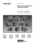
Owner’s Manual
Power Take-Offs
Effective:
January 2008
Supersedes: HY25-1135-M1/US
September 2007
100
221
260
290
340
352
435
Series
Series
Series
Series
Series
Series
Series
436
437
438
442
447
452
489
Series
Series
Series
Series
Series
Series
Series
660
680
812
823
863
880
Series
Series
Series
Series
Series
Series
WARNING
FAILURE OR IMPROPER SELECTION OR IMPROPER USE OF THE PRODUCTS AND/OR SYSTEMS DESCRIBED
HEREIN OR RELATED ITEMS CAN CAUSE DEATH, PERSONAL INJURY AND PROPERTY DAMAGE.
This document and other information from Parker Hannifin Corporation, its subsidiaries and authorized distributors
provide product and/or system options for further investigation by users having technical expertise. It is important
that you analyze all aspects of your application and review the information concerning the product or system in the
current product catalog. Due to the variety of operating conditions and applications for these products or systems,
the user, through its own analysis and testing, is solely responsible for making the final selection of the products and
systems and assuring that all performance, safety and warning requirements of the application are met.
The products described herein, including without limitation, product features, specifications, designs, availability and
pricing, are subject to change by Parker Hannifin Corporation and its subsidiaries at any time without notice.
Offer of Sale
The items described in this document are hereby offered for sale by Parker Hannifin Corporation, its subsidiaries or
its authorized distributors. This offer and its acceptance are governed by the provisions stated in the "Offer of Sale".
Patent Information
®
The Chelsea Power Take-Off or its components shipped with this owner’s manual may be manufactured under one
or more of the following U.S. patents:
4610175
5228355
4597301
5645363
6151975
6142274
6260682
7159701 B2
Other patents pending.
© Copyright 2008, Parker Hannifin Corporation, All Rights Reserved
II
Parker Hannifin Corporation
Chelsea Products Division
Olive Branch, MS 38654 USA
Bulletin HY25-1135-M1/US
Contents
Owner’s Manual
6 and 8 Bolt P.T.O.s
General Information
Safety Information ........................................................................................................... 1-3
Direct Mount Pump Support Recommendations ............................................................... 4
Foreword ......................................................................................................................... 5
P.T.O. Safety Labels Installation ...................................................................................... 5
Installation Instructions
Dodge/Sterling Overview ................................................................................................. 7-8
Wiring Chart Model Year 2007 Dodge Chassis Cab w/G56 Transmission .......................... 9
GMT3600 Cab-Chassis w/ZF .......................................................................................... 10-18
Mounting P.T.O. to Transmission 6 & 8 Bolts ................................................................... 19-20
880/912 Split Shaft Installation ........................................................................................ 21
Checking Backlash .......................................................................................................... 22-23
Adapter Plates, Filler Blocks, Adapter Assembly ............................................................ 24
Lubricant in Transmission/Inspect Installation ................................................................... 25
Function of Auxiliary Power Shafts .................................................................................. 26
Spicer Universal Joint Engineering Data Quick Reference ............................................... 27
Wire Shift P.T.O.
Continuity Check (379639 & 379652 indicator switches) .................................................. 28
Cable Control Installation ................................................................................................. 29-33
Automatic Transmissions
Pressure Lube Hose Connection ...................................................................................... 34
442 Series Pressure Lube for Allison 1000, 2000/2400 Series .......................................... 35
P.T.O. Openings for Automatic Transmissions ................................................................. 36-38
P.T.O. Shifting Procedure ................................................................................................ 39
Air Shift P.T.O. Installation Sketch
340 and 352 Series .......................................................................................................... 40
880, 823 Series ............................................................................................................... 41
100, 221, 260, 429, 434, 435, 436, 437, 438, 442,
447, 489, 660, 680 and 812 Series ................................................................................... 42
Electric Over Air Shift P.T.O. Installation Sketch
100, 221, 260, 429, 434, 435, 436, 437, 438, 442,
447, 489, 660, 680 and 812 Series ................................................................................... 43
Installing Rotatable Flange ............................................................................................... 44
Indicator Light Installation ............................................................................................... 45
Dash Drilling Templates .................................................................................................... 45-47
P.T.O. Maintenance ............................................................................................................ 48
Offer of Sale ....................................................................................................................... 52
Loose In This Booklet
Mounting Gaskets
Sun Visor Decal
III
Parker Hannifin Corporation
Chelsea Products Division
Olive Branch, MS 38654 USA
Bulletin HY25-1135-M1/US
General Information
Owner’s Manual
6 and 8 Bolt P.T.O.s
Safety Information
These instructions are for your safety and the safety of the end user. Read them carefully until
you understand them.
General Safety Information
To prevent injury to yourself and/or damage to the equipment:
■ Read carefully all owner’s manuals, service manuals, and/or other instructions.
■ Always follow proper procedures, and use proper tools and safety equipment.
■ Be sure to receive proper training.
■ Never work alone while under a vehicle or while repairing or maintaining equipment.
■ Always use proper components in applications for which they are approved.
■ Be sure to assemble components properly.
■ Never use wornout or damaged components.
■ Always block any raised or moving device that may injure a person working on or under a
vehicle.
■ Never operate the controls of the Power Take-Off or other driven equipment from any position
that could result in getting caught in the moving machinery.
Proper Matching of P.T.O.
WARNING: A Power Take-Off must be properly matched to the vehicle transmission and
to the auxiliary equipment being powered. An improperly matched Power Take-Off could cause
severe damage to the vehicle transmission, the auxiliary driveshaft, and/or to the auxiliary
equipment being powered. Damaged components or equipment could malfunction causing
serious personal injury to the vehicle operator or to others nearby.
To avoid personal injury and/or equipment damage:
■ Always refer to Chelsea catalogs, literature, and owner’s manuals and follow Chelsea
recommendations when selecting, installing, repairing, or operating a Power Take-Off.
■ Never attempt to use a Power Take-Off not specifically recommended by Chelsea for the
vehicle transmission.
■ Always match the Power Take-Off’s specified output capabilities to the requirements of the
equipment to be powered.
■ Never use a Power Take-Off whose range of speed could exceed the maximum safe speed
of the equipment to be powered.
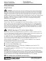
This symbol warns of possible personal injury.
1
Parker Hannifin Corporation
Chelsea Products Division
Olive Branch, MS 38654 USA
Bulletin HY25-1135-M1/US
General Information
Owner’s Manual
6 and 8 Bolt P.T.O.s
Safety Information
Cold Weather Operation of Powershift P.T.O.s
WARNING: During extreme cold weather operation [32° F (0° C) and lower], a
disengaged Powershift Power Take-Off can momentarily transmit high torque that will cause
unexpected output shaft rotation. This is caused by the high viscosity of the transmission oil
when it is extremely cold. As slippage occurs between the Power Take-Off clutch plates, the
oil will rapidly heat up and the viscous drag will quickly decrease.
The Power Take-Off output shaft rotation could cause unexpected movement of the driven
equipment resulting in serious personal injury, death, or equipment damage.
To avoid personal injury or equipment damage:
■ Driven equipment must have separate controls.
■ The driven equipment must be left in the disengaged position when not in operation.
■ Do not operate the driven equipment until the vehicle is allowed to warm up.
Rotating Auxiliary Driveshafts
WARNING:
■ Rotating auxiliary driveshafts are dangerous. You can snag clothes, skin, hair, hands, etc.
This can cause serious injury or death.
■ Do not go under the vehicle when the engine is running.
■ Do not work on or near an exposed shaft when the engine is running.
■ Shut off the engine before working on the Power Take-Off or driven equipment.
■ Exposed rotating driveshafts must be guarded.
Guarding Auxiliary Driveshafts
WARNING: We strongly recommend that a Power Take-Off and a directly
mounted pump be used to eliminate the auxiliary driveshaft whenever possible. If an
auxiliary driveshaft is used and remains exposed after installation, it is the responsibility of
the vehicle designer and P.T.O. installer to install a guard.
This symbol warns of possible personal injury.
2
Parker Hannifin Corporation
Chelsea Products Division
Olive Branch, MS 38654 USA
Bulletin HY25-1135-M1/US
General Information
Owner’s Manual
6 and 8 Bolt P.T.O.s
Safety Information
Using Set Screws
WARNING: Auxiliary driveshafts may be installed with either recessed or protruding
set screws. If you choose a square head set screw, you should be aware that it will protrude
above the hub of the yoke and may be a point where clothes, skin, hair, hands, etc. could be
snagged. A socket head set screw, which may not protrude above the hub of the yoke, does
not permit the same amount of torquing as does a square head set screw. Also, a square head
set screw, if used with a lock wire, will prevent loosening of the screw caused by vibration.
Regardless of the choice made with respect to a set screw, an exposed rotating auxiliary
driveshaft must be guarded.
Important: Safety Information and Owner’s Manual
Chelsea Power Take-Offs are packaged with safety information decals, instructions, and an
owner’s manual. These items are located in the envelope with the P.T.O. mounting gaskets.
Also, safety information and installation instructions are packaged with some individual parts
and kits. Be sure to read the owner’s manual before installing or operating the P.T.O. Always
install the safety information decals according to the instructions provided. Place the owner’s
manual in the vehicle glove compartment.
WARNING: Operating the P.T.O. with the Vehicle in Motion
Some Power Take-Offs may be operated when the vehicle is in motion. To do so, the P.T.O.
must have been properly selected to operate at highway speeds and correctly matched to the
vehicle transmission and the requirements of the driven equipment.
If in doubt about the P.T.O.’s specifications and capabilities, avoid operating the P.T.O. when
the vehicle is in motion. Improper application and/or operation can cause serious personal
injury or premature failure of the vehicle, the driven equipment, and/or the P.T.O.
Always remember to disengage the P.T.O. when the driven equipment is not in operation.
Pump Installation Precautions (see next page)
Use a bracket to support the pump to the transmission if:
■ The pump weighs 40 pounds or more.
■ The combined length of the P.T.O. and pump is 18 inches or more from the P.T.O.
centerline to the end of the pump.
Also remember to pack the female pilot of the P.T.O. pump flange with grease before installing
the pump on the P.T.O.
CAUTION: When installing the 489 Series P.T.O. several direct mount pump flange options
may interfere with the mounting fasteners directly under the flange. The nut must be threaded
far enough onto the stud before the remaining (6) six capscrews and other nut are tightened to
prevent interference with the flange and possible breakage of the P.T.O. housing.
This symbol warns of possible personal injury.
3
Parker Hannifin Corporation
Chelsea Products Division
Olive Branch, MS 38654 USA
Bulletin HY25-1135-M1/US
General Information
Owner’s Manual
6 and 8 Bolt P.T.O.s
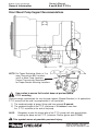
Direct Mount Pump Support Recommendations
NOTE: For Proper Bracketing Attach at 2 or
more Transmission Bolt Locations
and 2 or More Pump Locations.
Contact Transmission Manufacture
for Proper Bracket Mounting Locations.
Use caution to ensure that bracket does not pre-load pump/
P.T.O. mounting
Chelsea strongly recommends the use of pump supports (Support Brackets) in all applications.
P.T.O. warranty will be void if a pump bracket is not used when:
1) The combined weight of pump, fittings and hose exceed 40 pounds.
2) The combined length of the P.T.O. and pump is 18 inches or more from
the P.T.O. centerline to the end of the pump.
ALSO:
Remember to pack the female pilot of the P.T.O. pump shaft with grease before
installing the pump on the P.T.O. (reference Chelsea grease pack 379688)
This symbol warns of possible personal injury.
4
Parker Hannifin Corporation
Chelsea Products Division
Olive Branch, MS 38654 USA
Bulletin HY25-1135-M1/US
General Information
Owner’s Manual
6 and 8 Bolt P.T.O.s
Foreword
Since it is our major objective to show you how to get additional and more profitable miles
from truck, tractor, and trailer components, we want to provide you with information on the
installation of Chelsea Power Take-Offs.
We all realize that an inadequate transmission will overwork any power take-off in a very
short period of time. In addition, a mismatched transmission/P.T.O. combination can result in
unsatisfactory performance of the equipment right from the start.
Before you order new trucks, be sure that you’re getting the right transmission/P.T.O.
combination. This is vital for efficient performance and adequate power. To help you select
the proper type, size, and design of P.T.O., discuss your specific requirements with a
Chelsea P.T.O. specialist. They know their products and have easy access to equipment,
transmission, and Power Take-Off manufacturers. They can tell you everything you need to
know about power, at the right time, before you specify components.
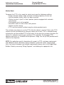
Chelsea P.T.O. Safety Label Instructions
1. The two black and orange on white 5" x 7" pressure sensitive vinyl labels, part number
379274; must be placed on the vehicle frame rails (one (1) on each side), in a position
that would be HIGHLY visible to anyone that would go under the truck near the P.T.O.
rotating shaft. If the vehicle is to be painted after these labels are installed, cover them
with two-(2) blank masking covers. Remove the masking covers after painting.
2. Place the one (1) black and orange on white 3.5" x 5" pressure sensitive vinyl label, part
number 379275, on the visor nearest the operator of the vehicle, this must be placed
near the P.T.O. visor label.
3. Place the one (1) red and white with black lettering 3.5" x 7.5" sensitive vinyl label, part
number 379915, on the opposite side of the visor from the above label # 379275.
4. Place the one (1) white and black heavy duty card, part number 379276, in the vehicle
glove box. Again in a position highly visible to the operator, for example: try to place this
card on top of whatever may be in the glove box.
If you require additional labels, please order part number 328946X at no charge from your
local Chelsea Warehouse or send request direct to:
Parker Hannifin Corporation
Chelsea Products Division
8225 Hacks Cross Road
Olive Branch, MS 38654
Customer Service: (662) 895-1011
5
Parker Hannifin Corporation
Chelsea Products Division
Olive Branch, MS 38654 USA
Bulletin HY25-1135-M1/US
General Information
Owner’s Manual
6 and 8 Bolt P.T.O.s
6
Parker Hannifin Corporation
Chelsea Products Division
Olive Branch, MS 38654 USA
Bulletin HY25-1135-M1/US
Installation Instructions
Owner’s Manual
6 and 8 Bolt P.T.O.s
Dodge/Sterling Overview
P.T.O. Operation
The 3500/4500/5500 Dodge Chassis Cab vehicle, when equipped with either the automatic
Aisin 6 speed or manual G-56 6 speed transmissions, will allow for an aftermarket upfit with
a transmission driven P.T.O. (Power Take-Off). The customer will have the ability to operate
the P.T.O. in either a “stationary” or “mobile” mode. The vehicles will be factory set to the
“stationary” mode. In order to select the “mobile” mode a DaimlerChrysler Dealership is
required to modify the vehicles settings using their proprietary Dealer service tool.
Stationary Mode
To operate the P.T.O. in this mode the vehicle must meet the following conditions:
• Be in “park” positions (vehicles equipped with automatic transmission)
• Up fitter provider (on/off) switch has been activated
• Parking brake applied (vehicles equipped with manual transmission)
• Vehicle must be running
• No vehicle, brake or clutch switch faults present
• P.T.O. must be correctly installed using the vehicle provided circuits
The customer has the choice to operate the P.T.O. by utilizing the cruise control switches or
by utilizing a remote control (provided by the P.T.O. supplier). To operate the feature using
the cruise control switches the customer must first activate the up fitter provided on/off
switch. Next, the cruise control “on” switch is selected. Following this step the “set” switch
must be depressed. The vehicle is now in the P.T.O. mode and is ready for use. In order to
increase or decrease the engine idle speed, to optimize the P.T.O. function, the “accel” and
“decel” cruise switches can be used respectively. To disengage P.T.O. operation and return
to “standard vehicle operation” simply turn the up fitter provided on/off switch to the off
position.
To operate the P.T.O. via a remote switch the customer must make sure the above
conditions are met. It is vital for proper operation that the P.T.O. and remote have been
installed correctly paying special attention to ensure the vehicle provided wiring has been
connected properly. This is the responsibility of the installer of the P.T.O. and switches/
remote system. It is the responsibility of the P.T.O. manufacturer to ensure that their
electrical (switches and remote) system is compatible with the vehicle's electrical architecture and software functionality.
7
Parker Hannifin Corporation
Chelsea Products Division
Olive Branch, MS 38654 USA
Bulletin HY25-1135-M1/US
Installation Instructions
Owner’s Manual
6 and 8 Bolt P.T.O.s
Mobile Mode
To operate the P.T.O. in this mode the vehicle must meet the following conditions:
• Dealer selected “mobile” mode activated via Dealer proprietary service tool
• Up fitter provider (on/off) switch has been activated
• Vehicle must be in “park” or “drive” position (vehicles equipped with automatic
transmission)
• Parking brake must not be applied
• No vehicle, brake or clutch switch faults present
• Vehicle must be running
• P.T.O. must be correctly installed using the vehicle provided circuits
The customer may choose to use the P.T.O. while the vehicle is moving. To do so the P.T.O.
function must be activated prior to taking the vehicle out of “park”. This is accomplished by
activating the up fitter provided P.T.O. on/off switch. At this point the customer may place the
vehicle in a forward or reverse gear and have P.T.O. operation. To disengage P.T.O.
operation and return to “standard vehicle operation” simply turn the up fitter provided on/off
switch to the off position.
NOTE: For application specific information with respect to P.T.O. and pump requirements
and additional vehicle information (wiring schematics, preset idle values, engine speed
limits, and vehicle hardware and software requirements) please refer to the Dodge Body
Builders Guide by accessing “Wiring Diagrams” and choosing the appropriate links.
8
Parker Hannifin Corporation
Chelsea Products Division
Olive Branch, MS 38654 USA
Bulletin HY25-1135-M1/US
Installation Instructions
Owner’s Manual
6 and 8 Bolt P.T.O.s
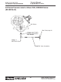
Wiring Chart - Model Year 2007/2008 Dodge/Sterling Chassis Cab,
6.7L w/G56 Transmission
Chelsea Wire
Connected to Dodge Wire
Location
1 Violet
G425 Violet w/ Yellow Stripe
Upfitter Connector
2 Pink
F922 Pink w/Red Stripe
Upfitter Connector
3 Violet
G425 Violet w/ Yellow Stripe
Unterminated Wires
Near Master Cylinder
4 Pink
K425 Pink w/ Yellow Stripe
Unterminated Wires
Near Master Cylinder
5 Violet
V937 Violet w/Brown Stripe
Unterminated Wires
Near Master Cylinder
6 Pink
F922 Pink w/Red Stripe
Unterminated Wires
Near Master Cylinder
Chelsea Wire
Connected to
Location
7 Black w/Booted Connector Pressure Switch
P.T.O.
NOTE: Wire Numbers on this Chart are for reference only.
Wiring Installation 442 Series w/o E.O.C. (SK-433 Rev A)
1
2
7
▼
▼
6
5
4
3
329460X Wiring Harness
68-P-18
Relay
9
Parker Hannifin Corporation
Chelsea Products Division
Olive Branch, MS 38654 USA
Bulletin HY25-1135-M1/US
Installation Instructions
Owner’s Manual
6 and 8 Bolt P.T.O.s
GMT3600 Cab-Chassis W/ZF
Overview
P.T.O. provisions have been provided as standard content (“forced” options) on the
2001MY C/K 3600 (Cab-Chassis) trucks with 8.1L Vortec and 6.6L Durmax Diesel
engines. These provisions are included in two “forced” options, M1F and P.T.O. M1F
contains provisions for P.T.O. packaging. P.T.O. contains provisions for P.T.O. Engagement
Control and P.T.O. Engine Speed Control. Both options are standard on the C/K 3600
cab-chassis trucks with the 8.1L and 6.6L engines.
M1F-provides for mounting space for transmission mounted Power Take-Off. P.T.O.
mounting space is for the right hand side of the transmission. With the ZF S6-650
manual transmissions there are two (2) openings for P.T.O. applications. The right
opening requires the use of a heat shield, direct mount pumps and hard line hydraulic
tubes for installation along with a Chelsea® 442 Series Power Take-Off.
Left side applications do not require the extra “hardware” for installation, but may not be
usable on 4x4 vehicles due to the transfer case to front axle driveshaft.
P.T.O.-provides Engine Speed Control. P.T.O. includes the following:
• P.T.O. engine control software in Powertrain Control Module (PCM)
• Wiring provisions for in-cab P.T.O. Control Switch
• Upfitter P.T.O. Interface Connector which is located at the left side of the
transmission.
Two P.T.O. operating speed control modes are available with the 8.1L Vortec and 6.6L
Duramax Diesel engine. The PowerTrain Control Module (PCM) may be programmed to
one of the following modes.
• Preset – Up to two* preset P.T.O. operating speeds.
• Variable – Allows variable P.T.O. speeds while vehicle is stationary or moving.
* Requires Cruise Control to control second preset speed.
Refer to GM Truck Owner’s Manual for Complete Information on PCM Operations
10
Parker Hannifin Corporation
Chelsea Products Division
Olive Branch, MS 38654 USA
Bulletin HY25-1135-M1/US
Installation Instructions
Owner’s Manual
6 and 8 Bolt P.T.O.s
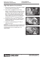
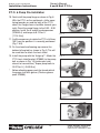
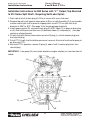
Right Side Aperture Pre-Installation
1. Drain oil from transmission. Drain plug is located
on the left side of the transmission.
2. If the vehicle is equipped with the 8.1L Gas
Engine, it may be necessary to remove the three
(3) bolts & studs that connect the right exhaust
pipe and the right side engine exhaust header.
(Fig. 1) This will allow the exhaust pipe to be
moved slightly away from the P.T.O. opening for
installation of the P.T.O. to the aperture pad.
Fig. 1
3. Remove the transmission P.T.O. aperture cover
and gasket. Make sure the aperture surface is
clean and dry (Fig. 2).
4. Install the six studs and torque to 17-19 lbs. ft.
[23-26 N.m] (Fig. 3).
CAUTION: Over tightening of studs may damage stud
threads or transmission case threads if studs are not
installed correctly. Use of air impact tools is not
recommended.
Fig. 2
Fig. 3
11
Parker Hannifin Corporation
Chelsea Products Division
Olive Branch, MS 38654 USA
Owner’s Manual
6 and 8 Bolt P.T.O.s
Bulletin HY25-1135-M1/US
Installation Instructions
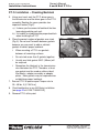
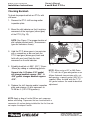
P.T.O. Installation – Checking Backlash
5. Using your hand, rock the P.T.O. driver gear in
the transmission and the driver gear in the P.T.O.
assembly. Rocking the gears provides two
important factors (Fig 4).
a) It shows you the amount of backlash that has
been designed into each unit.
b) It is helpful in establishing the proper backlash
when installing the P.T.O.
6. Place the correct number of gaskets over studs
(Fig. 5). Do not use Permatex between gaskets
because you may want to add or subtract
gaskets to obtain proper backlash.
Fig. 4
• When mounting a P.T.O. use gaskets
between all mounting surfaces.
Do not stack more than 3 gaskets together.
•
• Usually one thick gasket .020" (.50mm) will
Fig. 5
be required.
• Remember the lubricant in the transmission
also lubricates the P.T.O. Therefore, at least
one gasket must be used on either side of
filler blocks, adapter assembly or adapter
plates. More gaskets may be required when
establishing proper backlash.
7. Secure P.T.O. to aperture pad. Torque nuts to
35 – 40 lbs. ft. [47-54 N.m].
8. Check backlash as in any 442 Series installation
[see page 22 of HY25-1135-M1/US].
9. Remove P.T.O. at this point.
12
Parker Hannifin Corporation
Chelsea Products Division
Olive Branch, MS 38654 USA
Bulletin HY25-1135-M1/US
Installation Instructions
Owner’s Manual
6 and 8 Bolt P.T.O.s
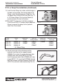
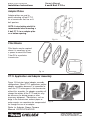
P.T.O. & Pump Pre-Installation
10. Next install the pump flange as shown in Fig. 6.
With the P.T.O. on the workbench, shifter cover
facing towards you and the belly of the P.T.O.
down, the flange shown should be towards your
right. Orient the pump flange to the 3:30 – 9:30
position. Install the 6 socket head capscrews
(378446-4) and torque to 8-12 lbs. ft.
[11-16 N.m].
Fig. 6
11. It will be necessary to rotate the P.T.O. shift lever
180° from the position it is normally positioned
(Fig. 7 & 8).
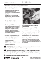
12. On the closed end bearing cap remove the
bottom left cap bolt as shown in Fig. 9. This will
be used later to attach the heat shield.
13. Install the pump with the “bulge up”*. Attach the
P.T.O. heat shield bracket (379862) to the pump
bolt as shown in Fig. 10 (suction port side
closest to transmission). Torque pump bolts to
32-37 lbs. ft. [ 45-50 N.m.]
*
Fig. 7
Before attaching pump, pack the female pilot of
the pump shaft with grease (Chelsea grease
pack 379688).
Fig. 8
Fig. 9
Fig. 10
13
Parker Hannifin Corporation
Chelsea Products Division
Olive Branch, MS 38654 USA
Owner’s Manual
6 and 8 Bolt P.T.O.s
Bulletin HY25-1135-M1/US
Installation Instructions
P.T.O. & Pump Pre-Installation (Continued)
14. Install the two fittings for suction and discharge in
the ports on the pump. Due to the angle of the
fittings, install the discharge port fitting first. Do
not tighten these fittings at this time (See Fig. 11
& 12). Screw fittings in by hand until back-up
washer contacts the face of the boss.
NOTE: CGP-P14 shown for installation purposes.
CGP-P5 and CGP-P11 pumps require additional
fittings to connect the pump to the hydraulic
tubes. See Chart below.
Fig. 11
Fig. 12
Pump
Series
CGP-P5
CGP-P11
CGP-P14
Fitting
Kit
329335-1X
329335-2X
329335-3X
Swivel Nut
Suction
Std Th’d
O-Ring Suction
Swivel Nut
Discharge
379866*
379866*
-
379870
379867
379849*
379868*
-
Std Th’d O-Ring
Discharge
379869
379850*
379850*
* 45° Elbow Fitting
15. We will now move to the attachment of the
hydraulic hard lines to the support bracket
(379848). First attach the pump discharge tube
(379845) with tube clamp (501211-8). Next
install the pump suction tube (379846) with tube
clamp (501211-12). Insert bolt (379706) through
both tube clamps and top of bracket. Tighten nut
(379141-9) onto bolt under bracket (Fig. 13 & 14).
Fig. 13
Fig. 14
14
Parker Hannifin Corporation
Chelsea Products Division
Olive Branch, MS 38654 USA
Bulletin HY25-1135-M1/US
Installation Instructions
Owner’s Manual
6 and 8 Bolt P.T.O.s
Mounting P.T.O./Pump to the Transmission
16. Secure P.T.O./Pump to the transmission. (Fig. 15)
17. Use Self Locking nuts provided with P.T.O. (Fig.16)
NOTE: Self-Locking nuts do not require lock
washers.
18. Fasten the P.T.O. to the transmission (Fig. 17).
Torque the set of self-locking nuts (379744) to
35-40 lbs. ft. [47-54 N.m].
Fig. 15
19. If Installing Engine/P.T.O. Interface Wiring Harness
Kit 329333-4X follow steps 20 & 21.
If not skip to step 22.
Fig. 16
20. Locate the GM upfitter P.T.O. interface connector,
located on the upper left side of the transmission.
Connect Chelsea supplied wiring harness
(379895) to the interface connector (Fig.18).
21. Run wiring harness over top of transmission and
connect the booted connector to the P.T.O.
indicator switch (Fig. 19). See page 17 of this
manual for in dash switch installation. Secure
harness to the transmission to protect the relay
from damage.
Fig. 17
Fig. 18
Fig. 19
15
Parker Hannifin Corporation
Chelsea Products Division
Olive Branch, MS 38654 USA
Bulletin HY25-1135-M1/US
Installation Instructions
Owner’s Manual
6 and 8 Bolt P.T.O.s
Mounting P.T.O./Pump to the Transmission
22. On the right side of the transmission is a bracket
for the oxygen sensor wiring harness (for
California vehicle w/8.1L engines). This bracket
is on all vehicles and may interfere with the
hydraulic tubes. If the oxygen sensor wiring
harness is on the vehicle, bend the bracket in
towards the center of the transmission. If the
vehicle has only the bracket, the bracket may be
removed and the bolt torqued to 17 lbs. ft. [23
N.m]. Do not apply sealant to bolt (Fig. 20).
23. Next attach hydraulic tubes to the pump and
tighten the fittings to the pump and tube nuts
(Fig. 21). Position the fitting by backing out
(counter-clockwise) up to one full turn. Hold
fitting and tubing in desired position and tighten
lock nut with a wrench. Assemble tube to fitting
by tightening the assembly with wrench until
solid feeling is encountered. From that point,
apply one-sixth turn.
Fig. 20
Fig. 21
24. Attach hydraulic tube support bracket (379848)
to the transmission (Fig. 22).
25. Install P.T.O. Heat Shield (379847) to the P.T.O.
(Fig. 23). The heat shield is attached to the
closed bearing cap by re-installing capscrew
(378430-10) to the bearing cap and hex
capscrew (378430-8) to the heat shield support
bracket. Torque 378430-10 to 16-20 lbs. ft.
[22-27 N.m].
Fig. 22
26. Reinstall the three engine exhaust flange studs
and attach pipe with nuts. Torque the nuts to
39 lbs. ft. [50 N.m]
27. Refill transmission with GM recommended fluid.
See page 25 of this manual for complete details.
Fig. 23
28. Refer to page 28-33 of this manual for procedures
on indicator continuity check and cable shift
installation.
16
Parker Hannifin Corporation
Chelsea Products Division
Olive Branch, MS 38654 USA
Bulletin HY25-1135-M1/US
Installation Instructions
Owner’s Manual
6 and 8 Bolt P.T.O.s
P.T.O. Shifting Procedures & Precautions
This vehicle is equipped with a POWER TAKE-OFF
Shut Engine Off Before Working on Power Take-Off or Getting Below Vehicle.
Consult Operating Instructions Before Using. (See Sun Visor)
Power Take-Off Operation Vehicle Stationary
Manual Transmission
1. A Power Take-Off is, and should be, operated as an integral part of the main
transmission.
2. Before shifting the Power Take-Off into or out of gear disengage the clutch and
wait for the transmission or P.T.O. gears to stop rotating
3. Set parking brake
4. Shift the transmission into NEUTRAL (N)
5. Shift P.T.O. into gear
6. Release the clutch pedal
7. * Turn the dash mounted P.T.O./Engine control switch to the ON position. The
engine speed will increase to the P.T.O. Standby Speed.
NOTE: The LED on the P.T.O./Engine control switch will change from blinking to steady
state when the P.T.O. is engaged.
8.
* Press either the SET or Resume switch on the cruise control or turn the P.T.O.
switch to the set position. The engine speed will jump to the P.T.O. SET or
RESUME speeds.
* Optional P.T.O. Interface Wiring Harness/In Dash Switch for Engine Speed Control.
See GM Truck Owner’s Manual for complete engine control speed operations.
IMPORTANT: Failure to follow proper shifting or operating sequences will result in
premature P.T.O. failure with possible damage to other equipment.
WARNING
Do not attempt to work on an installed Power Take-Off with the engine running.
Make sure to block any moving or raised device that may injure a person working
on or under the truck. A lever or its linkage may be accidentally moved causing
movement of the device, which could cause injury to a person near the device.
This symbol warns of possible personal injury.
17
Parker Hannifin Corporation
Chelsea Products Division
Olive Branch, MS 38654 USA
Owner’s Manual
6 and 8 Bolt P.T.O.s
Bulletin HY25-1135-M1/US
Installation Instructions
Connect to
indicator switch
379895
P.T.O. to GM P.T.O. Interface Connector
442 Series w/Wire Shift
18
Parker Hannifin Corporation
Chelsea Products Division
Olive Branch, MS 38654 USA
Bulletin HY25-1135-M1/US
Installation Instructions
Owner’s Manual
6 and 8 Bolt P.T.O.s
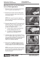
Mounting the P.T.O. on the Transmission
For 6 or 8 Bolt Applications
1. Drain the oil from the transmission and remove
the P.T.O. aperture cover plate (Fig. 1).
2. Discard the cover plate and cover plate gasket
then clean the aperture pad using a putty knife
or wire brush (Fig. 2).
Fig. 1
NOTE: Stuff a rag in the aperture opening to
prevent dirt from entering the transmission while
you are cleaning it.
3. Using your hand, rock the P.T.O. driver gear in the
transmission (Fig. 3) and the driven gear in the
P.T.O. assembly (Fig. 4). Rocking the gears
provides two important factors.
Fig. 2
a) It shows you the amount of backlash that
has been designed into each unit.
b) It is helpful in establishing the proper
backlash when installing the P.T.O.
4. Install the proper studs (furnished with P.T.O.) in
the P.T.O. aperture pad using a stud driver. Studs
may have either interference fit threads (plain) or
preapplied locking/sealing compound (See
Figure 5 for installation method).
5. Where holes are tapped through the transmission case, use studs with preapplied locking &
sealing compound Locktite 290 to prevent leaks.
Fig. 3
Fig. 4
NOTE: Avoid contact of Permatex with automatic
transmission fluid in automatics. Always check to
be sure that the studs do not interfere with
transmission gears.
Fig. 5
19
Parker Hannifin Corporation
Chelsea Products Division
Olive Branch, MS 38654 USA
Bulletin HY25-1135-M1/US
Installation Instructions
Owner’s Manual
6 and 8 Bolt P.T.O.s
Mounting the P.T.O. on the Transmission (Continued)
6. Tighten studs securely and torque to 17-19
lbs. ft. (2.35-2.63 kg meters) for 6 bolt and
19-21 lbs. ft. (2.63-2.90 kg meters) for 8
bolt. CAUTION: overtightening of studs
may damage stud and/or transmission
threads (Fig. 6).
7. Place the correct number of gaskets over
studs (Fig. 7). Do not use Permatex
between gaskets because you may want to
add or subtract gaskets to obtain proper
backlash.
• When mounting a P.T.O. use gaskets
between all mounting surfaces.
• Do not stack more than 3 gaskets
together.
• Usually one thick gasket .020 (.50mm)
will be required.
• Remember the lubricant in the transmission also lubricates the P.T.O. Therefore,
at least one gasket must always be used
on either side of filler blocks, adapter
assemblies or adapter plates. More
gaskets may be required when establishing
proper backlash.
8. Secure P.T.O. to the transmission.
• Use Self Locking nuts provided with P.T.O.
(Fig. 8). NOTE: Self Locking nuts do
not require lock washers.
9. Fasten the P.T.O. to the transmission (Fig.
9). Torque the set of locking nuts to their
proper specifications.
• 379744-3/8"-24 for 6-bolt applications
35-40 lbs. ft. (4.83-5.52 kg.m)
• 379745-7/16"-20 for 8-bolt applications
55-60 lbs. ft. (7.59-8.28 kg.m)
Torque capscrews to their proper
specifications.
• 6-bolt to 30-35 lbs. ft. (4.14-4.84 kg.m)
• 8-bolt to 45-50 lbs. ft. (6.22-6.91 kg.m)
20
Fig. 6
Fig. 7
Fig. 8
Fig. 9
Parker Hannifin Corporation
Chelsea Products Division
Olive Branch, MS 38654 USA
Bulletin HY25-1135-M1/US
Installation Instructions
Owner’s Manual
6 and 8 Bolt P.T.O.s
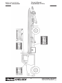
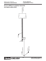
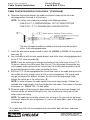
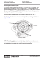
Installation Instructions for 880 Series with “L*” Output, Top Mounted
to 912 Series Split Shaft - Requiring Self-Lube Option
1. Drain split shaft oil at drain plug (A). Filter or screen oil & reuse if desired.
2. Remove top split shaft aperture cover plate at (B) or air shift Assembly (C) & reassemble
to either side of split shaft in place of shipping cover. Install P.T.O. on split shaft & set
backlash at .006" to .012". (See page 19 for checking proper backlash)
3. Install copper gasket (D), screened strain plug (E) & 90° elbow (F) in place of drain plug
at (A). Also install pressure lube hose (G) between elbow (F) and pump (H). (Use pipe
sealant on all pipe threads)
4. Fill split shaft with filtered, screened or new oil at fill plug (J), until oil reaches plug level,
then reinstall plug.
5. Finish P.T.O. & split shaft installation per owner’s manual. Also install shaft and/or pump to
be driven by P.T.O.
6. After brief P.T.O. operation, remove fill plug (J), add oil until it reaches plug level, then
reinstall plug.
IMPORTANT: Lube pump (H) must rotate clockwise (engine rotation) as view from front of
vehicle.
H
B
C
J
G
D
A
F
21
E
Parker Hannifin Corporation
Chelsea Products Division
Olive Branch, MS 38654 USA
Owner’s Manual
6 and 8 Bolt P.T.O.s
Bulletin HY25-1135-M1/US
Installation Instructions
Checking Backlash
To check for proper backlash on P.T.O.s with
shift cover
1. Remove the P.T.O. shift housing and/or
inspection plate.
2. Mount the dial indicator so that it registers
movement of the input gear (driven gear)
of the P.T.O. (Fig. 10).
Fig. 10
NOTE: See Figure 11 for proper location of
dial indicator contact point. (Two common
type dial indicators shown).
3. Hold the P.T.O. driver gear in transmission
with a screwdriver or bar and rock the
P.T.O. input gear (driven gear) back and
forth with your hand. Note the total
movement on the dial indicator.
Fig. 11
4. Establish backlash at .006"- .012" [.15mm .30mm] by adding or subtracting gaskets.
General rule: A Chelsea .010" gasket
will change backlash approx. .006". A
.020" gasket changes backlash approx.
.012".
5. Replace the shift housing and/or inspection
plate and retorque (4) four capscrews to
16-20 lbs. ft. (2.21-2.76 kg meters).
NOTE: When using a 221 or 260 Series
P.T.O. with the AJ gear designation on an
Allison Automatic transmission with a six
bolt opening, a special gasket (35-P-41) is
supplied. When installed with the P.T.O.
this gasket reduces the need for backlash
adjustment.
NOTE: Apply a drop of Loctite 290 on each capscrew
before reinstalling. Capscrews that are furnished with a
conversion kit and are being installed for the first time do
not require the drop of Loctite.
22
Parker Hannifin Corporation
Chelsea Products Division
Olive Branch, MS 38654 USA
Bulletin HY25-1135-M1/US
Installation Instructions
Owner’s Manual
6 and 8 Bolt P.T.O.s
2 Gear-8-Bolts - 863
An inspection hole is provided in the P.T.O. housing for feeling the mounted backlash.
Rock the P.T.O. Input Gear with your hand and correlate this backlash to the unmounted
backlash found in step 3 on page 22. Use Gaskets to get backlash feel as close to
unmounted condition as possible.
Fig. 12
23
Parker Hannifin Corporation
Chelsea Products Division
Olive Branch, MS 38654 USA
Owner’s Manual
6 and 8 Bolt P.T.O.s
Bulletin HY25-1135-M1/US
Installation Instructions
Adapter Plates
Adapter plates are used to
permit mounting a 6 bolt P.T.O.
on a transmission that has an 8
bolt aperture.
NOTE: A wire locking stud kit is
recommended when mounting a
6 bolt P.T.O. to an adapter plate
on a bottom opening.
Fig. 13
Filler Blocks
Filler blocks may be required
where it is necessary to use
a spacer to mount the Power
Take-Off to a particular
transmission
Fig. 14
P.T.O. Application and Adapter Assembly
Figure 15 illustrates typical adapter assembly
configurations. Some P.T.O. applications require
adapter assemblies because it is impossible to
reach the P.T.O. driver gear in the transmission
without this assembly. An adapter assembly will
change the rotation of the P.T.O. and this may
be necessary for driving pumps or other
accessory equipment. Obstructions, such as
bulge in the transmission, exhaust pipes or
motor mounts can sometimes be compensated Fig. 15
for through the use of an adapter.
Refer to Adapter Gears Owners
Manual HY25-1670-M1/US.
24
Parker Hannifin Corporation
Chelsea Products Division
Olive Branch, MS 38654 USA
Bulletin HY25-1135-M1/US
Installation Instructions
Owner’s Manual
6 and 8 Bolt P.T.O.s
Lubricant in Transmission/Inspect Installation
1. Remove the filler plug from the
transmission and add recommended transmission lubricant to
the level prescribed by the
transmission or truck manufacturer
(Fig. 22).
NOTE: If the P.T.O. is mounted
below oil level, additional lubricant
will be required.
2. Run the P.T.O. for 5-10 minutes and
check for oil leaks and noise.
Fig. 22
3. Should a quiet P.T.O. become noisy
after the universal joint connection
is made, check the P.T.O. driveline
components for an out of phase
condition, excessive or unequal
joint angles or possibly worn parts
in the driven accessory.
4. Re-torque all mounting bolts, nuts,
cap screws and set up inspection
routine of the P.T.O. driveline
components and the driven
auxiliary equipment.
NOTE: Anticipate slight increase in
P.T.O. noise level as oil thins out at
operating temperatures.
P.T.O. Installation Tips for Automatic
Transmissions
The procedure for installing a P.T.O. on an
automatic is basically the same as for a
mechanical transmission. Power Take-Offs
for automatic transmissions are assembled
with a special drilled input shaft which allows
the input gear to be pressure lubricated
during operation. (See page 34 and 35).
After installing a P.T.O. on an automatic
transmission, connect pressure lubrication
hose to the P.T.O. and the transmission per
installation instructions shown on pages 36-38
of this booklet.
WARNING: Adapter assemblies are never used on an automatic transmission
because they do not have pressure lubricated design features.
WARNING: Use only wire control with P.T.O. made for wire cable control. If
lever is desired, order P.T.O. for level control. The internal shifting mechanism for
wire is not designed for heavy forces usually encountered with lever control linkage.
This symbol warns of possible personal injury.
25
Parker Hannifin Corporation
Chelsea Products Division
Olive Branch, MS 38654 USA
Owner’s Manual
6 and 8 Bolt P.T.O.s
Bulletin HY25-1135-M1/US
Installation Instructions
Function of Auxiliary Power Shafts
An auxiliary power shaft transmits torque from the power source to the driven accessory.
The shaft must be capable of transmitting the maximum torque and R.P.M. required of the
accessory, plus any shock loads that develop.
An auxiliary power shaft operates through constantly relative angles between the power
source and the driven accessory, therefore, the length of the auxiliary power shaft must be
capable of changing while transmitting torque. This length change, commonly called “slip
movement”, is caused by movement of the power train due to torque reactions and chassis
deflections.
Joint operating angles are very important in an auxiliary power joint application. In many
cases, the longevity of a joint is dependent on the operating angles. (See chart below)
This information is limited to 1000 through 1310 series applications. For applications
requiring a series larger than 1310, contact your local Chelsea distributor.
SPICER® UNIVERSAL JOINT OPERATING ANGLES
PROP. SHAFT R.P.M.
MAX. NORMAL
OPERATING ANGLE
PROP. SHAFT R.P.M.
MAX. NORMAL
OPERATING ANGLE
3000
2500
2000
5° 50'
7° 00'
8° 40'
1500
1000
500
11° 30'
11° 30'
11° 30'
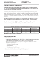
Above based on angular acceleration of 100 RAD/SEC2
Determining Shaft Type
1. Solid or tubular?
a. In applications requiring more than 1000 R.P.M. or where the application necessitates
a highly balanced auxiliary power shaft, a tubular shaft should be used.
b. Spicer® solid shafting auxiliary power joints are designed for 1000 or less R.P.M.
intermittent service such as:
Driving small hydraulic pumps
Driving winches
Driving low speed product pumps
2. Joint series should be determined using the following chart.
26
Parker Hannifin Corporation
Chelsea Products Division
Olive Branch, MS 38654 USA
Owner’s Manual
6 and 8 Bolt P.T.O.s
Bulletin HY25-1135-M1/US
Installation Instructions
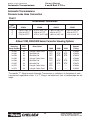
Spicer® Universal Joint Engineering Data Quick Reference Chart
JOINT SERIES
1000
1100
1280
1310
50
54
95
130
TUBING
Diameter
Wall Thickness
W = WELDED S = SEAMLESS
1.750
.065
W
1.250
.095
S
2.500
.083
W
3.00
.083
W
FLANGE DIAMETER (Swing Diameter)
Rectangular Type
3.500
3.500
3.875
3.875
BOLT HOLES - Flange Yoke
Circle
Diameter
Number
Male Pilot Dia.
2.750
.312
4
2.250
2.750
.312
4
2.250
3.125
.375
4
2.375
3.125
.375
4
2.375
2.188
2.656
3.469
3.469
.938
.938
1.062
1.062
TORQUE RATING
Automotive (Gas or Diesel Engine) lbs. ft.
Continuous
DISTANCE ACROSS LUGS
Snap Ring
Construction
BEARING DIAMETER
MAXIMUM OPERATING SPEED * BY TUBE SIZE, SOLID SHAFT SIZE, AND LENGTH
*(For speed below 500 R.P.M. or over 2500 R.P.M., contact your Chelsea Distributor)
Tubing Dia. &
Wall Thickness
Joint & Shaft
(W=Welded
S=Seamless)
MAX. INSTALLED LENGTH IN INCHES FOR GIVEN R.P.M.
Centerline to Centerline of Joints For a Two Joint Assembly or
Centerline of Joint to Centerline of Center Bearing For a Joint & Shaft
R.P.M. - Revolutions per Minute
500
1000
1500
2000
2500
1.750" X .065" W
117"
82"
67"
58"
52"
1.250" X .095" S
91"
64"
52"
45"
40"
2.500" X .083" W
122"
87"
70"
62"
55"
3.000" X .083" W
-
-
-
85"
76"
.750"
60"
42"
35"
30"
27"
.812"
62"
44"
36"
31"
28"
.875"
65"
46"
37"
32"
29"
1.000"
69"
49"
40"
35"
31"
1.250"
77"
55"
45"
39"
35"
SOLID SHAFT
Diameter
27
Parker Hannifin Corporation
Chelsea Products Division
Olive Branch, MS 38654 USA
Owner’s Manual
6 and 8 Bolt P.T.O.s
Bulletin HY25-1135-M1/US
Continuity Check
Continuity Check
379639 and 379652 Indicator Switches
In order to insure that the switch is functioning
properly, the following procedure can be used
with the unit on a bench, or installed.
1. Use a continuity checker, battery type,
either meter or light. Attach one (1)
probe to the screw on the 379639 or
379652 Indicator Switch.
Note: Make sure 379639 and 379652
Indicator Switches in the P.T.O. shifter
or housing are torqued to 10-15 lbs. ft.
(1.38-2.07 kg meters).
Fig. 23
2. With the other probe, make contact with
the shifter cover or housing (Fig. 23).
3. Actuate shifting device and the meter or
light* should be actuated when P.T.O.
gear is engaged (Fig. 24).
4. Shift unit out of gear and the meter or
light* should return to normal as shown.
Fig. 24
This test procedure can be used to check
Chelsea wire, lever, and air shifter covers,
although an air source would be necessary for
the latter.
* If a meter is not available the light in the
328751-1X can be used. A six volt battery is all
that is necessary for a power source.
CAUTION: Indicator switches are capable of 0.5 amps maximum.
28
Parker Hannifin Corporation
Chelsea Products Division
Olive Branch, MS 38654 USA
Owner’s Manual
6 and 8 Bolt P.T.O.s
Bulletin HY25-1135-M1/US
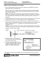
Cable Control Installation
Cable Control Installation Instructions *
1. Find a suitable area on the dash to install the cable control (328346-10X) and the
control plate (68-P-18) indicator light.
Optional Location: As an option the control cable and knob can be located through
floor. Using this option the control plate and indicator light should still be located on
dash, in close proximity.
NOTE: The location of the cable control and the control plate should be as close to
each other as possible and easily accessible by the driver or operator, but should not
be an obstacle to driver movement nor interfere with other controls, instruments, or
equipment.
2. CAUTION: Before drilling any holes, make sure there is adequate room on both sides
through dash wall, drill a 1/2" (.5") diameter hole for the control cable. [1]
3. Install the control cable on the dash using the hex nuts supplied with the cable. The
knob can then be screwed into place [2]. The length of cable can then run through the
firewall and back to the P.T.O. —making sure it is kept away from the exhaust,
moving parts, etc.
NOTE: Do not kink the cable. In order for the cable to operate properly, there can be
no bends smaller than 6 inch radius. Total bends in the cable should not exceed 360°
(example - four 90° bends in cable).
4. Using the template found on page 45
(SK-168) drill the necessary holes for the
control plate-indicator light.
5. Install the control plate (68-P-18) stick
on decal and indicator light on the dash
using the hardware supplied in the
328751-1X installation kit (Fig. 25).
Fig. 25
* All six bolt wire shifts with the exception of the reversible, dual shift units, and some
gear boxes.
29
Parker Hannifin Corporation
Chelsea Products Division
Olive Branch, MS 38654 USA
Bulletin HY25-1135-M1/US
Cable Control Installation
Owner’s Manual
6 and 8 Bolt P.T.O.s
Cable Control Installation Instructions * (Continued)
6. Determine from which direction the cable must come in order for the unit to be
disengaged when the knob is all the way in.
NOTE: The shifter must always be installed in the following manner:
* CABLE IN: P.T.O. DISENGAGED(6A): OUT OF GEAR POSITION
CABLE OUT: P.T.O. ENGAGED(6B): IN GEAR POSITION
* The wire shift cable should be installed so that when the cable (knob) is
shifter, to the disengaged mode.
7. Install the wire control bracket found in either the 328380X or 328380-1X wire control
parts bag. [7]
8. Line the cable up with the wire control bracket and shifter lever (disengaged position)
on the P.T.O. cover assembly [8]
NOTE: It may be necessary to change the position of the shifter lever on the P.T.O.
To do this, remove the shifter cover from the unit. This will prevent the possible loss
of the poppet and/or spring into the transmission if the shifter post assembly should
be pushed through the cover when reinstalling the lever.
9. Shift the P.T.O. to the engaged position to see how much of the cable casing must be
cut to allow the lever enough travel to shift in and out completely. The casing need
only go just beyond the bracket, whereas, the wire must be long enough to go
through the swivel pin in the shifter lever. [9]
NOTE: In some instances the cable control may not be long enough. Chelsea has
available four longer lengths than the standard ten-foot cable. These come in five foot
increments (i.e., 328346-15X = 15-foot cable).
10. When the length of the casing has been determined, pull the wire back through until
the case can be cut without cutting the wire. Use a hacksaw or heavy pair of side
cutters to cut the casing.
NOTE: The cable can be held by a bench vise as long as the jaws are not tightened
to the point where the case mushrooms. If a vise is not accessible, a pair of vise grips
will do the job.
* All six bolt wire shifts with the exception of the reversible, dual shift units, and some
gear boxes.
30
Parker Hannifin Corporation
Chelsea Products Division
Olive Branch, MS 38654 USA
Bulletin HY25-1135-M1/US
Cable Control Installation
Owner’s Manual
6 and 8 Bolt P.T.O.s
Cable Control Installation Instructions * (Continued)
11. Push the wire back through and install the cable using the hardware from the
previously mentioned wire control parts bag (328380X).
12. Cut the excess wire after the cable casing and wire have been installed and tightened.
* All six bolt wire shifts with the exception of the reversible, dual shift units, and some
gear boxes.
31
Parker Hannifin Corporation
Chelsea Products Division
Olive Branch, MS 38654 USA
Bulletin HY25-1135-M1/US
Cable Control Installation
Owner’s Manual
6 and 8 Bolt P.T.O.s
Cable Control Installation Instructions * (Continued)
Indicator Light Installation
Sketch (SK-286 Rev G)
CAUTION: Indicator switches are capable of 0.5 amps maximum.
NOTE: All wires and cables must be clear of heat source and moving parts.
13. Shift the P.T.O. to insure enough casing has been removed to allow full gear engagement.
14. Install the wiring for the indicator light using the schematic above (SK-286 Rev. G).
NOTE: Check both the cable and indicator light wires to be certain that they are not
near the exhaust system or any moving parts. Carefully fasten to stationary parts of the
vehicle if necessary.
15. Shift the P.T.O. The following should be adhered to:
15A. CABLE IN: P.T.O. DISENGAGED: LIGHT OUT
15B. CABLE OUT: P.T.O. ENGAGED: LIGHT ON
NOTE: The P.T.O. should be checked for continuity as per the instructions in
this manual.
NOTE: Cable must be rigidly mounted-possibly to the transmission within 12-24"
of the P.T.O.
* All six bolt wire shifts with the exception of the reversible, dual shift units, and some
gear boxes.
32
Parker Hannifin Corporation
Chelsea Products Division
Olive Branch, MS 38654 USA
Bulletin HY25-1135-M1/US
Cable Control Installation
Owner’s Manual
6 and 8 Bolt P.T.O.s
Cable Control Installation Instructions (Continued)
(Reversibles, dual shift units, and some gear boxes)
1. Use steps #1-#5 from previous
instructions.
2. In step #6 the cable can come from
either direction since the P.T.O. will
always be engaged when all the way
in or out.
3. Follow step #7 and #8.
4. In step #9 shift the P.T.O. from
forward to reverse or vice versa to
determine the amount of travel
needed and the length of casing to
be cut.
5. Follow step #10-#14.
6. Step #15 will show the folding:
CABLE IN: P.T.O. ENGAGED: LIGHT ON
CABLE OUT (1st position):
P.T.O. DISENGAGED: LIGHT OUT
CABLE OUT (2nd position):
P.T.O. ENGAGED: LIGHT ON
33
Parker Hannifin Corporation
Chelsea Products Division
Olive Branch, MS 38654 USA
Owner’s Manual
6 and 8 Bolt P.T.O.s
Bulletin HY25-1135-M1/US
Automatic Transmissions
Automatic Transmissions
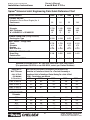
Pressure Lube Hose Connection
Chart I
Dimensional Information
TEE
FITTING
378840
D
E
F
378880
.750-16 U.N.F. 2A
.250-18 N.P.T.F.
.750-16 N.P.T.F.
.875-14 U.N.F. 2A
.250-18 N.P.T.F.
.875-14 U.N.F. 2NB
378970
378897
1.062-12 U.N.F. 2A
.250-18 N.P.T.F.
1.062-12 U.N.F. 2B
1.312-12 U.N. 2A
.250-18 N.P.T.F.
1.312-12 U.N. 2B
Allison 1000, 2000/2400 Series Converter Housing Options
Converter
Housing
SAE
Group Number Number
34-561
34-562
34-563
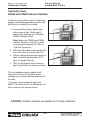
34-565
34-566
34-567
34-572
34-573
#3
#2
#3
#3
#2
#2
#3
#3
Description
Integral Cooler
Manifold Pad
Manifold Pad
Integral Cooler
Manifold Pad
Manifold Pad
Integral Cooler
Integral Cooler
Ports
Ports
Ports
Ports
1000
2000
2400
Chelsea
Fitting
STD.
OPT.
OPT.
STD.
OPT.
OPT.
STD.
STD.
—STD.
STD.
—STD.
STD.
——-
—STD.
STD.
—STD.
STD.
——-
378840
378970
378970
378840
378970
378970
378840
378840
The specific “T” fitting for each Automatic Transmission is called out at the bottom of each
transmission’s application sheet. If a “T” fitting is not called out, then a standard pipe tee will
adapt.
34
Parker Hannifin Corporation
Chelsea Products Division
Olive Branch, MS 38654 USA
Bulletin HY25-1135-M1/US
Automatic Transmissions
Owner’s Manual
6 and 8 Bolt P.T.O.s
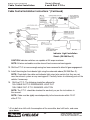
442 Series Pressure Lube for Allison 1000, 2000/2400 Series
(SK-382 Rev B)
442 Series
See Chart page 31
379896 (442*FHVP)
379594 (442*BHVP)
Pipe Adapter
500841-1
90O Elbow Pipe
328075X Hose Assembly
35
Parker Hannifin Corporation
Chelsea Products Division
Olive Branch, MS 38654 USA
Owner’s Manual
6 and 8 Bolt P.T.O.s
Bulletin HY25-1135-M1/US
Automatic Transmissions
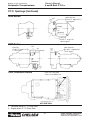
P.T.O. Openings for Automatic Transmissions Allison Models
HT-740
HT-750D
78T
T Fitting 378897
5.6
[142.24mm]
Lube Tap
1 5/16 O-Ring 35-45 P.S.I.
2.4-3.2 Kg/cm2
MAIN PRESSURE
1/8 N.P.T. 90-175 P.S.I.
6.3-12.2 Kg/cm2
3.5
[88.9mm]
CLT-750
40T
78T
5.6
142.24mm
T Fitting 378897
Lube Tap
1 5/16 O-Ring 35-45 P.S.I.
2.4-3.2 Kg/cm2
64T
MAIN PRESSURE
1/8 N.P.T. 90-270 P.S.I.
6.3-19 Kg/cm2
3.5
[88.9mm]
HT-70
40T
78T
78T
8.46
214.8mm
6.7
[170.18mm]
Lube Tap
1/8 N.P.T. 5-15 P.S.I.
.35-1.05 Kg/cm2
2.00
[50.8mm]
6.2
[157.48mm]
MAIN PRESSURE
1/8 N.P.T. 90-240 P.S.I.
7.7-16.8 Kg/cm2
1. Converter driven P.T.O. Drive Gear.
2. Engine driven P.T.O. Drive Gear.
36
Parker Hannifin Corporation
Chelsea Products Division
Olive Branch, MS 38654 USA
Owner’s Manual
6 and 8 Bolt P.T.O.s
Bulletin HY25-1135-M1/US
Automatic Transmissions
P.T.O. Openings (Continued)
5000 Series
Main Pressure
1/4 N.P.T. 100-215 P.S.I.
7-14.4 Kg/cm2
38 T
.6
[15.24mm]
1.6
[40.64mm]
Lube Tap
1/4 N.P.T. 15-35 P.S.I.
1.05-2.4 Kg/cm2
46 T
8000 Series
Lube Tap
3/8 N.P.T. 16-60 P.S.I.
1.1-4.2 Kg/cm2
43 T
Main Pressure
1/4 N.P.T. 140-230 P.S.I.
9.9-15 Kg/cm2
8.6
[218.44mm]
38T
7.9
[300.66mm]
52 T
1000, 2000/2400 Series
Install Tee Fitting Here
“From” Cooler Return Port
1. Converter driven P.T.O. Drive Gear.
2. Engine driven P.T.O. Drive Gear.
37
Parker Hannifin Corporation
Chelsea Products Division
Olive Branch, MS 38654 USA
Owner’s Manual
6 and 8 Bolt P.T.O.s
Bulletin HY25-1135-M1/US
Automatic Transmissions
P.T.O. Openings (Continued)
MT-30-42 (57 Teeth)
6 Speed
5.1
Lube Tap
3/8 N.P.T.12-20 P.S.I.
.92-1.4 Kg/cm2
Main Pressure
1/8 N.P.T. 90-200 P.S.I.
6.3-14 Kg/cm2
11.9
[302.26mm]
3341 - 3441 (55 Teeth)
AT-540
Lube Tap
3/4 O-Ring 50-70 P.S.I.
3.5-4.9 Kg/cm2
T Fitting 378840
4.7
Main Pressure
1/8 N.P.T. 90-150 P.S.I.
6.3-10.5 Kg/cm2
11.9
[302.26mm]
4 Speed (64 Teeth)
MT-640
T Fitting 378880
Lube Tap
Before Nov. 1974
Use T Fitting 378880
7/8" O-Ring 25-30 P.S.I.
1.75-2.1 Kg/cm2
After Nov. 1974
Use T Fitting 378970
1-1/16" O-Ring 25-30 P.S.I.
1.75-2.1 Kg/cm2
5.6
[142.24mm]
6.4
[162.16mm]
13
[330.2mm]
13.5
[342.9mm]
Main Pressure
1/8 N.P.T. 125-217 P.S.I.
8.7-15.2 Kg/cm2
1. Converter driven P.T.O. Drive Gear.
38
Parker Hannifin Corporation
Chelsea Products Division
Olive Branch, MS 38654 USA
Bulletin HY25-1135-M1/US
P.T.O. Shifting Procedure
Owner’s Manual
6 and 8 Bolt P.T.O.s
P.T.O. Shifting Procedure & Precautions
This vehicle is equipped with a POWER TAKE-OFF
Shut Engine Off Before Working On Power Take-Off Or Getting Below Vehicle.
Consult Operating Instructions Before Using. (See Sun Visor)
POWER TAKE-OFF OPERATION VEHICLE STATIONARY
I. Manual Transmission
1. A Power Take-Off is, and should be, operated as an integral part of the
main transmission.
2. Before shifting the Power Take-Off into or out of gear disengage the
clutch and wait for transmission or P.T.O. gears to stop rotating.
II. Automatic Transmission with Manual Shift P.T.O. (Includes Air Shift)
On automatic transmissions, the gears in the transmission turn when the
transmission is in neutral, therefore, gear clashing will occur if the power
take-off is shifted into gear at this time.
A. With Converter Driven Gear:
1. Shift transmission lever into any of the drive positions (this will stop
transmission gear from turning).
2. Shift Power Take-Off into gear.
3. Shift transmission into neutral (this will start gears turning).
B. With Engine Driven Gear:
1. Shift P.T.O. into gear before starting engine. This procedure should
eliminate gear clash.
III. Automatic Transmission with Powershift P.T.O.
Engage P.T.O. with engine at idle speed.
Power Shift P.T.O.s: Engine must be at idle when P.T.O. is engaged.
See transmission manufacturer’s instructions for special procedures.
IMPORTANT: Failure to follow proper shifting or operating
sequences will result in premature P.T.O. failure with possible
damage to other equipment.
WARNING
Use only wire control with P.T.O. made for wire cable control. If lever control is desired,
order P.T.O. for lever control. The internal shifting mechanism for wire is not designed for
heavy forces usually encountered with lever control linkage.
Do not attempt to work on an installed Power Take-Off with the engine running.
Make sure to block any moving or raised device that may injure a person working on or
under the truck. A lever or its linkage may be accidentally moved causing movement of the
device which could cause injury to a person near the device.
39
Parker Hannifin Corporation
Chelsea Products Division
Olive Branch, MS 38654 USA
40
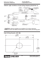
Note: Template for control plate on page 46.
Note: Tube nut is reusable as long as nylon tubing is not removed from the tube nut.
Caution: When installing nylon tubing avoid sharp angles, exhaust and manifold systems.
Installation Sketches
Warning: Connect directly to air supply.
Do not use tubing between air supply and pressure protection valve.
Bulletin HY25-1135-M1/US
Owner’s Manual
6 and 8 Bolt P.T.O.s
Air Shift Installation Sketch for 340 and 352 Series Using:
Williams Valve (SK-228 Rev G)
Parker Hannifin Corporation
Chelsea Products Division
Olive Branch, MS 38654 USA
Bulletin HY25-1135-M1/US
Installation Sketches
Owner’s Manual
6 and 8 Bolt P.T.O.s
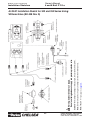
Air Shift Installation Sketch for 880 and 823 Series Using:
Williams Valve (SK-276 Rev H)
328388-61X Installation Kit
Warning: Connect directly to the air supply. Do not use tubing
between the air supply and the pressure protection valve.
Caution: When installing nylon tubing avoid sharp angles, exhaust and manifold systems.
Important: When this installation is used on vehicles with automatic transmissions, the P.T.O.
drive gear must be stopped before shifting.
NOTE: Tube nut is reusable as long as nylon tubing is not removed from the tube nut.
NOTE: The template for the control plate is on page 46.
41
Parker Hannifin Corporation
Chelsea Products Division
Olive Branch, MS 38654 USA
42
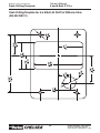
Caution: When installing nylon tubing avoid sharp angles, exhaust and manifold systems.
Important: When this installation is used on vehicles with automatic transmissions the P.T.O. drive gear must be stopped before shifting.
Note: Tube nut is reusable as long as nylon tubing is not removed from the tube nut.
Note: Template for control plate on page 46.
Warning: Connect directly to air supply.
Do not use tubing between air supply and pressure protection valve.
Installation Sketches
Note: Connect plastic tubing to the
push connect (Air Shift Cover Ass'y).
Bulletin HY25-1135-M1/US
Owner’s Manual
6 and 8 Bolt P.T.O.s
Air Shift Installation Sketch for 100, 221, 260, 429, 434, 435, 436, 437,
438, 442, 447, 489, 660, 680 and 812 Series Using:
Williams Valve (SK-231 Rev D)
Parker Hannifin Corporation
Chelsea Products Division
Olive Branch, MS 38654 USA
43
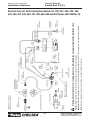
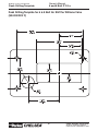
Caution: When installing nylon tubing avoid sharp angles, exhaust and manifold systems.
Important: When this installation is used on vehicles with automatic transmissions the P.T.O. drive gear must be stopped before shifting.
Note: Tube nut is reusable as long as nylon tubing is not removed from the tube nut.
Warning: Connect directly to air supply. Do not use tubing between air supply and pressure protection valve.
379336
Switch
Bracket
Installation Sketches
Note: Connect plastic tubing to the
push connect (Air Shift Cover Ass'y).
328388-47X - 12v Installation Kit
328388-48X - 24v Installation Kit
Bulletin HY25-1135-M1/US
Owner’s Manual
6 and 8 Bolt P.T.O.s
Electric Over Air Shift Installation Sketch for 100, 221, 260, 429, 434,
435, 436, 437, 438, 442, 447, 489, 660, 680 and 812 Series (SK-238 Rev H)
Parker Hannifin Corporation
Chelsea Products Division
Olive Branch, MS 38654 USA
Owner’s Manual
6 and 8 Bolt P.T.O.s
Bulletin HY25-1135-M1/US
Installation Sketches
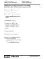
Installing Rotatable Flanges
The rotatable flange is shipped loose with the P.T.O. units for ease of installation. After
determining the flange position, attach the flange to the P.T.O. bearing cap using the
capscrews provided in the bag kit. Bag kit number 328170-207X (6-bolt family) will contain
(3) capscrews (378447-6) and 328170-208X (277 Series) will contain (4) capscrews for
attaching the flange to the P.T.O. bearing cap.
After installing the capscrews make sure to torque the screws to 16-20 lbs. ft.
▼
Consideration should be taken on the size and weight of the pump being installed. (see
pages 4 and 5)
▼
▼
RB Flange Shown
NOTE: Reinstalling or tightening of a rotatable flange after it has become loose is not
recommended. If a P.T.O. has run for length of time after the flange has become loose,
the flange and / or bearing cap may not be to manufacturing tolerance.
44
Parker Hannifin Corporation
Chelsea Products Division
Olive Branch, MS 38654 USA
Bulletin HY25-1135-M1/US
Installation Sketches
Owner’s Manual
6 and 8 Bolt P.T.O.s
Indicator Light Installation & Dash Drilling Template (SK-286 Rev G)
CAUTION: Indicator switches are capable of 0.5 amps maximum.
NOTE: All wires and cables must be clear of heat source and moving parts.
Dash Drilling Template (SK-168)
45
Parker Hannifin Corporation
Chelsea Products Division
Olive Branch, MS 38654 USA
Bulletin HY25-1135-M1/US
Dash Drilling Template
Owner’s Manual
6 and 8 Bolt P.T.O.s
Dash Drilling Template for 6 & 8 Bolt Air Shift for Williams Valve
(SK-204 REV C)
46
Parker Hannifin Corporation
Chelsea Products Division
Olive Branch, MS 38654 USA
Bulletin HY25-1135-M1/US
Dash Drilling Template
Owner’s Manual
6 and 8 Bolt P.T.O.s
Dash Drilling Template for 6 & 8 Bolt Air Shift for Williams Valve
(SK-204 REV C)
47
Parker Hannifin Corporation
Chelsea Products Division
Olive Branch, MS 38654 USA
Bulletin HY25-1135-M1/US
Power Take-Off Maintenance
Owner’s Manual
6 and 8 Bolt P.T.O.s
Power Take-Off Maintenance
Due to the normal and sometime severe torsional vibrations that Power Take-Off units
experience, operators should follow a set maintenance schedule for inspections. Failure
to service loose bolts or Power Take-Off leaks could result in potential auxiliary Power-TakeOff or transmission damage.
Periodic P.T.O. MAINTENANCE is required by the owner/operator to ensure proper, safe
and trouble free operation.
Daily:
Check all air, hydraulic and working mechanisms before operating
P.T.O. Perform maintenance as required.
Monthly: Inspect for possible leaks and tighten all air, hydraulic and
mounting hardware, if necessary. Torque all bolts, nuts, etc. to
Chelsea specifications. Insure that splines are properly
lubricated, if applicable. Perform maintenance as required.
With regards to the direct mounted pump splines, the P.T.O. requires the application of a
specially formulated anti-fretting, high pressure, high temperature grease. The addition
of the grease has been proven to reduce the effects of the torsional vibrations, which
result in fretting corrosion on the P.T.O. internal splines as well as the pump external
splines. Fretting corrosion appears as a “rusting and wearing” of the pump shaft splines.
Severe duty applications, which require long P.T.O. running times and high torque may
require more frequent regreasing. Applications such as Utility Trucks that run continuously and are lightly loaded also require frequent regreasing due to the sheer hours of
running time. It is important to note that service intervals will vary for each and every
application and is the responsibility of the end user of the product. Chelsea also
recommends that you consult your pump owners manuals and technical services for
their maintenance guidelines. Fretting corrosion is caused by many factors and without
proper maintenance; the anti-fretting grease can only reduce its effects on components.
Chelsea offers the grease to our customers in two packages. The first is a 5/8 fluid ounce
tube (379688), which is included with every applicable P.T.O., and the second is a 14ounce grease cartridge (379831). Chelsea also offers greaseable shafts for most all
output designators.
Warranty: Failure to comply entirely with the provisions set forth in the appropriate
Owner’s Manual will result in voiding of ALL Warranty consideration.
48
Parker Hannifin Corporation
Chelsea Products Division
Olive Branch, MS 38654 USA
Notes
49
Parker Hannifin Corporation
Chelsea Products Division
Olive Branch, MS 38654 USA
Notes
50
Parker Hannifin Corporation
Chelsea Products Division
Olive Branch, MS 38654 USA
Notes
51
Parker Hannifin Corporation
Chelsea Products Division
Olive Branch, MS 38654 USA
Offer of Sale
The items described in this document and other documents or descriptions provided by Parker Hannifin Corporation, its subsidiaries and
its authorized distributors are hereby offered for sale at prices to be established by Parker Hannifin Corporation, its subsidiaries and its
authorized distributors. This offer and its acceptance by any customer ("Buyer") shall be governed by all of the following Terms and
Conditions. Buyer’s order for any such items, when communicated to Parker Hannifin Corporation, its subsidiary or an authorized
distributor ("Seller") verbally or in writing, shall constitute acceptance of this offer.
1. Terms and Conditions of Sale: All descriptions, quotations,
proposals, offers, acknowledgments, acceptances and sales of
Seller’s products are subject to and shall be governed exclusively
by the terms and conditions stated herein. Buyer’s acceptance of
any offer to sell is limited to these terms and conditions. Any terms
or conditions in addition to, or inconsistent with those stated
herein, proposed by Buyer in any acceptance of an offer by Seller,
are hereby objected to. No such additional, different or inconsistent
terms and conditions shall become part of the contract between
Buyer and Seller unless expressly accepted in writing by Seller.
Seller’s acceptance of any offer to purchase by Buyer is expressly
conditional upon Buyer’s assent to all the terms and conditions
stated herein, including any terms in addition to, or inconsistent
with those contained in Buyer’s offer, Acceptance of Seller’s
products shall in all events constitute such assent.
2. Payment: Payment shall be made by Buyer net 30 days from the
date of delivery of the items purchased hereunder. Amounts not
timely paid shall bear interest at the maximum rate permitted by law
for each month or portion thereof that the Buyer is late in making
payment. Any claims by Buyer for omissions or shortages in a
shipment shall be waived unless Seller receives notice thereof
within 30 days after Buyer’s receipt of the shipment.
3. Delivery: Unless otherwise provided on the face hereof, delivery
shall be made F.O.B. Seller’s plant. Regardless of the method of
delivery, however, risk of loss shall pass to Buyer upon Seller’s
delivery to a carrier. Any delivery dates shown are approximate
only and Seller shall have no liability for any delays in delivery.
4. Warranty: Seller warrants that the items sold hereunder shall be
free from defects in material or workmanship for a period of:
(A) All Power Take-Off units one (1) year from date of installation.
(B) Except 267, 277, 278, 242, 244, 246, 250, 251 and 859 series
two (2) years from date of installation.
THIS WARRANTY COMPRISES THE SOLE AND ENTIRE WARRANTY PERTAINING TO ITEMS PROVIDED HEREUNDER. SELLER
MAKES NO OTHER WARRANTY, GUARANTEE, OR REPRESENTATION OF ANY KIND WHATSOEVER. ALL OTHER WARRANTIES, INCLUDING BUT NOT LIMITED TO, MERCHANTABILITY
AND FITNESS FOR PURPOSE, WHETHER EXPRESS, IMPLIED,
OR ARISING BY OPERATION OF LAW, TRADE USAGE, OR
COURSE OF DEALING ARE HEREBY DISCLAIMED. NOTWITHSTANDING THE FOREGOING, THERE ARE NO WARRANTIES
WHATSOEVER ON ITEMS BUILT OR ACQUIRED WHOLLY OR
PARTIALLY, TO BUYER’S DESIGNS OR SPECIFICATIONS.
5. Limitation Of Remedy: SELLER’S LIABILITY ARISING FROM
OR IN ANY WAY CONNECTED WITH THE ITEMS SOLD OR THIS
CONTRACT SHALL BE LIMITED EXCLUSIVELY TO REPAIR OR
REPLACEMENT OF THE ITEMS SOLD OR REFUND OF THE
PURCHASE PRICE PAID BY BUYER, AT SELLER’S SOLE OPTION. IN NO EVENT SHALL SELLER BE LIABLE FOR ANY
INCIDENTAL, CONSEQUENTIAL OR SPECIAL DAMAGES OF
ANY KIND OR NATURE WHATSOEVER, INCLUDING BUT NOT
LIMITED TO LOST PROFITS ARISING FROM OR IN ANY WAY
CONNECTED WITH THIS AGREEMENT OR ITEMS SOLD HEREUNDER, WHETHER ALLEGED TO ARISE FROM BREACH OF
CONTRACT, EXPRESS OR IMPLIED WARRANTY, OR IN TORT,
INCLUDING WITHOUT LIMITATION, NEGLIGENCE, FAILURE TO
WARN OR STRICT LIABILITY.
6. Changes, Reschedules and Cancellations: Buyer may request
to modify the designs or specifications for the items sold hereunder
as well as the quantities and delivery dates thereof, or may request
to cancel all or part of this order, however, no such requested
modification or cancellation shall become part of the contract
between Buyer and Seller unless accepted by Seller in a written
amendment to this Agreement. Acceptance of any such requested
modification or cancellation shall be at Seller’s discretion, and
shall be upon such terms and conditions as Seller may require.
7. Special Tooling: A tooling charge may be imposed for any
special tooling, including without limitation, dies, fixtures, molds
and patterns, acquired to manufacture items sold pursuant to this
contract. Such special tooling shall be and remain Seller’s property notwithstanding payment of any charges by Buyer. In no event
will Buyer acquire any interest in apparatus belonging to Seller
which is utilized in the manufacture of the items sold hereunder,
even if such apparatus has been specially converted or adapted for
such manufacture and notwithstanding any charges paid by Buyer.
Unless otherwise agreed, Seller shall have the right to alter,
discard or otherwise dispose of any special tooling or other
property in its sole discretion at any time.
8. Buyer’s Property: Any designs, tools, patterns, materials,
drawings, confidential information or equipment furnished by
Buyer or any other items which become Buyer’s property, may be
considered obsolete and may be destroyed by Seller after two (2)
consecutive years have elapsed without Buyer placing an order
for the items which are manufactured using such property, Seller
shall not be responsible for any loss or damage to such property
while it is in Seller’s possession or control.
9. Taxes: Unless otherwise indicated on the face hereof, all
prices and charges are exclusive of excise, sales, use, property,
occupational or like taxes which may be imposed by any taxing
authority upon the manufacture, sale or delivery of the items sold
hereunder. If any such taxes must be paid by Seller or if Seller is
liable for the collection of such tax, the amount thereof shall be
in addition to the amounts for the items sold. Buyer agrees to pay
all such taxes or to reimburse Seller therefore upon receipt of its
invoice. If Buyer claims exemption from any sales, use or other
tax imposed by any taxing authority, Buyer shall save Seller
harmless from and against any such tax, together with any
interest or penalties thereon which may be assessed if the items
are held to be taxable.
10. Indemnity For Infringement of Intellectual Property Rights:
Seller shall have no liability for infringement of any patents,
trademarks, copyrights, trade dress, trade secrets or similar
rights except as provided in this Part 10. Seller will defend and
indemnify Buyer against allegations of infringement of U.S.
Patents, U.S. Trademarks, copyrights, trade dress and trade
secrets (hereinafter ‘Intellectual Property Rights’). Seller will
defend at its expense and will pay the cost of any settlement or
damages awarded in an action brought against Buyer based on
an allegation that an item sold pursuant to this contract infringes
the Intellectual Property Rights of a third party. Seller’s obligation to defend and indemnify Buyer is contingent on Buyer
notifying Seller within ten (10) days after Buyer becomes aware
of such allegations of infringement, and Seller having sole
control over the defense of any allegations or actions including
all negotiations for settlement or compromise. If an item sold
hereunder is subject to a claim that it infringes the Intellectual
Property Rights of a third party, Seller may, at its sole expense
and option, procure for Buyer the right to continue using said
item, replace or modify said item so as to make it noninfringing,
or offer to accept return of said item and return the purchase price
less a reasonable allowance for depreciation. Notwithstanding
the foregoing, Seller shall have no liability for claims of infringement based on information provided by Buyer, or directed to
items delivered hereunder for which the designs are specified in
whole or part by Buyer, or infringements resulting from the
modification, combination or use in a system of any item sold
hereunder. The foregoing provisions of this Part 10 shall constitute Seller’s sole and exclusive liability and Buyer’s sole and
exclusive remedy for infringement of Intellectual Property Rights.
If a claim is based on information provided by Buyer or if the
design for an item delivered hereunder is specified in whole or in
part by Buyer, Buyer shall defend and indemnify Seller for all
costs, expenses or judgments resulting from any claim that such
item infringes any patent, trademark, copyright, trade dress, trade
secret or any similar right.
11. Force Majeure: Seller does not assume the risk of and shall
not be liable for delay or failure to perform any of Seller’s
obligations by reason of circumstances beyond the reasonable
control of Seller (hereinafter ‘Events of Force Majeure’). Events
of Force Majeure shall include without limitation, accidents, acts
of God, strikes or labor disputes, acts, laws, rules or regulations
of any government or government agency, fires, floods, delays or
failures in delivery of carriers or suppliers, shortages of materials
and any other cause beyond Seller’s control.
12. Entire Agreement/Governing Law: The terms and conditions
set forth herein, together with any amendments, modifications
and any different terms or conditions expressly accepted by
Seller in writing, shall constitute the entire Agreement concerning the items sold, and there are no oral or other representations
or agreements which pertain there/to. This Agreement shall be
governed in all respects by the law of the State of Ohio. No
actions arising out of the sale of the items sold hereunder or this
Agreement may be brought by either party more than two (2) years
after the cause of action accrues.
1/06-P
52
Parker Hannifin Corporation
Chelsea Products Division
Olive Branch, MS 38654 USA
Parker Hannifin Corporation
Chelsea Products Division
8225 Hacks Cross Road
Olive Branch, Mississippi 38654 USA
Tel: (662) 895-1011
Fax: (662) 895-1019
www.parker.com/chelsea
FP 01/08 20M