1
Bulletin HY25-1202-M1/US
Owner’s Manual
Split Shaft and
Gear Box
Effective:
January 2005
Supersedes: HY25-1202-M1/US
April 2003
700 Series
712 Series
721 Series
732 Series
741 Series
901 Series
912 Series
931 Series
941 Series
2230 Series
2442 Series
WARNING
FAILURE OR IMPROPER SELECTION OR IMPROPER USE OF THE PRODUCTS AND/OR SYSTEMS DESCRIBED
HEREIN OR RELATED ITEMS CAN CAUSE DEATH, PERSONAL INJURY AND PROPERTY DAMAGE.
This document and other information from Parker Hannifin Corporation, its subsidiaries and authorized distributors
provide product and/or system options for further investigation by users having technical expertise. It is important
that you analyze all aspects of your application and review the information concerning the product or system in the
current product catalog. Due to the variety of operating conditions and applications for these products or systems,
the user, through its own analysis and testing, is solely responsible for making the final selection of the products and
systems and assuring that all performance, safety and warning requirements of the application are met.
The products described herein, including without limitation, product features, specifications, designs, availability and
pricing, are subject to change by Parker Hannifin Corporation and its subsidiaries at any time without notice.
Offer of Sale
The items described in this document are hereby offered for sale by Parker Hannifin Corporation, its subsidiaries or
its authorized distributors. This offer and its acceptance are governed by the provisions stated in the "Offer of Sale".
Patent Information
The Chelsea® Power Take-Off or its components shipped with this owner’s manual may be manufactured under
one or more of the following U.S. patents:
4610175
5228355
4597301
5645363
6151975
6142274
6260682
Other patents pending.
© Copyright 2005, Parker Hannifin Corporation, All Rights Reserved
II
Parker Hannifin Corporation
Chelsea Products Division
Olive Branch, MS 38654 USA
Bulletin HY25-1202-M1/US
Contents
Owner’s Manual
Split Shafts and Gear Box
General Information
Safety Information ..................................................................................................... 1-3
Direct Mount Pump Support Recommendations ..................................................... 4
Shifting Procedures ................................................................................................... 5
Foreword ................................................................................................................... 6
Split Shaft and Gear Box Specifications .................................................................. 8
Horsepower-Torque-R.P.M. Conversion Chart .......................................................... 9
Installation of a Split Shaft
Application Data ........................................................................................................ 10-11
Lubrication Information ............................................................................................. 12
Installation Instructions ............................................................................................. 13
Model 901 Installation Drawings ............................................................................... 14
Model 901 Dimensional Drawings ............................................................................ 15
Model 912 Installation Drawing ................................................................................ 16
Model 912 Dimensional Drawing .............................................................................. 17
Model 931 Installation Drawings ............................................................................... 18
Model 931 Dimensional Drawings ............................................................................ 19
Model 941 Installation Drawing ................................................................................ 20
Model 941 Dimensional Drawing .............................................................................. 21
Installation of a Gear Box
Installation Instructions ............................................................................................. 22
Models 700, 712, 721, 732, 741, 2230 and 2442
Breather Hose Installation .............................................................................................. 23
Installation of a P.T.O. to a Split Shaft
Application Questions ............................................................................................... 24
Mounting Instructions—6 or 8 Bolt Applications ........................................................ 25-26
880/912 Split Shaft Installation ................................................................................. 27
Checking Backlash ........................................................................................................ 28
Wire Shift P.T.O.’s and Gear Boxes
Cable Control Installation Instructions ....................................................................... 29-32
Air Shift Installation Sketch
2442 Gear Box .......................................................................................................... 33
901, 912, and 941 Split Shafts ................................................................................. 34
Air Shift Circuit 2230 Series ..................................................................................... 35
Dash Drilling Templates
2442 Gear Box Air Shift Control .............................................................................. 36
901, 912, and 941 Split Shafts Air Shift Control ...................................................... 37
Wire and Lever Controls .......................................................................................... 38
Indicator Light Installation ......................................................................................... 39
Continuity Check ........................................................................................................... 40
Troubleshooting ............................................................................................................ 41-42
Power Take-Off Maintenance ....................................................................................... 43
Offer of Sale .................................................................................................................... 44
III
Parker Hannifin Corporation
Chelsea Products Division
Olive Branch, MS 38654 USA
Bulletin HY25-1202-M1/US
General Information
Owner’s Manual
Split Shafts and Gear Box
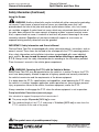
Safety Information
These instructions are for your safety and the safety of the end user. Read them carefully
until you understand them.
General Safety Information
To prevent injury to yourself and/or damage to the equipment:
■
Read carefully all owner’s manuals, service manuals, and/or other instructions.
■
Always follow proper procedures, and use proper tools and safety equipment.
■
Be sure to receive proper training.
■
Never work alone while under a vehicle or while repairing or maintaining equipment.
■
Always use proper components in applications for which they are approved.
■
Be sure to assemble components properly.
■
Never use wornout or damaged components.
■
Always block any raised or moving device that may injure a person working on or under
a vehicle.
■
Never operate the controls of the Power Take-Off or other driven equipment from any
position that could result in getting caught in the moving machinery.
Proper Matching of P.T.O.
WARNING: A Power Take-Off must be properly matched to the vehicle transmission
and to the auxiliary equipment being powered. An improperly matched Power Take-Off
could cause severe damage to the vehicle transmission, the auxiliary driveshaft, and/or to
the auxiliary equipment being powered. Damaged components or equipment could
malfunction causing serious personal injury to the vehicle operator or to others
nearby.
To avoid personal injury and/or equipment damage:
■
Always refer to Chelsea catalogs, literature, and owner’s manuals and follow Chelsea
recommendations when selecting, installing, repairing, or operating a Power Take-Off.
■
Never attempt to use a Power Take-Off not specifically recommended by Chelsea for
the vehicle transmission.
■
Always match the Power Take-Off’s specified output capabilities to the requirements of
the equipment to be powered.
■
Never use a Power Take-Off whose range of speed could exceed the maximum safe
speed of the equipment to be powered.
This symbol warns of possible personal injury.
1
Parker Hannifin Corporation
Chelsea Products Division
Olive Branch, MS 38654 USA
Bulletin HY25-1202-M1/US
General Information
Owner’s Manual
Split Shafts and Gear Box
Safety Information (Continued)
Cold Weather Operation of Powershift P.T.O.s
WARNING: During extreme cold weather operation [32°F (0°C) and lower], a
disengaged Powershift Power Take-Off can momentarily transmit high torque that will
cause unexpected output shaft rotation. This is caused by the high viscosity of the
transmission oil when it is extremely cold. As slippage occurs between the Power Take-Off
clutch plates, the oil will rapidly heat up and the viscous drag will quickly decrease.
The Power Take-Off output shaft rotation could cause unexpected movement of the driven
equipment resulting in serious personal injury, death, or equipment damage.
To avoid personal injury or equipment damage:
■
Driven equipment must have separate controls.
■
The driven equipment must be left in the disengaged position when not in operation.
■
Do not operate the driven equipment until the vehicle is allowed to warm up.
Rotating Auxiliary Driveshafts
WARNING:
■
Rotating auxiliary driveshafts are dangerous. You can snag clothes, skin, hair, hands,
etc. This can cause serious injury or death.
■
Do not go under the vehicle when the engine is running.
■
Do not work on or near an exposed shaft when the engine is running.
■
Shut off the engine before working on the Power Take-Off or driven equipment.
■
Exposed rotating driveshafts must be guarded.
Guarding Auxiliary Driveshafts
WARNING: We strongly recommend that a Power Take-Off and a directly mounted
pump be used to eliminate the auxiliary driveshaft whenever possible. If an auxiliary driveshaft is used and remains exposed after installation, it is the responsibility of the vehicle
designer and P.T.O. installer to install a guard.
This symbol warns of possible personal injury.
2
Parker Hannifin Corporation
Chelsea Products Division
Olive Branch, MS 38654 USA
Bulletin HY25-1202-M1/US
General Information
Owner’s Manual
Split Shafts and Gear Box
Safety Information (Continued)
Using Set Screws
WARNING: Auxiliary driveshafts may be installed with either recessed or protruding
set screws. If you choose a square head set screw, you should be aware that it will
protrude above the hub of the yoke and may be a point where clothes, skin, hair, hands,
etc. could be snagged. A socket head set screw, which may not protrude above the hub of
the yoke, does not permit the same amount of torquing as does a square head set screw.
Also, a square head set screw, if used with a lock wire, will prevent loosening of the screw
caused by vibration. Regardless of the choice made with respect to a set screw, an
exposed rotating auxiliary driveshaft must be guarded.
IMPORTANT: Safety Information and Owner’s Manual
Chelsea Power Take-Offs are packaged with safety information decals, instructions, and an
owner’s manual. These items are located in the envelope with the P.T.O. mounting gaskets.
Also, safety information and installation instructions are packaged with some individual
parts and kits. Be sure to read the owner’s manual before installing or operating the
P. T. O. Always install the safety information decals according to the instructions provided.
Place the owner’s manual in the vehicle glove compartment.
WARNING: Operating the P.T.O. with the Vehicle in Motion
Some Power Take-Offs may be operated when the vehicle is in motion. To do so, the P.T.O.
must have been properly selected to operate at highway speeds and correctly matched to
the vehicle transmission and the requirements of the driven equipment.
If in doubt about the P.T.O.s specifications and capabilities, avoid operating the P.T.O. when
the vehicle is in motion. Improper application and/or operation can cause serious personal
injury or premature failure of the vehicle, the driven equipment, and/or the P.T.O.
Always remember to disengage the P.T.O. when the driven equipment is not in operation.
Pump Installation Precautions (see next page)
Use a bracket to support the pump to the transmission if:
■ The pump weighs 40 pounds [18.14 kg] or more.
■ The combined length of the P.T.O. and pump is 18 inches [45.72 cm] or more from the
P.T.O. centerline to the end of the pump.
This symbol warns of possible personal injury.
3
Parker Hannifin Corporation
Chelsea Products Division
Olive Branch, MS 38654 USA
Bulletin HY25-1202-M1/US
General Information
Owner’s Manual
Split Shafts and Gear Box
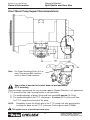
Direct Mount Pump Support Recommendations
Note: For Proper Bracketing Attach At 2 or
more Transmission Bolt Locations
and 2 or More Pump Locations.
Use caution to ensure that bracket does not pre-load pump/
P.T.O. mounting
Chelsea strongly recommends the use of pump supports (Support Brackets) in all applications.
P.T.O. warranty will be void if a pump bracket is not used when:
1) The combined weight of pump, fittings and hose exceed 40 pounds [18.14 kg].
2) The combined length of the P.T.O. and pump is 18 inches [45.72 cm] or more from
the P.T.O. centerline to the end of the pump.
ALSO:
Remember to pack the female pilot of the P.T.O. pump shaft with grease before
installing the pump on the P.T.O. (reference Chelsea grease pack 379688)
This symbol warns of possible personal injury.
4
Parker Hannifin Corporation
Chelsea Products Division
Olive Branch, MS 38654 USA
Bulletin HY25-1202-M1/US
General Information
Owner’s Manual
Split Shafts and Gear Box
Shifting Procedures
Gear Box Operation
P.T.O. mode to road mode:
Vehicle Stationary
Before shifting the gear box into or out of
gear, make sure the gears in the unit and
input shaft have stopped rotating.
1. Disengage the clutch.
2. Shift the split shaft to road mode.
3. Disengage the parking brakes.
4. Resume normal driving procedures.
Split Shaft Operation
Manual Transmission—Vehicle Stationary
Automatic Transmission
Road mode to P.T.O. mode:
Road mode to P.T.O. mode:
1. Disengage the clutch and stop the
vehicle.
1. Stop the vehicle.
2. Engage the parking brakes.
2. Engage the parking brakes.
3. Shift the transmission into Neutral “N.”
3. Shift the split shaft to P.T.O. mode.
4. Shift the split shaft to P.T.O. mode.
4. Select the desired transmission gear as
required.
5. Shift the transmission into the desired
drive range position.
5. Engage the clutch.
6. Apply throttle as required.
6. Apply throttle as required.
P.T.O. mode to road mode:
1. Shift the transmission into Neutral “N.”
2. Shift the split shaft to road mode.
3. Release the parking brake.
4. Resume normal driving procedures.
CAUTION: Inadvertent shift may cause
vehicle movement or unexpected
engagement of P.T.O.
5
Parker Hannifin Corporation
Chelsea Products Division
Olive Branch, MS 38654 USA
Bulletin HY25-1202-M1/US
General Information
Owner’s Manual
Split Shafts and Gear Box
Foreword
Since it is our major objective to show you how to get additional and more profitable
miles from truck, tractor, and trailer components, we want to provide you with information
on the installation of Chelsea Power Take-Offs.
We all realize that an inadequate Split Shaft will overwork any Power Take-Off in a very
short period of time. In addition, a mismatched Split Shaft/P.T.O. combination can result
in unsatisfactory performance of the equipment right from the start.
Before you order new trucks, be sure that you’re getting the right Gear Box, Split Shaft or
P.T.O. combination. This is vital for efficient performance and adequate power. To help you
select the proper type, size, and design of P.T.O., discuss your specific requirements with
a Chelsea P.T.O. specialist. They know their products and have easy access to equipment, transmission, and Power Take-Off manufacturers. They can tell you everything you
need to know about power, at the right time, before you specify components.
Chelsea P.T.O. Safety Label Instructions
1. The two black and orange on white 5" x 7" pressure sensitive vinyl labels, part number
379274; must be placed on the vehicle frame rails (one (1) on each side), in a position
that would be HIGHLY visible to anyone that would go under the truck near the P.T.O.
rotating shaft. If the vehicle is to be painted after these labels are installed, cover them
with two-(2) blank masking covers. Remove the masking covers after painting.
2. Place the one (1) black and orange on white 3.5" x 5" pressure sensitive vinyl label, part
number 379275, on the visor nearest the operator of the vehicle, this must be placed
near the P.T.O. visor label.
3. Place the one (1) red and white with black lettering 3.5" x 7.5" sensitive vinyl label, part
number 379915, on the opposite side of the visor from the above label # 379275.
4. Place the one (1) white and black heavy duty card, part number 379276, in the vehicle
glove box. Again in a position highly visible to the operator, for example: try to place this
card on top of whatever may be in the glove box.
If you require additional labels, please order part number 328946X at no charge from your
local Chelsea Warehouse or send request direct to:
Parker Hannifin Corporation
Chelsea Products Division
8225 Hacks Cross Road
Olive Branch, MS 38654
Customer Service: (662) 895-1011
6
Parker Hannifin Corporation
Chelsea Products Division
Olive Branch, MS 38654 USA
Bulletin HY25-1202-M1/US
General Information
Owner’s Manual
Split Shafts and Gear Box
7
Parker Hannifin Corporation
Chelsea Products Division
Olive Branch, MS 38654 USA
Owner’s Manual
Split Shafts and Gear Box
Bulletin HY25-1202-M1/US
General Information
Split Shaft and Gear Box Specifications
Model No.
700
Single Speed
712 Two
Speed Shaft
721
732
741
2230U
2442F
2442L
2442Q
2442R
2442S
2442U
2442W
2442X
Intermittent
Torque
Horsepower at
Rating
Approximate Lube
500 R.P.M. 1000 R.P.M. P.T.O. Shaft
Weight
Capacity Liters
11.9
10
23.5
20
125 ft. lbs.
110 ft. lbs.
39 lbs.
39 lbs.
1.5 pt.
1.5 pt.
.7
.7
11.9
13.2
13.2
13.2
21.4
23.5
23.5
21.4
21.4
19
18.6
16.7
13.2
23.5
26.5
26.5
26.5
42.8
47
47
42.8
42.8
38
37.2
33.4
26.5
125 ft. lbs.
140 ft. lbs.
140 ft. lbs.
140 ft. lbs.
225 ft. lbs.
250 ft. lbs.
250 ft. lbs.
225 ft. lbs.
225 ft. lbs.
200 ft. lbs.
195 ft. lbs.
175 ft. lbs.
140 ft. lbs.
39 lbs.
49 lbs.
49 lbs.
49 lbs.
88 lbs.
69 lbs.
69 lbs.
69 lbs.
69 lbs.
69 lbs.
69 lbs.
69 lbs.
69 lbs.
901•
500 ft. lbs.
185 lbs.
912•
*
130 lbs.
931•
941•
250 ft. lbs.
**
102 lbs.
60 lbs.
1.5 pt.
.7
1.5 pt.
.7
1.5 pt.
.7
1.5 pt.
.7
1.5 pt.
.7
1.5 pt.
.7
1.5 pt.
.7
1.5 pt.
.7
1.5 pt.
.7
1.5 pt.
.7
1.5 pt.
.7
1.5 pt.
.7
1.5 pt.
.7
2.5 qt.
vertical
2.4
3.0 qt.
horizontal
2.8
2.5 qt. less
P.T.O.
2.4
2.25 qt.
2.175
2.25 pt.
• For allowable split shaft input torque, please consult the chart on page 11.
* The 912 has 3 eight bolt P.T.O. openings on it. For correct P.T.O. applications please
consult your HY25-3000/US catalog.
**The 941 has 2 six bolt P.T.O. openings on it. For correct P.T.O. applications please
consult your HY25-3000/US catalog.
8
Parker Hannifin Corporation
Chelsea Products Division
Olive Branch, MS 38654 USA
Owner’s Manual
Split Shafts and Gear Box
Bulletin HY25-1202-M1/US
General Information
Horsepower-Torque-R.P.M. Conversion Chart
To find the Torque. Given: 100 HP at 1750 R.P.M.
Then: with a straight edge on HP scale at 100 (Left Side) and on R.P.M. scale at 1750.
Find Answer on T scale = 300 foot pounds torque (Middle).
Formula: HP x 5252 = T Foot Pounds Torque
R.P.M.
To find the HP. Given: 3 pounds feet torque at 1750 R.P.M.
Then: with a straight edge on the T scale at 3 (Middle) and on the R.P.M. scale at 1750.
Find Answer on the HP scale = 1 Horsepower (Left Side)
Formula: T x R.P.M. = HP Horsepower
R.P.M.
1000
10
9
8
7
6
500
5
400
4
300
3
250
2.5
200
2
150
1.5
100
1
.9
.8
.7
.6
70
50
.5
40
35
30
.4
.35
25
.25
20
.2
2000
30
100,000
1000
40
50,000
40,000
30,000
500
400
300
20,000
200
10,000
100
50
.1
HP
Horsepower
Scale
60
70
80
90
100
150
5000
4000
3000
50
40
30
2000
20
1000
10
500
400
300
5
4
3
200
2
100
1
50
40
30
.5
.4
.3
20
.2
.3
15
10
200,000
200
300
400
500
600
700
800
900
1000
1500
T
Torque
Foot Pounds Scale
9
2000
3000
R.P.M.
Revolutions
Per Minute Scale
Parker Hannifin Corporation
Chelsea Products Division
Olive Branch, MS 38654 USA
Owner’s Manual
Split Shafts and Gear Box
Bulletin HY25-1202-M1/US
Installation of a Split Shaft
Application Data for Installation of a Split Shaft
Split Shaft Through Torque Ratings
The torque capacity of the Chelsea Split Shaft units is limited by either the engine capacity
or the vehicle wheel skid conditions. To correctly choose a split shaft model for a given
application, the maximum torque from the engine, and the maximum torque due to wheel
conditions, should be calculated. The limiting value obtained by these calculations should
then be compared with the charted split shaft torque capacity.
Formula
Maximum Through Torque From the Engine
1.
Maximum Torque From the Engine = Maximum Net Engine Torque X Manual Transmission Low Gear Ratio X 85% Efficiency
2.
For an automatic transmission, the maximum torque from the engine should be taken
from the engine-transmission performance curve stall torque valve. This information is
generally available from the manufacturer of the automatic transmission.
Maximum Torque Due to Wheel Skid Conditions
3.
Maximum ft. lbs. of Torque = GVW x f x RAD
12 x AR
Where:
GVW
f
RAD
AR
=
=
=
=
maximum gross vehicle weight on the rear wheels only
coefficient of friction
tire loaded rolling radius (inches)
axle ratio
Based on past experience, the coefficients of friction used have been:
f
f
= 0.8 for on-highway service (dry pavement)
= 0.5 for off-highway service
These are generally used values but if information is available for a specific application,
the appropriate coefficient of friction can be used.
10
Parker Hannifin Corporation
Chelsea Products Division
Olive Branch, MS 38654 USA
Owner’s Manual
Split Shafts and Gear Box
Bulletin HY25-1202-M1/US
Installation of a Split Shaft
Application Data for Installation of a Split Shaft
Split Shaft Through Torque Capacity
Maximum Nominal Torque Rating (ft. lbs.)
Diesel Engine
Gas Engine
Split
Shaft
Model
901
Shaft
Outside
Diameter
1 3/4"
Automatic
Transmission
3,300
912
2 3/4"
13,000
2,000
16,000
15,000
931
1 3/8"
1,700
1,600
2,200
2,200
941
1 1/2"
3,100
2,900
4,200
3,900
Manual
Automatic
Manual
Transmission Transmission Transmission
3,100
4,200
3,900
SERVICE FACTOR CHART
Duty
Vehicle Description
Service Factor
Extra Light
Light Vehicle on Highway
1.0
Light
Light Vehicle off Highway
1.1
Heavy
Heavy Vehicle on Highway
1.2
Extra Heavy
Heavy Vehicle off Highway
1.3
The allowable split shaft torque can be calculated using the above charted values and
the following equation:
Allowable Split Shaft Torque = Maximum Nominal Torque Rating
Application Service Factor
11
Parker Hannifin Corporation
Chelsea Products Division
Olive Branch, MS 38654 USA
Owner’s Manual
Split Shafts and Gear Box
Bulletin HY25-1202-M1/US
Installation of a Split Shaft
Lubrication Information
To insure proper lubrication and operating temperatures in these units, it is most important
that the proper lubricants be used and that correct oil levels be maintained.
Recommended Lubricants
The following lubricants are recommended, in order of preference, for use in all Chelsea
Split Shafts and Gear Boxes.
Models 700, 712, 721, 732, 741, 901, 912, 931, 941, 2230, and 2442
Temperature
Above 0°F
Below 0°F
Above 0°F
Below 0°F
Grade
S.A.E. 30, 40, or 50
S.A.E. 30
S.A.E. 90
S.A.E. 80
Type
Heavy Duty Engine Oil Meeting Spec
MIL-L-2104B or MIL-L-45199 Series 3
Straight Mineral Gear Oil
Do Not Use Extreme Pressure Additives, such as found in multi-purpose or rear axle
type lubricants. These additives are not required in our split shafts and gear boxes, and
they may in some cases create transmission problems. Multi-purpose oils, as a group,
have relatively poor oxidation stability, a high rate of sludge formation and a greater
tendency to react on or corrode the steel and bronze parts.
Oil Changes
We recommend an initial oil change and flush after the split shaft is placed in actual service.
This change should be made any time following 1,000 miles, but never to exceed 4,000
miles, of over-the-road service. In off-highway use, the change should be made after 24 and
before 100 hours of service have elapsed. There are many factors that influence the
following oil change periods, and we have not specified a definite mileage interval.
In general, it is suggested that a drain and flush period be scheduled every 20,000 miles for
normal over-the-highway operations. Off-the-highway usually requires an oil change every
30 days. The oil level in the split shaft should be checked every 2,000 miles on-highway, or
every 24 hours in off-highway operation. When it is necessary to add oil, we recommend
that types or brands of oil not be mixed. The correct oil level in all Chelsea Split Shafts is
established by the filler plug opening.
Refill—First, remove all dirt around the filler plug. Then refill with new oil of a grade recommended for the existing season and prevailing service.
Overfilling
Do not overfill the gear box or split shaft. Overfilling usually results in oil breakdown due to
excessive heat and aeration from the churning action of the gears. Early breakdown of the
oil will result in heavy varnish and sludge deposits that plug up oil ports and buildup on
splines and bearings. Overflow of oil usually escapes onto clutch or parking brakes,
causing additional trouble.
12
Parker Hannifin Corporation
Chelsea Products Division
Olive Branch, MS 38654 USA
Bulletin HY25-1202-M1/US
Installation of a Split Shaft
Owner’s Manual
Split Shafts and Gear Box
Installation Instructions—Split Shaft
Split shaft Power Take-Offs are installed into the vehicle driveline. This requires cutting and
reworking driveshafts. No attempt will be made here to list driveline fabrication or rework procedures. For answers to specific questions, contact the Drivetrain Service Division. Listed are
the necessities for a good Power Take-Off installation that will run quietly and without
vibration. The unit itself should be suspended from a rubber isolated crossmember and will
replace the center bearing for the driveline. Grade 8 bolts should be used for all fastenings.
1.
Front—a short coupled joint connecting the transmission to the split shaft should be
installed so as to permit equal joint angles of less than 3°.
Rear—A two joint assembly connecting the split shaft to the rear axle should be
installed so as to permit equal joint angles of less than 5° to insure the best
performance. The joint angles should be kept within a minimum of 1° to 3°.
Front & Rear—the two joint assembly at the front and rear should be installed so as to
permit equal joint angles of less than 5°.
2.
Determine a suitable location for crossmembers for mounting the split shaft. Raise or
lower or move the split shaft front or rear as required to reduce the joint angles to a
minimum but not less than 1°.
3.
Align the split shaft with the transmission and rear axle.
A. For the best installation and optimum performance, the input and output shafts of
the split shaft should be parallel respectively within 1° to the main shaft of the
transmission and the pinion shaft of the axle.
B. With the shafts parallel, the joint angles should be in one plane only. Make sure the
offset in the horizontal or vertical planes will provide for equal joint angles of less
than 3° with a short coupled joint or less than 5° with a two joint assembly.
4.
Excessive angles result in a loss of speed and power. The figures shown below are
approximate and any angle less than those shown will provide a better installation.
Speed
True Joint Operating Angle
5,000 R.P.M.
3° 15'
4,000 R.P.M.
4° 15'
3,000 R.P.M.
5° 50'
Slight angles of 1° in each joint are necessary for the circulation of the needles.
5.
The front and rear shafts should be assembled, straightened, and balanced before
installation.
13
Parker Hannifin Corporation
Chelsea Products Division
Olive Branch, MS 38654 USA
Bulletin HY25-1202-M1/US
901 Installation Drawings
Owner’s Manual
Split Shafts and Gear Box
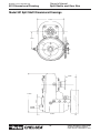
Model 901 Split Shaft Installation Drawings
Vertical Mounting
SPICER 1500 SERIES
RECTANGULAR FLANGE
34"
1511/32"
103/4"
33/8"
DRAIN AND OIL
LEVEL HOLES
/4"-10NC
SPICER 1410 SERIES
RECTANGULAR FLANGE
9
DRIVE SHAFT ANGLE TO
COINCIDE WITH ANGLE
GIVEN IN BODY BUILDERS
LAYOUT BOOK
3
/16"-12NC
SPICER 1500
SERIES FLANGE
BRAKE
BRAKE
ENGAGED DISENGAGED
Horizontal Mounting
BEARING CAP MUST BE
ROTATED UNTIL THE
BREATHER IS IN THE
UP POSITION
SHIFTER COVER MAY BE
ROTATED IN INCREMENTS
OF 90 DEGREES FOR
POSITION DESIRED
3
/4"- 10NC
51/2"
OPTIONAL
MOUNTING
HOLES
Horizontal Mounting
TOTAL
SHIFT 21/16"
14
Parker Hannifin Corporation
Chelsea Products Division
Olive Branch, MS 38654 USA
Bulletin HY25-1202-M1/US
901 Dimensional Drawing
Owner’s Manual
Split Shafts and Gear Box
Model 901 Split Shaft Dimensional Drawings
10.500"
7.500"
4.594"
17.250"
15.281"
15
Parker Hannifin Corporation
Chelsea Products Division
Olive Branch, MS 38654 USA
Bulletin HY25-1202-M1/US
912 Dimensional Drawing
Owner’s Manual
Split Shafts and Gear Box
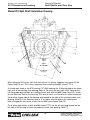
Model 912 Split Shaft Installation Drawing
4.060
15°
15°
J
C
A
B
4.060
When filling the 912 series split shaft unit with oil it is always important not to over fill the
Power Take-Off unit. This is very important when installing two 885 series P.T.O.s.
A change was made to the 912 housing (1-P-484) lowering the fill plug located on the lower
right rear of the housing (see drawing, Note A). To verify that you have a 912 housing that
has the proper plug location for checking the oil level with two 885 Power Take-Offs, check
for the “Revision” level of the housing. This revision level is in the form of a letter located on
the driveline output side of the housing and located to the right of the casting number (see
drawing, Note B). If the Revision letter is “J” or higher then the plug in the housing has
been changed for the correct oil level for two 885 series Power Take-Off.
On all other applications or with one 885 series P.T.O. use the oil level plug located on the
left side of the housing to check for proper oil levels (see drawing, Note C).
16
Parker Hannifin Corporation
Chelsea Products Division
Olive Branch, MS 38654 USA
912 Dimensional Drawing
Owner’s Manual
Split Shafts and Gear Box
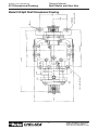
.625- 11 UNC- 2B TH’D
10.708
1.375
2.750
2.250
2.250
5.125
20.352
11.598 REF.
6.500
.656
3.625
TRUNNION
7.250
Model 912 Split Shaft Dimensional Drawing
NO. 328799- 3X REF.
Bulletin HY25-1202-M1/US
17
Parker Hannifin Corporation
Chelsea Products Division
Olive Branch, MS 38654 USA
Bulletin HY25-1202-M1/US
931 Installation Drawing
Owner’s Manual
Split Shafts and Gear Box
Model 931 Split Shaft Installation Drawings
With Cover and Crossmember Support - Below
MOUNTING KIT
328417X
T
N
RA
SM
ISS
ION
A-4
With Cover and Crossmember Support - Above
FR
AM
34"
EW
IDT
H
A-4
TR
S
AN
MIS
SIO
N
MOUNTING KIT
328417X
NOTE: When installing the Split Shaft, the Vent Assembly must be in an upright position.
18
Parker Hannifin Corporation
Chelsea Products Division
Olive Branch, MS 38654 USA
Bulletin HY25-1202-M1/US
931 Dimensional Drawing
Owner’s Manual
Split Shafts and Gear Box
Model 931 Split Shaft Dimensional Drawings
12.875"
12.750"
8.500"
11.500"
8.375"
17.875"
19
Parker Hannifin Corporation
Chelsea Products Division
Olive Branch, MS 38654 USA
Owner’s Manual
Split Shafts and Gear Box
Bulletin HY25-1202-M1/US
941 Installation Drawing
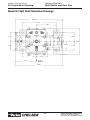
Model 941 Split Shaft Installation Drawings
12.8820"
9.212"
5.386"
2.756"
2.756"
8.086"
2.424"
2.756"
3.826"
5.761"
2.756"
3.000"
P. T. O.
OPENING
12.882"
20
Parker Hannifin Corporation
Chelsea Products Division
Olive Branch, MS 38654 USA
Bulletin HY25-1202-M1/US
941 Dimensional Drawing
Owner’s Manual
Split Shafts and Gear Box
Model 941 Split Shaft Dimensional Drawings
6.068"
15°
4.515"
21
Parker Hannifin Corporation
Chelsea Products Division
Olive Branch, MS 38654 USA
Bulletin HY25-1202-M1/US
Installation of a Gear Box
Owner’s Manual
Split Shafts and Gear Box
Installation Instructions – Gear Boxes Models 700, 712, 721, 732,741,
2230, and 2442
Gear boxes are installed very similarly to split shaft Power Take-Offs. The differences are
that the gear box is driven from a Power Take-Off rather than the transmission main shaft,
and the gear box drives a piece of equipment rather than the rear axle. Installation of a
gear box requires fabrication of new shafts rather than cutting into the existing driveline.
Listed are the necessities for a good gear box installation which are basically the same as
those required for a good split shaft Power Take-Off installation. The unit itself is mounted
on a plate which must be mounted to a sturdy support on the vehicle. Rubber isolation of
the unit is important to prevent transmitting vibrations throughout the vehicle. Then follow
the steps below:
1.
Front—The short coupled joint connecting the Power Take-Off to the gear box should
be installed so as to permit equal joint angles of less than 3°.
Rear—The two joint assembly connecting the gear box to the driven equipment should
be installed so as to permit equal joint angles of less than 5°. To insure the best
performance, the joint angles should be kept within a minimum of 1° to 3°.
Front & Rear—The two joint assemblies at the front and rear should be installed so as
to permit equal joint angles of less than 5°.
2.
Determine a suitable location for mounting the gear box. Raise or lower or move the
gear box front or rear as required to reduce the joint angles to a minimum, but not less
than 1°.
3.
Align the gear box with the Power Take-Off and driven equipment.
A. For the best installation and optimum performance, the input and output shafts of
the gear box should be parallel respectively with 1° to the output shaft of the Power
Take-Off and the input shaft of the driven equipment.
B. With the shafts parallel, the joint angles should be in one plane only. Make sure the
offset in the horizontal or vertical planes will provide for equal joint angles of less
than 3° with a short coupled joint or less than 5° with a two joint assembly.
4.
Excessive angles result in a loss of speed and power. The figures shown below are
approximate and any angles less than those shown will provide a better installation.
Speed
5,000 R.P.M.
4,000 R.P.M.
3,000 R.P.M.
True Joint Operating Angle
3° 15'
4° 15'
5° 50'
Slight angles of 1° in each joint are necessary to permit circulation of the needles.
5.
If at all possible, the shafts front and rear should be assembled, straightened, and
balanced. The various models of gear boxes offer three (or several) types of shifters.
Wire shift is installed identically to a six bolt Power Take-Off installation. Linkage for
lever controls must be designed and fabricated by the installer. Air shift plumbing is
shown in the typical sketch on pages 33-35 for a single acting air shift.
22
Parker Hannifin Corporation
Chelsea Products Division
Olive Branch, MS 38654 USA
Bulletin HY25-1202-M1/US
Breather Hose Installation
Owner’s Manual
Split Shafts and Gear Box
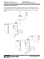
Breather Hose Installation
When installing a breather hose assembly on a gear box or split shaft, the top of the vent
assembly must be at least 12 inches above the unit as shown in figure 1. Figure 2 shows an
incorrect installation. When installing any vent assembly, make sure it is in the upright
position.
304.8
(12.00) MIN.
Fig. 1
Fig. 2
23
Parker Hannifin Corporation
Chelsea Products Division
Olive Branch, MS 38654 USA
Owner’s Manual
Split Shafts and Gear Box
Bulletin HY25-1202-M1/US
Installation–P.T.O. to a Split Shaft
Application Questions for Installation of a P.T.O. to a Split Shaft
Specifying and mounting a P.T.O. to the 912
& 914 Split Shaft is accomplished the same
as on a transmission. There are certain
application questions and installation
procedures that you should follow. The next
four pages will take you through these steps.
1.
What is the make and model of your
transmission?
2.
Which P.T.O. opening will be used?
3.
What accessory is to be driven?
4.
How much horsepower is required to
drive the accessory?
5.
What is the required rotation of the
P. T. O. ?
6.
What is the required P.T.O. output shaft
speed as a percent of engine speed?
7.
S.A.E. 6 Bolt
S.A.E. 8 Bolt
What is the required method of shifting Standard SAE Power Take-Off Apertures
the P.T.O. – cable, lever or air?
Once all the answers to these questions
have been determined, a transmission
mounted P.T.O. can be selected to meet the
horsepower, speed, and rotation that you
require.
DRIVE GEAR TO FRONT
Having made the selection of a P.T.O., you
are ready to start the installation.
P. T. O.
Driver Gear
on right
side of
transmission
P.T.O. Drive Gear Location
The standard location for the P.T.O. drive gear
in the transmission is 1/2" to the front or 1/2"
to the rear of the vertical center line.
24
P. T. O.
Driver Gear
on left
side of
transmission
DRIVE GEAR TO REAR
Parker Hannifin Corporation
Chelsea Products Division
Olive Branch, MS 38654 USA
Owner’s Manual
Split Shafts and Gear Box
Bulletin HY25-1202-M1/US
Installation–P.T.O. to a Split Shaft
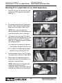
Mounting P.T.O. to Split Shaft for 6 or 8 Bolt Applications
1.
Drain the oil from the transmission, and
remove the P.T.O. aperture cover plate.
(See Fig. 1.)
Fig. 1
2.
Discard the cover plate and cover plate
gasket. Clean the aperture pad using a
putty knife or wire brush. (See Fig. 2.)
NOTE: Stuff a rag in the aperture
opening to prevent dirt from entering the
transmission while you are cleaning it.
3.
Using your hand, rock the P.T.O. drive
gear in the transmission (See Fig. 3.) and
the driven gear in the P.T.O. assembly
(See Fig. 4.). Rocking the gears provides
two important factors.
Fig. 2
A. It shows you the amount of backlash
that has been designed into each unit.
B. It is helpful in establishing the proper
backlash when installing the P.T.O.
4.
Install the proper studs in the P.T.O. aperture pad using a stud driver. (See Fig. 5.)
5.
Where holes are tapped through the
transmission case, use Permatex or an
equivalent to prevent leaks.
Fig. 3
Fig. 4
NOTE: Avoid contact of Permatex with
automatic transmission fluid in
automatics. Always check to be sure the
studs do not interfere with transmission.
Fig. 5
25
Parker Hannifin Corporation
Chelsea Products Division
Olive Branch, MS 38654 USA
Owner’s Manual
Split Shafts and Gear Box
Bulletin HY25-1202-M1/US
Installation–P.T.O. to a Split Shaft
Mounting P.T.O. to Split Shaft (Continued)
6.
Tighten the studs securely, and torque
them to 10 - 15 ft. lbs. (1.38 - 2.07 kg.
meters) for the 6 bolt and 15 - 20 ft. lbs.
(2.07 - 2.77 kg. meters) for the 8 bolt.
(See Fig. 6.)
7.
Place the correct number of gaskets
over the studs. (See Fig. 7.) Do not use
Permatex between gaskets because you
may want to add or subtract gaskets to
obtain the proper backlash.
Fig. 6
• When mounting a P.T.O., use gaskets
between all mounting surfaces.
• Do not stack more than 3 gaskets
together.
• Usually one thick gasket .020"
(.50 mm) will be required.
• Remember the lubricant in the
transmission also lubricates the P.T.O.
Therefore, at least one gasket must
always be used on either side of filler
blocks, adapter assemblies, or
adapter plates. More gaskets may be
required when establishing proper
backlash.
8.
9.
Fig. 7
Secure P.T.O. to the transmission. The
220 Series must always have a copper
washer under its one capscrew head
which goes through the inside of the
housing. (See Fig. 8.)
Fig. 8
Fasten the P.T.O. to the transmission.
Torque the 6 bolt to 30 - 35 ft. lbs.
(4.14 - 4.84 kg. meters) and the 8 bolt to
45 - 50 ft. lbs. (6.22 -6.91 kg. meters).
(See Fig. 9.)
Fig. 9
26
Parker Hannifin Corporation
Chelsea Products Division
Olive Branch, MS 38654 USA
Bulletin HY25-1202-M1/US
Installation–P.T.O. to a Split Shaft
Owner’s Manual
Split Shafts and Gear Box
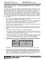
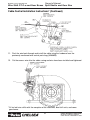
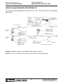
Installation Instructions for 880 Series with “L*” Output, Top Mounted
to 912 Series Split Shaft - Requiring Self-Lube Option
1. Drain split shaft oil at drain plug (A). Filter or screen oil & reuse if desired.
2. Remove top split shaft aperture cover plate at (B) or air shift Assembly (C) & reassemble
to either side of split shaft in place of shipping cover. Install P.T.O. on split shaft & set
backlash at .006" to .012". (See page 28 for checking proper backlash)
3. Install copper gasket (D), screened strain plug (E) & 90° elbow (F) in place of drain plug
at (A). Also install pressure lube hose (G) between elbow (F) and pump (H). (Use pipe
sealant on all pipe threads)
4. Fill split shaft with filtered, screened or new oil at fill plug (J), until oil reaches plug level,
then reinstall plug.
5. Finish P.T.O. & split shaft installation per owner’s manual. Also install shaft and/or pump to
be driven by P.T.O.
6. After brief P.T.O. operation, remove fill plug (J), add oil until it reaches plug level, then
reinstall plug.
IMPORTANT: Lube pump (H) must rotate clockwise (engine rotation) as view from front
of vehicle.
H
B
C
J
G
D
A
F
27
E
Parker Hannifin Corporation
Chelsea Products Division
Olive Branch, MS 38654 USA
Owner’s Manual
Split Shafts and Gear Box
Bulletin HY25-1202-M1/US
Checking Backlash
Checking Backlash
To check for proper backlash on P.T.O.
with shift cover:
1.
Remove the P.T.O. shift housing and/or
inspection plate.
2.
Mount the dial indicator so that it registers
movement in the input gear (driven
gear) of the P.T.O. (See Fig. 10.)
NOTE: See Figure 11 for the proper
Fig. 10
location of the dial indicator’s contact point.
(Two common types of dial indicators are
shown.)
3.
4.
.006
.012 POINTER
INDICATES
SIDE MOVEMENT
Hold the P.T.O. driver gear in the
transmission with a screwdriver or bar, and
rock the P.T.O. input gear (driven gear) back
and forth with your hand. Note the total
movement on the dial indicator.
ALTERNATE
INDICATORS
.006
.012
BACKLASH
Establish backlash at .006" - .012" (.15
mm - .30 mm) by adding or subtracting
gaskets.
.006
.012
P.T.O. INPUT
GEAR
HOLD
TRANS.
P.T.O. DRIVE
GEAR
TRANSMISSION
NOTE: For any additional information on
hooking up the shifter or installation of
the P.T.O., please consult the Owner’s
Manual included with the unit.
.006
.012 PLUNGER
TYPE
POINTER
INDICATES
DEPTH
GASKET PACK
AS REQ’D.
P.T.O. CASE
Fig. 11
General rule—A Chelsea .010" gasket will
change backlash approximately .006." A
.020" gasket changes backlash approximately
.012."
28
Parker Hannifin Corporation
Chelsea Products Division
Olive Branch, MS 38654 USA
Owner’s Manual
Wire Shift P.T.O.s and Gear Boxes Split Shafts and Gear Box
Bulletin HY25-1202-M1/US
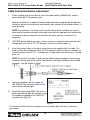
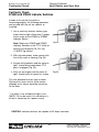
Cable Control Installation Instructions*
1.
Find a suitable area on the dash to install the cable control (328346-10X) and the
control plate (68-P-18) indicator light.
Optional Location: As an option the control cable and knob can be located through floor.
Using this option the control plate and indicator light should still be located on dash, in
close proximity.
NOTE: The location of the cable control and the control plate should be as close to
each other as possible and easily accessible by the driver or operator, but should not be
an obstacle to driver movement nor interfere with other controls, instruments, or
equipment.
2.
CAUTION: Before drilling any holes, make sure there is adequate room on both sides
through dash wall, drill a 1/2" (.5") diameter hole for the control cable. [1]
3.
Install the control cable on the dash using the hex nuts supplied with the cable. The
knob can then be screwed into place [2]. The length of cable can then run through the
firewall and back to the P.T.O. —making sure it is kept away from the exhaust, moving
parts, etc.
NOTE: Do not kink the cable. In order for the cable to operate properly, there can be
no bends smaller than 6 inch radius. Total bends in the cable should not exceed 360°
(example - four 90° bends in cable).
4.
Using the template found on page 38
(SK-168) drill the necessary holes for the
control plate-indicator light.
5.
Install the control plate (68-P-18) stick on
decal and indicator light on the dash using
the hardware supplied in the 328751-1X
installation kit (Fig. 25).
Fig. 25
* All six bolt wire shifts with the exception of the reversible, dual shift units, and some
gear boxes.
29
Parker Hannifin Corporation
Chelsea Products Division
Olive Branch, MS 38654 USA
Owner’s Manual
Wire Shift P.T.O.s and Gear Boxes Split Shafts and Gear Box
Bulletin HY25-1202-M1/US
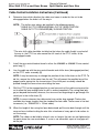
Cable Control Installation Instructions (Continued)
6.
Determine from which direction the cable must come in order for the unit to be
disengaged when the knob is all the way in.
NOTE: The shifter must always be installed in the following manner:
* CABLE IN: P.T.O. DISENGAGED(6A): OUT OF GEAR POSITION
CABLE OUT: P.T.O. ENGAGED(6B): IN GEAR POSITION
* The wire shift cable should be installed so that when the cable (knob) is pushed all
the way in, the P.T.O. has also moved the full travel of the P.T.O. shifter, to the
disengaged mode.
7.
Install the wire control bracket found in either the 328380X or 328380-1X wire control
parts bag. [7]
8.
Line the cable up with the wire control bracket and shifter lever (disengaged position)
on the P.T.O. cover assembly [8]
NOTE: It may be necessary to change the position of the shifter lever on the P.T.O. To
do this, remove the shifter cover from the unit. This will prevent the possible loss of the
poppet and/or spring into the transmission if the shifter post assembly should be
pushed through the cover when reinstalling the lever.
9.
Shift the P.T.O. to the engaged position to see how much of the cable casing must be
cut to allow the lever enough travel to shift in and out completely. The casing need only
go just beyond the bracket, whereas, the wire must be long enough to go through the
swivel pin in the shifter lever. [9]
NOTE: In some instances the cable control may not be long enough. Chelsea has
available four longer lengths than the standard ten-foot cable. These come in five foot
increments (i.e., 328346-15X = 15-foot cable).
10. When the length of the casing has been determined, pull the wire back through until the
case can be cut without cutting the wire. Use a hacksaw or heavy pair of side cutters to
cut the casing.
NOTE: The cable can be held by a bench vise as long as the jaws are not tightened to
the point where the case mushrooms. If a vise is not accessible, a pair of vise grips will
do the job.
30
Parker Hannifin Corporation
Chelsea Products Division
Olive Branch, MS 38654 USA
Owner’s Manual
Wire Shift P.T.O.s and Gear Boxes Split Shafts and Gear Box
Bulletin HY25-1202-M1/US
Cable Control Installation Instructions* (Continued)
11. Push the wire back through and install the cable using the hardware from the
previously mentioned wire control parts bag (328380X).
12. Cut the excess wire after the cable casing and wire have been installed and tightened.
* All six bolt wire shifts with the exception of the reversible, dual shift units, and some
gear boxes.
31
Parker Hannifin Corporation
Chelsea Products Division
Olive Branch, MS 38654 USA
Owner’s Manual
Wire Shift P.T.O.s and Gear Boxes Split Shafts and Gear Box
Bulletin HY25-1135-M1/US
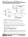
Cable Control Installation Instructions* (Continued)
Indicator Light Installation
Sketch (SK-286 Rev G)
CAUTION: Indicator switches are capable of 0.5 amps maximum.
NOTE: All wires and cables must be clear of heat source and moving parts.
13. Shift the P.T.O. to insure enough casing has been removed to allow full gear
engagement.
14. Install the wiring for the indicator light using the schematic above (SK-286 Rev G).
NOTE: Check both the cable and indicator light wires to be certain that they are not
near the exhaust system or any moving parts. Carefully fasten to stationary parts of
the vehicle if necessary.
15. Shift the P.T.O. The following should be adhered to:
15A. CABLE IN: P.T.O. DISENGAGED: LIGHT OUT
15B. CABLE OUT: P.T.O. ENGAGED: LIGHT ON
NOTE: The P.T.O. should be checked for continuity as per the instructions in this manual.
NOTE: Cable must be rigidly mounted-possibly to the transmission within 12-24" of the
P. T. O.
* All six bolt wire shifts with the exception of the reversible, dual shift units, and some
gear boxes.
32
Parker Hannifin Corporation
Chelsea Products Division
Olive Branch, MS 38654 USA
33
Caution: When installing nylon tubing avoid sharp angles, exhaust and manifold systems.
Important: When this installation is used on vehicles with automatic transmissions, the P. T.O. drive gear must be stopped
before shifting.
NOTE: Tube nut is reusable as long as nylon tubing is not removed from the tube nut.
• The template for the control plate is on page 36.
Air Shift Installation Sketch
Warning: Connect directly to the air supply. Do not use tubing between the air supply and the pressure protection valve.
Bulletin HY25-1202-M1/US
Owner’s Manual
Split Shafts and Gear Box
Air Shift Installation Sketch for the 2442 Series Gear Box (SK-231 Rev D)
Parker Hannifin Corporation
Chelsea Products Division
Olive Branch, MS 38654 USA
Bulletin HY25-1202-M1/US
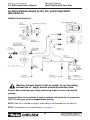
Air Shift Installation Sketch
Owner’s Manual
Split Shafts and Gear Box
Air Shift Installation Sketch for 901, 912, and 941 Split Shafts
(SK-276 Rev G)
328388-61X Installation Kit
Warning: Connect directly to the air supply. Do not use tubing
between the air supply and the pressure protection valve.
Caution: When installing nylon tubing avoid sharp angles, exhaust and manifold
systems.
Important: When this installation is used on vehicles with automatic transmissions,
the P.T.O. drive gear must be stopped before shifting.
NOTE: Tube nut is reusable as long as nylon tubing is not removed from the tube nut.
NOTE: The template for the control plate is on page 37.
34
Parker Hannifin Corporation
Chelsea Products Division
Olive Branch, MS 38654 USA
Bulletin HY25-1202-M1/US
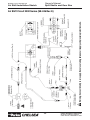
Air Shift Installation Sketch
Owner’s Manual
Split Shafts and Gear Box
35
Warning: Connect directly to air supply. Do not use tubing between air supply and pressure protection valve.
To 230, 231, 236 Series
P. T. O. Inlet Port
Air Shift Circuit 2230 Series (SK-246 Rev E)
Parker Hannifin Corporation
Chelsea Products Division
Olive Branch, MS 38654 USA
Owner’s Manual
Split Shafts and Gear Box
Bulletin HY25-1202-M1/US
Dash Drilling Template
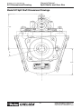
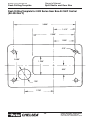
Dash Drilling Template for 2442 Series Gear Box Air Shift Control
(SK-204 Rev C)
3.688"
1.312"
2.500"
1.250"
.219"
2.000"
1.250"
.625"
.750"
1.750"
36
Parker Hannifin Corporation
Chelsea Products Division
Olive Branch, MS 38654 USA
Owner’s Manual
Split Shafts and Gear Box
Bulletin HY25-1202-M1/US
Dash Drilling Template
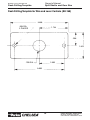
Dash Drilling Template for 901, 912, and 941 Split Shafts Air
Shift Controls (SK-204 Rev C)
3.688"
1.312"
1.750"
.875"
.219
2.688"
2.000"
.625"
1.344"
.750"
1.750"
37
Parker Hannifin Corporation
Chelsea Products Division
Olive Branch, MS 38654 USA
Owner’s Manual
Split Shafts and Gear Box
Bulletin HY25-1202-M1/US
Dash Drilling Template
Dash Drilling Template for Wire and Lever Controls (SK-168)
3.468
.203 DIA.
2 PLACES
1.734
.906
1.812
.750 DIA.
1.500
3.000
38
Parker Hannifin Corporation
Chelsea Products Division
Olive Branch, MS 38654 USA
Bulletin HY25-1202-M1/US
Dash Drilling Template
Owner’s Manual
Split Shafts and Gear Box
Indicator Light Installation (SK-286 Rev G)
For wire and lever shift option on the 700, 712, 721, 732, 741, 901, 912, 931, 941 and 2442
gear boxes.
Caution: Indicator switches are capable of 0.5 amps maximum.
NOTE: All wires and cables must be clear of heat source and moving parts.
39
Parker Hannifin Corporation
Chelsea Products Division
Olive Branch, MS 38654 USA
Owner’s Manual
Split Shafts and Gear Box
Bulletin HY25-1202-M1/US
Continuity Check
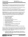
Continuity Check
379639 and 379652 Indicator Switches
In order to insure that the switch is
functioning properly, the following procedure
can be used with the unit on a bench, or
installed.
1. Use a continuity checker, battery type,
either meter or light. Attach one (1) probe
to the screw on the 379639 or 379652
Indicator Switch.
Note: Make sure 379639 and 379652
Indicator Switches in the P.T.O. shifter or
housing are torqued to 10-15 ft. lbs.
(1.38-2.07 kg meters).
Fig. 23
2. With the other probe, make contact with
the shifter cover or housing (Fig. 23).
3. Actuate shifting device and the meter or
light* should be actuated when P.T.O.
gear is engaged (Fig. 24).
4. Shift unit out of gear and the meter or
light* should return to normal as shown.
Fig. 24
This test procedure can be used to check
Chelsea wire, lever, and air shifter covers,
although an air source would be necessary
for the latter.
* If a meter is not available the light in the
328751-1X can be used. A six volt battery is
all that is necessary for a power source.
CAUTION: Indicator switches are capable of 0.5 amps maximum.
40
Parker Hannifin Corporation
Chelsea Products Division
Olive Branch, MS 38654 USA
Bulletin HY25-1202-M1/US
Troubleshooting
Owner’s Manual
Split Shafts and Gear Box
Troubleshooting
Driver Training: One of the major causes of bearing and gear failures in the auxiliary unit
is poor driving habits. Drivers should be taught to always use the Lo Speed or reductions
available in the auxiliary unit and keep the front box in the higher ratios not vice versa.
Worn and pitted gears, as well as worn and pitted bearings are usually caused by excessive
use of the auxiliary overdrive gears with the mainbox in lower gear ratios.
Broken teeth in the auxiliary unit are usually caused by drivers trying to start their vehicles
with the auxiliary unit in the high ratio while the big reduction is made in the front box.
Frogging or quick release of clutch gives a jump start which is also noted for breaking teeth.
Noisy Operation: Noise is usually very elusive and generally not the fault of the auxiliary;
therefore, mechanics should road test to determine if the driver’s complaint of noise is
actually in the auxiliary. Remember that auxiliary units act as sounding boxes and in
numerous instances, drivers have insisted that the noise was in the auxiliary. However,
investigations revealed the noise to be caused by one of the following conditions:
A.
B.
C.
D.
E.
F.
G.
H.
I.
J.
K.
L.
M.
N.
O.
P.
Fan out of balance or bent blades.
Defective vibration dampers.
Crankshafts out of balance.
Flywheels out of balance.
Flywheels mounting bolts loose.
Engine rough at idle producing rattle in gear train.
Clutch assembly out of balance.
Engine mounts loose or broken.
P.T.O. gear not fully engaged or housing not properly shimmed.
Universal joints wornout.
Propeller shafts out of balance.
Universal joint angles out of plane or at an excessive angle.
Center bearings in driveline dry, not mounted properly, etc.
Wheels out of balance.
Tire treads humming or vibrating at certain speeds.
Air leaks on suction side of induction system—especially with turbo-chargers.
Mechanics should try to locate and eliminate noise by means other than auxiliary removal,
or overhaul. However, if the noise appears to be in the auxiliary, try to break it down into the
following classifications. If possible, determine what position the gear shift lever is in when
the noise occurs. If the noise is evident in only one gear position, the cause of the noise is
generally traceable to the gears in operation.
A.
Growling and humming or, more serious, a grinding noise. These noises are
caused by worn, chipped, rough, or cracked gears. As gears continue to wear, the
grinding noise will be noticeable, particularly in the gear position that throws the
greatest load on the worn gear.
41
Parker Hannifin Corporation
Chelsea Products Division
Olive Branch, MS 38654 USA
Bulletin HY25-1202-M1/US
Troubleshooting
Owner’s Manual
Split Shafts and Gear Box
Troubleshooting
B.
Hissing or, more serious, a thumping or bumping type noise. Hissing noises can
be caused by bad bearings. As bearings wear and retainers start to break up, etc.,
the noise could change to a thumping or bumping.
C.
Metallic rattles within the auxiliary usually result from a variety of conditions.
Engine torsional vibrations are transmitted to the transmission through the clutch,
which may be amplified and transmitted to the auxiliary through the connecting
propeller shaft. In heavy duty equipment, clutch discs with vibration dampers are
not used, so a rattle, particularly in neutral, is common with diesel equipment. In
general, engine speeds should be 600 R.P.M. or above to eliminate objectionable
rattles and vibration during the idle. Always leave the main box in neutral and the
auxiliary unit in gear when idling. A defective or faulty injector would cause a
rough or lower idle speed and a rattle in the auxiliary. Rattle could also be caused
by excessive backlash in P.T.O. unit mounting.
D.
Improper lubricants or lack of lubricant can produce noises. Auxiliaries with low
oil levels sometimes run hotter than normal, as there is insufficient lubricant to
cool and cover the gears.
E.
Squealing, particularly when the auxiliary is operating at higher speeds, could be
caused by one of the free running gears seizing on the thrust face or fluted
diameter temporarily and then letting go. In general, a mild seizure will clear itself
up and the auxiliary will continue to operate satisfactorily without this defect being
known. See “G.”
F.
Gear seizure at High Speed, usually accompanied with a loud squealing noise,
is readily apparent to the driver, since the truck will suddenly slow down as if the
brakes were being applied. If the truck continues to move ahead, even though
the gear shift lever is placed in neutral, it would indicate the floating gear on the
main shaft had seized. Depressing the clutch should interrupt the driving torque.
The seized gear could be checked quite readily by depressing the clutch and
checking the action with the gear shift lever progressively in all shift positions. If
releasing the clutch tends to kill the engine, then this gear position has not
seized. In other words, the auxiliary would be in two gears at the same time. By a
process of elimination, the gear at fault can be readily identified. See “G.”
G.
Vibration. Gear seizures on thrust faces or fluted diameters are usually caused
by vibrations in the power train. This could be engine, propeller shafts, joint
angles, rear axles, differentials, etc.
42
Parker Hannifin Corporation
Chelsea Products Division
Olive Branch, MS 38654 USA
Bulletin HY25-1202-M1/US
Power Take-Off Maintenance
Owner’s Manual
Split Shafts and Gear Box
Power Take-Off Maintenance
Due to the normal and sometime severe torsional vibrations that Power Take-Off units
experience, operators should follow a set maintenance schedule for inspections. Failure to
service loose bolts or Power Take Off leaks could result in potential auxiliary Power Take-Off
or transmission damage.
Periodic P.T.O. MAINTENANCE is required by the owner/operator to ensure proper, safe and
trouble free operation.
Daily:
Check all air, hydraulic and working mechanisms before operating
P.T.O. Perform maintenance as required.
Monthly:
Inspect for possible leaks and tighten all air, hydraulic and
mounting hardware, if necessary. Torque all bolts, nuts, etc.
to Chelsea specifications. Insure that splines are properly
lubricated, if applicable. Perform maintenance as required.
With regards to the direct mounted pump splines, the P.T.O. requires the application of a
specially formulated anti-fretting, high pressure, high temperature grease. The addition of
the grease has been proven to reduce the effects of the torsional vibrations, which result in
fretting corrosion on the P.T.O. internal splines as well as the pump external splines. Fretting
corrosion appears as a “rusting and wearing” of the pump shaft splines. Severe duty
applications, which require long P.T.O. running times and high torque may require more
frequent regreasing. Applications such as Utility Trucks that run continuously and are lightly
loaded also require frequent regreasing due to the sheer hours of running time. It is
important to note that service intervals will vary for each and every application and is the
responsibility of the end user of the product. Chelsea also recommends that you consult
your pump owners manuals and technical services for their maintenance guidelines.
Fretting corrosion is caused by many factors and without proper maintenance; the anti-fretting
grease can only reduce its effects on components.
Chelsea offers the grease to our customers in two packages. The first is a 5/8 fluid ounce
tube (379688), which is included with every applicable P.T.O., and the second is a 14-ounce
grease cartridge (379831). Chelsea also offers greaseable shafts for most all output
designators.
Warranty:
Failure to comply entirely with the provisions set forth in the appropriate
Owner’s Manual will result in voiding of ALL Warranty consideration.
43
Parker Hannifin Corporation
Chelsea Products Division
Olive Branch, MS 38654 USA
Offer of Sale
The items described in this document and other documents or descriptions provided by Parker Hannifin Corporation, its subsidiaries and
its authorized distributors are hereby offered for sale at prices to be established by Parker Hannifin Corporation, its subsidiaries and its
authorized distributors. This offer and its acceptance by any customer ("Buyer") shall be governed by all of the following Terms and
Conditions. Buyer’s order for any such items, when communicated to Parker Hannifin Corporation, its subsidiary or an authorized
distributor ("Seller") verbally or in writing, shall constitute acceptance of this offer.
1. Terms and Conditions of Sale: All descriptions, quotations,
proposals, offers, acknowledgments, acceptances and sales of
Seller’s products are subject to and shall be governed exclusively
by the terms and conditions stated herein. Buyer’s acceptance of
any offer to sell is limited to these terms and conditions. Any terms
or conditions in addition to, or inconsistent with those stated herein,
proposed by Buyer in any acceptance of an offer by Seller, are
hereby objected to. No such additional, different or inconsistent
terms and conditions shall become part of the contract between
Buyer and Seller unless expressly accepted in writing by Seller.
Seller’s acceptance of any offer to purchase by Buyer is expressly
conditional upon Buyer’s assent to all the terms and conditions
stated herein, including any terms in addition to, or inconsistent
with those contained in Buyer’s offer, Acceptance of Seller’s
products shall in all events constitute such assent.
2. Payment: Payment shall be made by Buyer net 30 days from the
date of delivery of the items purchased hereunder. Amounts not
timely paid shall bear interest at the maximum rate permitted by law
for each month or portion thereof that the Buyer is late in making
payment. Any claims by Buyer for omissions or shortages in a
shipment shall be waived unless Seller receives notice thereof
within 30 days after Buyer’s receipt of the shipment.
3. Delivery: Unless otherwise provided on the face hereof, delivery shall be made F.O.B. Seller’s plant. Regardless of the method
of delivery, however, risk of loss shall pass to Buyer upon Seller’s
delivery to a carrier. Any delivery dates shown are approximate
only and Seller shall have no liability for any delays in delivery.
4. Warranty: Seller warrants that the items sold hereunder shall
be free from defects in material or workmanship for a period of:
(A) All Power Take-Off units one (1) year from date of installation.
(B) Except 267, 277, 278, 242, 244, 245, 250, 251 and 859 series
two (2) years from date of installation.
THIS WARRANTY COMPRISES THE SOLE AND ENTIRE WARRANTY PERTAINING TO ITEMS PROVIDED HEREUNDER.
SELLER MAKES NO OTHER WARRANTY, GUARANTEE, OR
REPRESENTATION OF ANY KIND WHATSOEVER. ALL OTHER
WARRANTIES, INCLUDING BUT NOT LIMITED TO, MERCHANTABILITY AND FITNESS FOR PURPOSE, WHETHER
EXPRESS, IMPLIED, OR ARISING BY OPERATION OF LAW,
TRADE USAGE, OR COURSE OF DEALING ARE HEREBY
DISCLAIMED. NOTWITHSTANDING THE FOREGOING, THERE
ARE NO WARRANTIES WHATSOEVER ON ITEMS BUILT OR
ACQUIRED WHOLLY OR PARTIALLY, TO BUYER’S DESIGNS
OR SPECIFICATIONS.
5. Limitation Of Remedy: SELLER’S LIABILITY ARISING FROM
OR IN ANY WAY CONNECTED WITH THE ITEMS SOLD OR
THIS CONTRACT SHALL BE LIMITED EXCLUSIVELY TO REPAIR OR REPLACEMENT OF THE ITEMS SOLD OR REFUND
OF THE PURCHASE PRICE PAID BY BUYER, AT SELLER’S
SOLE OPTION. IN NO EVENT SHALL SELLER BE LIABLE FOR
ANY INCIDENTAL, CONSEQUENTIAL OR SPECIAL DAMAGES
OF ANY KIND OR NATURE WHATSOEVER, INCLUDING BUT
NOT LIMITED TO LOST PROFITS ARISING FROM OR IN ANY
WAY CONNECTED WITH THIS AGREEMENT OR ITEMS SOLD
HEREUNDER, WHETHER ALLEGED TO ARISE FROM BREACH
OF CONTRACT, EXPRESS OR IMPLIED WARRANTY, OR IN
TORT, INCLUDING WITHOUT LIMITATION, NEGLIGENCE,
FAILURE TO WARN OR STRICT LIABILITY.
6. Changes, Reschedules and Cancellations: Buyer may request to modify the designs or specifications for the items sold
hereunder as well as the quantities and delivery dates thereof, or
may request to cancel all or part of this order, however, no such
requested modification or cancellation shall become part of the
contract between Buyer and Seller unless accepted by Seller in a
written amendment to this Agreement. Acceptance of any such
requested modification or cancellation shall be at Seller’s discretion, and shall be upon such terms and conditions as Seller may
require.
7. Special Tooling: A tooling charge may be imposed for any
special tooling, including without limitation, dies, fixtures, molds
and patterns, acquired to manufacture items sold pursuant to this
contract. Such special tooling shall be and remain Seller’s property
notwithstanding payment of any charges by Buyer. In no event will
Buyer acquire any interest in apparatus belonging to Seller which
is utilized in the manufacture of the items sold hereunder, even if
such apparatus has been specially converted or adapted for such
manufacture and notwithstanding any charges paid by Buyer.
Unless otherwise agreed, Seller shall have the right to alter, discard
or otherwise dispose of any special tooling or other property in its
sole discretion at any time.
8. Buyer’s Property: Any designs, tools, patterns, materials,
drawings, confidential information or equipment furnished by Buyer
or any other items which become Buyer’s property, may be considered obsolete and may be destroyed by Seller after two (2)
consecutive years have elapsed without Buyer placing an order for
the items which are manufactured using such property, Seller shall
not be responsible for any loss or damage to such property while
it is in Seller’s possession or control.
9. Taxes: Unless otherwise indicated on the face hereof, all prices
and charges are exclusive of excise, sales, use, property, occupational or like taxes which may be imposed by any taxing authority
upon the manufacture, sale or delivery of the items sold hereunder.
If any such taxes must be paid by Seller or if Seller is liable for the
collection of such tax, the amount thereof shall be in addition to the
amounts for the items sold. Buyer agrees to pay all such taxes or
to reimburse Seller therefore upon receipt of its invoice. If Buyer
claims exemption from any sales, use or other tax imposed by any
taxing authority, Buyer shall save Seller harmless from and against
any such tax, together with any interest or penalties thereon which
may be assessed if the items are held to be taxable.
10. Indemnity For Infringement of Intellectual Property Rights:
Seller shall have no liability for infringement of any patents, trademarks, copyrights, trade dress, trade secrets or similar rights
except as provided in this Part 10. Seller will defend and indemnify
Buyer against allegations of infringement of U.S. Patents, U.S.
Trademarks, copyrights, trade dress and trade secrets (hereinafter
‘Intellectual Property Rights’). Seller will defend at its expense and
will pay the cost of any settlement or damages awarded in an action
brought against Buyer based on an allegation that an item sold
pursuant to this contract infringes the Intellectual Property Rights
of a third party. Seller’s obligation to defend and indemnify Buyer
is contingent on Buyer notifying Seller within ten (10) days after
Buyer becomes aware of such allegations of infringement, and
Seller having sole control over the defense of any allegations or
actions including all negotiations for settlement or compromise. If
an item sold hereunder is subject to a claim that it infringes the
Intellectual Property Rights of a third party, Seller may, at its sole
expense and option, procure for Buyer the right to continue using
said item, replace or modify said item so as to make it noninfringing,
or offer to accept return of said item and return the purchase price
less a reasonable allowance for depreciation. Notwithstanding the
foregoing, Seller shall have no liability for claims of infringement
based on information provided by Buyer, or directed to items
delivered hereunder for which the designs are specified in whole or
part by Buyer, or infringements resulting from the modification,
combination or use in a system of any item sold hereunder. The
foregoing provisions of this Part 10 shall constitute Seller’s sole and
exclusive liability and Buyer’s sole and exclusive remedy for
infringement of Intellectual Property Rights.
If a claim is based on information provided by Buyer or if the design
for an item delivered hereunder is specified in whole or in part by
Buyer, Buyer shall defend and indemnify Seller for all costs,
expenses or judgments resulting from any claim that such item
infringes any patent, trademark, copyright, trade dress, trade
secret or any similar right.
11. Force Majeure: Seller does not assume the risk of and shall not
be liable for delay or failure to perform any of Seller’s obligations by
reason of circumstances beyond the reasonable control of Seller
(hereinafter ‘Events of Force Majeure’). Events of Force Majeure
shall include without limitation, accidents, acts of God, strikes or
labor disputes, acts, laws, rules or regulations of any government
or government agency, fires, floods, delays or failures in delivery of
carriers or suppliers, shortages of materials and any other cause
beyond Seller’s control.
12. Entire Agreement/Governing Law: The terms and conditions set forth herein, together with any amendments, modifications and any different terms or conditions expressly accepted by
Seller in writing, shall constitute the entire Agreement concerning
the items sold, and there are no oral or other representations or
agreements which pertain there/to. This Agreement shall be
governed in all respects by the law of the State of Ohio. No
actions arising out of the sale of the items sold hereunder or this
Agreement may be brought by either party more than two (2)
years after the cause of action accrues.
9/01-P
44
Parker Hannifin Corporation
Chelsea Products Division
Olive Branch, MS 38654 USA
Parker Hannifin Corporation
Chelsea Products Division
8225 Hacks Cross Road
Olive Branch, Mississippi 38654 USA
Tel: (662) 895-1011
Fax: (662) 895-1019
www.parker.com/chelsea
FP 01/05 1.5M