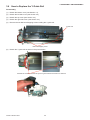
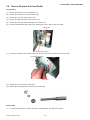
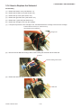
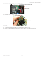
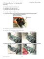
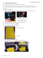
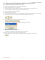
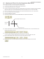
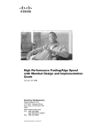
1
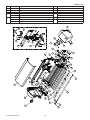
Craft ROBO
CC200-20
MANUAL NO. CC200-UM-251
SERVICE MANUAL
�
CC200-UM-251-02-9370
HISTORY OF REVISIONS
No. Date issued
Description of revision
1
06.08.31
First printing
2
07.03.01 Procedure for the pne force adjustment was changed.
3
07.03.01 Recommended parts list was deleted. (Section 2)
CC200-UM-251-9370
i
Page
All
4-2 to 4-5
All
Edition
01
02
02
CONTENTS
1 PARTS NAMES and FUNCTIONS ................................ 1-1
2 LIST OF TOOLS ............................................................ 2-1
3 DISASSEMBLY AND REASSEMBLY............................ 3-1
3.1
How to Replace the Bottom Cover ...................................................3-1
3.2
How to Replace the Left Side Cover.................................................3-2
3.3
How to Replace the Top Cover .........................................................3-3
3.4
How to Replace the Right Side Cover ..............................................3-4
3.5
How to Replace the Main Board .......................................................3-5
3.6
How to Replace the Y Guide Rail ......................................................3-6
3.7
How to Replace the Pressure Shaft Assembly ................................3-8
3.8
How to Replace the Feed Roller .....................................................3-10
3.9
How to Replace the Y Motor ............................................................ 3-11
3.10 How to Replace the X Motor............................................................3-12
3.12 How to Replace the Y Belt ...............................................................3-13
3.13 How to Replace the Y Flexible Cable .............................................3-15
3.14 How to Replace the Solenoid ..........................................................3-16
3.15 How to Replace the Auto-Registration Mark Sensor Board .........3-18
3.16 How to Replace the Carriage Unit ..................................................3-19
4 ELECTRICAL ADJUSTMENTS ..................................... 4-1
4.1
Using the Adjustment Software ........................................................4-1
4.2
Adjusting the Pen Force ....................................................................4-3
4.3
Adjusting the Auto-Registration Mark Sensor White Level ...........4-6
4.4
Adjusting the Offset of the Auto-Registration Mark Sensor ..........4-7
4.5
Adjusting the Distance Accuracy .....................................................4-9
5 PARTS LISTS ................................................................ 5-1
CC200-UM-251-9370
ii
5.1
Main Unit Parts ...................................................................................5-1
5.2
Bottom Parts.......................................................................................5-3
5.3
Other....................................................................................................5-4
6 BLOCK DIAGRAM ........................................................ 6-1
CC200-UM-251-9370
iii
1 PARTS NAMES and FUNCTIONS
1 PARTS NAMES and FUNCTIONS
Craft ROBO (CC200-20)
Push rollers
Cutting head (carriage)
Front guide
Cutting mat
Guide line
Standby switch
Media rollers
Clamp bracket
Feed knob
AC adapter jack
USB interface connector
Cutting head ........................ Drives the blade holder/pen holder to the left or right
Clamp bracket ..................... Holds the blade holder/pen holder and drives it up or down
Standby switch .................... Turns the power supply to the Craft ROBO on and off. When the power supply is on,
the switch’s lamp lights blue.
Feed knob ........................... Used to manually feed the media back and forth
USB interface connector ..... Used for connecting the USB cable
AC adapter jack .................. Used for connecting the AC adapter cable
Cutting mat ......................... Cutting or plotting is performed on this surface
Push rollers ......................... Hold the media in place against the media rollers
Media rollers ....................... Move the media back and forth
Front guide .......................... Used as the work surface
Guide line ........................... Used as a guide when media is loaded
CC200-UM-251-9370
1-1
2 LIST OF TOOLS
2 LIST OF TOOLS
No.
1
2
3
Adjustment Item
Pen force adjustment
Distance adjustment
Jigs
Blade and blade holder, Electrical adjustment program
Tools
Colex gauge (150 g, 300 g, 500 g),
Blade and blade holder, Electrical adjustment program
PC, USB I/F cable
Glass scale 300 mm, PC, USB I/F
Auto Registration adjust- Blade and blade holder, Electrical adjustment program
ment
Electrical adjustment program
A4SetEnglish.exe
:Use for the setup of A4-size models
LetterSetEnglish.exe
:Use for the setup of letter-size models
GITKUSBP.dll
:USB driver for the setup programs
CC200-UM-251-9370
2-1
cable
PC, USB I/F cable
3 DISASSEMBLY AMD REASSEMBLY
3 DISASSEMBLY AND REASSEMBLY
3.1
How to Replace the Bottom Cover
Disassembly
(1)
Remove the four M3L8 self-tapping screws holding the bottom cover and the rubber feet.
Bottom cover
M3L8 self-tapping screw
(2)
Detach the bottom cover and the rubber feet.
Reassembly
(1)
To attach the bottom cover, perform the above “Disassembly” procedure in reverse.
CC200-UM-251-9370
3-1
3 DISASSEMBLY AMD REASSEMBLY
3.2
How to Replace the Left Side Cover
Disassembly
(1)
Detach the bottom cover (see Section 3.1).
(2)
Pull out the feed knob from the left side of the unit, and then detach the feed knob.
Feed knob
(3)
Remove the three M3L8 self-tapping screws holding the left side cover.
M3L8 self-tapping screw
(4)
Detach the left side cover.
Reassembly
(1)
To attach the left side cover, perform the above “Disassembly” procedure in reverse.
CC200-UM-251-9370
3-2
3 DISASSEMBLY AMD REASSEMBLY
3.3
How to Replace the Top Cover
Disassembly
(1)
Detach the left side cover (see Section 3.2).
(2)
Pull out the top cover from the right side cover to detach the top cover.
Top cover
Reassembly
(1)
To attach the top cover, perform the above “Disassembly” procedure in reverse.
CC200-UM-251-9370
3-3
3 DISASSEMBLY AMD REASSEMBLY
3.4
How to Replace the Right Side Cover
Disassembly
(1)
Detach the bottom cover (see Section 3.1).
(2)
Remove the three M3L8 self-tapping screws holding the right side cover.
Note:
Hold the right side cover after you have removed the screws; there is a cable inside the cover.
M3L8 self-tapping screw
(3)
Disconnect the standby switch cable which is connected to the standby switch board, and then detach the
right side cover.
Standby switch cable
Reassembly
(1)
To attach the right side cover, perform the above “Disassembly” procedure in reverse.
CC200-UM-251-9370
3-4
3 DISASSEMBLY AMD REASSEMBLY
3.5
How to Replace the Main Board
Disassembly
(1)
Detach the bottom cover (see Section 3.1).
(2)
Detach the right side cover (see Section 3.4).
(3)
Remove the three M3L6 self-tapping screws holding the main board and the shield sheet.
Main board & shield sheet
M3L6 self-tapping screw
(4)
Detach the main board and the shield sheet from the main chassis.
(5)
Disconnect all the cables from the main board.
Main board
Y flexible cable
Y motor cable
X motor cable
Standby switch cable
Reassembly
(1)
To attach the main board, perform the above “Disassembly” procedure in reverse.
(2)
Do not misconnect the cables when connecting the X and Y motor cables to the main board.
(3)
Perform the electrical adjustments described in Chapter 5 after you have replaced the main board.
CC200-UM-251-9370
3-5
3 DISASSEMBLY AMD REASSEMBLY
3.6
How to Replace the Y Guide Rail
Disassembly
(1)
Detach the bottom cover (see Section 3.1).
(2)
Detach the left side cover (see Section 3.2).
(3)
Detach the top cover (see Section 3.3).
(4)
Detach the right side cover (see Section 3.4).
(5)
Remove the two M3L6 self-tapping screws holding the Y guide rail.
Y guide rail
M3L6 self-tapping screw
(6)
Detach the Y guide rail as shown in the picture below.
Release the notches, and then lift up the Y guide rail from the bottom to detach it.
CC200-UM-251-9370
3-6
3 DISASSEMBLY AMD REASSEMBLY
(7)
Release the Y flexible cable clamps to detach the cable from the Y guide rail.
Release the Y flexible cable clamps to
Y flexible cable
detach the cable from the Y guide rail.
Y guide rail
Reassembly
(1)
To attach the Y guide rail, perform the above “Disassembly” procedure in reverse.
CC200-UM-251-9370
3-7
3 DISASSEMBLY AMD REASSEMBLY
3.7
How to Replace the Pressure Shaft Assembly
Disassembly
(1)
Detach the bottom cover (see Section 3.1).
(2)
Detach the left side cover (see Section 3.2).
(3)
Detach the top cover (see Section 3.3).
(4)
Detach the right side cover (see Section 3.4).
(5)
Detach the Y belt tension spring from the left base bracket.
Y belt tension spring
(6)
Y belt tension spring
Remove the two M3L6 self-tapping screws holding the left base bracket, and then detach the left base bracket.
Left base bracket
Left base bracket
M3L6 self-tapping screw
(7)
Lift up the left side of the pressure bracket, and then slide the pressure shaft assembly to the left side.
Left pressure bracket
Pressure shaft assembly
CC200-UM-251-9370
3-8
3 DISASSEMBLY AMD REASSEMBLY
(6)
Detach the pressure shaft assembly as shown in the picture below.
Pressure shaft assembly
Reassembly
(1)
To attach the pressure shaft assembly, perform the above “Disassembly” procedure in reverse.
CC200-UM-251-9370
3-9
3 DISASSEMBLY AMD REASSEMBLY
3.8
How to Replace the Feed Roller
Disassembly
(1)
Detach the bottom cover (see Section 3.1).
(2)
Detach the left side cover (see Section 3.2).
(3)
Detach the top cover (see Section 3.3).
(4)
Detach the right side cover (see Section 3.4).
(5)
Detach the pressure shaft assembly (see Section 3.7).
(6)
Remove the M3L8 binding head screw holding the X drive gear to the feed roller.
X drive gear
M3L8 binding head screw
(7)
Lift up the left side of the pressure bracket, and then pull out the feed roller to the left side.
Left pressure bracket
Feed roller
(8)
Detach the E-ring from the feed roller.
(9)
Detach the bearing and the collar from the feed roller.
Reassembly
(1)
To attach the feed roller, perform the above “Disassembly” procedure in reverse.
CC200-UM-251-9370
3-10
3 DISASSEMBLY AMD REASSEMBLY
3.9
How to Replace the Y Motor
Disassembly
(1)
Detach the bottom cover (see Section 3.1).
(2)
Detach the right side cover (see Section 3.4).
(3)
Detach the top cover (see Section 3.3).
(4)
Detach the main board (see Section 3.5).
(5)
Disconnect the Y motor cable which is connected to the main board.
Main board
Y flexible cable
Y motor cable
X motor cable
Standby switch cable
(6)
Remove the two M2.6L6 binding head screws holding the Y motor, and then detach the Y motor.
Y motor
M2.6L6 binding head screw
Reassembly
(1)
To attach the Y motor, perform the above “Disassembly” procedure in reverse.
(2)
Make sure that there is a little play between the Y-motor gear and Y-drive gear when installing the Y motor.
Make sure that there is a little play
between the Y-motor gear and the
Y-drive gear, and then confirm that
the carriage moves smoothly.
Y-drive gear
Y-motor gear
CC200-UM-251-9370
3-11
3 DISASSEMBLY AMD REASSEMBLY
3.10 How to Replace the X Motor
Disassembly
(1)
Detach the bottom cover (see Section 3.1).
(2)
Detach the right side cover (see Section 3.4).
(3)
Detach the top cover (see Section 3.3).
(4)
Detach the main board (see Section 3.5).
(5)
Disconnect the X motor cable which is connected to the main board.
Main board
Y flexible cable
Y motor cable
X motor cable
Standby switch cable
(6)
Remove the two M2.6L6 binding head screws holding the X motor, and then detach the X motor.
M2.6L6 binding head screw
X motor
Reassembly
(1)
To attach the X motor, perform the above “Disassembly” procedure in reverse.
(2)
Make sure that there is a little play between the X-motor gear and X-drive gear when installing the X motor.
X-motor gear
Make sure that there is a little play
between the X-motor gear and the
X-drive gear, and then confirm that
the feed roller moves smoothly.
X motor
X-drive gear
CC200-UM-251-9370
3-12
3 DISASSEMBLY AMD REASSEMBLY
3.12 How to Replace the Y Belt
Disassembly
(1)
Detach the bottom cover (see Section 3.1).
(2)
Detach the left side cover (see Section 3.2).
(3)
Detach the top cover (see Section 3.3).
(4)
Detach the right side cover (see Section 3.4).
(5)
Detach the Y guide rail (see Section 3.6).
(6)
Detach the Y motor (see Section 3.9).
(7)
Detach the Y belt tension spring from the left base bracket.
Y belt tension spring
(8)
Y belt tension spring
Remove the four M3L6 self-tapping screws holding the motor bracket.
Motor bracket
M3L6 self-tapping screw
(9)
Detach the motor bracket as shown in the picture below.
Motor bracket
Release the motor bracket from these notches,
and then detach the motor bracket.
CC200-UM-251-9370
3-13
3 DISASSEMBLY AMD REASSEMBLY
(10) Detach the Y-drive gear from the chassis.
Y-drive gear
Y belt
(11) Detach the Y belt from the carriage.
Y belt
Carriage unit
(12) Remove the Y belt from the left side, and then detach the Y idler pulley and pulley bracket.
Idler pulley bracket
Y belt
Idler pulley
Reassembly
(1)
To attach the Y belt, perform the above “Disassembly” procedure in reverse.
CC200-UM-251-9370
3-14
3 DISASSEMBLY AMD REASSEMBLY
3.13 How to Replace the Y Flexible Cable
Disassembly
(1)
Detach the bottom cover (see Section 3.1).
(2)
Detach the left side cover (see Section 3.2).
(3)
Detach the top cover (see Section 3.3).
(4)
Detach the right side cover (see Section 3.4).
(5)
Detach the main board (see Section 3.5).
(6)
Detach the Y guide rail (see Section 3.6).
(7)
Detach the Y flexible cable from the guide rail (see Section 3.6).
(8)
Detach the carriage cover from the carriage.
(9)
Lift up the top section of the carriage cover, and then detach the carriage cover from the carriage.
Pull this section toward you, and then lift up the
carriage cover to detach it.
Carriage unit
Carriage cover
(10) Disconnect the Y flexible cable from the carriage board.
Y flexible cable
Auto-registration mark sensor flexible cable
Carriage board
Solenoid cable
(11) Disconnect the Y flexible cable from the main board, and then detach the Y flexible cable.
Reassembly
(1)
To attach the Y flexible cable, perform the above “Disassembly” procedure in reverse.
CC200-UM-251-9370
3-15
3 DISASSEMBLY AMD REASSEMBLY
3.14 How to Replace the Solenoid
Disassembly
(1)
Detach the bottom cover (see Section 3.1).
(2)
Detach the left side cover (see Section 3.2).
(3)
Detach the top cover (see Section 3.3).
(4)
Detach the right side cover (see Section 3.4).
(5)
Detach the Y guide rail (see Section 3.6).
(6)
Detach the carriage cover from the carriage.
(7)
Lift up the top section of the carriage cover, and then detach the carriage cover from the carriage.
Pull this section toward you, and then lift up
the carriage cover to detach it.
Carriage unit
Carriage cover
(8)
Remove the two M2.6L6 binding head screws holding the solenoid and the heat sink.
Solenoid
M2.6L6 binding head screw
(9)
Detach the heat sink from the carriage.
Heat sink
CC200-UM-251-9370
3-16
3 DISASSEMBLY AMD REASSEMBLY
(10) Disconnect the solenoid cable from the carriage board.
Y flexible cable
Auto-registration mark sensor flexible cable
Carriage board
Solenoid cable
(11) Detach the solenoid from the carriage.
Solenoid
Reassembly
(1)
To attach the solenoid, perform the above “Disassembly” procedure in reverse.
(2)
Perform the electrical adjustments described in Chapter 5 after you have replaced the solenoid.
CC200-UM-251-9370
3-17
3 DISASSEMBLY AMD REASSEMBLY
3.15 How to Replace the Auto-Registration Mark Sensor Board
Disassembly
(1)
Detach the bottom cover (see Section 3.1).
(2)
Detach the left side cover (see Section 3.2).
(3)
Detach the top cover (see Section 3.3).
(4)
Detach the right side cover (see Section 3.4).
(5)
Detach the Y guide rail (see Section 3.6).
(6)
Detach the solenoid (see Section 3.14).
(7)
Remove the M2.6 self-tapping screw holding the carriage board, and then disconnect the auto-registration
mark sensor flexible cable from the carriage board.
M2.6 self-tapping screw
Auto-registration mark sensor flexible cable
Carriage board
(8)
Release the hook holding the auto-registration mark sensor board, and then detach the auto-registration mark
sensor board from the carriage.
Carriage
Release this hook.
Auto-registration mark sensor board
Reassembly
(1)
To attach the auto-registration mark sensor board, perform the above “Disassembly” procedure in reverse.
(2)
Perform the electrical adjustments described in Chapter 5 after you have replaced the auto-registration mark
sensor board.
CC200-UM-251-9370
3-18
3 DISASSEMBLY AMD REASSEMBLY
3.16 How to Replace the Carriage Unit
Disassembly
(1)
Detach the bottom cover (see Section 3.1).
(2)
Detach the left side cover (see Section 3.2).
(3)
Detach the top cover (see Section 3.3).
(4)
Detach the right side cover (see Section 3.4).
(5)
Detach the Y guide rail (see Section 3.6).
(6)
Detach the carriage cover from the carriage.
(7)
Lift up the top section of the carriage cover, and then detach the carriage cover from the carriage.
Pull this section toward you, and then lift up
the carriage cover to detach it.
Carriage unit
Carriage cover
(8)
Disconnect the Y flexible cable from the carriage board.
(9)
Detach the Y belt tension spring from the left base bracket.
Y belt tension spring
Y belt tension spring
(10) Remove the two M3L6 self-tapping screws holding the left base bracket, and then detach the left base bracket.
Left base bracket
Left base bracket
M3L6 self-tapping screw
CC200-UM-251-9370
3-19
3 DISASSEMBLY AMD REASSEMBLY
(11) Remove the M3L10 binding head screw holding the left pressure bracket and shaft spacer.
Left pressure bracket
M3L10 binding head screw
(12) Remove the M3L10 binding head screw holding the right pressure bracket and shaft spacer.
Right pressure bracket
M3L10 binding head screw
(13) Lift up the slider shaft from the left side, and then detach the slider shaft from the main unit.
Slider shaft
(14) Detach the carriage from the slider shaft.
Reassembly
(1)
To attach the carriage unit, perform the above “Disassembly” procedure in reverse.
CC200-UM-251-9370
3-20
4 ELECTRICAL ADJUSTMENTS
4 ELECTRICAL ADJUSTMENTS
4.1
Using the Adjustment Software
This adjustment software is used for the pen force adjustment, the auto-registration mark sensor adjustment and
the distance adjustment.
To adjust the CC200-20 you need to have the following files. In addition, you need to use a computer and a USB
cable.
There are two kinds of adjustment software, one for the A4 paper size model and one for the letter paper size model
(US model).
• A4SetEnglishV1.57.exe
: CC200-20 A4 paper size model adjustment software file
(This adjustment software adjusts the CC200-20 to A4-size model specifications.)
• LetterSetEnglishV1.57.exe : CC200-20 letter paper size model adjustment software file (USA model)
(This adjustment software adjusts the CC200-20 to letter-size model specifications.)
• GITKUSBP.dll
CC200-UM-251-9370
: CC200-20 software dll file
4-1
4 ELECTRICAL ADJUSTMENTS
How to use the adjustment software
(1)
Copy one of the above adjustment software files and the dll file to the same directory in the PC.
(2)
Connect the computer and the CC200-20 via the USB interface.
(3)
Connect the power cable to turn on the power.
(4)
Turn on the standby switch of the CC200-20.
(5)
Execute A4SetEnglish.exe or LetterSetEnglish.exe.
(6)
The following menu is displayed.
Displays the firmware version.
Displays the adjustment software type.
Used for the pen force adjustment.
Used for the auto-registration mark
sensor white level adjustment.
Used for the auto-registration mark
sensor position adjustment.
Used for the distance adjustment.
How to use the Move buttons: Click
a button to start movement, and
click again to stop.
Close this software and store the
Close this software.
settings to the Nov-RAM.
(This does not store the settings.)
Return to the factory presets.
Note 1: Do not turn off the standby switch while adjusting the CC200-20. If you do so, the CC200-20 will not
receive any commands from the adjustment software. If you turn off the standby switch while adjusting the
CC200-20, perform the following procedure.
(1) Click the Cancel button to exit the adjustment software.
(2) Connect the power cable to the CC200-20.
(3) Turn on the standby switch of the CC200-20.
(4) Execute the adjustment software again.
Note 2: The adjustment software software will not start if the standby switch is off or the power is off. The
adjustment software displays the menu shown below at this time.
CC200-UM-251-9370
4-2
4 ELECTRICAL ADJUSTMENTS
4.2
Adjusting the Pen Force
This adjustment will set the pen force using the adjustment software.
If you replace the main board, use the following procedure to input the recorded adjustment values.
If you replace the solenoid and/or the pen block assembly, you must adjust the pen force using the following
procedure.
How to adjust the pen force
(1)
Mount a 0.9 mm diameter blade holder (PHP32-CB09N without the blade) in the clamp bracket.
There is a few gap when the blade
holder is installed completely.
Be careful it’s a little hard to install.
(2)
Connect the computer and the CC200-20 via the USB interface.
(3)
Connect the power cable to turn on the power.
(4)
Turn on the standby switch of the CC200-20.
(5)
Put the cutting sheet on the carrier sheet.
Cutting sheet (Cutting media)
Carrier sheet
(6)
Load the carrier sheet to the CC200-20.
Move the carrier sheet to be center position using the feed knob.
CC200-UM-251-9370
4-3
4 ELECTRICAL ADJUSTMENTS
(7)
Execute the adjustment software.
(8)
Set the value of Force 1 to the 110 using the UP or DOWN button.
The Force 1 is fixed value. Just set to the 110.
(9)
Click the Force 1 down/up button to apply the input value.
(10) Click the Force 1 down/up button again to raise the blade holder.
(11) Click the Force 3 down/up button to lower the blade holder.
(12) Use the 300 g force gauge to measure the actual force.
Hang the string to inside of
the lock lever.
Measure the force at about
About 100 mm
100 mm height.
To get the correct force, gently lift the blade holder up by hand, lower the blade holder, and then measure the
actual force after you click the Force button.
Do not lower the blade holder more than 5 sec for one times, otherwise the force will be reduced.
(13) If the measured value is not within the specification range (170 g to 190 g), change the value at the right side
of the Force 3 down/up button so that it is 170 g to 190 g for the actual force.
CC200-UM-251-9370
4-4
4 ELECTRICAL ADJUSTMENTS
(14) Click the Force 3 down/up button again to apply the input value.
If you input a value that is too large, the following message is displayed.
(15) Use the 300 g force gauge to measure the changed force to confirm it.
(16) Click the Force 3 down/up button again to raise the blade holder.
(17) Click the Set button to close the adjustment software and store all the settings to the Nov-RAM.
CC200-UM-251-9370
4-5
4 ELECTRICAL ADJUSTMENTS
4.3
Adjusting the Auto-Registration Mark Sensor White Level
How to adjust the auto-registration mark sensor white level
(1)
Connect the computer and the CC200-20 via the USB interface.
(2)
Connect the power cable to turn on the power.
(3)
Load an A4 (Letter) size sheet of paper in the CC200-20. The paper color must be white, and it is
recommended that high-quality paper made for ink-jet printers be used.
(4)
Turn on the standby switch of the CC200-20.
(5)
Execute the adjustment software.
(6)
Use the Pen Position buttons to move the auto-registration mark sensor position to a white area on the paper.
Make sure that there are no dirty areas or any printed areas directly under the sensor.
(7)
Click the Adjust button to adjust the white level of the sensor.
(8)
The following menu will appear when the white level adjustment is complete.
(9)
Confirm the value shown in the above menu.
If the value is 0 or 255 there is a problem with the sensor or the circuit.
(10) Click the OK button to close the white level adjustment display.
(11) Click the Set button to close the adjustment software and store all the settings to the Nov-RAM.
CC200-UM-251-9370
4-6
4 ELECTRICAL ADJUSTMENTS
4.4
Adjusting the Offset of the Auto-Registration Mark Sensor
How to adjust the Offset of the Auto-Registration Mark Sensor
(1)
Connect the computer and the CC200-20 via the USB interface.
(2)
Connect the power cable to turn on the power.
(3)
Load an A4 (Letter) size sheet of paper with a backing sheet in the CC200-20. The paper must have a printed
target cross mark.The cross mark specifications are 30 mm line length, and 0.3 to 0.5 mm line width.
(4)
Mount the blade holder with the cutter blade and the yellow blade adjustment cap in the clamp bracket.
(5)
Turn on the standby switch of the CC200-20.
(6)
Execute the adjustment software.
(7)
Use the Pen Position buttons to move the blade holder to the printed cross mark area.
Move the blade holder into this area.
Media feed
direction
Printed target mark
(8)
Click the Scan button to scan the printed cross mark. The CC200-20 then cuts a cross mark based on the
reading of the printed cross mark.
(9)
Confirm the offset between the printed cross mark and the cut cross mark.
You do not need to make any adjustments if the cut lines are on top of the printed cross mark.
(10) Input the offset value(s) if the cut lines are not on top of the printed cross mark.
(11) Click the Set button to close the adjustment software and store all the settings to the Nov-RAM.
CC200-UM-251-9370
4-7
4 ELECTRICAL ADJUSTMENTS
The cross mark specifications are 30 mm line length, and 0.3 to 0.5 mm line width.
4-8
CC200-UM-251-9370
AUTO REGISTRATION MARK TARGET
X axis
Y axis
4 ELECTRICAL ADJUSTMENTS
4.5
Adjusting the Distance Accuracy
How to adjust the Distance Accuracy
(1)
Connect the computer and the CC200-20 via the USB interface.
(2)
Connect the power cable to turn on the power.
(3)
Load an A4 (Letter) size sheet of paper with a backing sheet in the CC200-20.
(4)
Mount the blade holder with the cutter blade and the yellow blade adjustment cap in the clamp bracket.
(5)
Turn on the standby switch of the CC200-20.
(6)
Execute the adjustment software.
(7)
Click the Plot button to cut the test pattern.
X=200 mm
Y=150 mm
(8)
Measure the X-axis and Y-axis distances.
(9)
Input the values to the input boxes shown below.
The formula of the input value is as follows:
Input value for X-axis = (200mm - measured distance) x 10
For example:
If you measured 200.2 mm for the X-axis, then input -2 for the adjustment value.
(10) Click the Set button to close the adjustment software and store all the settings to the Nov-RAM.
CC200-UM-251-9370
4-9
5 PARTS LISTS
5 PARTS LISTS
5.1
No.
1
2
3
4
5
6
7
8
9
10
11
12
13
14
15
16
17
18
19
20
21
22
23
24
25
26
27
28
29
30
31
32
33
34
35
36
37
38
39
40
41
42
43
44
45
46
Main Unit Parts
Part No.
621340003
621340101
621340021
621340031
792028704
621340130
621341040
621341031
621341002
621343000
621341012
621343010
621341020
621342001
621343020
621341052
621340231
621343030
621340200
621340290
621340300
621340210
621340310
621340381
621340391
621340621
621340461
621340520
621340530
621340051
621340630
621340640
621340651
621340471
621340480
621340490
621340501
621340510
621340403
621340411
621340420
621340600
621340450
621340430
621340442
621340612
62134033X
621340012
792028703
682124570
692134100
792028701
Description
Main Chassis
Cutting Mat
Guide Plate
Motor Bracket
Motor Assembly
Mini Clamp
Standby Switch Board Bracket
Standby Switch Top
Right Cover
Right Cover XY
Left Cover
Left Cover XY
Top Cover
Top Cover QK
Top Cover XY
Cover Rubber Cushion
Feed Knob
Feed Knob XY
Feed Roller, A4-size model
Feed Roller, Letter-size model
Bearing, RFS
X Drive Gear
Collar
E-ring D5
Pressure Roller Assembly, A4-size model
Pressure Roller Assembly, Letter-size model
Slider Shaft
Spacing Collar
Right Pressure Bracket
Left Pressure Bracket
Left Base Bracket
Pressure Spring 30
Y Belt 460TN15-7.0W
Y Drive Gear
Y Drive Gear Shaft
Idler Pulley
Idler Pulley Shaft
Y Belt Tension Bracket
Y Belt Tension Spring
Carriage
Clamp Bracket
Cushion, Clamp Bracket
Spring, Solenoid
Shaft, Link
Heat Sink
Carriage Cover
Lock Knob
Bearing PSB
Y Guide Rail
Standby Switch Board
Solenoid, SDC-0829(8C-94)
Y Flexible Cable, FPC510101
Carriage Board
CC200-UM-251-9370
5-1
Q’ty
Remarks
1
1
1
1
2 682124110+621340121
1
1
1
1
for OEM model
1
for OEM model
1
for OEM model
for OEM model
2
1
for OEM model
1
2
1
1
1
1
1
2
1
1
1
2
1
1
1
1
1
1
1
1
1
1
1
1
1
1
1
2
1
1
1
1
1
5 PARTS LISTS
Part No.
692134110
792028702
692134000
621341942
621343140
51 621341933
621342101
621343120
Main Unit Parts
Description
Auto-Registration Mark Sensor Flexible Cable
Auto-Registration Mark Sensor Board
CA510101, Standby Switch Cable
Caution Label
Caution Label XY
Rating Label
Rating Label QK
Rating Label XY
Q’ty
Remarks
1 FPC510102
1
1 Main Board to Standby Switch Board
1
for OEM model
1
1 for OEM model
for OEM model
35
7
41
25
15
21
31
29
14
19
20
41 23
15
13
18
17
25
10
24
12
32
11
30
26
42
2
3
40
1
12
22
16
4
21
27
28
6
5
5
45
39
34
8
48
47
44
43
46
36
33
38
37
9
No.
47
48
49
50
CC200-UM-251-9370
5-2
5 PARTS LISTS
5.2
Bottom Parts
No. Part No.
1 621340040
2 304511000
3 621340072
4 621340661
5 792028700
Bottom parts
Description
Bottom Cover
Rubber Foot
Insulation Sheet
Flexible Cable Clamp
Main Board
Q’ty
1
4
1
2
1
Remarks
2
2
2
1
2
3
5
4
4
CC200-UM-251-9370
5-3
5 PARTS LISTS
5.3
Other
No. Part No.
1 772134960
772134720
772124780
2 621341630
3 682124531
682124521
682124551
682124541
4 621341701
621343300
621342300
5 621341730
621341760
621341710
621343310
6 621341740
621341750
621341720
621343320
7 691330560
8 772134950
9 772134980
10 621341401
621341431
11 621342330
Description
Packing Box
Packing Box QK
Packing Box XY
Accessory Box
AC adapter YR-1048GRC1208P
AC adapter YR-1048GRC1175P
AC adapter YR-1048GRC1247P
AC adapter YR-1048GRC1209P
User Guide CD, CC200-CDM02M
User Guide CD, CC200-CD-XY01
User Guide CD, CC200-CD-QK01
Quick Start Instructions (E)
Quick Start Instructions (UL)
Quick Start Instructions (J)
Quick Start-XY
Quick Application Guide (E)
Quick Application Guide (UL)
Quick Application Guide (J)
Quick Appli-XY
USB Cable
Blade Holder Set
Ballpoint Pen Holder
Carrier Sheet A4 Size
Carrier Sheet Letter Size
Instruction Manual QK
CC200-UM-251-9370
Q’ty
1
Remarks
for OEM model
for OEM model
1
1
UL,117V
CEE, 220V
BS, 240V
Japanese,100V
1
1
1
1
1
1
1
1
5-4
for OEM model
for OEM model
English
US, Letter-size model
Japanese
for OEM model
English
US, Letter-size model
Japanese
for OEM model
CBL0106ACL2-1.5M
for OEM model
CC200-UM-251-9370
6-1
100 to 240 VAC 50/60Hz
J7
J1
J9
:Japanese model
:UL model
:CEE model
:BS model
USB
YR-1048GRC1209P
YR-1048GRC1208P
YR-1048GRC1175P
YR-1048GRC1247P
AC Adapter
CA510101
J401
PR5101-04B
Standby Switch Board
J4
J10
Not used.
Part not mounted.
J5
Main Board
PR5101-01B
J201
J203
Solenoid
SDC-0829 (8C-94)
Carriage Board
PR5101-02B
Y Motor
PM42S-096-OKG4C
FPC510101
X Motor
PM42S-096-OKG4C
J8
J202
J301
PR5101-03B
Auto-registration Mark Sensor Board
FPC510102
CC200-20 Block Diagram
6 BLOCK DIAGRAM
6 BLOCK DIAGRAM