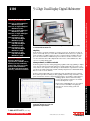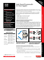
1
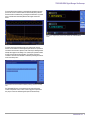
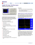
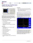
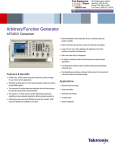
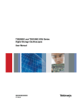
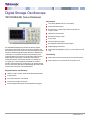
Digital Storage Oscilloscope TBS1000B-EDU Series Datasheet Key features 7 inch WVGA (800X480) Active TFT Color Display 34 automated measurements Dual window FFT, simultaneously monitors both the time and frequency domains Integrated Courseware feature Dual channel frequency counter Zoom Function Autoset and signal auto-ranging New affordable 50 MHz TPP0051 passive probes The TBS1000B-EDU Digital Storage Oscilloscope Series is designed specifically to meet the needs of today's schools and universities. It's the first oscilloscope to use an innovative new Courseware system that enables educators to seamlessly integrate teaching materials onto TBS1000-EDU oscilloscopes. The Courseware information is presented directly on the oscilloscope display and can be used to provide; step by step instructions, background theory, hints and tips or an efficient way for students to document their lab work. The instrument includes a 7-inch WVGA TFT color display, up to 2 GS/s sampling rate, bandwidths from 50 MHz to 200 MHz, dual channel frequency counters and a 5 year standard warranty, just a few of the features that make the TBS1000B-EDU the industry's bestvalue entry level oscilloscope for educational activities. Multiple-language user interface Small footprint and lightweight - Only 4.9 in. (124 mm) deep and 4.4 lb. (2 kg) Connectivity USB 2.0 host port on the front panel for quick and easy data storage USB 2.0 device port on rear panel for easy connection to a PC Key performance specifications 200MHz, 150 MHz, 100 MHz, 70 MHz and 50 MHz bandwidth models 2-channel models Up to 2 GS/s sample rate on all channels 2.5k point record length on all channels Advanced triggers including pulse and line-selectable video triggers www.tektronix.com 1 Datasheet Seeing signal details Critical tools for troubleshooting your device To properly analyze signals you need to make sure that you can see them in enough detail. The TBS1000B-EDU comes standard with a 7-inch high resolution TFT display for a clear view of all of your signals and critical on screen information. The instrument is further enhanced by a user interface inspired by the award winning Tektronix MSO/DPO series of instruments. The interface is easy to use, provides quick access to all of the oscilloscope functions and includes a high resolution "Pan & Zoom" feature enabling you to see even more signal details of up to 10 times normal resolution. The TBS1000B-EDU oscilloscope enables students to learn about the advanced triggers used to debug today's complex circuitry. Standard rising or falling edge, pulse width and video trigger set-ups will allow students to quickly isolate signals of interest and investigate alternative triggering options using the flexible trigger set-up menus. The pulse trigger function can easily capture critical events. The zoom function shows details in an event of up to 10X the normal view. Digital precision for accurate measurements Once signals are captured, the TBS1000B-EDU offers advanced math and measurement capabilities making it easy to evaluate signal quality . Users can quickly add, subtract and multiply waveforms or use any one of 34 automated measurements to quickly and reliably calculate important signal characteristics such as frequency, rise time or overshoot. With up to 200 MHz bandwidth, 2 GS/s maximum sample rate and 3% vertical measurement accuracy the TBS1000B-EDU allows you to see all of your signals details. With the Tektronix proprietary sampling technology there are no compromises, you will get the stated real-time sampling rate on all channels, all the time with at least 10X oversampling. The sampling performance is not reduced when changing horizontal settings or when using multiple channels, enabling you to see the true characteristics of your signals. Quickly analyze signals with the standard 34 automated measurements. See all the details other oscilloscopes might miss with Tektronix proprietary digital realtime sampling. 2 www.tektronix.com TBS1000B-EDU Digital Storage Oscilloscope For advanced frequency analysis, a dedicated front panel button provides quick access to the FFT function that can show both frequency and time domain waveforms simultaneously, providing the student with a convenient way to understand the relationship between their signals and the FFT results. Dual channel - 6 digit frequency counters come standard with all TBS1000B-EDU models. Quickly perform an FFT with a dedicated front panel button. To further enhance the teaching process, the oscilloscopes "Autoset" function can be disabled. For those beginning labs where it is important for a student to learn the basic operation of the oscilloscope, disabling Autoset will help them apply their knowledge of an oscilloscope's operation instead of taking shortcuts with the Autoset button. This feature is password controlled so Autoset can be disabled or enabled by accessing the Autoset screen in the Utility menu. The "Autoset" function can be disabled or enabled by entering a password in the Utility menu. The TBS1000B-EDU also comes with built-in dual channel frequency counters. Independent control of each counter's trigger level provides an easy way to monitor two different signal frequencies simultaneously. www.tektronix.com 3 Datasheet Courseware feature The innovative Courseware feature sets up an education ecosystem by combining powerful PC Course Editor software with the TBS1000B-EDU instruments and a Courseware landing page. The new feature gives educators the ability to create lab descriptions and instructions and then upload the material directly onto a TBS1000-EDU oscilloscope. Existing labs can be modified with content that directly supports recent lectures or explores new ideas discovered in class discussions. Students can perform their lab work directly on the oscilloscope and record their progress in a report file consisting of oscilloscope screen captures. Courseware materials can easily be shared between different labs, professors at the same institution or even between educators from around the world. The Tektronix Courseware Web Page is set up to make it easy for educators to share their own course material or get inspired by reviewing new and interesting ideas from their peers. The Courseware PC interface uses Labs to build courses. The courses are then used to build packages which are uploaded to the oscilloscope. PC Course Editor software The oscilloscope courseware features It all starts with the PC Courseware editor tool. This Windows based application provides the framework in which the courseware is developed. With simple Windows tools instructors can create new labs or edit existing labs using text, images, formulas or tables. A profile signature can also be created that identifies the professor, class or school. When the workspace file is loaded onto an instrument, students can easily access the content by using the dedicated "Course" button located on the front panel. Using the oscilloscopes soft keys and the multipurpose knob, students can access up to 8 courses which can have up to 30 labs each. To accommodate situations where and instrument is used for several classes, up to 100 MB of course material can be stored on the oscilloscope. Once a lab is chosen, the student is able to review the overview section, perform the lab using the step-by-step procedure, collect data, check & save the data results and generate reports that show the waveforms created for each step in the procedure. And all of this work can be done directly on the oscilloscope. The basic building block of the Courseware content is the Lab section. An overview, equipment set-ups, theory discussions and step by step instructions can all be included in this section. When the labs are completed a course can be created. In general, a course is made up of several labs with related topics, for example a basic digital course may consist of lab topics that include; "Basic Boolean Logic", "Simple AND & OR Gates", "Clocks", "Metastable Devices", "Memory Devices", etc. Individual Labs can be shared among multiple courses enabling professors to cater course material to a specific audience. Once all of the courses are defined a package/workspace file is created which contains all of the courses with their related labs and enables the content to be uploaded onto a TBS1000-EDU oscilloscope. To accommodate regional differences the Courseware PC software and the help wizard support is available in 11 different languages. 4 www.tektronix.com TBS1000B-EDU Digital Storage Oscilloscope Designed to make your work easy The TBS1000B-EDU series oscilloscopes are designed with the ease of use and familiar operation you have come to expect from Tektronix. Intuitive operation The intuitive user interface with dedicated per-channel vertical controls, zoom/magnifier button and convenient access to functions using the oscilloscope's soft keys and multi-purpose knob make these instruments easy to use, reducing learning time and increasing efficiency. Help when you need it where you need it The Courseware menus accessed by the oscilloscope soft keys provide easy access to all of the Courseware features. Tektronix Courseware landing page To help educators find new and interesting ideas for creating content for their labs Tektronix has created a Courseware Web page. At this site, users can download and customize relevant course material or upload material to share their own labs with peers. The site also contains a comprehensive search engine that allows visitors to search for labs by key word, author, category, topic and/or language. Although registration for the site is required, once registered, users are able to download or upload material and they will also be able to comment on material that they've used. The context-sensitive help system provides important information specific to the task you are working on. The built-in Help menu provides you with important information about your oscilloscope's features and functions. Help is provided in the same languages as the user interface. Performance you can count on In addition to industry-leading service and support, every TBS1000B-EDU series oscilloscope comes backed with a standard 5-year warranty. A powerful search engine makes is easy to find material of interest. www.tektronix.com 5 Datasheet Specifications All specifications apply to all models unless noted otherwise. Model overview TBS1052B-EDU TBS1072B-EDU TBS1102B-EDU TBS1152B-EDU TBS1202B-EDU Bandwidth 50 MHz 70 MHz 100 MHz 150 MHz 200 MHz Channels 2 2 2 2 2 Sample rate on each channel 1.0 GS/s 1.0 GS/s 2.0 GS/s 2.0 GS/s 2.0 GS/s Record length 2.5k points at all-time bases Vertical system – Analog channels Vertical resolution 8 bits Input sensitivity range 2 mV to 5 V/div on all models with calibrated fine adjustment DC gain accuracy ±3%, from 10 mV/div to 5 V/div Maximum input voltage 300 VRMS CAT II; derated at 20 dB/decade above 100 kHz to 13 Vp-p AC at 3 MHz and above Offset range 2 mV to 200 mV/div: ±1.8 V >200 mV to 5 V/div: ±45 V Bandwidth limit 20 MHz Input coupling AC, DC, GND Input impedance 1 MΩ in parallel with 20 pF Vertical zoom Vertically expand or compress a live or stopped waveform Horizontal system — Analog channels Time base range 2.5 ns to 50 s/div Time base accuracy 50 ppm Horizontal zoom Horizontally expand or compress a live or stopped waveform 6 www.tektronix.com TBS1000B-EDU Digital Storage Oscilloscope Input/Output ports USB interface USB host port on front panel supports USB flash drives USB device port on back of instrument supports connection to PC GPIB interface Optional Data storage Nonvolatile storage Reference waveform display 2.5K point reference waveforms Waveform storage without USB flash drive 2.5K point Maximum USB flash drive size 64 GB Waveform storage with USB flash drive 96 or more reference waveforms per 8 MB Setups without USB flash drive 10 front-panel setups Setups with USB flash drive 4000 or more front-panel setups per 8 MB Screen images with USB flash 128 or more screen images per 8 MB (the number of images depends on file format selected) drive Save All with USB flash drive 12 or more Save All operations per 8 MB A single Save All operation creates 3 to 9 files (setup, image, plus one file for each displayed waveform) Course content 100 MB Acquisition system Acquisition modes Peak Detect High-frequency and random glitch capture. Captures glitches as narrow as 12 ns (typical) at all time base settings from 5 μs/div to 50 s/div Sample Sample data only Average Waveform averaged, selectable: 4, 16, 64, 128 Single Sequence Use the Single Sequence button to capture a single triggered acquisition sequence Roll At acquisition time base settings of >100 ms/div Trigger system External trigger input Included on all models Trigger modes Auto, Normal, Single Sequence Trigger types Edge (Rising/Falling) Conventional level-driven trigger. Positive or negative slope on any channel. Coupling selections: AC, DC, Noise Reject, HF Reject, LF Reject Video Trigger on all lines or individual lines, odd/even or all fields from composite video, or broadcast standards (NTSC, PAL, SECAM) Pulse Width (or Glitch) Trigger on a pulse width less than, greater than, equal to, or not equal to, a selectable time limit ranging from 33 ns to 10 s Trigger source Two channel models: CH1, CH2, Ext, Ext/5, AC Line Trigger view Displays trigger signal while Trigger View button is depressed. Trigger signal frequency readout Provides a frequency readout of the trigger source. www.tektronix.com 7 Datasheet Waveform measurements Cursors Types Amplitude, Time Measurements ΔT, 1/ΔT, ΔV Automatic measurements Period, Frequency, Pos Width, Neg Width, Rise Time, Fall Time, Maximum , Minimum , Peak-Peak, Mean, RMS, Cycle RMS, Cursor RMS, Phase, Pos Pulse Cnt, Neg Pulse Cnt, Rise Edge Cn, Fall Edge Cn, Pos Duty, Neg Duty, Amplitude, Cycle Mean, Cursor Mean, Burst Width, Pos Overshoot, Neg Overshoot, Area, Cycle Area, High, Low, Delay RR, Delay RF, Delay FR, Delay FF Waveform math Arithmetic Add, Subtract, Multiply Math functions FFT FFT Windows: Hanning, Flat Top, Rectangular 2048 sample points Sources Two channel models: CH1 - CH2, CH2 - CH1, CH1 + CH2, CH1 × CH2 Autoset menu Single-button, automatic setup of all channels for vertical, horizontal, and trigger systems, with undo autoset. Square wave Single cycle, multicycle, rising or falling edge Sine wave Single cycle, multicycle, FFT spectrum Video (NTSC, PAL, SECAM) Field: All, Odd, or Even Line: All or Selectable Line Number Autorange Automatically adjust vertical and/or horizontal oscilloscope settings when probe is moved from point to point, or when the signal exhibits large changes. Frequency counter Resolution 6 digits Accuracy (typical) + 51 parts per million including all frequency reference errors and +1 count errors Frequency range AC coupled, 10 Hz minimum to rated bandwidth Frequency counter signal source Pulse width or edge selected trigger source Frequency counter measures selected trigger source at all times in pulse width and edge mode, including when the oscilloscope acquisition is halted due to changes in run status, or acquisition of a single shot event has completed. The frequency counter does not measure pulses that do not qualify as legitimate trigger events. Pulse Width mode: Counts pulses of enough magnitude inside the 250 ms measurement window that qualify as triggerable events (e.g. all narrow pulses in a PWM pulse train if set to "<" mode and the limit is set to a relatively small number). Edge Trigger mode: Counts all pulses of enough magnitude. Channels 8 www.tektronix.com 2 channel TBS1000B-EDU Digital Storage Oscilloscope Display system Interpolation Sin (x)/x Waveform styles Dots, vectors Persistence Off, 1 s, 2 s, 5 s, infinite Format YT and XY Courseware software System requirements The following PC configuration represents the minimum requirements needed to install the Courseware software. Operating System Windows XP, Windows 7, Windows 8, Linux (ubuntu 12.04, 12.10, 13.04 or fedora 18, 19) RAM 512 Megabytes (MB) Disk space 1 Gigabyte of available hard disk space Display XVGA 1024×768 with 120 dpi font size recommended Removable media CD-ROM or DVD drive Peripherals Keyboard and Microsoft mouse or other compatible pointing device Physical characteristics Dimensions mm in. Height 158.0 6.22 Width 326.3 12.85 Depth 124.2 4.89 mm in. Height 266.7 10.5 Width 476.2 18.75 Depth 228.6 9.0 Shipping dimensions Weight kg lb. Instrument only 2.0 4.3 ...with accessories 2.2 4.9 RM2000B rackmount mm in Width 482.6 19.0 Height 177.8 7.0 Depth 108.0 4.25 www.tektronix.com 9 Datasheet Environmental Temperature Operating 0 to +50 ºC Nonoperating –40 to +71 ºC Humidity Operating and nonoperating Up to 85% RH at or below +40 ºC Up to 45% RH up to +50 ºC Altitude Operating and nonoperating Up to 3,000 m (9,843 ft.) Regulatory Electromagnetic compatibility Meets Directive 2004/108/EC, EN 61326-2-1 Class A; Australian EMC Framework Safety UL61010-1:2004, CSA22.2 No. 61010-1:2004, EN61010-1:2001, IEC61010-1:2001 10 www.tektronix.com TBS1000B-EDU Digital Storage Oscilloscope Ordering information Models TBS1052B-EDU 50 MHz, 2 Ch, 1 GS/s, TFT DSO TBS1072B-EDU 70 MHz, 2 Ch, 1 GS/s, TFT DSO TBS1102B-EDU 100 MHz, 2 Ch, 2 GS/s, TFT DSO TBS1152B-EDU 150 MHz, 2 ch, 2 GS/s, TFT DSO TBS1202B-EDU 200 MHz, 2 ch, 2 GS/s, TFT DSO Instrument options Language options Opt. L1 French overlay Opt. L2 Italian overlay Opt. L3 German overlay Opt. L4 Spanish overlay Opt. L5 Japanese overlay Opt. L6 Portuguese overlay Opt. L7 Simplified Chinese overlay Opt. L8 Traditional Chinese overlay Opt. L9 Korean overlay Opt. L10 Russian overlay Power plug options Opt. A0 North America power plug (115 V, 60 Hz) Opt. A1 Universal Euro power plug (220 V, 50 Hz) Opt. A2 United Kingdom power plug (240 V, 50 Hz) Opt. A3 Australia power plug (240 V, 50 Hz) Opt. A4 North America power plug (240 V, 50 Hz) Opt. A5 Switzerland power plug (220 V, 50 Hz) Opt. A6 Japan power plug (100 V, 110/120 V, 60 Hz) Opt. A10 China power plug (50 Hz) Opt. A11 India power plug (50 Hz) Opt. A12 Brazil power plug (60 Hz) Opt. A99 No power cord www.tektronix.com 11 Datasheet Service options Opt. D1 Calibration Data Report Probes and accessories are not covered by the oscilloscope warranty and Service Offerings. Refer to the datasheet of each probe and accessory model for its unique warranty and calibration terms. Probe option TBS1XX2B-EDU P2220 Replaces standard probes with P2220 probes (200 MHz passive voltage probes with 1x/ 10x attenuation) Accessories Standard accessories Accessory Description Passive probes, one per channel TPP0051: 50MHz passive probe for: TBS1052B-EDU TPP0101: 100 MHz passive probe for: TBS1072B-EDU, TBS1102B-EDU TPP0201: 200 MHz passive probe for: TBS1152B-EDU, TBS1202B-EDU Power cord (Please specify plug option) NIM/NIST Traceable certificate of calibration Printed documentation Installation and safety manual (English, Japanese, and Simplified Chinese) CD with customer documentation Customer documentation including detailed user manuals (English, French, German, Italian, Japanese, Korean, Portuguese, Russian, Simplified Chinese, Spanish, Traditional Chinese) Education CD Courseware PC Software, example Courseware labs, ABC's of Probes application note, XYZ's of Oscilloscopes application note, Courseware PC Software download link, www.tek.com Education landing page 5-year warranty Covers labor and parts for defects in materials and workmanship for 5 years, excluding probes and accessories (probes and accessories are not covered by the oscilloscope warranty and service offerings. refer to the data sheet of each probe and accessory model for its unique warranty and calibration terms) Recommended accessories Accessory Description TEK-USB-488 GPIB-to-USB converter AC2100 Soft carrying case for instrument HCTEK4321 Hard plastic carrying case for instrument (requires AC2100) RM2000B Rackmount kit 077-0444-xx Programmer manual – English only 077-0897-xx Service manual – English only 174-4401-xx USB host to device cable, 3 ft. long 12 www.tektronix.com TBS1000B-EDU Digital Storage Oscilloscope Recommended probes Probe Description TPP0051 10X passive probe, 50 MHz bandwidth TPP0101 10X passive probe, 100 MHz bandwidth TPP0201 10X passive probe, 200 MHz bandwidth P2220 1X/10X passive probe, 200 MHz bandwidth P6101B 1X passive probe (15 MHz, 300 V RMS CAT II rating) P6015A 1000X high-voltage passive probe (75 MHz) P5100A 100X high-voltage passive probe (500 MHz) P5200A 50 MHz, 50X/500X high-voltage differential probe P6021A 15 A, 60 MHz AC current probe P6022 6 A, 120 MHz AC current probe A621 2000 A, 5 to 50 kHz AC current probe A622 100 A, 100 kHz AC/DC current probe/BNC TCP303/TCPA300 150 A, 15 MHz AC/DC current probe/amplifier TCP305A/TCPA300 50 A, 50 MHz AC/DC current probe/amplifier TCP312A/TCPA300 30 A, 100 MHz AC/DC current probe/amplifier TCP404XL/TCPA400 500 A, 2 MHz AC/DC current probe/amplifier Tektronix is registered to ISO 9001 and ISO 14001 by SRI Quality System Registrar. Product(s) complies with IEEE Standard 488.1-1987, RS-232-C, and with Tektronix Standard Codes and Formats. www.tektronix.com 13 Datasheet ASEAN / Australasia (65) 6356 3900 Belgium 00800 2255 4835* Central East Europe and the Baltics +41 52 675 3777 Finland +41 52 675 3777 Hong Kong 400 820 5835 Japan 81 (3) 6714 3010 Middle East, Asia, and North Africa +41 52 675 3777 People's Republic of China 400 820 5835 Republic of Korea 001 800 8255 2835 Spain 00800 2255 4835* Taiwan 886 (2) 2722 9622 * European toll-free number. If not accessible, call: +41 52 675 3777 Austria 00800 2255 4835* Brazil +55 (11) 3759 7627 Central Europe & Greece +41 52 675 3777 France 00800 2255 4835* India 000 800 650 1835 Luxembourg +41 52 675 3777 The Netherlands 00800 2255 4835* Poland +41 52 675 3777 Russia & CIS +7 (495) 6647564 Sweden 00800 2255 4835* United Kingdom & Ireland 00800 2255 4835* Balkans, Israel, South Africa and other ISE Countries +41 52 675 3777 Canada 1 800 833 9200 Denmark +45 80 88 1401 Germany 00800 2255 4835* Italy 00800 2255 4835* Mexico, Central/South America & Caribbean 52 (55) 56 04 50 90 Norway 800 16098 Portugal 80 08 12370 South Africa +41 52 675 3777 Switzerland 00800 2255 4835* USA 1 800 833 9200 Updated 10 April 2013 For Further Information. Tektronix maintains a comprehensive, constantly expanding collection of application notes, technical briefs and other resources to help engineers working on the cutting edge of technology. Please visit www.tektronix.com. Copyright © Tektronix, Inc. All rights reserved. Tektronix products are covered by U.S. and foreign patents, issued and pending. Information in this publication supersedes that in all previously published material. Specification and price change privileges reserved. TEKTRONIX and TEK are registered trademarks of Tektronix, Inc. All other trade names referenced are the service marks, trademarks, or registered trademarks of their respective companies. 22 Jan 2014 www.tektronix.com 3GW-30001-0 Arbitrary/Function Generator AFG2021 Data Sheet Features & Benefits 20 MHz sine wave, 10 MHz square and pulse wave provides a cost-effective solution for most applications 250 MS/s sampling rate and 14-bit vertical resolution provide best-in-class signal fidelity The intuitive and AFG3000-like UI shorten the learning curve and customers’ time to market 4 × 128 kS built-in and USB memory expansion for user-defined arbitrary waveforms Standard USB host/device, optional GPIB and LAN interfaces keep the best balance between cost and versatility Multiple run modes and modulation modes cover most customer requirements to finish the job Menu and online help are in 8 languages 2U height and half-rack width fit both benchtop and rack-mounted applications Free ArbExpress makes user-defined waveform editing and downloading extremely easy Free SignalExpress combines Tektronix bench instruments into a low-cost solution for automatic testing Applications Electronic test and design Sensor simulation Education and training Functional test System integration Data Sheet Superior Performance at an Affordable Price Nearly all consumer products today have circuits or devices that require the input of specific electronic signals in order for the product to perform correctly. These signals can be as simple as an audio frequency or clock signal or more complex such as a serial data stream or signal from an airbag sensor during a crash. With 20 MHz bandwidth, 14-bit resolution, and 250 MS/s sample rate, the AFG2021 Arbitrary Function Generator can create both simple and complex signals at an entry-level price. With 12 standard waveforms, modulation capability, and a built-in noise generator you can quickly create the signal you need to thoroughly exercise your designs. Intuitive User Interface Inherited from the AFG3000 The innovative ease-of-use features first seen on the AFG3000 Series arbitrary/function generators are the building blocks for the AF2021, providing quick access to setup and operational features. Additionally, AFG3000 customers can easily migrate to the new AFG2021 without having to learn a new UI. To easily see waveform information, a 3.5 in. color TFT screen shows relevant parameters in both graphic and text formats, which gives users full confidence in their settings, and lets them focus on the task at hand. The front-panel shortcut buttons and rotary knob allow access to the most frequently used functions and settings with minimum effort and time. 2 www.tektronix.com Frequency range from 1 μHz to 20 MHz, fits for most amplifier and filter testing cases. Efficient Shortcuts to High Frequency Traditional function generators created their output signals using analog oscillators and signal conditioning. The Tektronix AFG2021 relies on Direct Digital Synthesis (DDS) techniques to determine the rate at which samples are clocked out of their memory. DDS technology synthesizes waveforms by using a single clock frequency to spawn any frequency within the instrument’s range. DDS architecture provides exceptional frequency agility, making it easy to program both frequency and phase changes on the fly, which is useful to test any type of frequency-related DUT – radio and satellite system components, amplifiers, or filters for example. Arbitrary/Function Generator — AFG2021 Increase Productivity with SignalExpress Every AFG2021 ships with a free copy of the Limited Tektronix Edition of National Instrument’s LabVIEW SignalExpress for basic instrument control, data logging, and analysis. SignalExpress supports the range of Tektronix bench instruments enabling you to connect your entire test bench. You can then access the feature-rich tools packed into each instrument from one intuitive software interface. This allows you to automate complex measurements requiring multiple instruments, log data for an extended period of time, time-correlate data from multiple instruments, and easily capture and analyze your results, all from your PC. Only Tektronix offers a connected test bench of intelligent instruments to simplify and speed debug of your complex design. Connectivity ArbExpress makes real-world signal replication almost with no effort. ArbExpress® Makes Real-world Waveform Replication with Minimum Efforts With the ArbExpress software, you can quickly create waveforms that can be transferred to the AFG2021 to meet custom stimulus requirements. ArbExpress supports direct connection to Tektronix oscilloscopes and AFGs through USB, GPIB, or LAN. With the software, users can import real-world signals captured with an oscilloscope onto a PC, then edit and download them onto an AFG to replicate the captured waveform. This is extremely useful for automotive, medical, and industrial applications where recreating sensor data is critical to analyzing the integrity of the design. Using the USB host socket, users can save their customized waveforms or instrument settings onto a USB memory stick. Reloading the data is easily done by plugging the device back into the USB host socket. The USB connector and optional GPIB/LAN functionality offers a way for users to connect the instrument to a PC for waveform download and remote control. Compact Form Factor The 2U height and half-rack width form factor enables the AFG2021 to be stacked on other bench instruments, such as digital multimeters, power supplies, and frequency counters, saving valuable bench space. Together with the standard RMU2U rackmount kit, GPIB interface, and full SCPI support the AFG2021 is also a perfect option for rackmount applications, such as ATE configuration in manufacturing environments. www.tektronix.com 3 Data Sheet Characteristics General Characteristic Description Channels Waveforms 1 Sine, Square, Pulse, Ramp, Noise, DC, Sin(x)/x, Gaussian, Lorentz, Exponential Rise, Exponential Decay, and Haversine 1 μHz to 20 MHz 1 μHz to 10 MHz Sine Wave Sine Wave in Burst Mode 20 MHz Effective Maximum Frequency Out Amplitude Flatness (1 Vp-p) <5 MHz ±0.15 dB 5 MHz to 20 MHz ±0.3 dB Harmonic Distortion (1 Vp-p) 10 Hz to 20 kHz <–70 dBc 20 kHz to 1 MHz <–60 dBc 1 MHz to 10 MHz <–50 dBc 10 MHz to <–40 dBc 20 MHz THD <0.2% (10 Hz to 20 kHz, 1 Vp-p) Spurious (1 Vp-p) 10 Hz to 1 MHz <–60 dBc 1 MHz to 20 MHz <–50 dBc Phase Noise, 20 MHz: <–110 dBc/Hz at 10 kHz offset, 1 Vp-p Typical Residual Clock –63 dBm Noise 1 μHz to 10 MHz Square Wave ≤18 ns Rise/Fall Time <500 ps Jitter (RMS), Typical Ramp Wave 1 μHz to 200 kHz Linearity ≤0.1% of peak output at 10% to 90% of amplitude range Symmetry 0.0% to 100.0% Pulse Wave 1 mHz to 10 MHz Pulse Width 30.00 ns to 999.99 s Resolution 10 ps or 5 digits Pulse Duty 0.001% to 99.999% (Limitations of pulse duty width apply) Edge Transition 18 ns to 0.625 × Pulse Period Time Resolution 10 ps or 4 digits Lead Delay Range Continuous Mode: 0 ps to Period Trigger/Gate Burst Mode: 0 ps to Period – [Pulse Width + 0.8 × (Leading Edge Time + Trailing Edge Time)] Resolution 10 ps or 8 digits Overshoot, <5% Typical <500 ps Jitter (RMS), Typical 4 www.tektronix.com Characteristic Description Other Waveforms Noise Bandwidth (–3 dB) Noise Type DC (into 50 Ω) Arbitrary Waveforms Arbitrary Waveforms in Burst Mode Effective Analog Bandwidth (–3 dB) Nonvolatile Memory Memory: Sample Rate Vertical Resolution Rise/Fall Time Jitter (RMS) Amplitude, 50 Ω Load Amplitude, Open Circuit Accuracy 1 μHz to 200 kHz 20 MHz Resolution Units Output Impedance Load Impedance Setting Isolation Short-circuit Protection External Voltage Protection DC Offset Range, 50 Ω Load DC Offset Range, Open Circuit Accuracy Resolution White Gaussian –5 V to +5 V 1 mHz to 10 MHz 1 mHz to 5 MHz 34 MHz 4 waveforms 2 to 128k: 250 MS/s 14 bits ≤20 ns 4 ns 10 mVp-p to 10 Vp-p 20 mVp-p to 20 Vp-p ±(1% of setting + 1 mV), (1 kHz sine waveform, 0 V offset, >10 mVp-p amplitude) 0.1 mVp-p, 0.1 mVRMS, 1 mV, 0.1 dBm, or 4 digits Vp-p, VRMS, dBm (sine wave only) 50 Ω Selectable: 50 Ω, 1 Ω to 10.0 kΩ, High Z (adjusts displayed amplitude according to selected load impedance) <42 VPeak maximum to earth Signal outputs are robust against permanent shorts against floating ground To protect signal outputs against external voltages use fuse adapter 013-0345-00 ±(5 VPeak – amplitude Vp-p/2) ±(10 VPeak – amplitude Vp-p/2) ±(1% of |setting| + 5 mV + 0.5% of amplitude (Vp-p)) 1 mV Arbitrary/Function Generator — AFG2021 Modulation Burst AM, FM, PM Characteristic Description Carrier Waveforms Source Internal Modulating Waveform Internal Modulating Frequency AM Modulation Depth Min FM Peak Deviation Max FM Peak Deviation All, including ARB, except Pulse, Noise, and DC Internal/External Sine, Square, Ramp, Noise, ARB (AM: Maximum waveform length 4,096; FM/PM: Maximum waveform length 2,048) 2 mHz to 50.00 kHz Characteristic Description Waveforms Type Internal Trigger Rate Gate and Trigger Sources All, including ARB, except Noise and DC Triggered, Gated (1 to 1,000,000 cycles or Infinite) 1 μs to 500.0 s Internal, External, Manual Trigger, and Remote Interface Auxiliary Input 0.0% to +120.0% Modulation Input DC Characteristic Description Input Range All except FSK: ±1 V full scale FSK: 3.3 V logic level 10 kΩ DC to 25 kHz (122 kS/s sample rate) 10 MHz Frequency Shift Keying Impedance Frequency Range Characteristic Description External Triggered/Gated Burst Input Carrier Waveforms Source Internal Modulating Frequency Number of Keys All, including ARB, except Pulse, Noise, and DC Internal/External 2 mHz to 1.000 MHz Characteristic Description Level Pulse Width Slope Trigger Delay Resolution Jitter (RMS), Typical TTL compatible 100 ns minimum Positive/Negative selectable 0.0 ns to 85.000 s 100 ps or 5 digits Burst: <500 ps (Trigger input to signal output) 2 Pulse Width Modulation Characteristic Description Carrier Waveform Source Internal Modulating Waveform Internal Modulating Frequency Deviation Pulse Internal/External Sine, Square, Ramp, Noise, ARB (Maximum waveform length 2,048) 2 mHz to 50.00 kHz 0% to 50.0% of pulse period 10 MHz Reference Input Characteristic Description Impedance Required Input Voltage Swing Lock Range 1 kΩ, AC coupled 100 mVp-p to 5 Vp-p 10 MHz ±35 kHz Auxiliary Output Sweep Characteristic Description Waveforms Type Sweep Time Hold/Return Time Max Total Sweep Time (Sweep + Hold + Return) Resolution Total Sweep Time Accuracy, Typical Min Start/Stop Frequency Max Start/Stop Frequency All, including ARB, except Pulse, Noise, and DC Linear, Logarithmic 1 ms to 300 s 0 ms to 300 s 300 s Trigger Output Characteristic Description Level Impedance Jitter (RMS), Typical Max Frequency Positive TTL level pulse into 1 kΩ 50 Ω 500 ps 4.9 MHz (4.9 MHz to 20 MHz: A fraction of the frequency is output) 1 ms or 4 digits 0.4% All except ARB: 1 μHz ARB: 1 mHz Sine: 20 MHz Square: 10 MHz ARB: 10 MHz Others: 200 kHz www.tektronix.com 5 Data Sheet Common Characteristics Environmental and Safety Characteristics Remote Programming (GPIB, LAN 10BASE-T/100BASE-TX, USB 1.1, compatible with SCPI-1999.0 and IEEE 488-2 standards) Characteristic USB LAN*1 Function Change Frequency Change Amplitude Change Select User ARB Data Download Time for 4k Point ARB Waveform Data (8 KB), Typical 95 ms 2 ms 60 ms 88 ms 20 ms 103 ms 19 ms 67 ms 120 ms 84 ms GPIB*1 84 ms 2 ms 52 ms 100 ms 42 ms *1 GPIB and LAN interfaces are only available on the instrument with Option GL. Characteristic Temperature Operating Nonoperating Humidity Operating Nonoperating Altitude Operating Nonoperating EMC Compliance Safety General Characteristic Description Frequency Setting 1 μHz or 12 digits Resolution Phase (except DC, Noise, Pulse) Range –360° to +360° Resolution Sine: 0.01° Other Waveforms: 0.1° Internal Noise Add When activated, output signal amplitude is reduced to 50% Level 0.0% to 50% of amplitude (Vp-p) setting Resolution 1% Main Output 50 Ω Effective Frequency 2 ms through remote control Switching Speed Internal Frequency Reference Stability All except ARB: ±1 ppm, 0 °C to 50 °C ARB: ±1 ppm, ±1 μHz, 0 °C to 50 °C Aging ±1 ppm per year 100 V to 240 V, 50 Hz to 60 Hz or 115 V, 400 Hz Power Source Power Consumption 60 W Warm-up Time, 20 minutes Typical <10 s Power On Self Diagnostics, Typical Acoustic Noise, <50 dBA Typical Display 3.5 in. Color TFT LCD User Interface and English, French, German, Japanese, Korean, Simplified and Help Language Traditional Chinese, Russian (User selectable) Physical Characteristics Benchtop Configuration Dimension mm in. Height Weight Depth 104.2 241.8 419.1 4.10 9.52 16.50 Weight kg lb. Net Shipping 2.87 4.72 6.3 10.4 6 www.tektronix.com Description 0 °C to +50 °C –30 °C to +70 °C ≤80%, +0 °C to +40 °C, noncondensing ≤60%, +40 °C to +50 °C, noncondensing 5% to 90%, <+40 °C, noncondensing 5% to 80%, ≥+40 °C to ≤+60 °C, noncondensing 5% to 40%, >+60 °C to ≤+70 °C, noncondensing Up to 3,000 m (9,842 ft.) Up to 12,000 m (39,370 ft.) EU Council Directive 2004/108/EC UL61010-1; 2004 CAN/CSA C22.2 No. 61010-1; 2004 EN61010-1; 2001 IEC61010-1; 2001 Ordering Information AFG2021 Arbitrary/Function Generator. Includes: User Manual, Power Cord, USB Cable, CD-ROM with Programmer Manual, Service Manual, Labview and IVI Drivers, CD-ROM with ArbExpress® Software, NIST-traceable Calibration Certificate. Please specify power cord and local language for user manual when ordering. Configuration Options Option Description Opt. GL GPIB and LAN interfaces Language Options Option Description Opt. Opt. Opt. Opt. Opt. Opt. Opt. Opt. Opt. Opt. Opt. Opt. English manual French manual Italian manual German manual Spanish manual Japanese manual Portuguese manual Simplified Chinese manual Traditional Chinese manual Korean manual Russian manual No manual L0 L1 L2 L3 L4 L5 L6 L7 L8 L9 L10 L99 Arbitrary/Function Generator — AFG2021 Power Plug Options Recommended Accessories Option Description Accessory Description Opt. Opt. Opt. Opt. Opt. Opt. Opt. Opt. Opt. Opt. North America power Universal Euro power United Kingdom power Australia power Switzerland power Japan power China power India power Brazil power No power cord or AC adapter RMU2U 013-0345-00 159-0454-00 012-0482-00 012-1256-00 012-0991-00 011-0049-02 Rackmount kit Fuse adapter, BNC-P to BNC-R Fuse set, 3 pcs, 0.125 A BNC cable shielded, 3 ft. BNC cable shielded, 9 ft. GPIB cable, double shielded 50 Ω BNC terminator A0 A1 A2 A3 A5 A6 A10 A11 A12 A99 Warranty Three-year warranty on parts and labor. Service Options Option Description Opt. Opt. Opt. Opt. Opt. Opt. Opt. Calibration Service 3 Years Calibration Service 5 Years Calibration Data Report Calibration Data Report 3 Years (with Opt. C3) Calibration Data Report 5 Years (with Opt. C5) Repair Service 5 Years Repair Service Coverage 5 Years (starts at time of customer instrument purchase) C3 C5 D1 D3 D5 R5 R5DW www.tektronix.com 7 Data Sheet Contact Tektronix: ASEAN / Australasia (65) 6356 3900 Austria 00800 2255 4835* Balkans, Israel, South Africa and other ISE Countries +41 52 675 3777 Belgium 00800 2255 4835* Brazil +55 (11) 3759 7627 Canada 1 800 833 9200 Central East Europe and the Baltics +41 52 675 3777 Central Europe & Greece +41 52 675 3777 Denmark +45 80 88 1401 Finland +41 52 675 3777 France 00800 2255 4835* Germany 00800 2255 4835* Hong Kong 400 820 5835 India 000 800 650 1835 Italy 00800 2255 4835* Japan 81 (3) 6714 3010 Luxembourg +41 52 675 3777 Mexico, Central/South America & Caribbean 52 (55) 56 04 50 90 Middle East, Asia, and North Africa +41 52 675 3777 The Netherlands 00800 2255 4835* Norway 800 16098 People’s Republic of China 400 820 5835 Poland +41 52 675 3777 Portugal 80 08 12370 Republic of Korea 001 800 8255 2835 Russia & CIS +7 (495) 7484900 South Africa +41 52 675 3777 Spain 00800 2255 4835* Sweden 00800 2255 4835* Switzerland 00800 2255 4835* Taiwan 886 (2) 2722 9622 United Kingdom & Ireland 00800 2255 4835* USA 1 800 833 9200 * European toll-free number. If not accessible, call: +41 52 675 3777 Updated 10 February 2011 For Further Information. Tektronix maintains a comprehensive, constantly expanding collection of application notes, technical briefs and other resources to help engineers working on the cutting edge of technology. Please visit www.tektronix.com Copyright © Tektronix, Inc. All rights reserved. Tektronix products are covered by U.S. and foreign patents, issued and pending. Information in this publication supersedes that in all previously published material. Specification and price change privileges reserved. TEKTRONIX and TEK are registered trademarks of Tektronix, Inc. All other trade names referenced are the service marks, trademarks, or registered trademarks of their respective companies. 31 May 2012 www.tektronix.com 75W-28089-0 5½-Digit Dual-Display Digital Multimeter The Model 2110 5½-Digit Dual-Display Digital Multimeter combines a compelling price with a comprehensive set of capabilities, superior measurement accuracy, and high speed for a broad range of applications. It features 15 measurement functions and 7 math functions and has dual-line display capability, which allows it to display two different measurements concurrently. The Model 2110 is an unbeatable value for production, R&D, and test engineers, scientists, and students making a wide variety of measurements in portable, bench, and system applications. High Accuracy, Abundant Capabilities, Low Cost The Model 2110 provides precision and a rich set of capabilities at a value price. It has 0.012% one-year basic DC voltage accuracy and 0.020% one-year basic resistance accuracy up to the 100kW range. • High accuracy, high speed for general purpose measurements • 15 measurement functions, including capacitance and thermocouple measurements • Dual-line display allows concurrent measurements • TMC-compliant USB 2.0 interface for use with SCPI test commands • GPIB option for use in system applications DIGITAL MULTIMETERS & SYSTEMS • Includes PC software utilities for graphing and data sharing in both Microsoft® Word and Excel • Rugged construction for durability in bench/portable applications • Includes all accessories, such as start-up software, USB cable, power cable, and safety test leads • CE compliant and listed APPLICATIONS Built for Production Testing The Model 2110 Digital Multimeter is ideal for applications in manual, semi-automatic, and automatic testing of low-cost electronic devices, circuits, modules, electrical components, and semiconductor components. Key features include: • Speed: up to 50,000 readings per second • Control: GPIB (optional) and USB interfaces, accepting SCPI (IEEE488.2) commands • External BNC trigger lines • NIST traceability (with included calibration certificate) Built for General Purpose Uses The Model 2110 Digital Multimeter is also ideal for bench uses such as research, development, service, calibration, and teaching. Benchoriented features include: • Accuracy: 0.012% basic DCV accuracy • Easy-to-operate panel • Easy waveform plotting and data collection with KI-Tool and KI-Link • Store up to 2000 readings The Model 2110 provides a wide number of measurement ranges and functions: • DC voltage: 0.1V, 1V, 10V, 100V, and 1000V • AC voltage: 0.1V, 1V, 10V, 100V, and 750V • DC current: 10mA, 100mA, 1A, 3A, and 10A • AC current: 1A, 3A, and 10A • Two- and four-wire resistance: 100W, 1kW, 10kW, 100kW, 1MW, 10MW, and 100MW • Frequency: From 10Hz to 300kHz • Capacitance measurement: 1nF, 10nF, 100nF, 1µF, 10µF, 100µF • Thermocouple measurement: J-, R-, S-, T-, E-, N-, B-, C-, and K-type thermocouples • Temperature (RTD and NTC Thermistor) measurements • Diode measurement • Continuity test • Programmable A-D converter and filter settings for signal to noise optimization. Additionally, seven mathematical operations can be performed on measurement readings: percentage, average, min/max, NULL, limits, mX+b, dB, and dBm testing. Speed At 5½ digits, the Model 2110 delivers up to 200 readings/s via the USB remote interface. At the fast 4½-digit setting, it reads up to 50,000 readings/s and up to 30,000 readings/s into the buffer, making it ideal for production and monitoring applications in which speed is critical. 1.888.KEITHLEY (U.S. only) www.keithley.com A Greater Measure of Confidence Low-cost 5½-digit DMM for system, bench, or portable applications Low-cost 5½-digit DMM for system, bench, or portable applications 2110 2110 5½-Digit Dual-Display Digital Multimeter Accessories Supplied Reference Manual on CD, Specifications, LabVIEW® Driver, Keithley I/O Layer, USB Cable, Power Cable, Safety Test Leads, KI-Tool, and KI-Link Add-in (both Microsoft Word and Excel versions), Calibration Certificate All accessories, such as start-up software, USB cable, power cable, and safety test leads, are included with the Model 2110. Simplicity The Model 2110 is operational and intuitive to use right out of the box. The functions on the front panel are user friendly and easy to read. Its KI-Tool and KI-Link software allow users to quickly control the instrument over GPIB (if equipped) or USB, record measurements, and display time-series plots of the data. Its LabView® and IVI drivers give more-advanced customers even more control over the instrument. Both the TMC-compliant USB remote interface and the GPIB interface allow easy re-use of existing SCPI programs. Startup Software, PC Utilities Included The KI-Tool application provides charting and graphing capabilities without programming to simplify setup, checkout, and basic measurement applications requiring graphical data representation. Scale, offset, and level can be adjusted to fine-tune images for visual evaluation of signal and noise elements over time. It also includes tabular data and SCPI command prompt windows for maximum flexibility. Data sets can also be saved to disk files. Low-cost 5½-digit DMM for system, bench, or portable applications 2110-100: 5½-digit USB Digital Multimeter (100V) 2110-120: 5½-digit USB Digital Multimeter (120V) 2110-220: 5½-digit USB Digital Multimeter (220V) 2110-240: 5½-digit USB Digital Multimeter (240V) 2110-100-GPIB: 5½-digit USB and GPIB Digital Multimeter (100V) 2110-120-GPIB: 5½-digit USB and GPIB Digital Multimeter (120V) 2110-220-GPIB: 5½-digit USB and GPIB Digital Multimeter (220V) 2110-240-GPIB: 5½-digit USB and GPIB Digital Multimeter (240V) The Microsoft Excel Add-In utility is also included and provides quick data import into a standard Microsoft Excel spreadsheet, including selectable graphing, instrument settings, and number of data points collected. Data can then be analyzed through standard or optional Microsoft Excel functions, including graphical, statistical, and trend charting. A version supporting Microsoft Word is also included for direct data import into reports. LabView, IVI-C, and IVI-COM drivers are also supplied to allow for increased flexibility in integrating the Model 2110 into new and existing systems and test routines. KI-Tool simplifies basic measurement applications through every setup and graphical data representation. 1.888.KEITHLEY (U.S. only) www.keithley.com A Greater Measure of Confidence DIGITAL MULTIMETERS & SYSTEMS Low-cost 5½-digit DMM for system, bench, or portable applications Ordering Information 2110 5½-Digit Dual-Display Digital Multimeter Specifications DC CHARACTERISTICS Model 2110 specifications Range 100.000 mV 1.00000 V 10.0000 V 100.000 V 1000.00 V Accuracy1 ±(% of reading + % of range) Input Resolution Resistance 1 Year, 23° ±5°C 1 µV 0.012 + 0.004 10 µV 0.012 + 0.001 0.1 mV 0.012 + 0.002 10 MW 1 mV 0.012 + 0.002 10 mV 0.02 + 0.003 DCI (DC Current) Range 10.0000 mA 100.000 mA 1.00000 A 3.0000 A 10.0000 A Accuracy1 ±(% of reading + % of range) Shunt Resolution Resistance 1 Year, 23° ±5°C 0.1 µA 0.05 + 0.020 5.1 W 1 µA 0.05 + 0.010 5.1 W 10 µA 0.150 + 0.020 0.1 W 100 µA 0.200 + 0.030 0.1 W 100 µA 0.250 + 0.050 5 mW Resistance 2 Range 100.000 W 1.00000kW 10.0000kW 100.000kW 1.00000MW 10.0000MW 100.000MW Resolution 1mW 10mW 100mW 1 W 10W 100 W 1 kW Range 1.0000V Resolution 10 µV Test Current 1 mA 1 mA 100 µA 10 µA 1 µA 0.1 µA 0.1 µA Test Current 1 mA Accuracy1 ±(% of reading + % of range) 1 Year, 23° ±5°C 0.020 + 0.030 Temperature Coefficient 0°–18°C & 28°–40°C 0.002 + 0.0005 Test Current 1 mA Accuracy1 ±(% of reading + % of range) 1 Year, 23° ±5°C 0.020 + 0.020 Temperature Coefficient 0°–18°C & 28°–40°C 0.002 + 0.0005 Continuity Range 1000W Resolution 10 mW Temperature Coefficient 0°–18°C & 28°–40°C 0.005 + 0.002 0.005 + 0.001 0.008 + 0.001 0.008 + 0.001 0.008 + 0.001 Accuracy1 ±(% of reading + % of range) 1 Year, 23° ±5°C 0.020 + 0.020 0.020 + 0.003 0.020 + 0.002 0.020 + 0.002 0.030 + 0.004 0.200 + 0.004 2.000 + 0.005 Diode Test DIGITAL MULTIMETERS & SYSTEMS TEMPERATURE (Thermocouple) CHARACTERISTICS Temperature Coefficient 0°–18°C & 28°–40°C 0.001 + 0.0005 0.0009 + 0.0005 0.0012 + 0.0005 0.0012 + 0.0005 0.002 + 0.0015 Temperature Coefficient 0°–18°C & 28°–40°C 0.003 + 0.0005 0.003 + 0.0005 0.003 + 0.0005 0.003 + 0.0005 0.005 + 0.0005 0.05 + 0.0005 0.5 + 0.0005 1. Specifications valid after two hour warm-up. a. ADC set for continuous trigger operation. b. Input bias current <30pA at 25°C. c. Measurement rate set to 10 PLC. 2. Specifications for 4W ohms mode. For 2W ohms, use zero null or subtract lead resistance from displayed reading. a. Maximum lead resistance 10% of range per lead for 100W and 1kW ranges; add 1kW per lead for all other ranges. Measurement noise rejection DC (60Hz/50Hz) at 5.5 Digits CMRR: 120dB for 1kW unbalance in LO lead. NMRR: 60dB for line frequency ±0.1%. Thermocouple Type B C E J K N R S T Range 600 to 1800°C 0 to 2300°C –250 to 1000°C –200 to 1200°C –200 to 1350°C –200 to 1300°C 0 to 1750°C 0 to 1750°C –250 to 400°C Accuracy1 ±°C 1 Year, exclusive of lead accuracy 1.5 1.5 1.5 1.0 1.0 1.0 1.5 1.5 1.5 1. Specifications valid after two hour warm-up; a. ADC set for continuous trigger operation. RTD and NTC Thermistor Measurements: Accuracy ±0.8˚C, 1 year, exclusive of lead accuracy. PT100, D100, F100, PT385, PT3916, SPRTD (R-Zero, A4, B4, Ax, Bx, Cx, and Dx), NTCT (A, B, and C), and user-definable RTD. CAPACITANCE CHARACTERISTICS Range 1.000 nF 10.00 nF 100.0 nF 1.000 µF 10.00 µF 100.0 µF Test Current 10 µA 10 µA 100 µA 100 µA 100 µA 1 mA Accuracy1 ±(% of reading + % of range) 1 Year, 23° ±5°C 2.0 + 0.80 1.0 + 0.50 1.0 + 0.50 1.0 + 0.50 1.0 + 0.50 1.0 + 0.50 1. Specifications valid after two hour warm-up. a. ADC set for continuous trigger operation. b. Null enabled. ACCESSORIES AVAILABLE 4299-3 4299-4 4299-7 5805 5805-12 5808 5809 6517-TP 7007-1 7007-2 8605 8606 8680 8681 Single Rack Mount Kit Dual Rack Mount Kit Fixed Rack Mount Kit Kelvin Probes, 0.9m (3ft) Kelvin Probes, 3.6m (12ft) Low Cost, Single Pin, Kelvin Probes Low Cost, Kelvin Clip Lead Set Thermocouple Bead Probe (K-Type) Shielded GPIB Cable, 1m (3.3 ft) Shielded GPIB Cable, 2m (6.6 ft) High Performance Modular Test Leads High Performance Modular Probe Kit RTD Probe Adapter Low Cost RTD 2110-3Y-EW 2110-5Y-EW C/2110-3Y-DATA C/2110-5Y-DATA C/2110-3Y-ISO C/2110-5Y-ISO 1 Year Factory Warranty extended to 3 years from date of shipment 1 Year Factory Warranty extended to 5 years from date of shipment 3 (Z-540-1 compliant) calibrations within 3 years of purchase for Model 2110 5 (Z-540-1 compliant) calibrations within 5 years of purchase for Model 2110 3 (ISO-17025 accredited) calibrations within 3 years of purchase for Model 2110 5 (ISO-17025 accredited) calibrations within 5 years of purchase for Model 2110 SERVICES AVAILABLE 1.888.KEITHLEY (U.S. only) www.keithley.com A Greater Measure of Confidence Model 2110 specifications DC Voltage 2110 5½-Digit Dual-Display Digital Multimeter GENERAL AC CHARACTERISTICS Frequency and Period Temperature Accuracy1 Coefficient Frequency ±(% of reading + % of range) 1 Year, 23° ±5°C (Hz) 0°–18°C & 28°–40°C Range 10–40 0.03 0.002 100.000 mV to 750.000 V 2 40–300k 0.02 0.002 ACV (AC TRMS Voltage) Accuracy1 Temperature ±(% of reading + Coefficient % of range) 1 Year, 23° ±5°C 0°–18°C & 28°–40°C Range Resolution Frequency 10 Hz–20 kHz 0.12 + 0.05 0.01 + 0.01 100.000 mV 1 µV 0.25 + 0.05 0.02 + 0.02 20 kHz–50 kHz to to 50 kHz–100 kHz 0.65 + 0.08 0.04 + 0.02 750.000 V 2 10 mV 100 kHz–300 kHz 5.00 + 0.50 0.2 + 0.02 ACI (AC TRMS Current) Range 1.0000 A to 3.00000 A Resolution 10 µA to 100 µA 10.0000 A 100 µA Frequency 10 Hz–900 Hz 900 Hz–5 kHz 10 Hz–900 Hz 900 Hz–5 kHz Accuracy1 Temperature ±(% of reading + Coefficient % of range) 1 Year, 23° ±5°C 0°–18°C & 28°–40°C 0.30 + 0.06 0.02 + 0.01 1.50 + 0.15 0.02 + 0.01 0.50 + 0.12 0.02 + 0.01 2.50 + 0.20 0.02 + 0.01 Input bias current: <30pA at 25°C. Input protection: 1000V all ranges (2W input). AC CMRR: 70dB (for 1kW unbalance LO lead). Power Supply: 100V/120V/220V/240V. Power Line Frequency: 50/60Hz auto detected. Power Consumption: 25VA max. Digital I/O interface: USB-compatible Type B connection, GPIB (option). Environment: For indoor use only. Operating Temperature: 0° to 40°C. Operating Humidity: Maximum relative humidity 80% for temperature up to 31°C. Storage Temperature: –40° to 70°C. Operating Altitude Up to 2000 m above sea level. Bench Dimensions (with handles and bumpers): 107 mm high × 252.8 mm wide × 305 mm deep (3.49 in. × 9.95 in. × 12.00 in.). Weight: 2.23 kg ( 4.92 lbs.). Safety: Conforms to European Union Low Voltage Directive, EN61010-1. Measurement Cat 1 1000V and CAT II 600V. EMC: Conforms to European Union Directive 89/336/EEC, EN61326-1. Warranty: One year. 1. Specifications valid after two hour warm-up. a. Slow AC filter (3Hz bandwidth). b. Pure sine wave input greater than 5% of range. 2. 750VAC range is limited to 100kHz. DIGITAL MULTIMETERS & SYSTEMS Model 2110 rear panel. 1.888.KEITHLEY (U.S. only) www.keithley.com A Greater Measure of Confidence • Dual and triple output models with two 30V/1.5A (45W) channels and a 6V/5A (30W) channel on the triple output supply • All channels are independently controlled and have isolated outputs for maximum flexibility • All channels have remote sensing to ensure that programmed voltage is accurately applied to the load • Two 30V channels can be combined either in series to double output voltage or in parallel to double output current • 0.03% basic voltage output accuracy and 0.1% current accuracy ensure quality test data • Low noise, linear regulation with <3mVpp ripple and noise • Voltage and current outputs for all channels are displayed simultaneously for easy observation of each output state DC POWER SUPPLIES • Keypad entry allows fast, precise entry of output values • Standard USB interface for automated testing Multi-Channel Programmable DC Power Supplies The Models 2220 and 2230 Multi-Channel Programmable DC Power Supplies combine two and three channels of output power to cost-effectively characterize and test a wide range of devices, circuit boards, modules, and products that require more than one power source. The Model 2220-30-1 supply provides two channels, with each channel capable of outputting up to 30V and up to 1.5A. The Model 2230-30-1 includes two 30V/1.5A channels and adds a 6V channel with up to 5A output for powering digital circuits. The Models 2220 and 2230 Multi-Channel Power Supplies offer an excellent combination of performance, versatility, and ease of use to maximize the information from characterization or test as quickly and as easily as possible. They perform as effectively in automated test systems as they do in manual instrument configurations. Independent and Isolated Outputs Since each channel in the Models 2220 and 2230 Multi-Channel Power Supplies is completely independent and isolated from each other, these power supplies can be used to provide power to two circuits that are optically isolated or transformer-isolated from each other and have different reference points. Their isolated channels eliminate the need for a second power supply to power one of the isolated circuits. Additionally, each channel can be independently controlled, so channels can be individually turned on and turned off at any time. Thus, these power supplies can be used to power up a circuit with multiple voltage levels (such as a digital circuit) that must be turned on in a specified time sequence. Furthermore, the timer capability allows you to set up unattended tests that turn off the channels after a programmed time interval to protect a device-under-test (DUT) from potential damage due to the continuous application of power beyond a recommended time interval. Both isolated and independent channels provide excellent versatility and flexibility to address a wide range of test applications. 2230-30-1 TRIPLE CHANNEL DC POWER SUPPLY CH1 0-30V + – CH2 0-30V CH3 0-5.5V – + Accurate Power Delivery to the Load With basic voltage setting accuracy and voltage Power two isolated circuits with isolated output channels. readback accuracy of 0.03% for each channel, the exact voltage programmed for any channel is applied at the output terminals. Plus, the rear panel connections for each channel include remote sense terminals that compensate for voltage drops in the power supply leads. This helps to ensure that the correct voltage is delivered accurately to the load terminals of the DUT. Many other multichannel power supplies do not provide remote sensing, which reduces overall system accuracy. 1.888.KEITHLEY (U.S. only) www.keithley.com A Greater Measure of Confidence Multi-channel programmable DC power supplies Multi-channel programmable DC power supplies 2220 2230 2220-30-1 Programmable Dual Channel DC Power Supply 2220J-30-1 Programmable Dual Channel DC Power Supply for Japan 2230-30-1 Programmable Triple Channel DC Power Supply 2230J-30-1 Programmable Triple Channel DC Power Supply for Japan Accessories Supplied CS-1655-15 Rear Panel Mating Connector for Models 2220 and 2230 MultiChannel Power Supplies Documentation and Driver CD Great accuracy is not limited to voltage; the basic current setting and readback accuracy is 0.1%, providing high quality load current measurements. Also, with less than 3mV p-p noise, the power applied to the DUT’s load terminals is both accurate and of high quality. Excellent accuracy, remote sensing, and a wide power output range make the Series 2200 MultiChannel Power Supplies essential test instruments both on the bench and in test systems. Their ability to generate a wide range of output power and measure a wide range of load currents is supported with: • • • • Maximum output power of 45W on the 30V channels Maximum output power of 30W on the 6V channel Voltage setting and reading resolution of 1mV Current setting and reading resolution of 1mA Configure the Channels to Double Output Voltage or Current or Create Bipolar Power Supplies The two 30V channels can be combined if more than 30V or more than 1.5A is required. The two 30V outputs can be wired in series to enable an output of 60V with a maximum current output of 1.5A or can be wired in parallel to get up to 3A at 30V. In series or parallel configurations, the power supplies offer special display modes that indicate the actual voltage and current for the combined pair. It’s also easy to wire the outputs to make a ±30V bipolar supply, and to maintain a user-defined ratio between the two outputs when using Tracking mode. These modes of operation extend the performance of the power supplies, while the display shows the actual outputs in these special modes to avoid any confusion or incorrect interpretation of the displayed data. Accessories Available CS-1655-15 4299-7 Rear Panel Mating Connector for Series 2200 Power Supplies Fixed Rack Mount Kit Channel 1 Services Available 2220-30-1-EW C/2220-30-1-3Y-STD C/2220-30-1-3Y-DATA 1 additional year of factory warranty 3 calibrations within 3 years of purchase 3 (ANSI-Z540-1 compliant) calibrations within 3 years of purchase C/2220-30-1-5Y-STD 5 calibrations within 5 years of purchase C/2220-30-1-5Y-DATA 5 (ANSI-Z540-1 compliant) calibrations within 5 years of purchase 2230-30-1-EW 1 additional year of factory warranty C/2230-30-1-3Y-STD 3 calibrations within 3 years of purchase C/2230-30-1-3Y-DATA 3 (ANSI-Z540-1 compliant) calibrations within 3 years of purchase C/2230-30-1-5Y-STD 5 calibrations within 5 years of purchase C/2230-30-1-5Y-DATA 5 (ANSI-Z540-1 compliant) calibrations within 5 years of purchase Note: For Japan versions, include a “J” in the model number (example: 2230J-30-1-EW) Power Supply Channel 1 + 0-30V 0-30V + – – Device Under Test Device Under Test V2 V+ Load (Device, Circuit, Module) V– – + 0-30V 0-30V Power Supply Channel 2 Use the two 30V channels to test a bipolar integrated circuit or a bipolar module over its specified voltage operating range. – V1 + V2 0-6V + Channel 2 (relative to circuit common) + V1 0-6V Multi-channel programmable DC power supplies Multi-channel programmable DC power supplies Ordering Information Multi-Channel Programmable DC Power Supplies – Device Under Test V1 V2 Device Under Test I1 + I2 Combine two channels in series to output up to 60V or combine two channels in parallel to output up to 3A. The Model 2220/2230 display will show the combined value. Convenience Features Help Get Results More Quickly The Models 2220 and 2230 Multi-Channel Power Supplies offer a number of features that return results quickly and easily: • A rotary knob, with user-selectable step size, makes it easy to check circuit response to changing voltage or current. Alternatively, a direct-entry numeric keypad can be used to simplify setting precise voltage and current values. • Each channel has its own readout on the display. The voltage and current being delivered to each channel are visible at a glance. A bright vacuum fluorescent display provides excellent readability 1.888.KEITHLEY (U.S. only) www.keithley.com A Greater Measure of Confidence DC POWER SUPPLIES 2220 2230 W 3-Y ar ea ra r nt y at a distance, at an angle, or under dim lighting conditions. Models 2220 and 2230 specifications • To save time when repeating tests, instrument settings can be saved in one of 30 internal memory locations by simply pressing the Save button. To recall that setting, just push the Recall button, and choose the desired setup. Protection for Your Device-Under-Test The Models 2220 and 2230 Multi-Channel Power Supplies include maximum voltage settings that prevent voltage from being accidentally adjusted above user-specified limits. Independent outputs allow a different limit to be specified for each output channel. With the numeric keypad, a current limit can be quickly and precisely specified before a test is started. In addition, a userdefinable password allows the front panel to be locked to prevent unwanted adjustment during critical tests. Easy Test Automation Each of these power supplies includes a USB TMC-compliant device port, enabling PC control from a user-preferred programming environment. For basic instrument control, data logging, and analysis, the Models 2220 and 2230 Multi-Channel Power Supplies can be controlled by Tektronix Edition LabVIEW SignalExpress™ from National Instruments. SignalExpress supports a wide range of Tektronix bench instruments* and can be used to automate the entire test bench or test system. The features in each instrument are accessible from one intuitive software interface that can automate complex measurements that require multiple instruments and easily capture and analyze results—all from the user’s PC. *For a complete listing of Tektronix instruments supported by Tektronix LabVIEW Signal Express, visit www.tektronix.com/signalexpress. DC POWER SUPPLIES APPLICATIONS Series 2200 Multi-Channel Power Supplies typical applications include: • Circuit design • Electrial engineering student labs • Materials research • Automated test Multi-Channel Programmable DC Power Supplies Specifications 2230-30-1, 2230J-30-1 DC Output Rating Voltage Current 0 to 30 V 0 to 1.5 A Maximum Power 2220-30-1, 2230J-30-1 0 to 30 V 0 to 1.5 A 120 W 0 to 6 V 0 to 5 A 0 to 30 V 0 to 1.5 A 0 to 30 V 0 to 1.5 A 90 W Load Regulation Voltage Current < 0.01% + 3 mV < 0.01% + 3 mA < 0.01% + 3 mV < 0.01% + 3 mA < 0.01% + 3 mV < 0.01% + 3 mA < 0.01% + 3 mV < 0.01% + 3 mA < 0.01% + 3 mV < 0.01% + 3 mA Line Regulation Voltage Current < 0.01% + 3 mV < 0.1% + 3 mA < 0.01% + 3 mV < 0.1% + 3 mA < 0.01% + 3 mV < 0.1% + 3 mA < 0.01% + 3 mV < 0.1% + 3 mA < 0.01% + 3 mV < 0.1% + 3 mA < 1 mV rms < 3 mV p-p < 5 mA rms < 1 mV rms < 3 mV p-p < 5 mA rms < 1 mV rms < 3 mV p-p < 6 mA rms < 1 mV rms < 3 mV p-p < 5 mA rms < 1 mV rms < 3 mV p-p < 5 mA rms 1 mV 1 mA 1 mV 1 mA 1 mV 1 mA 1 mV 1 mA 1 mV 1 mA ± 0.03% + 10 mV ± 0.1% + 5 mA ± 0.03% + 10 mV ± 0.1% + 5 mA ± 0.03% + 10 mV ± 0.1% + 5 mA ± 0.03% + 10 mV ± 0.1% + 5 mA 1 mV 1 mA 1 mV 1 mA 1 mV 1 mA 1 mV 1 mA 1 mV 1 mA ± 0.03% + 10 mV ± 0.1% + 5 mA ± 0.03% + 10 mV ± 0.1% + 5 mA ± 0.03% + 10 mV ± 0.1% + 5 mA ± 0.03% + 10 mV ± 0.1% + 5 mA ± 0.03% + 10 mV ± 0.1% + 5 mA Ripple and Noise Voltage (7MHz) Current (20MHz) Setting Resolution Voltage Current Setting Accuracy ± 0.03% + 10 mV Voltage ± 0.1% + 5 mA Current Meter Resolution Voltage Current Meter Accuracy Voltage Current Isolation Voltage, Output to Chassis: Any output can be floated up to 240V (DC + peak AC with AC limited to a maximum of 3Vpk-pk and a maximum frequency of 60Hz) relative to earth ground terminal. Isolation Voltage, Output to Output: Any output can be floated up to 240V (DC + peak AC with AC limited to a maximum of 3Vpk-pk and a maximum frequency of 60Hz) relative to any other output terminal. Voltage Transient Response Settling Time, Load Change (typical): <150ms to within 75mV following a change from 0.1A to 1A. Voltage Transient Response Settling Time, Setting Change, Rising (typical): <150ms to within 75mV following a change from 1V to 11V into a 10W resistor (Ch. 1, 2); from 0.4V to 4V into a 4W resistor (ch. 3.) Voltage Transient Response Settling Time, Setting Change, Falling (typical): <150ms to within 75mV following a change from 11V to 1V into a 10W resistor (Ch. 1, 2); from 0.4V to 4V into a 4W resistor (ch. 3.) Display: Vacuum fluorescent display. Memory: 30 setup memories. Tracking and Combination Modes: Tracking Mode: Maintains the ratio on the two 30V output channels that is present when the control is activated. Combination V1+V2 Series Mode: Deliver up to 60 V when CH1 and CH2 are wired in series. Meter reads back combined voltage. Combination I1+12 Parallel Mode: Deliver up to 3 A when CH1 and CH2 are wired in parallel. Meter reads back combined current. Rear panel Connections: USB Device Port, Type B connector, USBTMC compatible. Power Source 110VAC Setting: Standard Versions: 99 to 121V rms. Japan (J) Versions: 90 to 110V rms. 220VAC Setting: Standard Versions: 198 to 242V rms. Japan (J) Versions: 180 to 220V rms. Frequency: 47Hz to 63Hz. Power Consumption:Standard Versions: 450VA. Japan (J) Versions: 450VA. Physical Characteristics Protective boots and handle installed: Height: 105.3mm (4.15 in.) Width: 241.8mm (9.52 in.) Depth: 384.0mm (15.12 in.) Protective boots and handle removed: Height: 90.7mm (3.57 in.) Width: 217.2mm (8.55 in.) Depth: 361.6mm (14.24 in.) Net Weight: 2220-30-1: 8.2 kg (18 lb.) 2230-30-1: 8.5 kg (19 lb.) Shipping Weight: 2220-30-1: 11 kg (24 lb.) 2230-30-1: 11 kg (24 lb.) 1.888.KEITHLEY (U.S. only) www.keithley.com A Greater Measure of Confidence Models 2220 and 2230 specifications 2220 2230 2220 2230 Multi-Channel Programmable DC Power Supplies Environmental and Safety Operating: 0° to +40°C. Storage: –20° to +70°C. Relative Humidity (non-condensing): Operating: 5% to 95% relative humidity at up to +40°C Storage: 5% to 95% relative humidity at up to +40°C. 5% to 60% RH above +40°C up to +70°C, non condensing. Altitude: Operating: Up to 2000m. Storage: Up to 4000m. Safety: European Union: Complies with European Union EMC Directive. USA: Nationally recognized testing laboratory listing UL61010-1-2004. Canada: CAN/CSA C22.2 No. 61010-1 2004. European Union: Complies with European Union Low Voltage Directive. Australia: EMC Framework, demonstrated per Emission Standard AS/NZS 2064 (Industrial, Scientific, and Medical Equipment). Models 2220 and 2230 specifications Model 2220-30-1 rear panel. Electromagnetic Compatibility Model 2230-30-1 rear panel. DC POWER SUPPLIES Models 2220 and 2230 specifications Temperature: 1.888.KEITHLEY (U.S. only) www.keithley.com A Greater Measure of Confidence